EP2655734B1 - Turbulence generator of a headbox of a fibre web machine - Google Patents
Turbulence generator of a headbox of a fibre web machine Download PDFInfo
- Publication number
- EP2655734B1 EP2655734B1 EP11851085.8A EP11851085A EP2655734B1 EP 2655734 B1 EP2655734 B1 EP 2655734B1 EP 11851085 A EP11851085 A EP 11851085A EP 2655734 B1 EP2655734 B1 EP 2655734B1
- Authority
- EP
- European Patent Office
- Prior art keywords
- flow
- pipes
- turbulence generator
- protrusion
- groove
- Prior art date
- Legal status (The legal status is an assumption and is not a legal conclusion. Google has not performed a legal analysis and makes no representation as to the accuracy of the status listed.)
- Not-in-force
Links
- 239000000835 fiber Substances 0.000 title claims description 15
- 230000015572 biosynthetic process Effects 0.000 claims description 11
- 238000005755 formation reaction Methods 0.000 claims description 11
- 238000007493 shaping process Methods 0.000 claims description 7
- 239000004033 plastic Substances 0.000 description 9
- 229920003023 plastic Polymers 0.000 description 9
- 238000004519 manufacturing process Methods 0.000 description 7
- 238000003466 welding Methods 0.000 description 6
- 238000000034 method Methods 0.000 description 5
- 230000008901 benefit Effects 0.000 description 4
- 239000000463 material Substances 0.000 description 4
- 238000000465 moulding Methods 0.000 description 4
- 239000000725 suspension Substances 0.000 description 4
- 239000002184 metal Substances 0.000 description 3
- 229910052751 metal Inorganic materials 0.000 description 3
- 230000003068 static effect Effects 0.000 description 3
- 230000010354 integration Effects 0.000 description 2
- 229920001169 thermoplastic Polymers 0.000 description 2
- 239000004416 thermosoftening plastic Substances 0.000 description 2
- 238000010146 3D printing Methods 0.000 description 1
- 241000446313 Lamella Species 0.000 description 1
- -1 Polyethylene Polymers 0.000 description 1
- 239000004698 Polyethylene Substances 0.000 description 1
- 229910000831 Steel Inorganic materials 0.000 description 1
- 230000006978 adaptation Effects 0.000 description 1
- 238000005266 casting Methods 0.000 description 1
- 239000003795 chemical substances by application Substances 0.000 description 1
- 210000000078 claw Anatomy 0.000 description 1
- 230000003749 cleanliness Effects 0.000 description 1
- 239000002131 composite material Substances 0.000 description 1
- 238000010276 construction Methods 0.000 description 1
- 230000001419 dependent effect Effects 0.000 description 1
- 230000001627 detrimental effect Effects 0.000 description 1
- 238000011161 development Methods 0.000 description 1
- 230000018109 developmental process Effects 0.000 description 1
- 238000010586 diagram Methods 0.000 description 1
- 238000009826 distribution Methods 0.000 description 1
- 238000001746 injection moulding Methods 0.000 description 1
- 238000009434 installation Methods 0.000 description 1
- 238000003754 machining Methods 0.000 description 1
- 238000002844 melting Methods 0.000 description 1
- 230000008018 melting Effects 0.000 description 1
- 150000002739 metals Chemical class 0.000 description 1
- 230000004048 modification Effects 0.000 description 1
- 238000012986 modification Methods 0.000 description 1
- 229920000573 polyethylene Polymers 0.000 description 1
- 239000010959 steel Substances 0.000 description 1
- 239000000126 substance Substances 0.000 description 1
- 238000005406 washing Methods 0.000 description 1
- XLYOFNOQVPJJNP-UHFFFAOYSA-N water Substances O XLYOFNOQVPJJNP-UHFFFAOYSA-N 0.000 description 1
Images


Classifications
-
- D—TEXTILES; PAPER
- D21—PAPER-MAKING; PRODUCTION OF CELLULOSE
- D21F—PAPER-MAKING MACHINES; METHODS OF PRODUCING PAPER THEREON
- D21F1/00—Wet end of machines for making continuous webs of paper
- D21F1/02—Head boxes of Fourdrinier machines
- D21F1/026—Details of the turbulence section
Definitions
- the flow pipe 17 can be manufactured in several different ways. One way is to manufacture it using a casting process.
- the flow pipe 17 can then be of a material that is, for example, a plastic.
- Polyethylene, or thermoplastic in general, can be given as an example of plastics.
- a thermoplastic flow pipe 17 can also be welded, if the operation in question is seen to be necessary, for example when assembling a turbulence generator 14 from pipes 17.
- a plastic flow pipe will resist water, chemicals, and washing agents.
- Various machining methods can also be used to manufacture a flow pipe from, for example, metals or composites.
- Yet another example of a possible manufacturing method is 3D printing, which also permits the economical manufacture of small batches.
- Figure 6 shows an arrangement, in which the sheets 28 are installed at the end of the bank of pipes.
- the attachment rods 30 at the inlet-end edge of the sheet 28 are in slots 31 formed by the stacked flow pipes 17, 17', thus forming a shape-closure joint.
- the internal diameter of the slots 31 can then be, for example, 6 - 15 mm.
- pipes 17, 17' manufactured by moulding there can be a high degree of integration, because the attachment shaping of the sheets 28 is achieved in the ends of the pipes 17, 17' already in the moulding process, so that there is no need for separate sheet grooves.
Landscapes
- Treatment Of Fiber Materials (AREA)
- Paper (AREA)
- Rigid Pipes And Flexible Pipes (AREA)
Description
- The invention relates to a turbulence generator according to the preamble of claim 1 for a headbox of a fiber web machine.
-
FI 110700 B - However, several drawbacks are associated with the manufacture of turbulence generators, for example, by assembling by welding flow pipes to each other. Firstly, welding is quite a labourious way to assemble a turbulence generator. In addition, the welding must typically be performed in a specific sequence, to avoid detrimental phenomena arising, for example, from thermal expansion. Secondly, it is difficult, if not completely impossible, to alter a turbulence generator that has been assembled by welding, once it has been made. Thirdly, there are problems relating to keeping a welded turbulence generator clean. Still in addition, the attachment of a possible turbulence sheet to a flow pipe also demands its own attachment arrangement, the creation of which increases the number of work stages relating to the manufacture of the flow pipe.
- Another solution representing the prior art concerning turbulence generators is disclosed in patent application publication
WO 2008/105714 . In it, the turbulence generator is assembled from modular banks of pipes, which are connected to each other by means of connector elements formed in the banks of pipes. The weakness of this solution is in the large size of the module, so that, for example, the flow distribution cannot be altered on a small scale. -
WO 01/21886 A1 - A further turbulence generator of a head box assembly according to the prior art is shown in
US 4 539 075 A , in which rod elements forming flow channels and having protrusions are locked to each other via separate fastening rods. - It is the object of the present invention to further develop a turbulence generator according to the preamble of claim 1 of a headbox of a fiber web machine such that the installation size and the adaptability of the turbulence generator are improved.
- The object of the present invention is achieved by a turbulence generator having the features of claim 1.
- Further advantageous developments according to the present invention are defined in the dependent claims.
- According to the present invention, a turbulence generator for a headbox of a fiber web machine is created, the assembly of which is easy and which can also easily be adapted.
- According to the invention, at least one groove and at least one protrusion are arranged in the outer surface of the flow pipes, in order to attach each flow pipe to adjacent flow pipes, when the turbulence generator is assembled. By forming a counter-pair joint of at least one groove and one protrusion to the corresponding joint formations of adjacent flow pipes, the assembly of a turbulence generator from flow pipes is accelerated considerably and is, at the same time, also easy.
- Preferably, the groove and protrusion of the flow pipe can form a shape-closure joint and thus also locking to the corresponding joint formations of the adjacent flow pipes. At the same time, the groove and protrusion can form a labyrinth seal for a turbulence generator structure, formed of flow pipes, and installed in a headbox. This will improve the robustness of the turbulence generator.
- Preferably, shaping, which is arranged to form an attachment for a flow sheet with an upper and/or lower flow pipe, is integrated into the outlet end of the flow pipe. Thus, if desired, a flow sheet can be easily arranged in a turbulence generator, without special attachment arrangements.
- Preferably, the shape-closure attachment of a flow pipe to adjacent flow pipes is arranged to permit the horizontal or vertical location of the flow pipe to be altered steplessly. The flow or number of rows in the turbulence generator can then be altered as desired more easily, compared to known, for example welded, turbulence generators.
- Several other significant advantages are also gained with the aid of the invention. Through the invention, the flow pipes can also be changed afterwards, or updated for new hydraulics. Through the invention, it becomes possible, for example, to change the type of the turbulence generator from a sheet to a non-sheet and vice versa, by simply changing the flow pipes. In addition, the invention also permits the number of flow pipe rows to be reduced or increased, because the pipes can be detached.
- The invention, which is not restricted to the embodiments presented in the following, is described in greater detail with reference to the accompanying figures, in which
- Figure 1
- shows one rough schematic diagram of the headbox of a fiber web machine,
- Figure 2
- shows one example of a flow pipe,
- Figure 3
- shows a bank of pipes assembled from flow pipes according to
Figure 2 , - Figures 4a - 4d
- show side views of some examples of ways of attaching flow pipes to each other,
- Figures 5a - 5d
- show angled side views of the pipe banks of
Figures 4a - 4d , - Figure 6
- shows a way to arrange a turbulence sheet, applied to the flow pipe bank of the embodiment in
Figure 4d , - Figures 7a and 7b
- show one way to arrange the flow pipe rows relative to each other, seen from different directions,
- Figures 8a - 8c
- show example of turbulence generators assembled from flow pipes, seen from different directions, and
- Figure 9
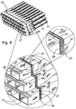
- shows a variation of the embodiment shown in
Figure 7a , in which there is a seal. -
Figure 1 shows one example of theheadbox 10 of a fiber web machine at a rough schematic level, as a cross-section seen from the side. The fiber suspension is led, in a manner that is, as such known, from the headbox's 10inlet header 11 through amanifold tube bank 12 to aturbulence generator 14, which is formed ofseveral flow pipes 17 set in a row formation and overlapping each other. From theturbulence generator 14, the fiber suspension proceeds to aslice channel 35 and from there onwards past a schematically-shownslice lip 34 to the forming wire (not shown). In addition, in the discharge opening 35 there can be sheets (not shown) following theturbulence generator 14. In theturbulence generator 14, the consistency profile of the fiber suspension evens out and any floccules that may have formed in the fiber suspension are dispersed. The floccules are dispersed by causing shear forces and turbulence in the flow. The turbulence is sufficient to keep the fibers separate and to disperse the floccules, without, however, disturbing the forming of the web on the wire. -
Figure 2 shows an axial view of one example of aflow pipe 17, which is thus intended for theturbulence generator 14 of aheadbox 10. Theflow pipe 17 has two ends in the flow direction, i.e. aninlet end 13 and anoutlet end 15. Aflow channel 16, through which the flow led into the pipe from theinlet end 13 travels to theoutlet end 15 and out of theflow pipe 17, is formed between theends flow channel 16 includes two consecutive flow sections, the inlet-end flow section 18 and the outlet-end flow section 19. The mutual flow cross-sectional surface-areas of theflow sections step 20 between them. Thestep 20 now forms its own area between thesections end flow section 18 can be, for example, circular while the internal cross-section of the outlet-end flow section 19 can be, for example, square. Correspondingly, the external cross-section of the inlet-end flow section 18 is also circular while the external cross-section of the outlet-end flow section 19 is also square, more generally angular. The external cross-section of the outlet-end flow section 19 can also be a pentagon or a hexagon. In any event, its sides 21.1 - 21.4 have a planar external surface. - The
flow pipe 17 can be manufactured in several different ways. One way is to manufacture it using a casting process. Theflow pipe 17 can then be of a material that is, for example, a plastic. Polyethylene, or thermoplastic in general, can be given as an example of plastics. Athermoplastic flow pipe 17 can also be welded, if the operation in question is seen to be necessary, for example when assembling aturbulence generator 14 frompipes 17. A plastic flow pipe will resist water, chemicals, and washing agents. Various machining methods can also be used to manufacture a flow pipe from, for example, metals or composites. Yet another example of a possible manufacturing method is 3D printing, which also permits the economical manufacture of small batches. One significant advantage of moulding is that theflow pipe 17 is then manufactured mainly as a single-phase process. In addition, another advantage of the moulding process is the high degree of integration of the secondary operations relating to the operating environment of the flow pipe. The shaping of theflow chamber 16 of theflow pipe 17 can also be freely selected, within the limits of, for example, the injection-moulding technique. - At least one
groove 24 and at least oneprotrusion 25 are arranged in the external surface 21.1 - 21.4 of the outlet-end flow section 19 of theflow pipe 17. In theflow section 19, thegroove 24 and theprotrusion 25 are on its opposite external surfaces 21.3, 21.1; 21.2, 21.4. With the aid of theirformations flow pipe 17 can be attached to theadjacent flow pipes 17' surrounding it, and particularly to their corresponding attachment formations 24', 25' (for example,Figures 4a - 4d ), when theturbulence generator 14 is, for example, assembled and installed in aheadbox 10.Figures 3 shows a bank of pipes assembled fromflow pipes Figure 2 , which can form at least part of aturbulence generator 14. Theadjacent flow pipe 17' can be located above or below, or to the right or left, relative to theflow pipe 17. - As already stated above, the
groove 24 and theprotrusion 25 can be located in theflow pipe 17 on the opposing external surfaces 21.1 - 21.4 of its outlet-end flow section 19. Thus, each external side surface of theflow section 19 has at least one connection formation, which is at least onegroove 24, or at least oneprotrusion 25. Correspondingly, there is at least oneprotrusion 25 on the opposing external side surface of theflow section 19, relative to the external side surface with thegroove 24 in question, or at least onegroove 24, which permits theflow pipes flow pipe 17 is, at least in the outlet-end section 19, planar, in which case a tight connection is created between theflow pipe 17 and theadjacent flow pipe 17' of theturbulence generator 14, thus, for its part, permitting theflow pipes - In the embodiment of
Figure 2 , thegroove 24 is on the righthand side external surface 21.2 of theflow section 19 and, in addition, also on its lower external surface 21.3, if theflow pipe 17 is examined from theoutlet end 15. Correspondingly, theprotrusion 25 is on the upper external surface 21.11 and left-hand side external surface 21.4 of theflow section 19. In this way, theflow pipe 17 can be attached on all sides to theadjacent flow pipe 17'. Of course, if theflow pipe 17 will meet one of the edges of theturbulence generator 14, it will then be possible to manage with even only a single groove-protrusion pair on each pipe. - In the bank of pipes according to
Figure 3 , theflow pipes 17 are in stacked in rows. The adjacent pipes in the same row are attached to each other by groove-protrusion joints fitted to each other in the side surfaces 21.2, 21.4 of the outlet-end flow section 19. Correspondingly, the rows of pipes on top of each other in the vertical direction are attached to each other by groove-protrusion joints in the upper and lower surfaces 21.1, 21.3 of the outlet-end of theflow section 19. The totality is a tight pipe package, in which thepipes -
Figures 4a - 4d show some examples of ways to attach theflow pipes grooves 24, 24' andprotrusions 25, 25' arranged in thepipes grooves 24 andprotrusions 25 of theflow pipe 17 can be arranged to form a form-locking joint with the corresponding joint forms 24', 25' in theadjacent flow pipes 17'. As can be seen fromFigures 4a - 4d , the shape-locking joint can be created in several different ways. - In
Figure 4a , the shape-closure joint is formed by agroove 24 and aprotrusion 25, which are rounded in shape. InFigure 4b , the shape-closure joint is formed by agroove 24 and aprotrusion 25, which are angular. InFigure 4c , the shape-closure joint is formed by twogrooves 24 and twoprotrusions 25 fitted to the same external side of the pipe, which are now also angular in shape. InFigures 4a - 4c , the shape-closure joint is based on the interference fit between thegroove 24 and theprotrusion 25. The dimensions of the groove and the protrusion are then adapted relative to each other, in such a way that, when they are pressed against each other, thegroove 24 compresses theprotrusion 25. Generally, inFigures 4a - 4c , at least twogrooves 24 and at least twoprotrusions 25 are arranged on the external surface 21.1 - 21.4 of the outlet-end of theflow section 19 of theflow pipe 17. Thegrooves 24 andprotrusions 25 are on opposite external surfaces 21.1 - 21.4 of the outlet-end of theflow section 19. - In
Figure 4d , the shape-closure joint is a dovetail joint. Now, on the two external surfaces 21.3, 21.1, which are opposite to each other, of the outlet-end flow section 19 of theflow pipe 17, there is arranged agroove 24 on one surface 21.3 and aprotrusion 25 on the other surface 21.1. Thegroove 24 and theprotrusion 25 are arranged to form a dovetail joint with the corresponding joint formations 24', 25' of theadjacent flow pipes 17'. In each embodiment, as well as the locking, thegroove 24 and theprotrusion 25 also form a labyrinth seal for theturbulence generator 14 formed by theflow pipes headbox 10. Yet other possible joint shapes are, for example, spherical, hemispherical, and angular. Generally, it is possible to refer to the connection of the flow pipes to the rest of the construction of the turbulence generator by means of shape-closure joints according to the "plug-and-play" principle. -
Figures 5a - 5d show an axial view of the turbulence generator banks formed from theflow pipes Figures 4a - 4d . Irrespective of the type of attachment of thepipes Figures 5a - 5c , theprotrusions 25 are on upper surface of the pipes and thegrooves 24 on the lower surface of thepipes 24. InFigure 5d , the situation is the opposite, i.e. the protrusions are on the lower surface and the grooves on the upper surface. The flow pipe can be rotated, which further increases its versatility. -
Figures 4a - 4d also show that the stacked flow pipe rows can, connected to each other, form a location for aflow sheet 28. It can be seen more clearly fromFigure 2 that, for this purpose, there can be at least one shaping 26 at the outlet end 15 of theflow pipe 17, which is arranged to form, together with an upper orlower flow pipe 17', anattachment 31 for aflow sheet 28. At the outlet end 15 of theflow pipe 17, there is alip 26, at the front edge of which there is a protrusion. -
Figure 6 shows an arrangement, in which thesheets 28 are installed at the end of the bank of pipes. Theattachment rods 30 at the inlet-end edge of thesheet 28 are inslots 31 formed by the stackedflow pipes slots 31 can then be, for example, 6 - 15 mm. In particular inpipes sheets 28 is achieved in the ends of thepipes - In addition,
Figure 6 shows that the joints of the stackedflow pipes slot 31 reserved for the lamella. This, for its part, also helps theturbulence generator 14 to remain clean. - It can also be seen from the insert of
Figure 6 , that the turbulence generator's tightness and the cleanliness of its trailing edge can, if necessary, be ensured by reflow welding the seams of the outlet end. The welded joint 32 in question can be made simple by melting the seams, in which case additional material will not be required to close the seam. The intention of the welded joint is to remove the joint grooves and thus ensure, for example, the tightness and uniformity of the joint location. In other words, the welded joint nevertheless permits thepipes 17 to be also be easily removed later with little effort, for example, in order to change them. -
Figures 7a and 7b show one significant benefit that is made possible by theflow pipe 17. The shape-closure connection of aflow pipe 17 to anadjacent flow pipe 17' permits the location of theflow pipe 17 to be altered steplessly horizontally and vertically. This gives a degree of freedom for altering the flow of theturbulence generator 14. The shape-closure joint between theflow pipes headbox 10, the groove-protrusion joints of the flow pipes do not limit the movement of the flow pipes, instead the flow pipe rows can move relative to each other. In particular, if the flow pipes are manufactured, for example, from plastic, a force exceeding the static friction will be able to slide the rows of flow pipes relative to the pipe/groove. Plastic flexes and slides, but on the other hand, its static friction also ensures that the pipes will remain securely in place. In addition, pipes made from plastic withstand small static forces. Yet another significant difference of aflow pipe 17 made from plastic is that, for example, the local thermal expansion of small-tolerance flow pipes turbulence generator 14. -
Figure 9 shows yet another embodiment of the invention, which is a modification of that shown inFigure 7a . In it, an O-ring seal 29 is added to theprotrusion 25 andgroove 24 arranged in the external surface of theflow pipes grooves 27 for the O-ring seal 29 in theprotrusions 25 andgrooves 24. There can advantageously be two O-ring grooves 27 in the external surface of theflow pipes rings 29 can be in adifferent groove 27 in every second pipe and the O-ring can thus go into the correspondinggroove 27 in the adjacent pipe. Alternatively, there can be O-rings 29 in bothgrooves 27 in every second pipe, and none at all in the adjacent pipe. By means of this solution, the corner location of thepipes 17 too are sealed. -
Figures 8a - 8c show examples of theturbulence generator 14 of a fiber web machine, examined from different directions. Theturbulence generator 14 includesseveral flow pipes 17. At least one groove and at least one protrusion, by which theflow pipe 17 is attached to theadjacent pipe 17, is arranged in the external surface of the outlet ends of theflow pipes 17. Thepipes 17 are attached to oneend 31 of abox structure 33 formed from plate-like elements. There are holes in theend plate 31, into which thepipes 17 fit tightly at the inlet end. Correspondingly, at the other end the pipe package can expand. Due to lateral thermal expansion, the pipes seal theplate 31 at the outlet end. At the outlet end 19 of thepipes 17, the flow pipes at the edges of theturbulence generator 14 can be tightened, for example, by means of a tensioned band (not shown) around the pipe package. If thebox structure 33 extends right to the outlet end 15 of the pipes, there can be a metal plate at the upper and lower edge of the outlet end 31 of thebox 33, in which there is a claw fitted to the locking shapes in the external sides of the pipes at the edges and thick plate pieces of the actual box structure, on top of the locking metal plate. - The
turbulence generator 14 of the headbox according to the invention can be, for example, nine metres wide and have three rows. In that case, in one row there will be one hundred flow pipes over a distance of three meters and thus there will be more than one thousand flow pipes in the headbox in question. According to the invention, by means of the flow pipe, significant savings will be obtained in both labour and material costs and especially when assembling the headbox. At the same time, the mass of theturbulence generator 14 will be less than usual, particularly if the pipes are plastic. The flow pipes will also be of even quality and the level of turbulence will be uniform over the entire width of the slice opening. - It must be understood that the above description and the related figures are only intended to illustrate the present invention, i.e. the invention is thus in no way restricted to only the embodiments disclosed, but many different variations and adaptations of the invention, which fall within the scope of the invention as defined in the accompanying claims , are possible.
Claims (7)
- Turbulence generator (14) of a headbox (10) of a fiber web machine, which includes a plurality of flow pipes (17, 17') wherein each flow pipe has two ends, an inlet end (13) and an outlet end (15), and between which ends (13, 15) there is a flow channel (16), wherein at least one groove (24) and at least one protrusion (25) is arranged in the external surface (21.1 - 21.4) of each flow pipe (17, 17') in order to attach each flow pipe (17, 17') to adjacent flow pipes (17, 17') of the plurality of flow pipes (17, 17'),
characterized in that
the at least one groove (24) and the at least one protrusion (25) of the flow pipe (17, 17') are formed in perpendicular direction to the axis of the flow pipe (17, 17') such that adjacent grooves (24) and protrusions (25) of the flow pipes (17, 17') are joined to each other to connect the adjacent flow pipes (17, 17') to each other by means of counter-pair joint formations (24, 25, 24', 25'). - Turbulence generator (14) according to claim 1, wherein the flow channel (16) has at least two flow sections, an inlet-end flow section (18) and an outlet-end flow section (19), wherein the outlet-end flow section (19) has an angular external cross- section and the at least one groove (24) and at least one protrusion (25) are arranged in the external surface (21.1 - 21.4) of the outlet-end flow section (19).
- Turbulence generator (14) according to claim 2, characterized in that the at least one groove (24) and at least one protrusion (25) are arranged on opposite sides of the external surface (21.1 - 21.4) of the outlet-end flow section (19).
- Turbulence generator (14) according to any of claims 1 - 3, characterized in that the groove (24) and protrusion (25) of the flow pipe (17, 17') are arranged to form a shape-locking connection to the corresponding counter-pair joint formation (24', 25') of the adjacent flow pipes (17, 17').
- Turbulence generator (14) according to any of claims 1 - 4, characterized in that the groove (24) and protrusion (25) are arranged to form a labyrinth seal to the turbulence generator structure (14) formed by the flow pipes (17, 17').
- Turbulence generator (14) according to any of claims 1 - 5, characterized in that on the two external surfaces (21.3, 21.1), which are opposite to each other, of the outlet end of the flow section (19) of the flow pipe (17, 17'), there is arranged a groove (24) on one surface (21.3) and a protrusion (25) on the other surface (21.1) and the groove (24) and protrusion (25) are arranged to form a dovetail joint with the corresponding counter-pair joint formations (24', 25') of the adjacent flow pipes (17, 17').
- Turbulence generator (14) according to any of claims 1 - 6, characterized in that a shaping (26), which is arranged to form an attachment (31) for a flow sheet (28) with the flow pipes (17, 17') below and/or above, is arranged in the outlet end (15) of the flow pipe (17, 17').
Applications Claiming Priority (2)
| Application Number | Priority Date | Filing Date | Title |
|---|---|---|---|
| FI20106358A FI122895B (en) | 2010-12-21 | 2010-12-21 | FLOW PIPE FOR A TURBULEN GENERATOR IN A FIBER BANAMASKIN AND TURBULEN GENERATOR FOR A FIBER BANAMASKIN |
| PCT/FI2011/051133 WO2012085343A1 (en) | 2010-12-21 | 2011-12-19 | Flow pipe for the turbulence generator of the headbox of a fibre web machine and a turbulence generator of the headbox of a fibre web machine |
Publications (3)
| Publication Number | Publication Date |
|---|---|
| EP2655734A1 EP2655734A1 (en) | 2013-10-30 |
| EP2655734A4 EP2655734A4 (en) | 2014-07-09 |
| EP2655734B1 true EP2655734B1 (en) | 2016-09-28 |
Family
ID=43415047
Family Applications (1)
| Application Number | Title | Priority Date | Filing Date |
|---|---|---|---|
| EP11851085.8A Not-in-force EP2655734B1 (en) | 2010-12-21 | 2011-12-19 | Turbulence generator of a headbox of a fibre web machine |
Country Status (4)
| Country | Link |
|---|---|
| EP (1) | EP2655734B1 (en) |
| CN (1) | CN103261515B (en) |
| FI (1) | FI122895B (en) |
| WO (1) | WO2012085343A1 (en) |
Families Citing this family (6)
| Publication number | Priority date | Publication date | Assignee | Title |
|---|---|---|---|---|
| CN104343037A (en) * | 2014-11-17 | 2015-02-11 | 张珣 | Active pulp shooting machine |
| DE102016114040A1 (en) * | 2016-07-29 | 2018-02-01 | Voith Patent Gmbh | Flow module and method for producing a flow module for a headbox of a paper machine |
| DE102017122538A1 (en) * | 2017-09-28 | 2019-03-28 | Voith Patent Gmbh | Method and device for producing a flow element |
| DE102018120820A1 (en) * | 2018-08-27 | 2020-02-27 | Voith Patent Gmbh | turbulence generator |
| CN109706775B (en) * | 2019-03-15 | 2020-12-01 | 河南江河纸业股份有限公司 | Turbulence generator round-to-square gradual change pipe and preparation method and equipment thereof |
| DE102023130045A1 (en) * | 2023-10-31 | 2025-04-30 | Voith Patent Gmbh | Lamella fastening device for a headbox of a machine for producing a fibrous web |
Family Cites Families (7)
| Publication number | Priority date | Publication date | Assignee | Title |
|---|---|---|---|---|
| FI66931C (en) | 1983-01-04 | 1984-12-10 | Tampella Oy Ab | HAOLSKIVA FOER EN INLOPPSLAODA FOER EN PAPPERSMASKIN |
| US5183537A (en) * | 1991-10-07 | 1993-02-02 | Beloit Technologies, Inc. | Headbox tube bank apparatus and method of directing flow therethrough |
| DE19830872A1 (en) * | 1998-07-10 | 2000-01-13 | Voith Sulzer Papiertech Patent | Stock inlet turbulence generator for a papermaking machine |
| WO2001021886A1 (en) | 1999-09-22 | 2001-03-29 | Metso Paper, Inc. | Turbulence pipe with at least one corrugated wall and a procedure for forming it |
| EP2129830A4 (en) * | 2007-03-01 | 2012-06-13 | Metso Paper Karlstad Ab | Structural element for a functional member of a headbox in a web-manufacturing machine, functional member and headbox made thereof, and associated methods |
| US7955474B2 (en) * | 2007-12-11 | 2011-06-07 | Paperchine Inc. | Tube bank apparatus for distributing stock |
| DE102008042032A1 (en) * | 2008-09-12 | 2010-03-18 | Voith Patent Gmbh | Turbulence generator for use in regulator of machine for producing e.g. paper web, has turbulence pipes arranged in gaps and lines for guiding and distribution of material suspension along flow direction and connected with connecting part |
-
2010
- 2010-12-21 FI FI20106358A patent/FI122895B/en not_active IP Right Cessation
-
2011
- 2011-12-19 WO PCT/FI2011/051133 patent/WO2012085343A1/en not_active Ceased
- 2011-12-19 CN CN201180059858.XA patent/CN103261515B/en not_active Expired - Fee Related
- 2011-12-19 EP EP11851085.8A patent/EP2655734B1/en not_active Not-in-force
Also Published As
| Publication number | Publication date |
|---|---|
| EP2655734A4 (en) | 2014-07-09 |
| FI20106358A0 (en) | 2010-12-21 |
| FI122895B (en) | 2012-08-31 |
| CN103261515A (en) | 2013-08-21 |
| EP2655734A1 (en) | 2013-10-30 |
| WO2012085343A1 (en) | 2012-06-28 |
| CN103261515B (en) | 2015-04-01 |
| FI20106358L (en) | 2012-06-22 |
Similar Documents
| Publication | Publication Date | Title |
|---|---|---|
| WO2012085343A1 (en) | Flow pipe for the turbulence generator of the headbox of a fibre web machine and a turbulence generator of the headbox of a fibre web machine | |
| KR101672573B1 (en) | Plate type heat exchanger and method of manufacturing heat exchanger plate | |
| US4639165A (en) | Drainage tube | |
| CN101460803B (en) | Heat exchanger plate and plate heat exchanger | |
| RU2555087C1 (en) | Fixing of sealing gasket in plate heat exchanger | |
| EP1386999B1 (en) | Tube bank structure, and flow tube producing method | |
| JPS61262593A (en) | Heat exchanger | |
| US20120168105A1 (en) | Headbox for a machine for producing a fibrous web | |
| KR101865376B1 (en) | Manufacturing method of a column with integrated diaphragm | |
| KR102056259B1 (en) | Rectangular cft columns with internal diaphragm and concrete lnduction tubes | |
| IT8323457A1 (en) | A process for producing a tubular distribution arrangement, as well as a heat exchanger collector vessel, produced according to said process | |
| EP1371793B1 (en) | Grid for a suspended ceiling | |
| FI78938B (en) | INLOPPSLAODA FOER PAPPERSMASKIN. | |
| CN107558637B (en) | Cast-in-place wall grouting structure, cast-in-place wall and construction method thereof | |
| US12292245B2 (en) | Impingement device for heat exchanger inlet tube protection | |
| CN112746702B (en) | A floor structure composed of assembly boxes | |
| KR102158021B1 (en) | Joint structure between the steel column with square cross section and the composite girder | |
| KR200313209Y1 (en) | Inner wall assembly in filtration plant for waterworks | |
| US6352616B1 (en) | Jointless lamellae for a headbox | |
| FI69330C (en) | TURBULENSGENERATOR I INLOPPSLAODA FOER PAPPERSMASKIN OCH FOERFARANDE FOER TILLVERKNING AV DENNA | |
| EP3239396B1 (en) | A support frame structure for a fiber web machine and a fiber web machine | |
| KR20040073725A (en) | Inner wall assembly in filtration plant for waterworks | |
| CN218911351U (en) | Novel PP welded geogrid | |
| EP3938593B1 (en) | Method for constructing a closed steel sheet structure and closed steel sheet structure | |
| CN215857595U (en) | Eight-leg medium-sized C-type jacket suitable for standardized design of Bohai sea pelley region |
Legal Events
| Date | Code | Title | Description |
|---|---|---|---|
| PUAI | Public reference made under article 153(3) epc to a published international application that has entered the european phase |
Free format text: ORIGINAL CODE: 0009012 |
|
| 17P | Request for examination filed |
Effective date: 20130503 |
|
| AK | Designated contracting states |
Kind code of ref document: A1 Designated state(s): AL AT BE BG CH CY CZ DE DK EE ES FI FR GB GR HR HU IE IS IT LI LT LU LV MC MK MT NL NO PL PT RO RS SE SI SK SM TR |
|
| DAX | Request for extension of the european patent (deleted) | ||
| RAP1 | Party data changed (applicant data changed or rights of an application transferred) |
Owner name: VALMET TECHNOLOGIES, INC. |
|
| A4 | Supplementary search report drawn up and despatched |
Effective date: 20140612 |
|
| RIC1 | Information provided on ipc code assigned before grant |
Ipc: D21F 1/02 20060101AFI20140605BHEP |
|
| GRAP | Despatch of communication of intention to grant a patent |
Free format text: ORIGINAL CODE: EPIDOSNIGR1 |
|
| INTG | Intention to grant announced |
Effective date: 20160413 |
|
| GRAS | Grant fee paid |
Free format text: ORIGINAL CODE: EPIDOSNIGR3 |
|
| GRAA | (expected) grant |
Free format text: ORIGINAL CODE: 0009210 |
|
| AK | Designated contracting states |
Kind code of ref document: B1 Designated state(s): AL AT BE BG CH CY CZ DE DK EE ES FI FR GB GR HR HU IE IS IT LI LT LU LV MC MK MT NL NO PL PT RO RS SE SI SK SM TR |
|
| REG | Reference to a national code |
Ref country code: GB Ref legal event code: FG4D |
|
| REG | Reference to a national code |
Ref country code: CH Ref legal event code: EP |
|
| REG | Reference to a national code |
Ref country code: AT Ref legal event code: REF Ref document number: 832872 Country of ref document: AT Kind code of ref document: T Effective date: 20161015 |
|
| REG | Reference to a national code |
Ref country code: IE Ref legal event code: FG4D |
|
| REG | Reference to a national code |
Ref country code: DE Ref legal event code: R096 Ref document number: 602011030850 Country of ref document: DE |
|
| REG | Reference to a national code |
Ref country code: LT Ref legal event code: MG4D |
|
| PG25 | Lapsed in a contracting state [announced via postgrant information from national office to epo] |
Ref country code: LT Free format text: LAPSE BECAUSE OF FAILURE TO SUBMIT A TRANSLATION OF THE DESCRIPTION OR TO PAY THE FEE WITHIN THE PRESCRIBED TIME-LIMIT Effective date: 20160928 Ref country code: RS Free format text: LAPSE BECAUSE OF FAILURE TO SUBMIT A TRANSLATION OF THE DESCRIPTION OR TO PAY THE FEE WITHIN THE PRESCRIBED TIME-LIMIT Effective date: 20160928 Ref country code: FI Free format text: LAPSE BECAUSE OF FAILURE TO SUBMIT A TRANSLATION OF THE DESCRIPTION OR TO PAY THE FEE WITHIN THE PRESCRIBED TIME-LIMIT Effective date: 20160928 Ref country code: NO Free format text: LAPSE BECAUSE OF FAILURE TO SUBMIT A TRANSLATION OF THE DESCRIPTION OR TO PAY THE FEE WITHIN THE PRESCRIBED TIME-LIMIT Effective date: 20161228 Ref country code: HR Free format text: LAPSE BECAUSE OF FAILURE TO SUBMIT A TRANSLATION OF THE DESCRIPTION OR TO PAY THE FEE WITHIN THE PRESCRIBED TIME-LIMIT Effective date: 20160928 |
|
| REG | Reference to a national code |
Ref country code: NL Ref legal event code: MP Effective date: 20160928 |
|
| PG25 | Lapsed in a contracting state [announced via postgrant information from national office to epo] |
Ref country code: NL Free format text: LAPSE BECAUSE OF FAILURE TO SUBMIT A TRANSLATION OF THE DESCRIPTION OR TO PAY THE FEE WITHIN THE PRESCRIBED TIME-LIMIT Effective date: 20160928 Ref country code: LV Free format text: LAPSE BECAUSE OF FAILURE TO SUBMIT A TRANSLATION OF THE DESCRIPTION OR TO PAY THE FEE WITHIN THE PRESCRIBED TIME-LIMIT Effective date: 20160928 Ref country code: GR Free format text: LAPSE BECAUSE OF FAILURE TO SUBMIT A TRANSLATION OF THE DESCRIPTION OR TO PAY THE FEE WITHIN THE PRESCRIBED TIME-LIMIT Effective date: 20161229 Ref country code: SE Free format text: LAPSE BECAUSE OF FAILURE TO SUBMIT A TRANSLATION OF THE DESCRIPTION OR TO PAY THE FEE WITHIN THE PRESCRIBED TIME-LIMIT Effective date: 20160928 |
|
| PG25 | Lapsed in a contracting state [announced via postgrant information from national office to epo] |
Ref country code: RO Free format text: LAPSE BECAUSE OF FAILURE TO SUBMIT A TRANSLATION OF THE DESCRIPTION OR TO PAY THE FEE WITHIN THE PRESCRIBED TIME-LIMIT Effective date: 20160928 Ref country code: EE Free format text: LAPSE BECAUSE OF FAILURE TO SUBMIT A TRANSLATION OF THE DESCRIPTION OR TO PAY THE FEE WITHIN THE PRESCRIBED TIME-LIMIT Effective date: 20160928 |
|
| PG25 | Lapsed in a contracting state [announced via postgrant information from national office to epo] |
Ref country code: IS Free format text: LAPSE BECAUSE OF FAILURE TO SUBMIT A TRANSLATION OF THE DESCRIPTION OR TO PAY THE FEE WITHIN THE PRESCRIBED TIME-LIMIT Effective date: 20170128 Ref country code: ES Free format text: LAPSE BECAUSE OF FAILURE TO SUBMIT A TRANSLATION OF THE DESCRIPTION OR TO PAY THE FEE WITHIN THE PRESCRIBED TIME-LIMIT Effective date: 20160928 Ref country code: SM Free format text: LAPSE BECAUSE OF FAILURE TO SUBMIT A TRANSLATION OF THE DESCRIPTION OR TO PAY THE FEE WITHIN THE PRESCRIBED TIME-LIMIT Effective date: 20160928 Ref country code: PL Free format text: LAPSE BECAUSE OF FAILURE TO SUBMIT A TRANSLATION OF THE DESCRIPTION OR TO PAY THE FEE WITHIN THE PRESCRIBED TIME-LIMIT Effective date: 20160928 Ref country code: PT Free format text: LAPSE BECAUSE OF FAILURE TO SUBMIT A TRANSLATION OF THE DESCRIPTION OR TO PAY THE FEE WITHIN THE PRESCRIBED TIME-LIMIT Effective date: 20170130 Ref country code: SK Free format text: LAPSE BECAUSE OF FAILURE TO SUBMIT A TRANSLATION OF THE DESCRIPTION OR TO PAY THE FEE WITHIN THE PRESCRIBED TIME-LIMIT Effective date: 20160928 Ref country code: BE Free format text: LAPSE BECAUSE OF FAILURE TO SUBMIT A TRANSLATION OF THE DESCRIPTION OR TO PAY THE FEE WITHIN THE PRESCRIBED TIME-LIMIT Effective date: 20160928 Ref country code: CZ Free format text: LAPSE BECAUSE OF FAILURE TO SUBMIT A TRANSLATION OF THE DESCRIPTION OR TO PAY THE FEE WITHIN THE PRESCRIBED TIME-LIMIT Effective date: 20160928 Ref country code: BG Free format text: LAPSE BECAUSE OF FAILURE TO SUBMIT A TRANSLATION OF THE DESCRIPTION OR TO PAY THE FEE WITHIN THE PRESCRIBED TIME-LIMIT Effective date: 20161228 |
|
| REG | Reference to a national code |
Ref country code: DE Ref legal event code: R097 Ref document number: 602011030850 Country of ref document: DE |
|
| PG25 | Lapsed in a contracting state [announced via postgrant information from national office to epo] |
Ref country code: IT Free format text: LAPSE BECAUSE OF FAILURE TO SUBMIT A TRANSLATION OF THE DESCRIPTION OR TO PAY THE FEE WITHIN THE PRESCRIBED TIME-LIMIT Effective date: 20160928 |
|
| PG25 | Lapsed in a contracting state [announced via postgrant information from national office to epo] |
Ref country code: DK Free format text: LAPSE BECAUSE OF FAILURE TO SUBMIT A TRANSLATION OF THE DESCRIPTION OR TO PAY THE FEE WITHIN THE PRESCRIBED TIME-LIMIT Effective date: 20160928 |
|
| REG | Reference to a national code |
Ref country code: CH Ref legal event code: PL |
|
| PLBE | No opposition filed within time limit |
Free format text: ORIGINAL CODE: 0009261 |
|
| STAA | Information on the status of an ep patent application or granted ep patent |
Free format text: STATUS: NO OPPOSITION FILED WITHIN TIME LIMIT |
|
| GBPC | Gb: european patent ceased through non-payment of renewal fee |
Effective date: 20161228 |
|
| 26N | No opposition filed |
Effective date: 20170629 |
|
| PG25 | Lapsed in a contracting state [announced via postgrant information from national office to epo] |
Ref country code: MC Free format text: LAPSE BECAUSE OF FAILURE TO SUBMIT A TRANSLATION OF THE DESCRIPTION OR TO PAY THE FEE WITHIN THE PRESCRIBED TIME-LIMIT Effective date: 20160928 |
|
| REG | Reference to a national code |
Ref country code: FR Ref legal event code: ST Effective date: 20170831 |
|
| REG | Reference to a national code |
Ref country code: IE Ref legal event code: MM4A |
|
| PG25 | Lapsed in a contracting state [announced via postgrant information from national office to epo] |
Ref country code: FR Free format text: LAPSE BECAUSE OF NON-PAYMENT OF DUE FEES Effective date: 20170102 Ref country code: CH Free format text: LAPSE BECAUSE OF NON-PAYMENT OF DUE FEES Effective date: 20161231 Ref country code: LU Free format text: LAPSE BECAUSE OF NON-PAYMENT OF DUE FEES Effective date: 20161219 Ref country code: LI Free format text: LAPSE BECAUSE OF NON-PAYMENT OF DUE FEES Effective date: 20161231 |
|
| PG25 | Lapsed in a contracting state [announced via postgrant information from national office to epo] |
Ref country code: IE Free format text: LAPSE BECAUSE OF NON-PAYMENT OF DUE FEES Effective date: 20161219 Ref country code: SI Free format text: LAPSE BECAUSE OF FAILURE TO SUBMIT A TRANSLATION OF THE DESCRIPTION OR TO PAY THE FEE WITHIN THE PRESCRIBED TIME-LIMIT Effective date: 20160928 Ref country code: GB Free format text: LAPSE BECAUSE OF NON-PAYMENT OF DUE FEES Effective date: 20161228 |
|
| PGFP | Annual fee paid to national office [announced via postgrant information from national office to epo] |
Ref country code: DE Payment date: 20171211 Year of fee payment: 7 |
|
| PGFP | Annual fee paid to national office [announced via postgrant information from national office to epo] |
Ref country code: AT Payment date: 20171221 Year of fee payment: 7 |
|
| PG25 | Lapsed in a contracting state [announced via postgrant information from national office to epo] |
Ref country code: HU Free format text: LAPSE BECAUSE OF FAILURE TO SUBMIT A TRANSLATION OF THE DESCRIPTION OR TO PAY THE FEE WITHIN THE PRESCRIBED TIME-LIMIT; INVALID AB INITIO Effective date: 20111219 Ref country code: CY Free format text: LAPSE BECAUSE OF FAILURE TO SUBMIT A TRANSLATION OF THE DESCRIPTION OR TO PAY THE FEE WITHIN THE PRESCRIBED TIME-LIMIT Effective date: 20160928 |
|
| PG25 | Lapsed in a contracting state [announced via postgrant information from national office to epo] |
Ref country code: MK Free format text: LAPSE BECAUSE OF FAILURE TO SUBMIT A TRANSLATION OF THE DESCRIPTION OR TO PAY THE FEE WITHIN THE PRESCRIBED TIME-LIMIT Effective date: 20160928 |
|
| PG25 | Lapsed in a contracting state [announced via postgrant information from national office to epo] |
Ref country code: MT Free format text: LAPSE BECAUSE OF NON-PAYMENT OF DUE FEES Effective date: 20161219 |
|
| PG25 | Lapsed in a contracting state [announced via postgrant information from national office to epo] |
Ref country code: AL Free format text: LAPSE BECAUSE OF FAILURE TO SUBMIT A TRANSLATION OF THE DESCRIPTION OR TO PAY THE FEE WITHIN THE PRESCRIBED TIME-LIMIT Effective date: 20160928 Ref country code: TR Free format text: LAPSE BECAUSE OF FAILURE TO SUBMIT A TRANSLATION OF THE DESCRIPTION OR TO PAY THE FEE WITHIN THE PRESCRIBED TIME-LIMIT Effective date: 20160928 |
|
| REG | Reference to a national code |
Ref country code: DE Ref legal event code: R119 Ref document number: 602011030850 Country of ref document: DE |
|
| REG | Reference to a national code |
Ref country code: AT Ref legal event code: MM01 Ref document number: 832872 Country of ref document: AT Kind code of ref document: T Effective date: 20181219 |
|
| PG25 | Lapsed in a contracting state [announced via postgrant information from national office to epo] |
Ref country code: DE Free format text: LAPSE BECAUSE OF NON-PAYMENT OF DUE FEES Effective date: 20190702 |
|
| REG | Reference to a national code |
Ref country code: AT Ref legal event code: UEP Ref document number: 832872 Country of ref document: AT Kind code of ref document: T Effective date: 20160928 |
|
| PG25 | Lapsed in a contracting state [announced via postgrant information from national office to epo] |
Ref country code: AT Free format text: LAPSE BECAUSE OF NON-PAYMENT OF DUE FEES Effective date: 20181219 |