EP2655165B2 - Ski slope groomer and relative control method - Google Patents
Ski slope groomer and relative control method Download PDFInfo
- Publication number
- EP2655165B2 EP2655165B2 EP11820805.7A EP11820805A EP2655165B2 EP 2655165 B2 EP2655165 B2 EP 2655165B2 EP 11820805 A EP11820805 A EP 11820805A EP 2655165 B2 EP2655165 B2 EP 2655165B2
- Authority
- EP
- European Patent Office
- Prior art keywords
- power transmission
- electric
- transmission assembly
- groomer
- mechanical power
- Prior art date
- Legal status (The legal status is an assumption and is not a legal conclusion. Google has not performed a legal analysis and makes no representation as to the accuracy of the status listed.)
- Active
Links
Images
Classifications
-
- B—PERFORMING OPERATIONS; TRANSPORTING
- B60—VEHICLES IN GENERAL
- B60K—ARRANGEMENT OR MOUNTING OF PROPULSION UNITS OR OF TRANSMISSIONS IN VEHICLES; ARRANGEMENT OR MOUNTING OF PLURAL DIVERSE PRIME-MOVERS IN VEHICLES; AUXILIARY DRIVES FOR VEHICLES; INSTRUMENTATION OR DASHBOARDS FOR VEHICLES; ARRANGEMENTS IN CONNECTION WITH COOLING, AIR INTAKE, GAS EXHAUST OR FUEL SUPPLY OF PROPULSION UNITS IN VEHICLES
- B60K6/00—Arrangement or mounting of plural diverse prime-movers for mutual or common propulsion, e.g. hybrid propulsion systems comprising electric motors and internal combustion engines
- B60K6/20—Arrangement or mounting of plural diverse prime-movers for mutual or common propulsion, e.g. hybrid propulsion systems comprising electric motors and internal combustion engines the prime-movers consisting of electric motors and internal combustion engines, e.g. HEVs
- B60K6/22—Arrangement or mounting of plural diverse prime-movers for mutual or common propulsion, e.g. hybrid propulsion systems comprising electric motors and internal combustion engines the prime-movers consisting of electric motors and internal combustion engines, e.g. HEVs characterised by apparatus, components or means specially adapted for HEVs
- B60K6/36—Arrangement or mounting of plural diverse prime-movers for mutual or common propulsion, e.g. hybrid propulsion systems comprising electric motors and internal combustion engines the prime-movers consisting of electric motors and internal combustion engines, e.g. HEVs characterised by apparatus, components or means specially adapted for HEVs characterised by the transmission gearings
- B60K6/365—Arrangement or mounting of plural diverse prime-movers for mutual or common propulsion, e.g. hybrid propulsion systems comprising electric motors and internal combustion engines the prime-movers consisting of electric motors and internal combustion engines, e.g. HEVs characterised by apparatus, components or means specially adapted for HEVs characterised by the transmission gearings with the gears having orbital motion
-
- B—PERFORMING OPERATIONS; TRANSPORTING
- B60—VEHICLES IN GENERAL
- B60K—ARRANGEMENT OR MOUNTING OF PROPULSION UNITS OR OF TRANSMISSIONS IN VEHICLES; ARRANGEMENT OR MOUNTING OF PLURAL DIVERSE PRIME-MOVERS IN VEHICLES; AUXILIARY DRIVES FOR VEHICLES; INSTRUMENTATION OR DASHBOARDS FOR VEHICLES; ARRANGEMENTS IN CONNECTION WITH COOLING, AIR INTAKE, GAS EXHAUST OR FUEL SUPPLY OF PROPULSION UNITS IN VEHICLES
- B60K6/00—Arrangement or mounting of plural diverse prime-movers for mutual or common propulsion, e.g. hybrid propulsion systems comprising electric motors and internal combustion engines
- B60K6/20—Arrangement or mounting of plural diverse prime-movers for mutual or common propulsion, e.g. hybrid propulsion systems comprising electric motors and internal combustion engines the prime-movers consisting of electric motors and internal combustion engines, e.g. HEVs
- B60K6/42—Arrangement or mounting of plural diverse prime-movers for mutual or common propulsion, e.g. hybrid propulsion systems comprising electric motors and internal combustion engines the prime-movers consisting of electric motors and internal combustion engines, e.g. HEVs characterised by the architecture of the hybrid electric vehicle
- B60K6/44—Series-parallel type
- B60K6/445—Differential gearing distribution type
-
- B—PERFORMING OPERATIONS; TRANSPORTING
- B60—VEHICLES IN GENERAL
- B60K—ARRANGEMENT OR MOUNTING OF PROPULSION UNITS OR OF TRANSMISSIONS IN VEHICLES; ARRANGEMENT OR MOUNTING OF PLURAL DIVERSE PRIME-MOVERS IN VEHICLES; AUXILIARY DRIVES FOR VEHICLES; INSTRUMENTATION OR DASHBOARDS FOR VEHICLES; ARRANGEMENTS IN CONNECTION WITH COOLING, AIR INTAKE, GAS EXHAUST OR FUEL SUPPLY OF PROPULSION UNITS IN VEHICLES
- B60K6/00—Arrangement or mounting of plural diverse prime-movers for mutual or common propulsion, e.g. hybrid propulsion systems comprising electric motors and internal combustion engines
- B60K6/20—Arrangement or mounting of plural diverse prime-movers for mutual or common propulsion, e.g. hybrid propulsion systems comprising electric motors and internal combustion engines the prime-movers consisting of electric motors and internal combustion engines, e.g. HEVs
- B60K6/42—Arrangement or mounting of plural diverse prime-movers for mutual or common propulsion, e.g. hybrid propulsion systems comprising electric motors and internal combustion engines the prime-movers consisting of electric motors and internal combustion engines, e.g. HEVs characterised by the architecture of the hybrid electric vehicle
- B60K6/48—Parallel type
-
- B—PERFORMING OPERATIONS; TRANSPORTING
- B60—VEHICLES IN GENERAL
- B60L—PROPULSION OF ELECTRICALLY-PROPELLED VEHICLES; SUPPLYING ELECTRIC POWER FOR AUXILIARY EQUIPMENT OF ELECTRICALLY-PROPELLED VEHICLES; ELECTRODYNAMIC BRAKE SYSTEMS FOR VEHICLES IN GENERAL; MAGNETIC SUSPENSION OR LEVITATION FOR VEHICLES; MONITORING OPERATING VARIABLES OF ELECTRICALLY-PROPELLED VEHICLES; ELECTRIC SAFETY DEVICES FOR ELECTRICALLY-PROPELLED VEHICLES
- B60L50/00—Electric propulsion with power supplied within the vehicle
- B60L50/10—Electric propulsion with power supplied within the vehicle using propulsion power supplied by engine-driven generators, e.g. generators driven by combustion engines
- B60L50/16—Electric propulsion with power supplied within the vehicle using propulsion power supplied by engine-driven generators, e.g. generators driven by combustion engines with provision for separate direct mechanical propulsion
-
- B—PERFORMING OPERATIONS; TRANSPORTING
- B62—LAND VEHICLES FOR TRAVELLING OTHERWISE THAN ON RAILS
- B62D—MOTOR VEHICLES; TRAILERS
- B62D11/00—Steering non-deflectable wheels; Steering endless tracks or the like
- B62D11/02—Steering non-deflectable wheels; Steering endless tracks or the like by differentially driving ground-engaging elements on opposite vehicle sides
- B62D11/06—Steering non-deflectable wheels; Steering endless tracks or the like by differentially driving ground-engaging elements on opposite vehicle sides by means of a single main power source
- B62D11/10—Steering non-deflectable wheels; Steering endless tracks or the like by differentially driving ground-engaging elements on opposite vehicle sides by means of a single main power source using gearings with differential power outputs on opposite sides, e.g. twin-differential or epicyclic gears
- B62D11/14—Steering non-deflectable wheels; Steering endless tracks or the like by differentially driving ground-engaging elements on opposite vehicle sides by means of a single main power source using gearings with differential power outputs on opposite sides, e.g. twin-differential or epicyclic gears differential power outputs being effected by additional power supply to one side, e.g. power originating from secondary power source
- B62D11/16—Steering non-deflectable wheels; Steering endless tracks or the like by differentially driving ground-engaging elements on opposite vehicle sides by means of a single main power source using gearings with differential power outputs on opposite sides, e.g. twin-differential or epicyclic gears differential power outputs being effected by additional power supply to one side, e.g. power originating from secondary power source the additional power supply being supplied mechanically
-
- B—PERFORMING OPERATIONS; TRANSPORTING
- B60—VEHICLES IN GENERAL
- B60L—PROPULSION OF ELECTRICALLY-PROPELLED VEHICLES; SUPPLYING ELECTRIC POWER FOR AUXILIARY EQUIPMENT OF ELECTRICALLY-PROPELLED VEHICLES; ELECTRODYNAMIC BRAKE SYSTEMS FOR VEHICLES IN GENERAL; MAGNETIC SUSPENSION OR LEVITATION FOR VEHICLES; MONITORING OPERATING VARIABLES OF ELECTRICALLY-PROPELLED VEHICLES; ELECTRIC SAFETY DEVICES FOR ELECTRICALLY-PROPELLED VEHICLES
- B60L2200/00—Type of vehicles
- B60L2200/40—Working vehicles
-
- B—PERFORMING OPERATIONS; TRANSPORTING
- B60—VEHICLES IN GENERAL
- B60Y—INDEXING SCHEME RELATING TO ASPECTS CROSS-CUTTING VEHICLE TECHNOLOGY
- B60Y2200/00—Type of vehicle
- B60Y2200/20—Off-Road Vehicles
- B60Y2200/252—Snowmobiles
-
- Y—GENERAL TAGGING OF NEW TECHNOLOGICAL DEVELOPMENTS; GENERAL TAGGING OF CROSS-SECTIONAL TECHNOLOGIES SPANNING OVER SEVERAL SECTIONS OF THE IPC; TECHNICAL SUBJECTS COVERED BY FORMER USPC CROSS-REFERENCE ART COLLECTIONS [XRACs] AND DIGESTS
- Y02—TECHNOLOGIES OR APPLICATIONS FOR MITIGATION OR ADAPTATION AGAINST CLIMATE CHANGE
- Y02T—CLIMATE CHANGE MITIGATION TECHNOLOGIES RELATED TO TRANSPORTATION
- Y02T10/00—Road transport of goods or passengers
- Y02T10/60—Other road transportation technologies with climate change mitigation effect
- Y02T10/62—Hybrid vehicles
-
- Y—GENERAL TAGGING OF NEW TECHNOLOGICAL DEVELOPMENTS; GENERAL TAGGING OF CROSS-SECTIONAL TECHNOLOGIES SPANNING OVER SEVERAL SECTIONS OF THE IPC; TECHNICAL SUBJECTS COVERED BY FORMER USPC CROSS-REFERENCE ART COLLECTIONS [XRACs] AND DIGESTS
- Y02—TECHNOLOGIES OR APPLICATIONS FOR MITIGATION OR ADAPTATION AGAINST CLIMATE CHANGE
- Y02T—CLIMATE CHANGE MITIGATION TECHNOLOGIES RELATED TO TRANSPORTATION
- Y02T10/00—Road transport of goods or passengers
- Y02T10/60—Other road transportation technologies with climate change mitigation effect
- Y02T10/70—Energy storage systems for electromobility, e.g. batteries
-
- Y—GENERAL TAGGING OF NEW TECHNOLOGICAL DEVELOPMENTS; GENERAL TAGGING OF CROSS-SECTIONAL TECHNOLOGIES SPANNING OVER SEVERAL SECTIONS OF THE IPC; TECHNICAL SUBJECTS COVERED BY FORMER USPC CROSS-REFERENCE ART COLLECTIONS [XRACs] AND DIGESTS
- Y02—TECHNOLOGIES OR APPLICATIONS FOR MITIGATION OR ADAPTATION AGAINST CLIMATE CHANGE
- Y02T—CLIMATE CHANGE MITIGATION TECHNOLOGIES RELATED TO TRANSPORTATION
- Y02T10/00—Road transport of goods or passengers
- Y02T10/60—Other road transportation technologies with climate change mitigation effect
- Y02T10/7072—Electromobility specific charging systems or methods for batteries, ultracapacitors, supercapacitors or double-layer capacitors
-
- Y—GENERAL TAGGING OF NEW TECHNOLOGICAL DEVELOPMENTS; GENERAL TAGGING OF CROSS-SECTIONAL TECHNOLOGIES SPANNING OVER SEVERAL SECTIONS OF THE IPC; TECHNICAL SUBJECTS COVERED BY FORMER USPC CROSS-REFERENCE ART COLLECTIONS [XRACs] AND DIGESTS
- Y10—TECHNICAL SUBJECTS COVERED BY FORMER USPC
- Y10S—TECHNICAL SUBJECTS COVERED BY FORMER USPC CROSS-REFERENCE ART COLLECTIONS [XRACs] AND DIGESTS
- Y10S903/00—Hybrid electric vehicles, HEVS
- Y10S903/902—Prime movers comprising electrical and internal combustion motors
- Y10S903/903—Prime movers comprising electrical and internal combustion motors having energy storing means, e.g. battery, capacitor
- Y10S903/904—Component specially adapted for hev
- Y10S903/909—Gearing
- Y10S903/91—Orbital, e.g. planetary gears
Definitions
- the present invention relates to a ski slope groomer and relative control method.
- the present invention relates to a ski slope groomer comprising a first and second track; an internal combustion engine; a power transmission for connecting the first and second track to the internal combustion engine; a plurality of implements connected to the internal combustion engine by the power transmission; and a user interface.
- a crawler vehicle of the above type is known from EP 0895495 B1 .
- the power transmission between the internal combustion engine and the demand assembly may be predominantly electric or electric, as described in WO 94/09548 , US 5363937 and WO 92/08278 .
- EP 1 747 929 discloses an hybrid drive for a crawler vehicle or a tank comprising a drive shaft moving the track sprockets and at least one differential arrangement transferring the speed of the drive to at least one of the track sprockets.
- the drive shaft is connected to at least one electric drive unit designed as a motor or a generator.
- the drive shafts of the combustion engine and the electric motor are coupled with an overlapping transmission unit.
- the electric drives can be used as brake units transforming the kinetic energy of the vehicle into electric energy to be saved in a battery when driving downhill.
- the electric power transmission normally comprises a first electric machine, in particular an electric generator; at least one second electric machine, in particular an electric motor; and an electric transmission line.
- the internal combustion engine is connected by a shaft to the electric generator, which receives kinetic energy from the internal combustion engine and converts it to electric energy; and the electric motor receives electric energy from the electric generator via the electric transmission line, and converts it to kinetic energy.
- Crawler vehicles with electric power transmissions are more efficient that hydraulic-transmission types, and also have the advantage, afforded by electric machines, of high torque at low engine speed.
- the efficiency of the vehicle is not always fully satisfactory in all engine speed conditions.
- Another object of the present invention is to provide a ski slope groomer control method designed to enhance vehicle efficiency.
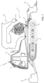
- Number 1 in Figure 1 indicates as a whole a crawler vehicle, which is a ski slope groomer.
- Crawler vehicle 1 comprises a frame 2; a track 3 ( Figure 2 ); a track 4; a drive wheel 5 ( Figure 2 ) and a drive wheel 6 independent of each other and connected to track 3 ( Figure 2 ) and track 4 respectively; a user interface 8; a cab 9; and a control device 10 ( Figure 2 ) communicating with user interface 8.
- FIG 2 ( Figure 2 ); a track 4; a drive wheel 5 ( Figure 2 ) and a drive wheel 6 independent of each other and connected to track 3 ( Figure 2 ) and track 4 respectively; a user interface 8; a cab 9; and a control device 10 ( Figure 2 ) communicating with user interface 8.
- Crawler vehicle 1 comprises an accessories assembly 11 comprising a tiller 12, a blade 13, and a winch 14.
- crawler vehicle 1 comprises an internal combustion engine 15, preferably a diesel engine; and a mechanical power transmission assembly 16 and electric power transmission assembly 17 for connecting internal combustion engine 15 to drive wheels 5, 6 and to accessories assembly 11 ( Figure 1 ).
- Control device 10 communicates with internal combustion engine 15 to control its power output.
- Mechanical power transmission assembly 16 comprises two shafts 20, 21, a gear train 22, a mechanical member 23, two axle shafts 24, 25, and two mechanical power transmissions 26, 27.
- Electric power transmission assembly 17 comprises five electric machines 30, 31, 32, 33, 34; an electric transmission line 35; and five actuating devices 36, 37, 38, 39, 40, which are connected electrically to respective electric machines 30, 31, 32, 33, 34, define an actuating device assembly, and communicate with control device 10.
- Crawler vehicle 1 comprises a variable resistor 41 and a switch 41a, both connected electrically to electric transmission line 35. And control device 10 communicates with switch 41a to connect variable resistor 41 to electric transmission line 35, and communicates with variable resistor 41 to control the impedance of variable resistor 41.
- Shaft 20 connects, and so transfers kinetic energy from, internal combustion engine 15 to gear train 22, which, in the example shown, is an epicyclic gear train 45 comprising a carrier 46, a sun gear 47, and a ring gear 48.
- Shaft 20 is connected mechanically to carrier 46 of epicyclic gear train 45; electric machine 30 is connected mechanically to sun gear 47 of epicyclic gear train 45; and shaft 21 is connected mechanically at one end to ring gear 48 of epicyclic gear train 45, and at the other end to mechanical member 23, which in turn is connected mechanically, to transfer power, to both drive wheels 5 and 6.
- mechanical member 23 is connected mechanically to drive wheel 5 by axle shaft 24, and to drive wheel 6 by axle shaft 25, and comprises a differential 23a for transferring kinetic energy from shaft 21 to axle shafts 24, 25.
- Axle shaft 24 comprises two axle shaft portions 24a and 24b, between which mechanical power transmission 26 is interposed and connected mechanically to electric machine 31 to receive/supply kinetic energy from/to electric machine 31.
- axle shaft 25 comprises two axle shaft portions 25a and 25b, between which mechanical power transmission 27 is interposed and connected mechanically to electric machine 32 to receive/supply kinetic energy from/to electric machine 32.
- Each of mechanical power transmissions 26 and 27 may be a gear train, or a cog belt drive, or a chain drive.
- Electric machine 30 and actuating device 36 are designed so that electric machine 30 operates as an electric generator or electric motor.
- electric machine 30 When operated as an electric generator, electric machine 30 is driven by sun gear 47 of epicyclic gear train 45, and supplies electric power to electric machines 31, 32, 33 and 34 over electric transmission line 35.
- electric machine 30 When operated as an electric motor, electric machine 30 is powered electrically by electric transmission line 35, and supplies kinetic energy to gear train 22 by means of sun gear 47. In which case, the kinetic energy may be used to power shaft 21, and therefore drive wheels 5 and 6; or to power shaft 20 to start internal combustion engine 15.
- Electric machine 33 is connected electrically to electric transmission line 35, and mechanically to tiller 12 to transfer kinetic energy to tiller 12; and electric machine 34 is connected electrically to electric transmission line 35, and mechanically to winch 14 to transfer kinetic energy to winch 14.
- Electric machines 31 and 32 are connected electrically to electric machine 30 by electric transmission line 35; electric machine 31 is connected mechanically to drive wheel 5 by mechanical power transmission 26; and electric machine 32 is connected mechanically to drive wheel 6 by mechanical power transmission 27.
- gear train 22 defines a mechanical power connection to transfer energy from/to electric power transmission assembly 17.
- the mechanical power connection is defined by sun gear 47.
- control device 10 When starting and running crawler vehicle 1 at low travelling speed (up to roughly 5 km/h), control device 10 acts on the actuating device assembly so that the power from internal combustion engine 15 is supplied mostly or entirely to electric machine 30, and only a small part or none at all to mechanical member 23. More specifically, control device 10 acts on actuating device 36 to regulate the resisting torque applied to sun gear 47 by electric machine 30. Electric machines 31, 32 receive electric power from electric machine 30, and power respective drive wheels 5 and 6 via respective mechanical power transmissions 26 and 27. Performance and consumption of crawler vehicle 1 is thus optimized by electric machines 31 and 32, which provide for high torque at low engine speed, and allow internal combustion engine 15 to operate independently of the travelling speed of crawler vehicle 1 and so reduce vehicle consumption.
- control device 10 acts on the actuating device assembly so that the kinetic energy from internal combustion engine 15 is distributed mostly or entirely to mechanical member 23, and only a small part or none at all to electric machine 30. More specifically, control device 10 acts on actuating device 36 to regulate the resisting torque applied to sun gear 47 by electric machine 30, so that internal combustion engine 15 mainly powers drive wheels 5 and 6 via gear train 22 and mechanical member 23. That is, the power from internal combustion engine 15 is supplied directly to drive wheels 5 and 6, with no further power conversion.
- control device 10 acts on the actuating device assembly to share the power from internal combustion engine 15 between mechanical member 23 and electric machine 30 according to a given equation which takes into account the travelling speed of crawler vehicle 1.
- the given equation may be an exponential power share, whereby the power share supplied directly to mechanical member 23 increases, and hence the power share supplied to electric machine 30 decreases, exponentially as the travelling speed of crawler vehicle 1 increases.
- the given equation may be a directly proportional power share, whereby the power share supplied directly to mechanical member 23 increases, and hence the power share supplied to electric machine 30 decreases, in direct proportion to an increase in the travelling speed of crawler vehicle 1.
- drive wheels 5 and 6 are powered mainly by electric machines 31 and 32, and, at high speed, mainly by mechanical member 23, i.e. directly by internal combustion engine 15, with no power conversion.
- mechanical member 23 i.e. directly by internal combustion engine 15, with no power conversion.
- the power drawn by electric machine 30 decreases, and the power drawn by mechanical member 23 increases, so less power is supplied to electric machines 31 and 32, and more power is supplied to mechanical member 23.
- power to drive wheels 5 and 6 is supplied by both mechanical member 23 and electric machines 31, 32, so electric power transmission assembly 17 and mechanical power transmission assembly 16 operate "parallel" along at least a portion of mechanical power transmission assembly 16.
- Electric power transmission assembly 17 and mechanical power transmission assembly 16 therefore transfer energy simultaneously or alternately to drive wheels 5 and 6. More specifically, at high speed, electric power transmission assembly 17 is substantially idle as regards driving crawler vehicle 1; at low speed, mechanical power transmission assembly 16 is at least partly idle; and, at intermediate speeds, mechanical power transmission assembly 16 and electric power transmission assembly 17 are both active simultaneously.
- Electric machines 31 and 32 can be run independently to control turning of crawler vehicle 1.
- control device 10 controlling the actuating device assembly - in particular, actuating devices 36 and 37 - to change the rotor speed of electric machine 31 with respect to that of electric machine 32.
- control device 10 controls actuating device 37 and/or actuating device 38 to reduce the rotor speed of electric machine 31 with respect to that of electric machine 32, and vice versa.
- the power generated by electric machine 31 or 32 is supplied to electric machine 30, which generates and supplies kinetic energy to gear train 22 via sun gear 47.
- control device 10 when turning, controls device 10 acts on electric machine 32 or 31 so that it operates as an electric motor, i.e. supplies kinetic energy to mechanical power transmission 27 or 26, and the electric power generated by electric machine 31 or 32 powers electric machine 32 or 31.
- variable resistor 41 when turning, the electric power generated by electric machine 31 or 32 is dissipated by variable resistor 41.
- control device 10 acts on the actuating device assembly so that the power from internal combustion engine 15 is supplied entirely to electric machine 30, and none to mechanical member 23; and electric power is transferred to electric machines 31 and 32 over electric transmission line 35, so drive wheels 5 and 6 are powered solely by electric power transmission assembly 17, and in particular by electric machines 31 and 32.
- shaft 21 is fitted with a reverser 50 (shown by the dash block in Figure 2 ) designed to invert rotation of shaft 21, so that, when travelling in reverse, kinetic energy is also transferred to drive wheels 5 and 6 by shaft 21 in the same way as when travelling forward.
- a reverser 50 shown by the dash block in Figure 2
Landscapes
- Engineering & Computer Science (AREA)
- Transportation (AREA)
- Mechanical Engineering (AREA)
- Chemical & Material Sciences (AREA)
- Combustion & Propulsion (AREA)
- Power Engineering (AREA)
- Arrangement Of Transmissions (AREA)
- Arrangement Or Mounting Of Propulsion Units For Vehicles (AREA)
- Electric Propulsion And Braking For Vehicles (AREA)
- Arrangement And Driving Of Transmission Devices (AREA)
- Hybrid Electric Vehicles (AREA)
Description
- The present invention relates to a ski slope groomer and relative control method.
- More specifically, the present invention relates to a ski slope groomer comprising a first and second track; an internal combustion engine; a power transmission for connecting the first and second track to the internal combustion engine; a plurality of implements connected to the internal combustion engine by the power transmission; and a user interface.
- A crawler vehicle of the above type is known from
EP 0895495 B1 . - The power transmission between the internal combustion engine and the demand assembly may be predominantly electric or electric, as described in
WO 94/09548 US 5363937 andWO 92/08278 -
EP 1 747 929 discloses an hybrid drive for a crawler vehicle or a tank comprising a drive shaft moving the track sprockets and at least one differential arrangement transferring the speed of the drive to at least one of the track sprockets. The drive shaft is connected to at least one electric drive unit designed as a motor or a generator. The drive shafts of the combustion engine and the electric motor are coupled with an overlapping transmission unit. The electric drives can be used as brake units transforming the kinetic energy of the vehicle into electric energy to be saved in a battery when driving downhill. - The electric power transmission normally comprises a first electric machine, in particular an electric generator; at least one second electric machine, in particular an electric motor; and an electric transmission line.
- The internal combustion engine is connected by a shaft to the electric generator, which receives kinetic energy from the internal combustion engine and converts it to electric energy; and the electric motor receives electric energy from the electric generator via the electric transmission line, and converts it to kinetic energy.
- Crawler vehicles with electric power transmissions are more efficient that hydraulic-transmission types, and also have the advantage, afforded by electric machines, of high torque at low engine speed. The efficiency of the vehicle, however, is not always fully satisfactory in all engine speed conditions.
- It is an object of the present invention to enhance the efficiency of known ski slope groomer in terms of energy consumption.
- According to the present invention, there is provided a ski slope groomer according to claim 1.
- By virtue of the mechanical power transmission assembly extending from the internal combustion engine to the first and second drive wheel, and to the electric power transmission assembly extending from the mechanical power connection to the mechanical power transmission, it is possible to enhance the efficiency of the ski slope groomer in any engine speed condition.
- Another object of the present invention is to provide a ski slope groomer control method designed to enhance vehicle efficiency.
- According to the present invention, there is provided a method of controlling a ski slope groomer according to
claim 15. - A non-limiting embodiment of the present invention will be described by way of example with reference to the accompanying drawings, in which :
-
Figure 1 shows a side view, with parts removed for clarity, of a vehicle in accordance with the present invention; -
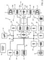
Figure 2 shows a block diagram of theFigure 1 vehicle. - Number 1 in
Figure 1 indicates as a whole a crawler vehicle, which is a ski slope groomer. - Crawler vehicle 1 comprises a
frame 2; a track 3 (Figure 2 ); atrack 4; a drive wheel 5 (Figure 2 ) and adrive wheel 6 independent of each other and connected to track 3 (Figure 2 ) andtrack 4 respectively; a user interface 8; a cab 9; and a control device 10 (Figure 2 ) communicating with user interface 8. - (
Figure 2 ); atrack 4; a drive wheel 5 (Figure 2 ) and adrive wheel 6 independent of each other and connected to track 3 (Figure 2 ) andtrack 4 respectively; a user interface 8; a cab 9; and a control device 10 (Figure 2 ) communicating with user interface 8. - Crawler vehicle 1 comprises an
accessories assembly 11 comprising atiller 12, ablade 13, and awinch 14. - With reference to
Figure 2 , crawler vehicle 1 comprises aninternal combustion engine 15, preferably a diesel engine; and a mechanicalpower transmission assembly 16 and electricpower transmission assembly 17 for connectinginternal combustion engine 15 to drivewheels 5, 6 and to accessories assembly 11 (Figure 1 ). -
Control device 10 communicates withinternal combustion engine 15 to control its power output. - Mechanical
power transmission assembly 16 comprises twoshafts gear train 22, amechanical member 23, twoaxle shafts mechanical power transmissions - Electric
power transmission assembly 17 comprises fiveelectric machines electric transmission line 35; and fiveactuating devices electric machines control device 10. - Crawler vehicle 1 comprises a
variable resistor 41 and aswitch 41a, both connected electrically toelectric transmission line 35. Andcontrol device 10 communicates withswitch 41a to connectvariable resistor 41 toelectric transmission line 35, and communicates withvariable resistor 41 to control the impedance ofvariable resistor 41. - Shaft 20 connects, and so transfers kinetic energy from,
internal combustion engine 15 togear train 22, which, in the example shown, is anepicyclic gear train 45 comprising acarrier 46, asun gear 47, and aring gear 48. Shaft 20 is connected mechanically tocarrier 46 ofepicyclic gear train 45;electric machine 30 is connected mechanically tosun gear 47 ofepicyclic gear train 45; andshaft 21 is connected mechanically at one end toring gear 48 ofepicyclic gear train 45, and at the other end tomechanical member 23, which in turn is connected mechanically, to transfer power, to bothdrive wheels 5 and 6. - More specifically,
mechanical member 23 is connected mechanically to drive wheel 5 byaxle shaft 24, and to drivewheel 6 byaxle shaft 25, and comprises a differential 23a for transferring kinetic energy fromshaft 21 toaxle shafts -
Axle shaft 24 comprises twoaxle shaft portions mechanical power transmission 26 is interposed and connected mechanically toelectric machine 31 to receive/supply kinetic energy from/toelectric machine 31. - Likewise,
axle shaft 25 comprises twoaxle shaft portions mechanical power transmission 27 is interposed and connected mechanically toelectric machine 32 to receive/supply kinetic energy from/toelectric machine 32. - Each of
mechanical power transmissions -
Electric machine 30 and actuatingdevice 36 are designed so thatelectric machine 30 operates as an electric generator or electric motor. When operated as an electric generator,electric machine 30 is driven bysun gear 47 ofepicyclic gear train 45, and supplies electric power toelectric machines electric transmission line 35. When operated as an electric motor,electric machine 30 is powered electrically byelectric transmission line 35, and supplies kinetic energy togear train 22 by means ofsun gear 47. In which case, the kinetic energy may be used to powershaft 21, and therefore drivewheels 5 and 6; or topower shaft 20 to startinternal combustion engine 15. -
Electric machine 33 is connected electrically toelectric transmission line 35, and mechanically to tiller 12 to transfer kinetic energy to tiller 12; andelectric machine 34 is connected electrically toelectric transmission line 35, and mechanically to winch 14 to transfer kinetic energy to winch 14. -
Electric machines electric machine 30 byelectric transmission line 35;electric machine 31 is connected mechanically to drive wheel 5 bymechanical power transmission 26; andelectric machine 32 is connected mechanically to drivewheel 6 bymechanical power transmission 27. - In actual use,
gear train 22 defines a mechanical power connection to transfer energy from/to electricpower transmission assembly 17. - More specifically, the mechanical power connection is defined by
sun gear 47. - When starting and running crawler vehicle 1 at low travelling speed (up to roughly 5 km/h),
control device 10 acts on the actuating device assembly so that the power frominternal combustion engine 15 is supplied mostly or entirely toelectric machine 30, and only a small part or none at all tomechanical member 23. More specifically,control device 10 acts on actuatingdevice 36 to regulate the resisting torque applied tosun gear 47 byelectric machine 30.Electric machines electric machine 30, and powerrespective drive wheels 5 and 6 via respectivemechanical power transmissions electric machines internal combustion engine 15 to operate independently of the travelling speed of crawler vehicle 1 and so reduce vehicle consumption. - At high travelling speed (roughly 25 km/h),
control device 10 acts on the actuating device assembly so that the kinetic energy frominternal combustion engine 15 is distributed mostly or entirely tomechanical member 23, and only a small part or none at all toelectric machine 30. More specifically,control device 10 acts on actuatingdevice 36 to regulate the resisting torque applied tosun gear 47 byelectric machine 30, so thatinternal combustion engine 15 mainly powersdrive wheels 5 and 6 viagear train 22 andmechanical member 23. That is, the power frominternal combustion engine 15 is supplied directly to drivewheels 5 and 6, with no further power conversion. - At speeds between high and low travelling speed,
control device 10 acts on the actuating device assembly to share the power frominternal combustion engine 15 betweenmechanical member 23 andelectric machine 30 according to a given equation which takes into account the travelling speed of crawler vehicle 1. The given equation, for example, may be an exponential power share, whereby the power share supplied directly tomechanical member 23 increases, and hence the power share supplied toelectric machine 30 decreases, exponentially as the travelling speed of crawler vehicle 1 increases. - By way of another example, the given equation may be a directly proportional power share, whereby the power share supplied directly to
mechanical member 23 increases, and hence the power share supplied toelectric machine 30 decreases, in direct proportion to an increase in the travelling speed of crawler vehicle 1. - In other words, at startup,
drive wheels 5 and 6 are powered mainly byelectric machines mechanical member 23, i.e. directly byinternal combustion engine 15, with no power conversion. At intermediate speeds, as speed increases from startup to maximum speed, the power drawn byelectric machine 30 decreases, and the power drawn bymechanical member 23 increases, so less power is supplied toelectric machines mechanical member 23. It is important to note that, over most of the operating speed range of crawler vehicle 1, power to drivewheels 5 and 6 is supplied by bothmechanical member 23 andelectric machines power transmission assembly 17 and mechanicalpower transmission assembly 16 operate "parallel" along at least a portion of mechanicalpower transmission assembly 16. - Electric
power transmission assembly 17 and mechanicalpower transmission assembly 16 therefore transfer energy simultaneously or alternately to drivewheels 5 and 6. More specifically, at high speed, electricpower transmission assembly 17 is substantially idle as regards driving crawler vehicle 1; at low speed, mechanicalpower transmission assembly 16 is at least partly idle; and, at intermediate speeds, mechanicalpower transmission assembly 16 and electricpower transmission assembly 17 are both active simultaneously. -
Electric machines - At low speed, when power is transmitted mainly by electric
power transmission assembly 17, turning is controlled bycontrol device 10 controlling the actuating device assembly - in particular, actuatingdevices 36 and 37 - to change the rotor speed ofelectric machine 31 with respect to that ofelectric machine 32. For example, to turn right,control device 10 controls actuatingdevice 37 and/or actuatingdevice 38 to reduce the rotor speed ofelectric machine 31 with respect to that ofelectric machine 32, and vice versa. - At intermediate or high speed, at which drive
wheels 5 and 6 are powered mainly bymechanical member 23, turning is controlled bycontrol device 10 acting on actuatingdevices electric machine mechanical power transmission axle shaft - The power generated by
electric machine electric machine 30, which generates and supplies kinetic energy togear train 22 viasun gear 47. - In an alternative version of the present invention, when turning,
control device 10 acts onelectric machine mechanical power transmission electric machine electric machine - In these cases, turning is performed with very little power dissipation, caused solely by parasitic Joule-effect losses, with no other power wastage, on account of kinetic energy being drawn on the one hand, and supplied on the other, thus enhancing the efficiency of crawler vehicle 1 with respect to the known art.
- In an alternative version of the present invention, when turning, the electric power generated by
electric machine variable resistor 41. - When reversing crawler vehicle 1,
control device 10 acts on the actuating device assembly so that the power frominternal combustion engine 15 is supplied entirely toelectric machine 30, and none tomechanical member 23; and electric power is transferred toelectric machines electric transmission line 35, so drivewheels 5 and 6 are powered solely by electricpower transmission assembly 17, and in particular byelectric machines - In an alternative version of the present invention,
shaft 21 is fitted with a reverser 50 (shown by the dash block inFigure 2 ) designed to invert rotation ofshaft 21, so that, when travelling in reverse, kinetic energy is also transferred to drivewheels 5 and 6 byshaft 21 in the same way as when travelling forward. - The advantages of the present invention in terms of enhancing the efficiency of the crawler vehicle will be clear from the above description.
- The present invention obviously also covers embodiments not described in detail herein, as well as equivalent embodiments within the protective scope of the accompanying Claims.
Claims (20)
- A ski slope groomer (1) comprising:- a first and second track (3, 4) driven by a first and second drive wheel (5, 6) respectively;- an accessory assembly (11) comprising a tiller (12) and a blade (13), and preferably a winch (14);- an internal combustion engine (15); and- electric power transmission assembly (17) and a mechanical power transmission assembly (16) for connecting the internal combustion engine (15) to the first and second drive wheel (5, 6); the mechanical power transmission assembly comprising:- a mechanical power connection (22) for transferring energy between the electric power transmission assembly (17) and the mechanical power transmission assembly (16);- and at least one mechanical power transmission (26, 27) for transferring energy between the electric power transmission assembly (17) and the mechanical power transmission assembly (16); and wherein the electric power transmission assembly (17) extends from the mechanical power connection (22) to the mechanical power transmission (26, 27);the ski slope groomer comprising a third electric machine (33) connected electrically to an electric transmission line (35), and mechanically to tiller (12) to transfer kinetic energy to tiller (12); preferably the ski slope groomer (1) comprising a fourth electric machine (34) is connected electrically to the electric transmission line (35), and mechanically to winch (14) to transfer kinetic energy to winch (14).
- A ski slope groomer as claimed in Claim 1, wherein the electric power transmission assembly (17) is parallel to a portion of the mechanical power transmission assembly (16) .
- A ski slope groomer as claimed in Claim 1 or 2, wherein the mechanical power transmission assembly (16) and the electric power transmission assembly (17) are designed to transfer energy simultaneously or alternately to the first and second drive wheel (5, 6).
- A ski slope groomer as claimed in any one of the foregoing Claims, wherein the mechanical power transmission assembly (16) comprises a mechanical member (23) for driving the drive wheels (5, 6); a first gear train (22), which defines said mechanical power connection and is designed to share the energy from the internal combustion engine (15) between the mechanical member (23) and the electric power transmission assembly (17); and a first shaft (20) for connecting the internal combustion engine (15) to the first gear train (22).
- A ski slope groomer as claimed in Claim 4, wherein the mechanical power transmission assembly (16) comprises a second shaft (21) for connecting the first gear train (22) to the mechanical member (23); and the second shaft (21) is interposed between the first or second drive wheel (5, 6) and the first gear train (22).
- A ski slope groomer as claimed in Claim 4 or 5, wherein the first gear train (22) is an epicyclic gear train (45) .
- A ski slope groomer as claimed in Claim 6, wherein the electric power transmission assembly (17) comprises a first electric machine (30); the epicyclic gear train (45) comprising a sun gear (47) connected mechanically to the first electric machine (30).
- A ski slope groomer as claimed in Claim 6 or 7, wherein the epicyclic gear train (45) comprises a carrier (46) connected mechanically to the internal combustion engine (15); and a ring gear (48) connected mechanically to the first and second drive wheel (5, 6).
- A ski slope groomer as claimed in any one of the foregoing Claims, wherein the electric power transmission assembly (17) comprises a first electric machine (30) connected mechanically to the mechanical power connection; and two second electric machines (31, 32) connected mechanically and independently to the first and second drive wheel (5, 6) respectively, and connected electrically to the first electric machine (30).
- A ski slope groomer as claimed in Claim 9, wherein the mechanical power transmission (26, 27) is designed to mechanically and independently connect the first or second electric machine (31, 32) to the first or second drive wheel (5, 6) respectively.
- A ski slope groomer as claimed in any one of the foregoing Claims, wherein the electric power transmission assembly (17) comprises a first electric machine (30) connected mechanically to the internal combustion engine (15); and a first actuating device (36) for operating the first electric machine (30); the crawler vehicle (1) comprising a control device (10) for controlling the first actuating device (36) to share the energy from the internal combustion engine (15) between the mechanical power transmission assembly (16) and the electric power transmission assembly (17) on the basis of the travelling speed of the crawler vehicle (1).
- A ski slope groomer as claimed in Claim 11, wherein the electric power transmission assembly (17) comprises two second electric machines (31, 32) connected mechanically to the first and second drive wheel (5, 6) respectively; and two second actuating devices (37, 38) for operating the second electric machines (31, 32); and the control device (10) is designed to control the two second actuating devices (37, 38) to share the energy from the electric power transmission assembly (17) between the two second electric machines (31, 32).
- A ski slope groomer as claimed in Claim 12, wherein the control device (10) is designed to control one of the two second actuating devices (37, 38) so that one of the second electric machines (31, 32) operates as an electric generator.
- A ski slope groomer as claimed in Claim 13, wherein the control device (10) is designed to control the other of the two second actuating devices (38, 37) or the first actuating device (36) so that the other of the second electric machines (32, 31) or the first electric machine (30) operates as an electric motor and is powered by one of the second electric machines (31, 32).
- A method of controlling a ski slope groomer; the ski slope groomer comprising:- a first and second track (3, 4) driven by a first and second drive wheel (5, 6) respectively;- an accessory assembly (11) comprising a tiller (12), and a blade (13) and preferably a winch (14);- an internal combustion engine (15);- and an electric power transmission assembly (17) and a mechanical power transmission assembly (16) for connecting the internal combustion engine (15) to the first and second drive wheel (5, 6); the mechanical power transmission assembly comprising a mechanical power connection; and at least one mechanical power transmission (26, 27);the ski slope groomer comprising a third electric machine (33) connected electrically to an electric transmission line (35), and mechanically to tiller (12) to transfer kinetic energy to tiller (12); preferably the ski slope groomer (1) comprising a fourth electric machine (34) connected electrically to the electric transmission line (35), and mechanically to winch (14) to transfer kinetic energy to winch (14);the method comprising the steps of transferring energy between the mechanical power transmission assembly (16) and the electric power transmission assembly (17) by means of the mechanical power connection (22); and transferring energy between the electric power transmission assembly (17) and the mechanical power transmission assembly (16) by means of the mechanical power transmission (26, 27).
- A method as claimed in Claim 15, and comprising the step of alternately or simultaneously transferring energy from the internal combustion engine (15) to the first and second drive wheel (5, 6) by means of the mechanical power transmission assembly (16) and the electric power transmission assembly (17).
- A method as claimed in Claim 15 or 16, wherein the mechanical power transmission assembly (16) comprises a mechanical member (23) for transferring mechanical energy from the internal combustion engine (15) to the first and second track (3, 4); the method comprising the step of sharing the energy from the internal combustion engine (15) between the mechanical member (23) and the electric power transmission assembly (17) on the basis of the travelling speed of the crawler vehicle (1).
- A method as claimed in one of Claims 15 to 17, wherein the electric power transmission assembly (17) comprises a first electric machine (30) connected mechanically to the internal combustion engine (15); and two second electric machines (31, 32) connected mechanically to the first and second drive wheel (5, 6) and electrically to the first electric machine (30); the method comprising the step of transferring energy independently to the first and second drive wheel (5, 6) by means of the second electric machines (31, 32) respectively; and preferably comprising the step of transferring energy from the internal combustion engine (15) to the first electric machine (30).
- A method as claimed in Claim 18, and comprising the steps of generating electric energy by means of one of the second electric machines (31, 32).
- A method as claimed in Claim 19, and comprising the step of powering the other of the second electric machines (32, 31) or the first electric machine (30) with the electric energy generated by said one of the second electric machines (31, 32).
Priority Applications (1)
| Application Number | Priority Date | Filing Date | Title |
|---|---|---|---|
| EP17211196.5A EP3323696A1 (en) | 2010-12-22 | 2011-12-22 | Crawler vehicle and relative control method |
Applications Claiming Priority (2)
| Application Number | Priority Date | Filing Date | Title |
|---|---|---|---|
| ITMI2010A002358A IT1403609B1 (en) | 2010-12-22 | 2010-12-22 | TRACKED VEHICLE AND METHOD OF CONTROL OF THE SAME |
| PCT/IB2011/055917 WO2012085882A1 (en) | 2010-12-22 | 2011-12-22 | Crawler vehicle and relative control method |
Related Child Applications (2)
| Application Number | Title | Priority Date | Filing Date |
|---|---|---|---|
| EP17211196.5A Division-Into EP3323696A1 (en) | 2010-12-22 | 2011-12-22 | Crawler vehicle and relative control method |
| EP17211196.5A Division EP3323696A1 (en) | 2010-12-22 | 2011-12-22 | Crawler vehicle and relative control method |
Publications (3)
| Publication Number | Publication Date |
|---|---|
| EP2655165A1 EP2655165A1 (en) | 2013-10-30 |
| EP2655165B1 EP2655165B1 (en) | 2018-01-24 |
| EP2655165B2 true EP2655165B2 (en) | 2025-01-15 |
Family
ID=43737011
Family Applications (2)
| Application Number | Title | Priority Date | Filing Date |
|---|---|---|---|
| EP17211196.5A Pending EP3323696A1 (en) | 2010-12-22 | 2011-12-22 | Crawler vehicle and relative control method |
| EP11820805.7A Active EP2655165B2 (en) | 2010-12-22 | 2011-12-22 | Ski slope groomer and relative control method |
Family Applications Before (1)
| Application Number | Title | Priority Date | Filing Date |
|---|---|---|---|
| EP17211196.5A Pending EP3323696A1 (en) | 2010-12-22 | 2011-12-22 | Crawler vehicle and relative control method |
Country Status (5)
| Country | Link |
|---|---|
| US (1) | US9975417B2 (en) |
| EP (2) | EP3323696A1 (en) |
| CA (1) | CA2822587C (en) |
| IT (1) | IT1403609B1 (en) |
| WO (1) | WO2012085882A1 (en) |
Families Citing this family (5)
| Publication number | Priority date | Publication date | Assignee | Title |
|---|---|---|---|---|
| SE542381C2 (en) * | 2012-04-23 | 2020-04-21 | Brokk Ab | Electrically powered demolition robot and its power supply system |
| CN103434567B (en) * | 2013-08-21 | 2016-01-13 | 河南科技大学 | Continuously tracked vehicle craspedodrome, rotating direction control method and steering hardware and continuous turning system |
| DE102019206459A1 (en) * | 2019-05-06 | 2020-11-12 | Kässbohrer Geländefahrzeug Aktiengesellschaft | Snowcat |
| IT202000013378A1 (en) * | 2020-06-05 | 2021-12-05 | Prinoth Spa | TRACKED VEHICLE, METHOD OF CONTROL AND PROGRAM FOR THE ELECTRONIC COMPUTER OF SUCH VEHICLE |
| DE102024108900A1 (en) * | 2024-03-28 | 2025-10-02 | Kässbohrer Geländefahrzeug Aktiengesellschaft | Snowcat with a tracked chassis |
Citations (2)
| Publication number | Priority date | Publication date | Assignee | Title |
|---|---|---|---|---|
| US1984830A (en) † | 1933-05-05 | 1934-12-18 | Frank R Higley | Vehicle drive |
| WO2003035422A1 (en) † | 2001-10-23 | 2003-05-01 | The Timken Company | Output power split hybrid electric drive system |
Family Cites Families (29)
| Publication number | Priority date | Publication date | Assignee | Title |
|---|---|---|---|---|
| US4405029A (en) * | 1980-01-02 | 1983-09-20 | Hunt Hugh S | Hybrid vehicles |
| US4470476A (en) * | 1981-11-16 | 1984-09-11 | Hunt Hugh S | Hybrid vehicles |
| US5120282A (en) * | 1990-10-16 | 1992-06-09 | Fjaellstroem Bengt | Vehicle transmission system |
| US5162707A (en) | 1990-10-24 | 1992-11-10 | Fmc Corporation | Induction motor propulsion system for powering and steering vehicles |
| US5301764A (en) * | 1992-04-13 | 1994-04-12 | Gardner Conrad O | Hybrid motor vehicle having an electric motor and utilizing an internal combustion engine for fast charge during cruise mode off condition |
| DE4217668C1 (en) * | 1992-05-28 | 1993-05-06 | Daimler Benz Ag | Method for controlling a hybrid drive that drives a vehicle |
| WO1994009548A1 (en) | 1992-10-19 | 1994-04-28 | Lmc Operating Corp. | Electric operated tracked vehicle |
| US5363937A (en) | 1992-10-19 | 1994-11-15 | Lmc Operating Corp. | Battery operated tracked vehicle |
| JP3291916B2 (en) * | 1994-06-06 | 2002-06-17 | 株式会社エクォス・リサーチ | Hybrid vehicle |
| DE29607651U1 (en) * | 1996-04-26 | 1997-08-28 | Kässbohrer Geländefahrzeug AG, 89250 Senden | Tracked vehicle |
| EP1038346A2 (en) * | 1997-10-21 | 2000-09-27 | Stridsberg Innovation Ab | A hybrid powertrain |
| US6573745B2 (en) * | 2001-05-04 | 2003-06-03 | Ford Global Technologies, Inc. | Permanent magnet degradation monitoring for hybrid and electric vehicles |
| US7140461B2 (en) * | 2003-11-26 | 2006-11-28 | Oshkosh Truck Corporation | Power splitting vehicle drive system |
| DE102005035824A1 (en) * | 2005-07-30 | 2007-02-01 | Renk Ag | Hybrid drive for a motor vehicle |
| US7950481B2 (en) * | 2005-09-29 | 2011-05-31 | Caterpillar Inc. | Electric powertrain for machine |
| EP2097283A2 (en) * | 2006-10-13 | 2009-09-09 | The Ohio State University Research Foundation | Powertrain, vehicle and methods |
| JP5128866B2 (en) * | 2007-07-10 | 2013-01-23 | 株式会社アツミテック | Vehicle propulsion device |
| FR2922163B1 (en) * | 2007-10-10 | 2010-02-26 | Inst Francais Du Petrole | MOVING DRIVE SYSTEM WITH MULTIPLE TRANSMISSION PATHS FOR A HYBRID VEHICLE AND METHOD FOR TRAINING IN DISPLACEMENT OF SAID VEHICLE |
| US8360185B2 (en) * | 2008-02-14 | 2013-01-29 | Mitsuba Corporation | Hybrid electric automobile |
| GB2466081B (en) * | 2008-12-15 | 2010-11-17 | Etv Motors Ltd | Cooling for hybrid electric vehicle |
| DE102009004023B4 (en) * | 2009-01-08 | 2018-07-12 | Knorr-Bremse Systeme für Nutzfahrzeuge GmbH | A method for controlling a start-stop operation of a hybrid drive vehicle and a corresponding vehicle |
| US8346421B2 (en) * | 2009-03-24 | 2013-01-01 | Ford Global Technologies, Llc | Method and system for initiating starting of an engine in a hybrid electric vehicle |
| US8083016B2 (en) * | 2009-04-13 | 2011-12-27 | GM Global Technology Operations LLC | Vehicle with hybrid powertrain |
| US8386104B2 (en) * | 2009-06-01 | 2013-02-26 | Ford Global Technologies, Llc | System and method for displaying power flow in a hybrid vehicle |
| KR101360698B1 (en) * | 2009-06-09 | 2014-02-07 | 스미도모쥬기가이고교 가부시키가이샤 | Hybrid excavator and controlling method therefor |
| JP5550064B2 (en) * | 2009-07-01 | 2014-07-16 | 住友重機械工業株式会社 | Hybrid work machine |
| KR101112137B1 (en) * | 2009-07-29 | 2012-02-22 | 볼보 컨스트럭션 이큅먼트 에이비 | Control System and Method For Reducing Change Of RPM In Hybrid Type Construction Machine |
| US8403808B2 (en) * | 2010-03-25 | 2013-03-26 | Tai-Her Yang | Individual-powered dual CVT differential system with stabilizing device |
| US20110281679A1 (en) * | 2010-04-08 | 2011-11-17 | The Regents Of The University Of Colorado, A Body Corporate | Hybrid transmission using planetary gearset for multiple sources of torque for marine, or two wheeled land vehicles |
-
2010
- 2010-12-22 IT ITMI2010A002358A patent/IT1403609B1/en active
-
2011
- 2011-12-22 EP EP17211196.5A patent/EP3323696A1/en active Pending
- 2011-12-22 EP EP11820805.7A patent/EP2655165B2/en active Active
- 2011-12-22 WO PCT/IB2011/055917 patent/WO2012085882A1/en not_active Ceased
- 2011-12-22 US US13/995,369 patent/US9975417B2/en active Active
- 2011-12-22 CA CA2822587A patent/CA2822587C/en active Active
Patent Citations (2)
| Publication number | Priority date | Publication date | Assignee | Title |
|---|---|---|---|---|
| US1984830A (en) † | 1933-05-05 | 1934-12-18 | Frank R Higley | Vehicle drive |
| WO2003035422A1 (en) † | 2001-10-23 | 2003-05-01 | The Timken Company | Output power split hybrid electric drive system |
Also Published As
| Publication number | Publication date |
|---|---|
| IT1403609B1 (en) | 2013-10-31 |
| CA2822587A1 (en) | 2012-06-28 |
| EP2655165B1 (en) | 2018-01-24 |
| US20130333958A1 (en) | 2013-12-19 |
| EP2655165A1 (en) | 2013-10-30 |
| EP3323696A1 (en) | 2018-05-23 |
| US9975417B2 (en) | 2018-05-22 |
| WO2012085882A1 (en) | 2012-06-28 |
| ITMI20102358A1 (en) | 2012-06-23 |
| CA2822587C (en) | 2019-07-23 |
Similar Documents
| Publication | Publication Date | Title |
|---|---|---|
| US8261550B2 (en) | Power unit for an automotive vehicle and vehicle including such a power unit | |
| US7950481B2 (en) | Electric powertrain for machine | |
| EP2086781B1 (en) | Hybrid power output system | |
| EP2117868B1 (en) | Hybrid power output system | |
| US6935451B2 (en) | Axle assembly with parallel drive system for electric hybrid vehicles | |
| JP3350314B2 (en) | Hybrid vehicle drive system | |
| US20090288899A1 (en) | Vehicle with multiple engines coupled to a transmission via a jackshaft | |
| KR101302404B1 (en) | Electric vehicle for agriculture | |
| EP2655165B2 (en) | Ski slope groomer and relative control method | |
| JP5921773B2 (en) | Hybrid drive vehicle drive system | |
| SE0950530A1 (en) | Waist-mounted tape drive | |
| AU2008227949A1 (en) | Hybrid propulsion and transmission system for motorcycles | |
| SE529172C2 (en) | Tire drive device | |
| US8511410B2 (en) | Travel system for a hybrid type motor vehicle and method for driving same | |
| US20220134860A1 (en) | Hybrid agricultural vehicle | |
| US9010103B2 (en) | Device for driving working equipment of a commercial vehicle | |
| CN210390737U (en) | Double-power driving system of electric tractor | |
| CN208530275U (en) | Caterpillar | |
| KR101085976B1 (en) | Power train of hybrid electric vehicle | |
| US20260091668A1 (en) | Independent power split transfer drivetrain for electric vehicles and a method thereof | |
| KR20120009361A (en) | Vehicle shock reduction device | |
| SE1150959A1 (en) | Waist-mounted tape drive | |
| SE1150958A1 (en) | Waist-mounted tape drive | |
| SE1150957A1 (en) | Waist-mounted tape drive |
Legal Events
| Date | Code | Title | Description |
|---|---|---|---|
| PUAI | Public reference made under article 153(3) epc to a published international application that has entered the european phase |
Free format text: ORIGINAL CODE: 0009012 |
|
| 17P | Request for examination filed |
Effective date: 20130619 |
|
| AK | Designated contracting states |
Kind code of ref document: A1 Designated state(s): AL AT BE BG CH CY CZ DE DK EE ES FI FR GB GR HR HU IE IS IT LI LT LU LV MC MK MT NL NO PL PT RO RS SE SI SK SM TR |
|
| DAX | Request for extension of the european patent (deleted) | ||
| RAP1 | Party data changed (applicant data changed or rights of an application transferred) |
Owner name: PRINOTH S.P.A. |
|
| GRAP | Despatch of communication of intention to grant a patent |
Free format text: ORIGINAL CODE: EPIDOSNIGR1 |
|
| INTG | Intention to grant announced |
Effective date: 20160727 |
|
| GRAJ | Information related to disapproval of communication of intention to grant by the applicant or resumption of examination proceedings by the epo deleted |
Free format text: ORIGINAL CODE: EPIDOSDIGR1 |
|
| STAA | Information on the status of an ep patent application or granted ep patent |
Free format text: STATUS: REQUEST FOR EXAMINATION WAS MADE |
|
| INTC | Intention to grant announced (deleted) | ||
| GRAP | Despatch of communication of intention to grant a patent |
Free format text: ORIGINAL CODE: EPIDOSNIGR1 |
|
| STAA | Information on the status of an ep patent application or granted ep patent |
Free format text: STATUS: GRANT OF PATENT IS INTENDED |
|
| INTG | Intention to grant announced |
Effective date: 20170127 |
|
| GRAJ | Information related to disapproval of communication of intention to grant by the applicant or resumption of examination proceedings by the epo deleted |
Free format text: ORIGINAL CODE: EPIDOSDIGR1 |
|
| STAA | Information on the status of an ep patent application or granted ep patent |
Free format text: STATUS: REQUEST FOR EXAMINATION WAS MADE |
|
| INTC | Intention to grant announced (deleted) | ||
| GRAP | Despatch of communication of intention to grant a patent |
Free format text: ORIGINAL CODE: EPIDOSNIGR1 |
|
| STAA | Information on the status of an ep patent application or granted ep patent |
Free format text: STATUS: GRANT OF PATENT IS INTENDED |
|
| INTG | Intention to grant announced |
Effective date: 20170731 |
|
| GRAS | Grant fee paid |
Free format text: ORIGINAL CODE: EPIDOSNIGR3 |
|
| GRAA | (expected) grant |
Free format text: ORIGINAL CODE: 0009210 |
|
| STAA | Information on the status of an ep patent application or granted ep patent |
Free format text: STATUS: THE PATENT HAS BEEN GRANTED |
|
| AK | Designated contracting states |
Kind code of ref document: B1 Designated state(s): AL AT BE BG CH CY CZ DE DK EE ES FI FR GB GR HR HU IE IS IT LI LT LU LV MC MK MT NL NO PL PT RO RS SE SI SK SM TR |
|
| REG | Reference to a national code |
Ref country code: GB Ref legal event code: FG4D |
|
| REG | Reference to a national code |
Ref country code: CH Ref legal event code: EP |
|
| REG | Reference to a national code |
Ref country code: AT Ref legal event code: REF Ref document number: 965605 Country of ref document: AT Kind code of ref document: T Effective date: 20180215 |
|
| REG | Reference to a national code |
Ref country code: IE Ref legal event code: FG4D |
|
| REG | Reference to a national code |
Ref country code: DE Ref legal event code: R096 Ref document number: 602011045368 Country of ref document: DE |
|
| REG | Reference to a national code |
Ref country code: CH Ref legal event code: NV Representative=s name: HEPP WENGER RYFFEL AG, CH |
|
| REG | Reference to a national code |
Ref country code: NL Ref legal event code: MP Effective date: 20180124 |
|
| REG | Reference to a national code |
Ref country code: LT Ref legal event code: MG4D |
|
| PG25 | Lapsed in a contracting state [announced via postgrant information from national office to epo] |
Ref country code: NL Free format text: LAPSE BECAUSE OF FAILURE TO SUBMIT A TRANSLATION OF THE DESCRIPTION OR TO PAY THE FEE WITHIN THE PRESCRIBED TIME-LIMIT Effective date: 20180124 |
|
| PG25 | Lapsed in a contracting state [announced via postgrant information from national office to epo] |
Ref country code: ES Free format text: LAPSE BECAUSE OF FAILURE TO SUBMIT A TRANSLATION OF THE DESCRIPTION OR TO PAY THE FEE WITHIN THE PRESCRIBED TIME-LIMIT Effective date: 20180124 Ref country code: NO Free format text: LAPSE BECAUSE OF FAILURE TO SUBMIT A TRANSLATION OF THE DESCRIPTION OR TO PAY THE FEE WITHIN THE PRESCRIBED TIME-LIMIT Effective date: 20180424 Ref country code: HR Free format text: LAPSE BECAUSE OF FAILURE TO SUBMIT A TRANSLATION OF THE DESCRIPTION OR TO PAY THE FEE WITHIN THE PRESCRIBED TIME-LIMIT Effective date: 20180124 Ref country code: CY Free format text: LAPSE BECAUSE OF FAILURE TO SUBMIT A TRANSLATION OF THE DESCRIPTION OR TO PAY THE FEE WITHIN THE PRESCRIBED TIME-LIMIT Effective date: 20180124 Ref country code: LT Free format text: LAPSE BECAUSE OF FAILURE TO SUBMIT A TRANSLATION OF THE DESCRIPTION OR TO PAY THE FEE WITHIN THE PRESCRIBED TIME-LIMIT Effective date: 20180124 Ref country code: FI Free format text: LAPSE BECAUSE OF FAILURE TO SUBMIT A TRANSLATION OF THE DESCRIPTION OR TO PAY THE FEE WITHIN THE PRESCRIBED TIME-LIMIT Effective date: 20180124 |
|
| PG25 | Lapsed in a contracting state [announced via postgrant information from national office to epo] |
Ref country code: IS Free format text: LAPSE BECAUSE OF FAILURE TO SUBMIT A TRANSLATION OF THE DESCRIPTION OR TO PAY THE FEE WITHIN THE PRESCRIBED TIME-LIMIT Effective date: 20180524 Ref country code: GR Free format text: LAPSE BECAUSE OF FAILURE TO SUBMIT A TRANSLATION OF THE DESCRIPTION OR TO PAY THE FEE WITHIN THE PRESCRIBED TIME-LIMIT Effective date: 20180425 Ref country code: PL Free format text: LAPSE BECAUSE OF FAILURE TO SUBMIT A TRANSLATION OF THE DESCRIPTION OR TO PAY THE FEE WITHIN THE PRESCRIBED TIME-LIMIT Effective date: 20180124 Ref country code: RS Free format text: LAPSE BECAUSE OF FAILURE TO SUBMIT A TRANSLATION OF THE DESCRIPTION OR TO PAY THE FEE WITHIN THE PRESCRIBED TIME-LIMIT Effective date: 20180124 Ref country code: SE Free format text: LAPSE BECAUSE OF FAILURE TO SUBMIT A TRANSLATION OF THE DESCRIPTION OR TO PAY THE FEE WITHIN THE PRESCRIBED TIME-LIMIT Effective date: 20180124 Ref country code: LV Free format text: LAPSE BECAUSE OF FAILURE TO SUBMIT A TRANSLATION OF THE DESCRIPTION OR TO PAY THE FEE WITHIN THE PRESCRIBED TIME-LIMIT Effective date: 20180124 Ref country code: BG Free format text: LAPSE BECAUSE OF FAILURE TO SUBMIT A TRANSLATION OF THE DESCRIPTION OR TO PAY THE FEE WITHIN THE PRESCRIBED TIME-LIMIT Effective date: 20180424 |
|
| REG | Reference to a national code |
Ref country code: DE Ref legal event code: R026 Ref document number: 602011045368 Country of ref document: DE |
|
| PLBI | Opposition filed |
Free format text: ORIGINAL CODE: 0009260 |
|
| PG25 | Lapsed in a contracting state [announced via postgrant information from national office to epo] |
Ref country code: EE Free format text: LAPSE BECAUSE OF FAILURE TO SUBMIT A TRANSLATION OF THE DESCRIPTION OR TO PAY THE FEE WITHIN THE PRESCRIBED TIME-LIMIT Effective date: 20180124 Ref country code: AL Free format text: LAPSE BECAUSE OF FAILURE TO SUBMIT A TRANSLATION OF THE DESCRIPTION OR TO PAY THE FEE WITHIN THE PRESCRIBED TIME-LIMIT Effective date: 20180124 Ref country code: RO Free format text: LAPSE BECAUSE OF FAILURE TO SUBMIT A TRANSLATION OF THE DESCRIPTION OR TO PAY THE FEE WITHIN THE PRESCRIBED TIME-LIMIT Effective date: 20180124 |
|
| PLAX | Notice of opposition and request to file observation + time limit sent |
Free format text: ORIGINAL CODE: EPIDOSNOBS2 |
|
| 26 | Opposition filed |
Opponent name: KAESSBOHRER GELAENDEFAHRZEUG AG Effective date: 20181023 |
|
| PG25 | Lapsed in a contracting state [announced via postgrant information from national office to epo] |
Ref country code: CZ Free format text: LAPSE BECAUSE OF FAILURE TO SUBMIT A TRANSLATION OF THE DESCRIPTION OR TO PAY THE FEE WITHIN THE PRESCRIBED TIME-LIMIT Effective date: 20180124 Ref country code: SK Free format text: LAPSE BECAUSE OF FAILURE TO SUBMIT A TRANSLATION OF THE DESCRIPTION OR TO PAY THE FEE WITHIN THE PRESCRIBED TIME-LIMIT Effective date: 20180124 Ref country code: SM Free format text: LAPSE BECAUSE OF FAILURE TO SUBMIT A TRANSLATION OF THE DESCRIPTION OR TO PAY THE FEE WITHIN THE PRESCRIBED TIME-LIMIT Effective date: 20180124 Ref country code: DK Free format text: LAPSE BECAUSE OF FAILURE TO SUBMIT A TRANSLATION OF THE DESCRIPTION OR TO PAY THE FEE WITHIN THE PRESCRIBED TIME-LIMIT Effective date: 20180124 |
|
| REG | Reference to a national code |
Ref country code: CH Ref legal event code: PK Free format text: RETTIFICHE |
|
| RIC2 | Information provided on ipc code assigned after grant |
Ipc: B60L 11/14 20060101ALI20120712BHEP Ipc: B62D 11/16 20060101AFI20120712BHEP Ipc: B60K 6/365 20071001ALI20120712BHEP Ipc: B60K 6/20 20071001ALI20120712BHEP Ipc: B60K 6/445 20071001ALI20120712BHEP Ipc: B60K 6/48 20071001ALI20120712BHEP |
|
| PG25 | Lapsed in a contracting state [announced via postgrant information from national office to epo] |
Ref country code: SI Free format text: LAPSE BECAUSE OF FAILURE TO SUBMIT A TRANSLATION OF THE DESCRIPTION OR TO PAY THE FEE WITHIN THE PRESCRIBED TIME-LIMIT Effective date: 20180124 |
|
| PLBB | Reply of patent proprietor to notice(s) of opposition received |
Free format text: ORIGINAL CODE: EPIDOSNOBS3 |
|
| REG | Reference to a national code |
Ref country code: AT Ref legal event code: UEP Ref document number: 965605 Country of ref document: AT Kind code of ref document: T Effective date: 20180124 |
|
| GBPC | Gb: european patent ceased through non-payment of renewal fee |
Effective date: 20181222 |
|
| PG25 | Lapsed in a contracting state [announced via postgrant information from national office to epo] |
Ref country code: MC Free format text: LAPSE BECAUSE OF FAILURE TO SUBMIT A TRANSLATION OF THE DESCRIPTION OR TO PAY THE FEE WITHIN THE PRESCRIBED TIME-LIMIT Effective date: 20180124 Ref country code: LU Free format text: LAPSE BECAUSE OF NON-PAYMENT OF DUE FEES Effective date: 20181222 |
|
| REG | Reference to a national code |
Ref country code: IE Ref legal event code: MM4A |
|
| REG | Reference to a national code |
Ref country code: BE Ref legal event code: MM Effective date: 20181231 |
|
| PG25 | Lapsed in a contracting state [announced via postgrant information from national office to epo] |
Ref country code: IE Free format text: LAPSE BECAUSE OF NON-PAYMENT OF DUE FEES Effective date: 20181222 |
|
| PG25 | Lapsed in a contracting state [announced via postgrant information from national office to epo] |
Ref country code: BE Free format text: LAPSE BECAUSE OF NON-PAYMENT OF DUE FEES Effective date: 20181231 |
|
| PG25 | Lapsed in a contracting state [announced via postgrant information from national office to epo] |
Ref country code: GB Free format text: LAPSE BECAUSE OF NON-PAYMENT OF DUE FEES Effective date: 20181222 |
|
| PG25 | Lapsed in a contracting state [announced via postgrant information from national office to epo] |
Ref country code: MT Free format text: LAPSE BECAUSE OF NON-PAYMENT OF DUE FEES Effective date: 20181222 |
|
| PG25 | Lapsed in a contracting state [announced via postgrant information from national office to epo] |
Ref country code: TR Free format text: LAPSE BECAUSE OF FAILURE TO SUBMIT A TRANSLATION OF THE DESCRIPTION OR TO PAY THE FEE WITHIN THE PRESCRIBED TIME-LIMIT Effective date: 20180124 |
|
| PG25 | Lapsed in a contracting state [announced via postgrant information from national office to epo] |
Ref country code: PT Free format text: LAPSE BECAUSE OF FAILURE TO SUBMIT A TRANSLATION OF THE DESCRIPTION OR TO PAY THE FEE WITHIN THE PRESCRIBED TIME-LIMIT Effective date: 20180124 |
|
| PG25 | Lapsed in a contracting state [announced via postgrant information from national office to epo] |
Ref country code: MK Free format text: LAPSE BECAUSE OF NON-PAYMENT OF DUE FEES Effective date: 20180124 Ref country code: HU Free format text: LAPSE BECAUSE OF FAILURE TO SUBMIT A TRANSLATION OF THE DESCRIPTION OR TO PAY THE FEE WITHIN THE PRESCRIBED TIME-LIMIT; INVALID AB INITIO Effective date: 20111222 |
|
| REG | Reference to a national code |
Ref country code: CH Ref legal event code: PK Free format text: TITOLO |
|
| APAH | Appeal reference modified |
Free format text: ORIGINAL CODE: EPIDOSCREFNO |
|
| APBM | Appeal reference recorded |
Free format text: ORIGINAL CODE: EPIDOSNREFNO |
|
| APBP | Date of receipt of notice of appeal recorded |
Free format text: ORIGINAL CODE: EPIDOSNNOA2O |
|
| APBQ | Date of receipt of statement of grounds of appeal recorded |
Free format text: ORIGINAL CODE: EPIDOSNNOA3O |
|
| P01 | Opt-out of the competence of the unified patent court (upc) registered |
Effective date: 20230518 |
|
| APBU | Appeal procedure closed |
Free format text: ORIGINAL CODE: EPIDOSNNOA9O |
|
| PUAH | Patent maintained in amended form |
Free format text: ORIGINAL CODE: 0009272 |
|
| STAA | Information on the status of an ep patent application or granted ep patent |
Free format text: STATUS: PATENT MAINTAINED AS AMENDED |
|
| 27A | Patent maintained in amended form |
Effective date: 20250115 |
|
| AK | Designated contracting states |
Kind code of ref document: B2 Designated state(s): AL AT BE BG CH CY CZ DE DK EE ES FI FR GB GR HR HU IE IS IT LI LT LU LV MC MK MT NL NO PL PT RO RS SE SI SK SM TR |
|
| REG | Reference to a national code |
Ref country code: DE Ref legal event code: R102 Ref document number: 602011045368 Country of ref document: DE |
|
| REG | Reference to a national code |
Ref country code: CH Ref legal event code: U11 Free format text: ST27 STATUS EVENT CODE: U-0-0-U10-U11 (AS PROVIDED BY THE NATIONAL OFFICE) Effective date: 20260101 |
|
| PGFP | Annual fee paid to national office [announced via postgrant information from national office to epo] |
Ref country code: AT Payment date: 20251218 Year of fee payment: 15 |
|
| PGFP | Annual fee paid to national office [announced via postgrant information from national office to epo] |
Ref country code: IT Payment date: 20251113 Year of fee payment: 15 |
|
| PGFP | Annual fee paid to national office [announced via postgrant information from national office to epo] |
Ref country code: FR Payment date: 20251223 Year of fee payment: 15 |
|
| PGFP | Annual fee paid to national office [announced via postgrant information from national office to epo] |
Ref country code: DE Payment date: 20251229 Year of fee payment: 15 |
|
| REG | Reference to a national code |
Ref country code: AT Ref legal event code: UEP Ref document number: 965605 Country of ref document: AT Kind code of ref document: T Effective date: 20250115 |
|
| PGFP | Annual fee paid to national office [announced via postgrant information from national office to epo] |
Ref country code: CH Payment date: 20260101 Year of fee payment: 15 |