EP2654280A2 - Method and system for facilitating communications for a user transaction - Google Patents
Method and system for facilitating communications for a user transaction Download PDFInfo
- Publication number
- EP2654280A2 EP2654280A2 EP13163510.4A EP13163510A EP2654280A2 EP 2654280 A2 EP2654280 A2 EP 2654280A2 EP 13163510 A EP13163510 A EP 13163510A EP 2654280 A2 EP2654280 A2 EP 2654280A2
- Authority
- EP
- European Patent Office
- Prior art keywords
- user
- human
- machine interface
- transaction
- goal
- Prior art date
- Legal status (The legal status is an assumption and is not a legal conclusion. Google has not performed a legal analysis and makes no representation as to the accuracy of the status listed.)
- Granted
Links
Images




Classifications
-
- G—PHYSICS
- G06—COMPUTING OR CALCULATING; COUNTING
- G06Q—INFORMATION AND COMMUNICATION TECHNOLOGY [ICT] SPECIALLY ADAPTED FOR ADMINISTRATIVE, COMMERCIAL, FINANCIAL, MANAGERIAL OR SUPERVISORY PURPOSES; SYSTEMS OR METHODS SPECIALLY ADAPTED FOR ADMINISTRATIVE, COMMERCIAL, FINANCIAL, MANAGERIAL OR SUPERVISORY PURPOSES, NOT OTHERWISE PROVIDED FOR
- G06Q20/00—Payment architectures, schemes or protocols
- G06Q20/22—Payment schemes or models
-
- G—PHYSICS
- G06—COMPUTING OR CALCULATING; COUNTING
- G06Q—INFORMATION AND COMMUNICATION TECHNOLOGY [ICT] SPECIALLY ADAPTED FOR ADMINISTRATIVE, COMMERCIAL, FINANCIAL, MANAGERIAL OR SUPERVISORY PURPOSES; SYSTEMS OR METHODS SPECIALLY ADAPTED FOR ADMINISTRATIVE, COMMERCIAL, FINANCIAL, MANAGERIAL OR SUPERVISORY PURPOSES, NOT OTHERWISE PROVIDED FOR
- G06Q20/00—Payment architectures, schemes or protocols
- G06Q20/30—Payment architectures, schemes or protocols characterised by the use of specific devices or networks
- G06Q20/305—Payment architectures, schemes or protocols characterised by the use of specific devices or networks using wired telephone networks
-
- G—PHYSICS
- G06—COMPUTING OR CALCULATING; COUNTING
- G06Q—INFORMATION AND COMMUNICATION TECHNOLOGY [ICT] SPECIALLY ADAPTED FOR ADMINISTRATIVE, COMMERCIAL, FINANCIAL, MANAGERIAL OR SUPERVISORY PURPOSES; SYSTEMS OR METHODS SPECIALLY ADAPTED FOR ADMINISTRATIVE, COMMERCIAL, FINANCIAL, MANAGERIAL OR SUPERVISORY PURPOSES, NOT OTHERWISE PROVIDED FOR
- G06Q20/00—Payment architectures, schemes or protocols
- G06Q20/30—Payment architectures, schemes or protocols characterised by the use of specific devices or networks
- G06Q20/32—Payment architectures, schemes or protocols characterised by the use of specific devices or networks using wireless devices
-
- G—PHYSICS
- G10—MUSICAL INSTRUMENTS; ACOUSTICS
- G10L—SPEECH ANALYSIS TECHNIQUES OR SPEECH SYNTHESIS; SPEECH RECOGNITION; SPEECH OR VOICE PROCESSING TECHNIQUES; SPEECH OR AUDIO CODING OR DECODING
- G10L15/00—Speech recognition
- G10L15/28—Constructional details of speech recognition systems
- G10L15/285—Memory allocation or algorithm optimisation to reduce hardware requirements
-
- H—ELECTRICITY
- H04—ELECTRIC COMMUNICATION TECHNIQUE
- H04M—TELEPHONIC COMMUNICATION
- H04M3/00—Automatic or semi-automatic exchanges
- H04M3/42—Systems providing special services or facilities to subscribers
- H04M3/487—Arrangements for providing information services, e.g. recorded voice services or time announcements
- H04M3/493—Interactive information services, e.g. directory enquiries ; Arrangements therefor, e.g. interactive voice response [IVR] systems or voice portals
- H04M3/4936—Speech interaction details
-
- G—PHYSICS
- G10—MUSICAL INSTRUMENTS; ACOUSTICS
- G10L—SPEECH ANALYSIS TECHNIQUES OR SPEECH SYNTHESIS; SPEECH RECOGNITION; SPEECH OR VOICE PROCESSING TECHNIQUES; SPEECH OR AUDIO CODING OR DECODING
- G10L15/00—Speech recognition
- G10L15/22—Procedures used during a speech recognition process, e.g. man-machine dialogue
- G10L2015/221—Announcement of recognition results
-
- H—ELECTRICITY
- H04—ELECTRIC COMMUNICATION TECHNIQUE
- H04M—TELEPHONIC COMMUNICATION
- H04M2203/00—Aspects of automatic or semi-automatic exchanges
- H04M2203/25—Aspects of automatic or semi-automatic exchanges related to user interface aspects of the telephonic communication service
- H04M2203/251—Aspects of automatic or semi-automatic exchanges related to user interface aspects of the telephonic communication service where a voice mode or a visual mode can be used interchangeably
- H04M2203/252—Aspects of automatic or semi-automatic exchanges related to user interface aspects of the telephonic communication service where a voice mode or a visual mode can be used interchangeably where a voice mode is enhanced with visual information
Definitions
- Many human-to-machine interfaces e.g., interactive voice response (IVR) systems and web browsers
- IVR interactive voice response
- web browsers enable users to enter in transactional relationship with customer service providers.
- users of the human-to-machine interfaces may be able to purchase products/services or pay bills.
- a transaction requires multiple operations of interaction to be completed.
- An embodiment of the present invention determines a goal transaction for a user to provide input a to human-to-machine interface.
- a goal transaction may be an intent transaction of the user with the human-to-machine interface during a communications session.
- the goal transaction may be an interaction between the user and the interface that the interface is expecting to occur.
- the embodiment may determine the goal transaction by determining all possible navigation paths of a state machine associated with the interface that a user may traverse.
- the goal transaction may be determined based on historical statistics based on a history of the user's transactions or other user's transactions with the interface.
- the goal transaction may be determined based on pending action items requiring user input (e.g., payment of a bill).
- the embodiment constructs and presents a visual representation of a voice input parameter for the goal transaction, where the visual representation of the voice input parameter represents multiple operations of the goal transaction optionally available for the user to employ to achieve interaction with the human-to-machine interface in fewer stages than through individual interactions with the human-to-machine interface.
- the embodiment further enables the user interaction with the human-to-machine interfaces via the visual representation.
- the embodiment may track user transactions with the human-to-machine interface and store the user transactions with the human-to-machine interface. Further, the embodiment may determine the goal transaction for the user based on the stored user transactions.
- the embodiment may determine the goal transaction based on a plurality of transactions with the human-to-machine interface of a plurality of users. Also, the embodiment may determine the goal transaction of the user by anticipating the goal transaction based on a current user input to the human-to-machine interface. In addition, the embodiment may determine the goal transaction of the user by determining pending action items requiring user input. For example, the pending action items may include at least one of the following: payment of a bill, address change, and service modification.
- the presented visual representation enables the user to input the input parameter by selecting the visual representation via a touch screen.
- the visual representation may include fill-in-the-blank field entries to accept additional user input.
- the visual representations may be presented to the user via a communications interface enabling multi-mode communications with the human-to-machine interface.
- the embodiment may further notify the user that the human-to-machine interface supports input parameters including multiple operations of the goal transaction. Further, the embodiment may analyze the human-to-machine interface to determine states defining available interactions for the user to interact with the human-to-machine interface and determine the goal transaction by accounting for at least a subset of the states.
- embodiments of the present invention can be implemented in the form of a method, system, or computer readable medium with program codes embodied thereon, for facilitating communications for a user transaction.
- system is used in various portions of the description and may represent some or all forms of embodiments and implementations of the present invention, such as systems, methods, apparatuses, devices, computer readable media, network nodes, and networks.
- Embodiments of the present invention improve a user's experience with a new or existing system by assisting the user in learning the capabilities of the human-to-machine interface in a much faster manner than is currently done without the embodiments.
- Embodiments do so by determining a goal transaction for a user to provide input to human-to-machine interface, then constructing and presenting a visual representation of a voice input parameter for the goal transaction.
- the visual representations of the voice input parameter can represent multiple operations of the goal transaction optionally available for the user to employ to achieve interaction with the human-to-machine interface in fewer stages than through individual interactions with the human-to-machine interface.
- the embodiments enable user interaction with the human-to-machine interfaces via the visual representation.
- voice input may also include speech input. Both voice input and speech input may arise out of an utterance (e.g., spoken input from a user). An utterance may be a single word, entire phrase, sentence, or even several sentences. It should be further noted that voice input and speech input may be used interchangeably herein, and in either case, the broadest meanings are intended.
- utterance e.g., spoken input from a user
- An utterance may be a single word, entire phrase, sentence, or even several sentences.
- voice input and speech input may be used interchangeably herein, and in either case, the broadest meanings are intended.
- FIG. 1 is a high-level block diagram of a communications network 100 that may be used within a context of an implementation of the present invention.
- the communications network 100 includes a collection of communications links interconnecting a plurality of nodes, such as communications units 110a-b, access points 125a-b, intermediate nodes 140a-n, communications management system 105, and a second party 120 via a human-to-machine interface 115 (e.g., an all-interactive voice response (IVR) system), to form an internetwork of nodes.
- IVR all-interactive voice response
- These internetworked nodes communicate by exchanging data packets according to a pre-defined set of network protocols, such as the Transmission Control Protocol/Internet Protocol (TCP/IP) and the Session Initiation Protocol (SIP).
- TCP/IP Transmission Control Protocol/Internet Protocol
- SIP Session Initiation Protocol
- a network protocol as used herein is a formal set of rules that define how data is exchanged between nodes in a
- the communications management system 105 may be employed to improve, customize, or otherwise modify a user's experience with the human-to-machine interface 115.
- a description of the communications network 100 is provided. It should be understood that the communications management system 105 may be employed in other network topologies or other applications, such as single processor machines.
- the intermediate nodes 140a-n are typically conventional intermediate nodes, such as routers configured to operate within a communications network 101 (e.g., a Voice Over Internet Protocol (VoIP) network).
- the access points 125a-b contain logic that enable the communications units 110a-b to transfer information (e.g ., data) via the access points 125a, 125b to the human-to-machine interface 115 via the intermediate modes 140a-c.
- the access points 125a-b include circuitry configured to transmit and receive signals (e.g., radio frequency (RF) signals) that carry the information via wireless links 111a, 111b.
- RF radio frequency
- access points 125a-b examples include certain Institute of Electrical and Electronics Engineers (IEEE) 802.11 compliant access points, as well as certain cellular telephone wireless systems that support the transfer of traffic (e.g., data traffic).
- IEEE Institute of Electrical and Electronics Engineers
- Other forms of access points now known or hereafter developed are contemplated to be operable with embodiments of the present invention.
- the communications units 110a-b may be conventional communication units, such as laptop computers, desktop computers, wireless transmit/receive units (WTRUs) (e.g., wireless telephones and personal digital assistants (PDAs)), Internet Protocol IP) telephones, and the like, that enable audible and/or visual communications to be converted into signals that are transferred to the access points 125a-b via the wireless links 111a, 111b.
- WTRUs wireless transmit/receive units
- PDAs personal digital assistants
- IP Internet Protocol IP
- the access points 125a-b convert signals, received from the communications units 110a-b and human-to-machine interface 115 via the wireless links, 111a, 111b into data packets (not shown) that are transferred onto the network 100, as well as convert packets received from the network into signals that are transferred to the communications units 110a-b and human-to-machine interface 115.
- Information e.g., data, voice, or video
- embodiments of the present invention may be adapted to work with fixed as well as mobile devices that are able to communicate via a communications network. These fixed devices may include telephone units, personal computers, and the like that are wired to a network.
- the human-to-machine interface 115 may employ a telephony interface (not shown) which allows users of the communications units 110a-b to interact with a database (not shown) (e.g., a customer service provider database) to acquire information from or enter data into the database via a telephone keypad or by speech recognition.
- a database e.g., a customer service provider database
- IVR systems so that their customers can receive up-to-date account information instantly and easily without having to speak directly to a person.
- a communications management system 105 may be located at an intermediate point of the communications network 100 between communication units 110a-b and human-to-machine interface 115.
- the communications management system 105 may be logically or physically coupled to the communications units 110a-b or human-to-machine interface 115.
- the communications management system 105 may acquire knowledge of the existence of the human-to-machine interface 115 by active searching or passive learning.
- the communications management system 105 may search for human-to-machine interfaces actively by issuing discovery messages through the communications network 101 that elicit a specific response unique to a specific type of human-to-machine interface (e.g., IVR system).
- the communications management system 105 may passively learn about human-to-machine interfaces by monitoring communications messages over the communications network 101 to determine whether a communications session is being established with the human-to-machine interface 115, thereby enabling the communications management system 105 to discover the human-to-machine interface 115.
- the human-to-machine interface 115 may be discovered by the communications management system 105 via a notification message from communications units 110a-b, human-to-machine interface 115, or a 3 rd party (not shown).
- the communications management system 105 may then inspect the discovered human-to-machine interface 115 to determine states defined therein. Each state of the human-to-machine interface 115 may represent choices available to a user to navigate the human-to-machine interface. For each state of the human-to-machine interface 115, the communications management system 105 may compose visual representations (not shown) of the states of the human-to-machine interface 115 to display to the user.
- the communications management system 105 enables user interaction with the human-to-machine interface 115 via the visual representations by displaying the visual representations on a graphical user interface of the communications units 110a-b and triggering a change of state of the human-to-machine interface 115 upon user interaction with a visual representation.
- User interaction with the visual representation may include touching a visual representation (note shown) via a touch screen, clicking a visual representation via a cursor, or selecting a visual representation via a voice command.
- the communications management system 105 may trigger a change of state in the human-to-machine interface 115 by issuing a generated voice command to the human-to-machine interface 115 or a dual-tone multi-frequency signaling (DTMF) keypad input, thereby replacing any additional action required by the user save the user's interaction with the visual representations.
- DTMF dual-tone multi-frequency signaling
- some transactions with the human-to-machine interface 115 may include many stages or operations.
- the communications management system 105 determines a goal transaction for a user to provide input to a human-to-machine interface.
- a goal transaction may be a request to purchase a product/service or pay a bill.
- the communications management system 105 constructs and presents a visual representation of the voice input parameter for the goal transaction.
- the visual representation of the voice input parameter may represent multiple operations of the goal transaction optionally available for the user to employ to achieve interaction with the human-to-machine interface 115 in fewer stages than through individual interaction the human-to-machine interface 115.
- the communications management system 105 enables user interaction with the human-to-machine interface via the visual representations.
- a user interaction with the visual representation may include touching the visual representation via a touch screen, clicking the visual representation via a cursor, or selecting the visual representation via a voice command (e.g., utterance).
- the communications management system 105 may track user transactions with the human-to-machine interface. For instance, the communications management system 105, upon determining that a communications session with the human-to-machine interface 115 has begun or is about to begin, monitors changes of state of the human-to-machine interface 150 during the communications session. Further, the communications management system 105 determines an end state of the transaction associated with the communications session and stores the user transactions (e.g., transition states) leading to the end state.
- the communications management system 105 may track user transactions with the human-to-machine interface. For instance, the communications management system 105, upon determining that a communications session with the human-to-machine interface 115 has begun or is about to begin, monitors changes of state of the human-to-machine interface 150 during the communications session. Further, the communications management system 105 determines an end state of the transaction associated with the communications session and stores the user transactions (e.g., transition states) leading to the end state.
- a user may begin a communications session with the credit card company in order to pay a bill.
- the user may be required to enter several pieces of information (e.g., credit card number, security code, and payment amount), where an entry of a piece of information may cause the human-to-machine interface 115 transition to a different state.
- the communications management system 105 may determine a goal transaction and an associated visual representation of a voice input parameter for the goal transaction. Once the visual representation is constructed, the communications management system 105 enables the user to complete a goal transaction by simply selecting the visual representation.
- the communications management system 105 may also determine goal transactions based on a plurality of transactions with the human-to-machine interface 115 of a plurality of users. For example, the communications management system 105 may present visual representations associated with the top ten determine goal transactions of the plurality of users. In this way, the communications management system 105 may predict a goal transaction for a user beginning a communications session with the human-to-machine interface 115.
- the communications management system 105 may determine the goal transaction of a user by anticipating the goal transaction based on a current user input to the human-to-machine interface 115.
- the communications management system 105 may be able to make such a determination via a decision tree structure associated with a state machine of the human-to-machine interface 115.
- the human-to-machine interface 115 may have an associated state machine that enables the interface to transition from one state to another upon consuming user input.
- a beginning state of the human-to-machine interface 115 may enable a user to transition to several different states of the state machine, where each state is associated with a different navigation path.
- a beginning state of a state machine associated with a credit card company may allow a user to transition to navigation paths associated with, for example, i) accessing account balance information, ii) payment of a bill, and iii) open a new account.
- the communications management system 105 may present visual representations of a goal transaction to pay a pending account balance.
- the communications management system 105 may determine a goal transaction of the user by determining pending action items requiring user input. For example, once a user begins a communications session with the human-to-machine interface 115, the communications management system 105 may receive information associated with pending action items. Pending action items may include, for example, payment of a bill, address change, and service modification.
- the communications management system 105 may determine the pending action items via active or passive discovery communications messages. For instance, the communications management system 105 may issue a discovery request message to the human-to-machine interface 115 requesting information associated with any pending action items. Upon receiving such information, the communication management system 115 may determine that the pending action items may be possible goal transactions associated with a current communications session of the user with the human-to-machine interface 115 and construct and present visual representations associated with the pending action items. Also, the communications management system 105 may receive such information from the user or human-to-machine interface 115 without issuing a discovery request message.
- the communications management system 105 may determine goal transactions of the user by analyzing the human-to-machine interface 115. For example, the communications management system 105 may analyze the human-to-machine interface 115 to determine states (e.g., of a state machine associated with the interface as described above) defining available interactions for the user to interact with the human-to-machine interface 115. Using at least a subset of the states, the communications management system 104 may determine goal transactions for the user.
- states e.g., of a state machine associated with the interface as described above
- the communications management system 104 may determine goal transactions for the user.
- the communications management system 105 may notify the user that the human-to-machine interface supports input parameters including multiple operations of the user's goal transaction. This enables users without prior knowledge of the human-to-machine interface's capabilities to be informed of the capabilities of the human-to-machine interface 115 at the outset of a communications session.
- the communications management system 105 may present the user with example input parameters (that may be associated with determined goal transactions) such that the user is able to model an input parameter of the user's goal transaction with the provided examples.
- FIG. 2A is block diagram of a communications management system 205 that may be used in connection with an embodiment of the present invention.
- the communications management system 205 includes a memory 220 coupled to a processor 225 via a memory bus 222, and a storage device 235 and a network interface 230 coupled to the processor 225 via an input/output (I/O) bus 234.
- I/O input/output
- communications management system 205 may include other devices, such as keyboards, display units and the like.
- the network interface 230 interfaces the communications management system 205 with the network 101 (see FIG. 1 ) and enables data (e.g., packets to be transferred between the human-to-machine interface 115 (see Fig.
- the network interface 230 may include conventional circuitry that incorporates signal, electrical and mechanical characteristics, and interchange circuits to interface with the physical media of the network 100 and protocols running over that media.
- the storage device 235 is a conventional storage device (e.g., a disk) capable of storing, inter alia, states of human-to-machine interface, decision tree structures of the states, goal transactions, visual representations of the states, and visual representations of the goal transactions.
- the memory 220 is an example of a computer-readable medium, optionally implemented as a RAM employing RAM devices, such as DRAM devices and/or flash memory devices.
- the memory 220 contains various software and data structures used by the processor 225, such as software and data structures that implement aspects of the present invention.
- the memory 220 may store software configured to serve as an operating system 215 or provide communications management services via communications management module 210.
- the operating system 215 can be used to functionally organizes the communications management system 205 by invoking operations in support of software processes and services executing on the communications management system 205, such as communications management services.
- the communications management services 210 may include non-transitory computer-executable instructions to facilitate communications for a user transaction by determining goal transactions for a user, constructing and presenting visual representations of the goal transactions, and enabling user interaction with the human-to-machine interface via the visual representations.
- the storage device 235 may include an information database 240, which may be implemented in the form of a data structure that is configured to hold various information used to facilitate communications for a user transaction, such as states of a human-to-machine interface, decision tree structures of the states, goal transactions, visual representations of the states, and visual representations of the goal transactions.
- information database 240 may be implemented in the form of a data structure that is configured to hold various information used to facilitate communications for a user transaction, such as states of a human-to-machine interface, decision tree structures of the states, goal transactions, visual representations of the states, and visual representations of the goal transactions.
- FIG. 2B is a block diagram of an example embodiment of a communications services module 210 that includes a determining module 250, constructing module 255, tracking module 260, and notifying module 265.
- the determining module 250 determines goal transactions for a user transaction associated with a communications session with the human-to-machine interface 115. In addition, the determining module 250 analyzes the human-to-machine interface 115 and determined states defined therein. In response to determining the goal transactions and the states of the human-to-machine interface, the determining module 250 informs the constructing module 255 of the determined goal transactions and determined states of the human-to-machine interface 115.
- the constructing module 255 constructs and presents visual representations of the goal transactions to the user.
- the constructing module 255 enables user interaction with the human-to-machine interface 115.
- the constructing module 255 enables a user to directly transition to an end-state of the human-to-machine interface 115 associated with the goal transaction by interacting with the visual representation associated with the goal transaction.
- the constructing module may encode the visual representations with input parameters associated with each state of a navigation path associated with the goal transactions.
- the state machine of the human-to-machine interface transitions through the states provided by the visual representations via the communications management system.
- the tracking module 260 may track a history transactions between a user and the human-to-machine interface and/or transactions between a plurality of users and the human-to-machine interface.
- the tracking module may store the history of transactions and pass the historical data to the determining module 250, which may then determine possible goal transactions using the historical data.
- the notifying module 265 may provide users with an indication that the human-to-machine interface is capable of accepting a single input parameter representing multiple operations of a user transaction with the human-to-machine interface. Further, the notifying module 265 may provide the user with example input parameters including multiple operations of a user transaction, such that the user may model an input parameter from the provided example.
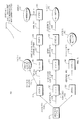
- FIG. 3 is a diagram illustrating an example state machine 300 of a human-to-machine interface (e.g., an interactive voice response (IVR) system).
- the communications management system 105 may be used to analyze the human-to-machine interface to determine states defined therein. For instance, a user may call a credit card company which employs an IVR system. A user may interact with the credit card company's IVR system via voice, dual-tone multi-frequency signaling (DTMF) keypad inputs, or visual representations (as described above) of the states. Each interaction a user has with a state may cause a transition to another state.
- DTMF dual-tone multi-frequency signaling
- An example state machine 300 of an IVR system for a credit card company may initiate interactions with a user during a communication session with a greeting message (state 0) 305.
- state 0 (305) may receive an input for the user including at least one of the following: account number 310a, declaration of a lost/stolen card 310b, or a request to apply for a new card 310c.
- State 0 (305) may then transition to state 1 (315) if an input 310a of an account number is received by the IVR state machine.
- State 1 (315) may then transition to state 7 (330) based on an input 310d requesting an account balance.
- state 1 (315) may transition to state 4 (335) with an input 310c requesting to pay a bill.
- State 4 (335) may accept input values 310h requesting to pay the statement balance, minimum due, or any other amount.
- the state machine 300 transitions to state 5 (350), which requests and receives as input 310k a user's bank account information that is to be used to pay a current bill.
- state machine 300 transitions to state 6 (365) that requests the user to verify the amount the user would like to pay and the bank account information from which to pay the bill.
- state 6 (365) receives the verification information
- state machine 300 transitions to state 8 (370), which issues a confirmation to the user.
- the navigation path of the state machine 300 described above is just one of several navigation paths available for a user as illustrated by state machine 300.
- the states and transitions are inspected by communications management system 105, which may organize the states and associated transitions into decision tree structure, which maps the states of IVR state machine 300 to visual representations of the states. Further, the communications management system 105 may analyze the state machine 300 and associate a goal transaction with each possible navigation path of the state machine 300. This enables a user via the communications management system 105 to reach an end state of every possible navigation path of the state machine via a single interaction with a visual representation of a goal transaction.
- FIG. 4A-B is are network diagram illustrating the construction and presentation of a visual representation of a voice input parameter representing multiple operations of a goal transaction in accordance with an example embodiment of the present invention.
- the first party 409 using a user device 410 having a graphical user interface 412, is in communications with a second party 420 via a human-to-machine interface (e.g., IVR system) 415.
- the IVR system 420 enables the first party 409 to interact with a database of the second party 420.
- the IVR system 415 allows customers 409 to interact with a company's database via a telephone keypad or by speech recognition, after which they can service their own inquiries by following an IVR dialogue.
- the IVR system 415 may respond with a prerecorded or dynamically generated audio to direct users further on how to navigate through states of the IVR system 415.
- the IVR system 415 can be applied to control almost any function where transactions can be sub-divided into a series of simple interactions.
- a communications management system 405 monitors a communications channel 445a for communications with a second party 430 via the IVR system 415. In response to determining that a communications session is being established, the communications management system 405 determines a goal transaction for the communications session as described above. Contemporaneously with determining the goal transaction, the communications management system 405 presents a visual representation of the goal transaction via the graphical user interface 412 of the communication device 410.
- the communications management system 405 determines that the goal transaction for the communications session is a transaction to pay statement balance associated with a credit card.
- the visual representation enables a user to have both visual and tactile interactions 408a-b with the human-to-machine interface 415.
- the communications management system 405 determines provides the amount to pay and account from which to debit funds in order to process the credit card payment.
- the communications management system 405 may determine that the goal transaction of the user is to pay a statement balance, but does not know how much the user would like to pay and from which account to debit funds.
- the communications management system 405 may present the user with a visual representation (or other machine-to-human indicator) having fill-in-the-blank fields for the user to enter the missing information as illustrated in Fig. 4B .
- FIG. 5 is a flow diagram of an example method 500 for facilitating communications for a user transaction that may be executed by the communications management system ( Fig. 1 ).
- the method begins at 505.
- the method 500 determines a goal transaction for a communications session.
- the method 500 constructs and presents a visual representation of a voice input parameter for the goal transaction, where the visual representation represents multiple operations of the goal transaction optionally available for the user to employ to achieve interaction with the human-to-machine interface in fewer stages that through individual interactions with the human-to-machine interface.
- the method 500 enables user interaction with the visual representations.
- the method 500 determines whether the communications session 525 is complete. If the method 500 determines that the session is not complete, method 500 continues at 510. If the method 500 determines that the session is complete, method 500 ends at 530.
- block diagrams and flow diagrams presented herein are merely example representations of embodiments.
- the block diagrams and flow diagrams may include more or fewer blocks or states, have more or fewer interconnections, and the like.
- Other functions known in the art may be employed and are contemplated to be within the scope of the example embodiments presented herein.
- Embodiments or aspects of the invention may be implemented in hardware, firmware, or software. If implemented in software, the software may be implemented in any software language capable of performing the embodiment(s) of the invention.
- the software may be stored on any computer-readable medium, such as RAM, ROM, CD-ROM, and so forth.
- the software includes instructions that can be loaded and executed by a general purpose or application specific processor capable of supporting embodiment(s) of the invention.
Landscapes
- Engineering & Computer Science (AREA)
- Business, Economics & Management (AREA)
- Physics & Mathematics (AREA)
- Theoretical Computer Science (AREA)
- General Physics & Mathematics (AREA)
- General Business, Economics & Management (AREA)
- Strategic Management (AREA)
- Accounting & Taxation (AREA)
- Human Computer Interaction (AREA)
- Computer Networks & Wireless Communication (AREA)
- Signal Processing (AREA)
- Multimedia (AREA)
- Acoustics & Sound (AREA)
- Audiology, Speech & Language Pathology (AREA)
- Health & Medical Sciences (AREA)
- Computational Linguistics (AREA)
- User Interface Of Digital Computer (AREA)
- Financial Or Insurance-Related Operations Such As Payment And Settlement (AREA)
Abstract
Description
- Many human-to-machine interfaces (e.g., interactive voice response (IVR) systems and web browsers) enable users to enter in transactional relationship with customer service providers. For example, users of the human-to-machine interfaces may be able to purchase products/services or pay bills. In some scenarios a transaction requires multiple operations of interaction to be completed.
- The present invention is as claimed in the claims.
- An embodiment of the present invention determines a goal transaction for a user to provide input a to human-to-machine interface. A goal transaction may be an intent transaction of the user with the human-to-machine interface during a communications session. Alternatively, the goal transaction may be an interaction between the user and the interface that the interface is expecting to occur.
- The embodiment may determine the goal transaction by determining all possible navigation paths of a state machine associated with the interface that a user may traverse. In addition, the goal transaction may be determined based on historical statistics based on a history of the user's transactions or other user's transactions with the interface. Also, the goal transaction may be determined based on pending action items requiring user input (e.g., payment of a bill).
- The embodiment constructs and presents a visual representation of a voice input parameter for the goal transaction, where the visual representation of the voice input parameter represents multiple operations of the goal transaction optionally available for the user to employ to achieve interaction with the human-to-machine interface in fewer stages than through individual interactions with the human-to-machine interface. The embodiment further enables the user interaction with the human-to-machine interfaces via the visual representation.
- In addition, the embodiment may track user transactions with the human-to-machine interface and store the user transactions with the human-to-machine interface. Further, the embodiment may determine the goal transaction for the user based on the stored user transactions.
- The embodiment may determine the goal transaction based on a plurality of transactions with the human-to-machine interface of a plurality of users. Also, the embodiment may determine the goal transaction of the user by anticipating the goal transaction based on a current user input to the human-to-machine interface. In addition, the embodiment may determine the goal transaction of the user by determining pending action items requiring user input. For example, the pending action items may include at least one of the following: payment of a bill, address change, and service modification.
- Further, the presented visual representation enables the user to input the input parameter by selecting the visual representation via a touch screen. The visual representation may include fill-in-the-blank field entries to accept additional user input. Also, the visual representations may be presented to the user via a communications interface enabling multi-mode communications with the human-to-machine interface.
- The embodiment may further notify the user that the human-to-machine interface supports input parameters including multiple operations of the goal transaction. Further, the embodiment may analyze the human-to-machine interface to determine states defining available interactions for the user to interact with the human-to-machine interface and determine the goal transaction by accounting for at least a subset of the states.
- It should be understood that embodiments of the present invention can be implemented in the form of a method, system, or computer readable medium with program codes embodied thereon, for facilitating communications for a user transaction. For ease of reading, the term "system" is used in various portions of the description and may represent some or all forms of embodiments and implementations of the present invention, such as systems, methods, apparatuses, devices, computer readable media, network nodes, and networks.
- The foregoing will be apparent from the following more particular description of example embodiments of the invention, as illustrated in the accompanying drawings in which like reference characters refer to the same parts throughout the different views. The drawings are not necessarily to scale, emphasis instead being placed upon illustrating embodiments of the present invention.
-
FIG. 1 is a network diagram illustrating a communications management system for facilitating communications for a user transaction in accordance with an example embodiment of the present invention; -
FIG. 2A is block diagram of a communications management system in accordance with an example embodiment of the present invention; -
FIG. 2B is a block diagram of a communications management system module in accordance with an example embodiment of the present invention; -
FIG. 3 is a diagram illustrating a state machine of a human-to-machine interface in accordance with an example embodiment of the present invention; -
FIGs. 4A-B are network diagrams illustrating the construction and presentation of a visual representation of a voice input parameter representing multiple operations of a goal transaction in accordance with an example embodiment of the present invention; and -
FIG. 5 is a flow diagram of an example method for facilitating communications for a user transaction. - A description of example embodiments of the invention follows.
- Current human-to-machine interfaces enable users to interact with a company's database and enter into a series of transactions (e.g., purchasing products/services and paying bills). Each transaction may require several operations or stages to accept user input or interaction. Some systems enable a user to enter a voice input parameter providing multiple operations of instructions (e.g., single natural language command). However, users of such a system typically do not know what types of commands the system is capable of accepting, at least in the initial period of using a new system. In addition, users may not know that the system is capable of accepting such a single natural language command.
- Embodiments of the present invention improve a user's experience with a new or existing system by assisting the user in learning the capabilities of the human-to-machine interface in a much faster manner than is currently done without the embodiments. Embodiments do so by determining a goal transaction for a user to provide input to human-to-machine interface, then constructing and presenting a visual representation of a voice input parameter for the goal transaction. The visual representations of the voice input parameter can represent multiple operations of the goal transaction optionally available for the user to employ to achieve interaction with the human-to-machine interface in fewer stages than through individual interactions with the human-to-machine interface. In addition, the embodiments enable user interaction with the human-to-machine interfaces via the visual representation.
- It should be noted that voice input may also include speech input. Both voice input and speech input may arise out of an utterance (e.g., spoken input from a user). An utterance may be a single word, entire phrase, sentence, or even several sentences. It should be further noted that voice input and speech input may be used interchangeably herein, and in either case, the broadest meanings are intended.
-
FIG. 1 is a high-level block diagram of acommunications network 100 that may be used within a context of an implementation of the present invention. Thecommunications network 100 includes a collection of communications links interconnecting a plurality of nodes, such ascommunications units 110a-b,access points 125a-b,intermediate nodes 140a-n,communications management system 105, and asecond party 120 via a human-to-machine interface 115 (e.g., an all-interactive voice response (IVR) system), to form an internetwork of nodes. These internetworked nodes communicate by exchanging data packets according to a pre-defined set of network protocols, such as the Transmission Control Protocol/Internet Protocol (TCP/IP) and the Session Initiation Protocol (SIP). A network protocol as used herein is a formal set of rules that define how data is exchanged between nodes in a communications network. - As will be described in more detail below, the
communications management system 105 may be employed to improve, customize, or otherwise modify a user's experience with the human-to-machine interface 115. Before describing thecommunications management system 105 in more detail, a description of thecommunications network 100 is provided. It should be understood that thecommunications management system 105 may be employed in other network topologies or other applications, such as single processor machines. - The
intermediate nodes 140a-n are typically conventional intermediate nodes, such as routers configured to operate within a communications network 101 (e.g., a Voice Over Internet Protocol (VoIP) network). Theaccess points 125a-b contain logic that enable thecommunications units 110a-b to transfer information (e.g., data) via theaccess points machine interface 115 via theintermediate modes 140a-c. To that end, theaccess points 125a-b include circuitry configured to transmit and receive signals (e.g., radio frequency (RF) signals) that carry the information viawireless links access points 125a-b that may be used with the present invention include certain Institute of Electrical and Electronics Engineers (IEEE) 802.11 compliant access points, as well as certain cellular telephone wireless systems that support the transfer of traffic (e.g., data traffic). Other forms of access points now known or hereafter developed are contemplated to be operable with embodiments of the present invention. - The
communications units 110a-b may be conventional communication units, such as laptop computers, desktop computers, wireless transmit/receive units (WTRUs) (e.g., wireless telephones and personal digital assistants (PDAs)), Internet Protocol IP) telephones, and the like, that enable audible and/or visual communications to be converted into signals that are transferred to theaccess points 125a-b via thewireless links access points 125a-b interface thecommunications units 110a-b and human-to-machine interface 115 with thenetwork 100 and enable signals to be transferred among thecommunications units 110a-b, human-to-machine interface 115, and thenetwork 100. Specifically, theaccess points 125a-b convert signals, received from thecommunications units 110a-b and human-to-machine interface 115 via the wireless links, 111a, 111b into data packets (not shown) that are transferred onto thenetwork 100, as well as convert packets received from the network into signals that are transferred to thecommunications units 110a-b and human-to-machine interface 115. Information (e.g., data, voice, or video) is typically conveyed between thecommunications units 110a-b and human-to-machine interface 115. It should be noted that embodiments of the present invention may be adapted to work with fixed as well as mobile devices that are able to communicate via a communications network. These fixed devices may include telephone units, personal computers, and the like that are wired to a network. - The human-to-
machine interface 115 may employ a telephony interface (not shown) which allows users of thecommunications units 110a-b to interact with a database (not shown) (e.g., a customer service provider database) to acquire information from or enter data into the database via a telephone keypad or by speech recognition. For example, banks and credit card companies use IVR systems so that their customers can receive up-to-date account information instantly and easily without having to speak directly to a person. - As illustrated, a
communications management system 105 may be located at an intermediate point of thecommunications network 100 betweencommunication units 110a-b and human-to-machine interface 115. Optionally, thecommunications management system 105 may be logically or physically coupled to thecommunications units 110a-b or human-to-machine interface 115. Thecommunications management system 105 may acquire knowledge of the existence of the human-to-machine interface 115 by active searching or passive learning. - For example, the
communications management system 105 may search for human-to-machine interfaces actively by issuing discovery messages through thecommunications network 101 that elicit a specific response unique to a specific type of human-to-machine interface (e.g., IVR system). Alternatively, thecommunications management system 105 may passively learn about human-to-machine interfaces by monitoring communications messages over thecommunications network 101 to determine whether a communications session is being established with the human-to-machine interface 115, thereby enabling thecommunications management system 105 to discover the human-to-machine interface 115. In another embodiment, the human-to-machine interface 115 may be discovered by thecommunications management system 105 via a notification message fromcommunications units 110a-b, human-to-machine interface 115, or a 3rd party (not shown). - The
communications management system 105 may then inspect the discovered human-to-machine interface 115 to determine states defined therein. Each state of the human-to-machine interface 115 may represent choices available to a user to navigate the human-to-machine interface. For each state of the human-to-machine interface 115, thecommunications management system 105 may compose visual representations (not shown) of the states of the human-to-machine interface 115 to display to the user. - In addition or alternatively, the
communications management system 105 enables user interaction with the human-to-machine interface 115 via the visual representations by displaying the visual representations on a graphical user interface of thecommunications units 110a-b and triggering a change of state of the human-to-machine interface 115 upon user interaction with a visual representation. User interaction with the visual representation may include touching a visual representation (note shown) via a touch screen, clicking a visual representation via a cursor, or selecting a visual representation via a voice command. Thecommunications management system 105 may trigger a change of state in the human-to-machine interface 115 by issuing a generated voice command to the human-to-machine interface 115 or a dual-tone multi-frequency signaling (DTMF) keypad input, thereby replacing any additional action required by the user save the user's interaction with the visual representations. - As stated above, some transactions with the human-to-
machine interface 115 may include many stages or operations. In order to facilitate and expedite a communications session, thecommunications management system 105 determines a goal transaction for a user to provide input to a human-to-machine interface. For example, a goal transaction may be a request to purchase a product/service or pay a bill. Further, thecommunications management system 105 constructs and presents a visual representation of the voice input parameter for the goal transaction. For instance, the visual representation of the voice input parameter may represent multiple operations of the goal transaction optionally available for the user to employ to achieve interaction with the human-to-machine interface 115 in fewer stages than through individual interaction the human-to-machine interface 115. In addition, in some embodiments, thecommunications management system 105 enables user interaction with the human-to-machine interface via the visual representations. For instance, a user interaction with the visual representation may include touching the visual representation via a touch screen, clicking the visual representation via a cursor, or selecting the visual representation via a voice command (e.g., utterance). - In order to determine the goal transaction for a user, the
communications management system 105 may track user transactions with the human-to-machine interface. For instance, thecommunications management system 105, upon determining that a communications session with the human-to-machine interface 115 has begun or is about to begin, monitors changes of state of the human-to-machine interface 150 during the communications session. Further, thecommunications management system 105 determines an end state of the transaction associated with the communications session and stores the user transactions (e.g., transition states) leading to the end state. - For example, a user may begin a communications session with the credit card company in order to pay a bill. During the communications session, the user may be required to enter several pieces of information (e.g., credit card number, security code, and payment amount), where an entry of a piece of information may cause the human-to-
machine interface 115 transition to a different state. Based on the end state in the transition states required to reach the end state, thecommunications management system 105 may determine a goal transaction and an associated visual representation of a voice input parameter for the goal transaction. Once the visual representation is constructed, thecommunications management system 105 enables the user to complete a goal transaction by simply selecting the visual representation. - The
communications management system 105 may also determine goal transactions based on a plurality of transactions with the human-to-machine interface 115 of a plurality of users. For example, thecommunications management system 105 may present visual representations associated with the top ten determine goal transactions of the plurality of users. In this way, thecommunications management system 105 may predict a goal transaction for a user beginning a communications session with the human-to-machine interface 115. - In addition or alternatively, the
communications management system 105 may determine the goal transaction of a user by anticipating the goal transaction based on a current user input to the human-to-machine interface 115. Thecommunications management system 105 may be able to make such a determination via a decision tree structure associated with a state machine of the human-to-machine interface 115. - For example, the human-to-
machine interface 115 may have an associated state machine that enables the interface to transition from one state to another upon consuming user input. For instance, a beginning state of the human-to-machine interface 115 may enable a user to transition to several different states of the state machine, where each state is associated with a different navigation path. For example, a beginning state of a state machine associated with a credit card company may allow a user to transition to navigation paths associated with, for example, i) accessing account balance information, ii) payment of a bill, and iii) open a new account. Thus, once the user transition to a navigation path associated with the payment of a bill, thecommunications management system 105 may present visual representations of a goal transaction to pay a pending account balance. - Further, the
communications management system 105 may determine a goal transaction of the user by determining pending action items requiring user input. For example, once a user begins a communications session with the human-to-machine interface 115, thecommunications management system 105 may receive information associated with pending action items. Pending action items may include, for example, payment of a bill, address change, and service modification. - The
communications management system 105 may determine the pending action items via active or passive discovery communications messages. For instance, thecommunications management system 105 may issue a discovery request message to the human-to-machine interface 115 requesting information associated with any pending action items. Upon receiving such information, thecommunication management system 115 may determine that the pending action items may be possible goal transactions associated with a current communications session of the user with the human-to-machine interface 115 and construct and present visual representations associated with the pending action items. Also, thecommunications management system 105 may receive such information from the user or human-to-machine interface 115 without issuing a discovery request message. - In another example embodiment, the
communications management system 105 may determine goal transactions of the user by analyzing the human-to-machine interface 115. For example, thecommunications management system 105 may analyze the human-to-machine interface 115 to determine states (e.g., of a state machine associated with the interface as described above) defining available interactions for the user to interact with the human-to-machine interface 115. Using at least a subset of the states, the communications management system 104 may determine goal transactions for the user. - In addition, the
communications management system 105 may notify the user that the human-to-machine interface supports input parameters including multiple operations of the user's goal transaction. This enables users without prior knowledge of the human-to-machine interface's capabilities to be informed of the capabilities of the human-to-machine interface 115 at the outset of a communications session. In addition, thecommunications management system 105 may present the user with example input parameters (that may be associated with determined goal transactions) such that the user is able to model an input parameter of the user's goal transaction with the provided examples. -
FIG. 2A is block diagram of acommunications management system 205 that may be used in connection with an embodiment of the present invention. Thecommunications management system 205 includes amemory 220 coupled to aprocessor 225 via amemory bus 222, and astorage device 235 and anetwork interface 230 coupled to theprocessor 225 via an input/output (I/O)bus 234. It should be noted thatcommunications management system 205 may include other devices, such as keyboards, display units and the like. Thenetwork interface 230 interfaces thecommunications management system 205 with the network 101 (seeFIG. 1 ) and enables data (e.g., packets to be transferred between the human-to-machine interface 115 (seeFig. 1 ) and other nodes, such ascommunications units 110a-b and the second party 120) in thenetwork 101. To that end, thenetwork interface 230 may include conventional circuitry that incorporates signal, electrical and mechanical characteristics, and interchange circuits to interface with the physical media of thenetwork 100 and protocols running over that media. Thestorage device 235 is a conventional storage device (e.g., a disk) capable of storing, inter alia, states of human-to-machine interface, decision tree structures of the states, goal transactions, visual representations of the states, and visual representations of the goal transactions. - The
memory 220 is an example of a computer-readable medium, optionally implemented as a RAM employing RAM devices, such as DRAM devices and/or flash memory devices. Thememory 220 contains various software and data structures used by theprocessor 225, such as software and data structures that implement aspects of the present invention. Specifically, thememory 220 may store software configured to serve as anoperating system 215 or provide communications management services viacommunications management module 210. Theoperating system 215 can be used to functionally organizes thecommunications management system 205 by invoking operations in support of software processes and services executing on thecommunications management system 205, such as communications management services. Thecommunications management services 210, as will be described below, may include non-transitory computer-executable instructions to facilitate communications for a user transaction by determining goal transactions for a user, constructing and presenting visual representations of the goal transactions, and enabling user interaction with the human-to-machine interface via the visual representations. - The
storage device 235 may include aninformation database 240, which may be implemented in the form of a data structure that is configured to hold various information used to facilitate communications for a user transaction, such as states of a human-to-machine interface, decision tree structures of the states, goal transactions, visual representations of the states, and visual representations of the goal transactions. -
FIG. 2B is a block diagram of an example embodiment of acommunications services module 210 that includes a determiningmodule 250, constructingmodule 255,tracking module 260, and notifyingmodule 265. - The determining
module 250 determines goal transactions for a user transaction associated with a communications session with the human-to-machine interface 115. In addition, the determiningmodule 250 analyzes the human-to-machine interface 115 and determined states defined therein. In response to determining the goal transactions and the states of the human-to-machine interface, the determiningmodule 250 informs theconstructing module 255 of the determined goal transactions and determined states of the human-to-machine interface 115. - Based on the determined goal transactions and the states of the human-to-machine interface, the
constructing module 255 constructs and presents visual representations of the goal transactions to the user. In addition, theconstructing module 255 enables user interaction with the human-to-machine interface 115. For example, theconstructing module 255 enables a user to directly transition to an end-state of the human-to-machine interface 115 associated with the goal transaction by interacting with the visual representation associated with the goal transaction. For instance, the constructing module may encode the visual representations with input parameters associated with each state of a navigation path associated with the goal transactions. Thus, upon the user's interaction with the visual representation associated with the user's goal transaction, the state machine of the human-to-machine interface transitions through the states provided by the visual representations via the communications management system. - Further, the
tracking module 260 may track a history transactions between a user and the human-to-machine interface and/or transactions between a plurality of users and the human-to-machine interface. The tracking module may store the history of transactions and pass the historical data to the determiningmodule 250, which may then determine possible goal transactions using the historical data. - In addition, the notifying
module 265 may provide users with an indication that the human-to-machine interface is capable of accepting a single input parameter representing multiple operations of a user transaction with the human-to-machine interface. Further, the notifyingmodule 265 may provide the user with example input parameters including multiple operations of a user transaction, such that the user may model an input parameter from the provided example. -
FIG. 3 is a diagram illustrating anexample state machine 300 of a human-to-machine interface (e.g., an interactive voice response (IVR) system). As described above, thecommunications management system 105 may be used to analyze the human-to-machine interface to determine states defined therein. For instance, a user may call a credit card company which employs an IVR system. A user may interact with the credit card company's IVR system via voice, dual-tone multi-frequency signaling (DTMF) keypad inputs, or visual representations (as described above) of the states. Each interaction a user has with a state may cause a transition to another state. - An
example state machine 300 of an IVR system for a credit card company may initiate interactions with a user during a communication session with a greeting message (state 0) 305. In this example, state 0 (305) may receive an input for the user including at least one of the following:account number 310a, declaration of a lost/stolencard 310b, or a request to apply for a new card 310c. State 0 (305) may then transition to state 1 (315) if aninput 310a of an account number is received by the IVR state machine. State 1 (315) may then transition to state 7 (330) based on aninput 310d requesting an account balance. Alternatively, state 1 (315) may transition to state 4 (335) with an input 310c requesting to pay a bill. State 4 (335) may acceptinput values 310h requesting to pay the statement balance, minimum due, or any other amount. Once the amount to be paid is received by state 4 (335), thestate machine 300 transitions to state 5 (350), which requests and receives asinput 310k a user's bank account information that is to be used to pay a current bill. Once state 5 (350) receivesinput 310k,state machine 300 transitions to state 6 (365) that requests the user to verify the amount the user would like to pay and the bank account information from which to pay the bill. Once state 6 (365) receives the verification information, thestate machine 300 transitions to state 8 (370), which issues a confirmation to the user. The navigation path of thestate machine 300 described above is just one of several navigation paths available for a user as illustrated bystate machine 300. - The states and transitions are inspected by
communications management system 105, which may organize the states and associated transitions into decision tree structure, which maps the states ofIVR state machine 300 to visual representations of the states. Further, thecommunications management system 105 may analyze thestate machine 300 and associate a goal transaction with each possible navigation path of thestate machine 300. This enables a user via thecommunications management system 105 to reach an end state of every possible navigation path of the state machine via a single interaction with a visual representation of a goal transaction. -
FIG. 4A-B is are network diagram illustrating the construction and presentation of a visual representation of a voice input parameter representing multiple operations of a goal transaction in accordance with an example embodiment of the present invention. - The
first party 409, using auser device 410 having agraphical user interface 412, is in communications with asecond party 420 via a human-to-machine interface (e.g., IVR system) 415. TheIVR system 420 enables thefirst party 409 to interact with a database of thesecond party 420. - For example, in telecommunications, the
IVR system 415 allowscustomers 409 to interact with a company's database via a telephone keypad or by speech recognition, after which they can service their own inquiries by following an IVR dialogue. In addition, theIVR system 415 may respond with a prerecorded or dynamically generated audio to direct users further on how to navigate through states of theIVR system 415. TheIVR system 415 can be applied to control almost any function where transactions can be sub-divided into a series of simple interactions. - In this example, a
communications management system 405 monitors acommunications channel 445a for communications with a second party 430 via theIVR system 415. In response to determining that a communications session is being established, thecommunications management system 405 determines a goal transaction for the communications session as described above. Contemporaneously with determining the goal transaction, thecommunications management system 405 presents a visual representation of the goal transaction via thegraphical user interface 412 of thecommunication device 410. - For instance, in this example, the
communications management system 405 determines that the goal transaction for the communications session is a transaction to pay statement balance associated with a credit card. The visual representation enables a user to have both visual andtactile interactions 408a-b with the human-to-machine interface 415. In example depicted inFig. 4A , thecommunications management system 405 determines provides the amount to pay and account from which to debit funds in order to process the credit card payment. In certain scenarios, thecommunications management system 405 may determine that the goal transaction of the user is to pay a statement balance, but does not know how much the user would like to pay and from which account to debit funds. In such a scenario, thecommunications management system 405 may present the user with a visual representation (or other machine-to-human indicator) having fill-in-the-blank fields for the user to enter the missing information as illustrated inFig. 4B . -
FIG. 5 is a flow diagram of anexample method 500 for facilitating communications for a user transaction that may be executed by the communications management system (Fig. 1 ). The method begins at 505. At 510, themethod 500 determines a goal transaction for a communications session. At 515, themethod 500 constructs and presents a visual representation of a voice input parameter for the goal transaction, where the visual representation represents multiple operations of the goal transaction optionally available for the user to employ to achieve interaction with the human-to-machine interface in fewer stages that through individual interactions with the human-to-machine interface. At 520, themethod 500 enables user interaction with the visual representations. Subsequently, themethod 500 determines whether thecommunications session 525 is complete. If themethod 500 determines that the session is not complete,method 500 continues at 510. If themethod 500 determines that the session is complete,method 500 ends at 530. - It should be understood that the block diagrams and flow diagrams presented herein are merely example representations of embodiments. The block diagrams and flow diagrams may include more or fewer blocks or states, have more or fewer interconnections, and the like. Other functions known in the art may be employed and are contemplated to be within the scope of the example embodiments presented herein.
- Embodiments or aspects of the invention may be implemented in hardware, firmware, or software. If implemented in software, the software may be implemented in any software language capable of performing the embodiment(s) of the invention. The software may be stored on any computer-readable medium, such as RAM, ROM, CD-ROM, and so forth. The software includes instructions that can be loaded and executed by a general purpose or application specific processor capable of supporting embodiment(s) of the invention.
- While this invention has been particularly shown and described with references to example embodiments thereof, it will be understood by those skilled in the art that various changes in form and details may be made therein without departing from the scope of the invention encompassed by the appended claims.
Claims (17)
- A method for facilitating communications for a user transaction, the method comprising:determining a goal transaction for a user to provide input to a human-to-machine interface;constructing and presenting a visual representation of a voice input parameter for the goal transaction, the visual representation of the voice input parameter representing multiple operations of the goal transaction optionally available for the user to employ to achieve interaction with the human-to-machine interface in fewer stages than through individual interactions with the human-to-machine interface; andenabling a user interaction with the human-to-machine interface via the visual representation.
- The method of claim 1 further comprising:tracking user transactions with the human-to-machine interface;storing the user transactions with the human-to-machine interface; anddetermining the goal transaction for the user based on the stored user transactions.
- The method of claim 1 wherein determining the goal transaction includes determining the goal transaction based on a plurality of transactions with the human-to-machine interface of a plurality of users.
- The method of claim 1 wherein determining the goal transaction of the user includes either anticipating the goal transaction based on a current user input to the human-to-machine interface or determining the goal transaction of the user includes determining pending action items requiring user input, and in which later case, optionally, wherein the pending action items include at least one of the following:payment of a bill, address change, and service modification.
- The method of claim 1 wherein the visual representation enables the user to input the input parameter by selecting the visual representation via a touch screen and, optionally, wherein the visual representation includes fill in the blank field entries requiring additional user input.
- The method of claim 1 wherein the visual representations are presented to the user via a communications interface enabling multi-mode communication with the human-to-machine interface.
- The method of claim 1 further comprising notifying the user that the human-to-machine interface supports input parameters including multiple operations of the goal transaction.
- The method of claim 1 further comprising:analyzing the human-to-machine interface to determine states defining available interactions for the user to interact with the human-to-machine interface; andwherein determining the goal transaction includes accounting for at least a subset of the states.
- A system for facilitating communications for a user transaction, the system comprising:a determining module configured to determine a goal transaction for a user to provide input to a human-to-machine interface;a constructing module configured to construct and present a visual representation of a voice input parameter for the goal transaction, the visual representation of the voice input parameter representing multiple operations of the goal transaction optionally available for the user to employ to achieve interaction with the human-to-machine interface in fewer stages than through individual interactions with the human-to-machine interface; andwherein the visual representations enable user interaction with the human-to-machine interface.
- The system of claim 9 further comprising:a tracking module configured to track user transactions with the human-to-machine interface;a data store configured to store the user transactions with the human-to-machine interface; andthe determining module further configured to determine the goal transaction for the user based on the stored user transactions.
- The system of claim 9 wherein the determining module is further configured to either:a) determine the goal transaction based on a plurality of transactions with the human-to-machine interface of a plurality of users; orb) anticipate the goal transaction based on a current user input to the human-to-machine interface; orc) determine pending action items requiring user input, the pending action items being identified as possible goal transactions of the user, and in which last case, optionally, the pending action items include at least one of the following: payment of a bill, address change, and service modification.
- The system of claim 9 wherein the visual representation enables the user to input the input parameter by selecting the visual representation via a touch screen.
- The system of claim 12 wherein the visual representation includes fill in the blank field entries requiring additional user input.
- The system of claim 9 further comprising a communications interface configured to present the visual representation to the user, the communications interface enabling multi-mode communications with the human-to-machine interface.
- The system of claim 9 further comprising a notifying module configured to notify the user that the human-to-machine interface provider supports input parameters including multiple operations of the goal transaction.
- The system of claim 9 wherein the determining module is further configured to:analyze the human-to-machine interface to determine states defining available interactions for the user to interact with the human-to-machine interface; anddetermine the goal transaction by accounting for at least a subset of the states.
- A computer readable medium having computer readable program codes embodied therein for facilitating communications for a user transaction, the computer readable program codes including instructions that, when executed by a processor, cause the processor to carry out the method of any one of claims 1 to 8.
Applications Claiming Priority (1)
| Application Number | Priority Date | Filing Date | Title |
|---|---|---|---|
| US13/452,347 US9037472B2 (en) | 2012-04-20 | 2012-04-20 | Method and system for facilitating communications for a user transaction |
Publications (3)
| Publication Number | Publication Date |
|---|---|
| EP2654280A2 true EP2654280A2 (en) | 2013-10-23 |
| EP2654280A3 EP2654280A3 (en) | 2015-10-21 |
| EP2654280B1 EP2654280B1 (en) | 2017-07-05 |
Family
ID=48087452
Family Applications (1)
| Application Number | Title | Priority Date | Filing Date |
|---|---|---|---|
| EP13163510.4A Not-in-force EP2654280B1 (en) | 2012-04-20 | 2013-04-12 | Method and system for facilitating communications for a user transaction |
Country Status (3)
| Country | Link |
|---|---|
| US (1) | US9037472B2 (en) |
| EP (1) | EP2654280B1 (en) |
| CN (1) | CN103376992B (en) |
Families Citing this family (9)
| Publication number | Priority date | Publication date | Assignee | Title |
|---|---|---|---|---|
| EP2283156B1 (en) | 2008-05-02 | 2015-11-11 | Interleukin Genetics, Inc. | Detecting genetic predisposition to osteoarthritis associated conditions |
| US11094320B1 (en) * | 2014-12-22 | 2021-08-17 | Amazon Technologies, Inc. | Dialog visualization |
| CN104574063A (en) * | 2015-01-26 | 2015-04-29 | 深圳前海万融智能信息有限公司 | Natural language mobile payment method and device based on customization |
| US10236017B1 (en) * | 2015-09-29 | 2019-03-19 | Amazon Technologies, Inc. | Goal segmentation in speech dialogs |
| US10127926B2 (en) * | 2016-06-10 | 2018-11-13 | Google Llc | Securely executing voice actions with speaker identification and authentication input types |
| US11726979B2 (en) * | 2016-09-13 | 2023-08-15 | Oracle International Corporation | Determining a chronological order of transactions executed in relation to an object stored in a storage system |
| US12118522B2 (en) * | 2019-08-22 | 2024-10-15 | Paymentus Corporation | Systems and methods for interactive video presentation of transactional information |
| US12106760B2 (en) * | 2020-10-22 | 2024-10-01 | Capital One Services, Llc | Systems and methods using natural language processing to identify irregularities in a user utterance |
| CN114792233A (en) * | 2021-01-25 | 2022-07-26 | 腾讯科技(深圳)有限公司 | Data processing method and device, computer equipment and readable storage medium |
Family Cites Families (20)
| Publication number | Priority date | Publication date | Assignee | Title |
|---|---|---|---|---|
| US7065188B1 (en) * | 1999-10-19 | 2006-06-20 | International Business Machines Corporation | System and method for personalizing dialogue menu for an interactive voice response system |
| US7668718B2 (en) * | 2001-07-17 | 2010-02-23 | Custom Speech Usa, Inc. | Synchronized pattern recognition source data processed by manual or automatic means for creation of shared speaker-dependent speech user profile |
| US7421389B2 (en) * | 2002-11-13 | 2008-09-02 | At&T Knowledge Ventures, L.P. | System and method for remote speech recognition |
| US7215743B2 (en) * | 2002-12-20 | 2007-05-08 | International Business Machines Corporation | Telephony signals containing an IVR decision tree |
| US7263483B2 (en) * | 2003-04-28 | 2007-08-28 | Dictaphone Corporation | USB dictation device |
| US8340971B1 (en) * | 2005-01-05 | 2012-12-25 | At&T Intellectual Property Ii, L.P. | System and method of dialog trajectory analysis |
| US7813485B2 (en) * | 2005-05-26 | 2010-10-12 | International Business Machines Corporation | System and method for seamlessly integrating an interactive visual menu with an voice menu provided in an interactive voice response system |
| US20070106515A1 (en) * | 2005-11-09 | 2007-05-10 | Sbc Knowledge Ventures, L.P. | Automated interactive statistical call visualization using abstractions stack model framework |
| US20070143114A1 (en) * | 2005-12-21 | 2007-06-21 | International Business Machines Corporation | Business application dialogues architecture and toolset |
| US7835911B2 (en) * | 2005-12-30 | 2010-11-16 | Nuance Communications, Inc. | Method and system for automatically building natural language understanding models |
| US20080140413A1 (en) * | 2006-12-07 | 2008-06-12 | Jonathan Travis Millman | Synchronization of audio to reading |
| US8265234B2 (en) * | 2007-03-16 | 2012-09-11 | Intellicomm Inc. | Systems and methods for enabling a user to more easily navigate an interactive voice response (IVR) menu |
| US20090287514A1 (en) * | 2007-03-16 | 2009-11-19 | Alliance Of Professionals & Consultants, Inc. | Rapid candidate opt-in confirmation system |
| US8260619B1 (en) * | 2008-08-22 | 2012-09-04 | Convergys Cmg Utah, Inc. | Method and system for creating natural language understanding grammars |
| US8370160B2 (en) * | 2007-12-31 | 2013-02-05 | Motorola Mobility Llc | Methods and apparatus for implementing distributed multi-modal applications |
| US20090209239A1 (en) * | 2008-02-18 | 2009-08-20 | Movidilo S.L. | Self-service application platform for wireless devices |
| US8934618B2 (en) * | 2008-12-29 | 2015-01-13 | Avaya Inc. | Method for analysing an interactive voice response system |
| US8705706B2 (en) * | 2010-03-22 | 2014-04-22 | Avaya Inc. | Interactive flowgraph for analyzing caller utterances |
| US8914293B2 (en) * | 2010-08-25 | 2014-12-16 | Unwired Planet, Llc | Web browser implementation of interactive voice response instructions |
| US8831208B2 (en) * | 2011-09-23 | 2014-09-09 | Synchronoss Technologies, Inc. | System and method for optimizing call flows of a spoken dialog system |
-
2012
- 2012-04-20 US US13/452,347 patent/US9037472B2/en active Active
-
2013
- 2013-04-12 EP EP13163510.4A patent/EP2654280B1/en not_active Not-in-force
- 2013-04-19 CN CN201310138618.XA patent/CN103376992B/en not_active Expired - Fee Related
Non-Patent Citations (1)
| Title |
|---|
| None |
Also Published As
| Publication number | Publication date |
|---|---|
| EP2654280A3 (en) | 2015-10-21 |
| US9037472B2 (en) | 2015-05-19 |
| CN103376992B (en) | 2016-08-17 |
| EP2654280B1 (en) | 2017-07-05 |
| CN103376992A (en) | 2013-10-30 |
| US20130282380A1 (en) | 2013-10-24 |
Similar Documents
| Publication | Publication Date | Title |
|---|---|---|
| EP2654280B1 (en) | Method and system for facilitating communications for a user transaction | |
| US9542074B2 (en) | Method and apparatus for enhancing an interactive voice response (IVR) system | |
| CN113647067B (en) | Maintaining machine language model state across communication channels | |
| AU2012238229B2 (en) | Multi-modal customer care system | |
| US12452197B2 (en) | System and method for proactive intervention to reduce high cost channel usage | |
| US20200236071A1 (en) | Automated population of deep-linked interfaces during programmatically established chatbot sessions | |
| US9270811B1 (en) | Visual options for audio menu | |
| US10847136B2 (en) | System and method for mapping a customer journey to a category | |
| CN112929499B (en) | Dialogue interaction method and device, computer equipment and computer-readable storage medium | |
| US11153236B2 (en) | Real-time integration of machine intelligence into client messaging platforms | |
| US11948557B2 (en) | Methods and apparatus for leveraging sentiment values in flagging and/or removal of real time workflows | |
| KR102821062B1 (en) | Systems and techniques for handling long texts with pre-trained language models | |
| US11967309B2 (en) | Methods and apparatus for leveraging machine learning for generating responses in an interactive response system | |
| US11922928B2 (en) | Multi-tier rule and AI processing for high-speed conversation scoring | |
| CN115567646A (en) | Intelligent outgoing call method, device, computer equipment and storage medium | |
| US12301757B2 (en) | Methods, apparatuses, and systems for dynamically navigating interactive communication systems | |
| CN111507698A (en) | Processing method and device for transferring accounts, computing equipment and medium | |
| US8594281B2 (en) | Dynamic menu framework | |
| CN115309883A (en) | Intelligent response method and device, electronic equipment and medium | |
| US20250315641A1 (en) | Systems and methods for automatically creating and training virtual assistants |
Legal Events
| Date | Code | Title | Description |
|---|---|---|---|
| PUAI | Public reference made under article 153(3) epc to a published international application that has entered the european phase |
Free format text: ORIGINAL CODE: 0009012 |
|
| AK | Designated contracting states |
Kind code of ref document: A2 Designated state(s): AL AT BE BG CH CY CZ DE DK EE ES FI FR GB GR HR HU IE IS IT LI LT LU LV MC MK MT NL NO PL PT RO RS SE SI SK SM TR |
|
| AX | Request for extension of the european patent |
Extension state: BA ME |
|
| PUAL | Search report despatched |
Free format text: ORIGINAL CODE: 0009013 |
|
| AK | Designated contracting states |
Kind code of ref document: A3 Designated state(s): AL AT BE BG CH CY CZ DE DK EE ES FI FR GB GR HR HU IE IS IT LI LT LU LV MC MK MT NL NO PL PT RO RS SE SI SK SM TR |
|
| AX | Request for extension of the european patent |
Extension state: BA ME |
|
| RIC1 | Information provided on ipc code assigned before grant |
Ipc: G06Q 20/30 20120101ALI20150916BHEP Ipc: G10L 15/28 20130101ALI20150916BHEP Ipc: H04M 3/493 20060101AFI20150916BHEP Ipc: G06Q 20/32 20120101ALI20150916BHEP Ipc: G10L 15/22 20060101ALI20150916BHEP |
|
| 17P | Request for examination filed |
Effective date: 20160415 |
|
| RBV | Designated contracting states (corrected) |
Designated state(s): AL AT BE BG CH CY CZ DE DK EE ES FI FR GB GR HR HU IE IS IT LI LT LU LV MC MK MT NL NO PL PT RO RS SE SI SK SM TR |
|
| 17Q | First examination report despatched |
Effective date: 20160810 |
|
| GRAP | Despatch of communication of intention to grant a patent |
Free format text: ORIGINAL CODE: EPIDOSNIGR1 |
|
| INTG | Intention to grant announced |
Effective date: 20170125 |
|
| GRAS | Grant fee paid |
Free format text: ORIGINAL CODE: EPIDOSNIGR3 |
|
| GRAA | (expected) grant |
Free format text: ORIGINAL CODE: 0009210 |
|
| AK | Designated contracting states |
Kind code of ref document: B1 Designated state(s): AL AT BE BG CH CY CZ DE DK EE ES FI FR GB GR HR HU IE IS IT LI LT LU LV MC MK MT NL NO PL PT RO RS SE SI SK SM TR |
|
| REG | Reference to a national code |
Ref country code: GB Ref legal event code: FG4D |
|
| REG | Reference to a national code |
Ref country code: CH Ref legal event code: EP |
|
| REG | Reference to a national code |
Ref country code: AT Ref legal event code: REF Ref document number: 907340 Country of ref document: AT Kind code of ref document: T Effective date: 20170715 |
|
| REG | Reference to a national code |
Ref country code: IE Ref legal event code: FG4D |
|
| REG | Reference to a national code |
Ref country code: DE Ref legal event code: R096 Ref document number: 602013023041 Country of ref document: DE |
|
| REG | Reference to a national code |
Ref country code: NL Ref legal event code: MP Effective date: 20170705 |
|
| REG | Reference to a national code |
Ref country code: AT Ref legal event code: MK05 Ref document number: 907340 Country of ref document: AT Kind code of ref document: T Effective date: 20170705 |
|
| REG | Reference to a national code |
Ref country code: LT Ref legal event code: MG4D |
|
| PG25 | Lapsed in a contracting state [announced via postgrant information from national office to epo] |
Ref country code: HR Free format text: LAPSE BECAUSE OF FAILURE TO SUBMIT A TRANSLATION OF THE DESCRIPTION OR TO PAY THE FEE WITHIN THE PRESCRIBED TIME-LIMIT Effective date: 20170705 Ref country code: FI Free format text: LAPSE BECAUSE OF FAILURE TO SUBMIT A TRANSLATION OF THE DESCRIPTION OR TO PAY THE FEE WITHIN THE PRESCRIBED TIME-LIMIT Effective date: 20170705 Ref country code: AT Free format text: LAPSE BECAUSE OF FAILURE TO SUBMIT A TRANSLATION OF THE DESCRIPTION OR TO PAY THE FEE WITHIN THE PRESCRIBED TIME-LIMIT Effective date: 20170705 Ref country code: NL Free format text: LAPSE BECAUSE OF FAILURE TO SUBMIT A TRANSLATION OF THE DESCRIPTION OR TO PAY THE FEE WITHIN THE PRESCRIBED TIME-LIMIT Effective date: 20170705 Ref country code: LT Free format text: LAPSE BECAUSE OF FAILURE TO SUBMIT A TRANSLATION OF THE DESCRIPTION OR TO PAY THE FEE WITHIN THE PRESCRIBED TIME-LIMIT Effective date: 20170705 Ref country code: SE Free format text: LAPSE BECAUSE OF FAILURE TO SUBMIT A TRANSLATION OF THE DESCRIPTION OR TO PAY THE FEE WITHIN THE PRESCRIBED TIME-LIMIT Effective date: 20170705 Ref country code: NO Free format text: LAPSE BECAUSE OF FAILURE TO SUBMIT A TRANSLATION OF THE DESCRIPTION OR TO PAY THE FEE WITHIN THE PRESCRIBED TIME-LIMIT Effective date: 20171005 |
|
| PG25 | Lapsed in a contracting state [announced via postgrant information from national office to epo] |
Ref country code: PL Free format text: LAPSE BECAUSE OF FAILURE TO SUBMIT A TRANSLATION OF THE DESCRIPTION OR TO PAY THE FEE WITHIN THE PRESCRIBED TIME-LIMIT Effective date: 20170705 Ref country code: LV Free format text: LAPSE BECAUSE OF FAILURE TO SUBMIT A TRANSLATION OF THE DESCRIPTION OR TO PAY THE FEE WITHIN THE PRESCRIBED TIME-LIMIT Effective date: 20170705 Ref country code: IS Free format text: LAPSE BECAUSE OF FAILURE TO SUBMIT A TRANSLATION OF THE DESCRIPTION OR TO PAY THE FEE WITHIN THE PRESCRIBED TIME-LIMIT Effective date: 20171105 Ref country code: ES Free format text: LAPSE BECAUSE OF FAILURE TO SUBMIT A TRANSLATION OF THE DESCRIPTION OR TO PAY THE FEE WITHIN THE PRESCRIBED TIME-LIMIT Effective date: 20170705 Ref country code: GR Free format text: LAPSE BECAUSE OF FAILURE TO SUBMIT A TRANSLATION OF THE DESCRIPTION OR TO PAY THE FEE WITHIN THE PRESCRIBED TIME-LIMIT Effective date: 20171006 Ref country code: BG Free format text: LAPSE BECAUSE OF FAILURE TO SUBMIT A TRANSLATION OF THE DESCRIPTION OR TO PAY THE FEE WITHIN THE PRESCRIBED TIME-LIMIT Effective date: 20171005 Ref country code: RS Free format text: LAPSE BECAUSE OF FAILURE TO SUBMIT A TRANSLATION OF THE DESCRIPTION OR TO PAY THE FEE WITHIN THE PRESCRIBED TIME-LIMIT Effective date: 20170705 |
|
| REG | Reference to a national code |
Ref country code: DE Ref legal event code: R097 Ref document number: 602013023041 Country of ref document: DE |
|
| PG25 | Lapsed in a contracting state [announced via postgrant information from national office to epo] |
Ref country code: RO Free format text: LAPSE BECAUSE OF FAILURE TO SUBMIT A TRANSLATION OF THE DESCRIPTION OR TO PAY THE FEE WITHIN THE PRESCRIBED TIME-LIMIT Effective date: 20170705 Ref country code: CZ Free format text: LAPSE BECAUSE OF FAILURE TO SUBMIT A TRANSLATION OF THE DESCRIPTION OR TO PAY THE FEE WITHIN THE PRESCRIBED TIME-LIMIT Effective date: 20170705 Ref country code: DK Free format text: LAPSE BECAUSE OF FAILURE TO SUBMIT A TRANSLATION OF THE DESCRIPTION OR TO PAY THE FEE WITHIN THE PRESCRIBED TIME-LIMIT Effective date: 20170705 |
|
| PLBE | No opposition filed within time limit |
Free format text: ORIGINAL CODE: 0009261 |
|
| STAA | Information on the status of an ep patent application or granted ep patent |
Free format text: STATUS: NO OPPOSITION FILED WITHIN TIME LIMIT |
|
| PG25 | Lapsed in a contracting state [announced via postgrant information from national office to epo] |
Ref country code: SM Free format text: LAPSE BECAUSE OF FAILURE TO SUBMIT A TRANSLATION OF THE DESCRIPTION OR TO PAY THE FEE WITHIN THE PRESCRIBED TIME-LIMIT Effective date: 20170705 Ref country code: SK Free format text: LAPSE BECAUSE OF FAILURE TO SUBMIT A TRANSLATION OF THE DESCRIPTION OR TO PAY THE FEE WITHIN THE PRESCRIBED TIME-LIMIT Effective date: 20170705 Ref country code: EE Free format text: LAPSE BECAUSE OF FAILURE TO SUBMIT A TRANSLATION OF THE DESCRIPTION OR TO PAY THE FEE WITHIN THE PRESCRIBED TIME-LIMIT Effective date: 20170705 Ref country code: IT Free format text: LAPSE BECAUSE OF FAILURE TO SUBMIT A TRANSLATION OF THE DESCRIPTION OR TO PAY THE FEE WITHIN THE PRESCRIBED TIME-LIMIT Effective date: 20170705 |
|
| 26N | No opposition filed |
Effective date: 20180406 |
|
| PG25 | Lapsed in a contracting state [announced via postgrant information from national office to epo] |
Ref country code: SI Free format text: LAPSE BECAUSE OF FAILURE TO SUBMIT A TRANSLATION OF THE DESCRIPTION OR TO PAY THE FEE WITHIN THE PRESCRIBED TIME-LIMIT Effective date: 20170705 |
|
| PG25 | Lapsed in a contracting state [announced via postgrant information from national office to epo] |
Ref country code: MC Free format text: LAPSE BECAUSE OF FAILURE TO SUBMIT A TRANSLATION OF THE DESCRIPTION OR TO PAY THE FEE WITHIN THE PRESCRIBED TIME-LIMIT Effective date: 20170705 |
|
| REG | Reference to a national code |
Ref country code: CH Ref legal event code: PL |
|
| REG | Reference to a national code |
Ref country code: BE Ref legal event code: MM Effective date: 20180430 |
|
| REG | Reference to a national code |
Ref country code: IE Ref legal event code: MM4A |
|
| PG25 | Lapsed in a contracting state [announced via postgrant information from national office to epo] |
Ref country code: LU Free format text: LAPSE BECAUSE OF NON-PAYMENT OF DUE FEES Effective date: 20180412 |
|
| PG25 | Lapsed in a contracting state [announced via postgrant information from national office to epo] |
Ref country code: CH Free format text: LAPSE BECAUSE OF NON-PAYMENT OF DUE FEES Effective date: 20180430 Ref country code: LI Free format text: LAPSE BECAUSE OF NON-PAYMENT OF DUE FEES Effective date: 20180430 Ref country code: BE Free format text: LAPSE BECAUSE OF NON-PAYMENT OF DUE FEES Effective date: 20180430 |
|
| PG25 | Lapsed in a contracting state [announced via postgrant information from national office to epo] |
Ref country code: IE Free format text: LAPSE BECAUSE OF NON-PAYMENT OF DUE FEES Effective date: 20180412 Ref country code: FR Free format text: LAPSE BECAUSE OF NON-PAYMENT OF DUE FEES Effective date: 20180430 |
|
| PG25 | Lapsed in a contracting state [announced via postgrant information from national office to epo] |
Ref country code: MT Free format text: LAPSE BECAUSE OF NON-PAYMENT OF DUE FEES Effective date: 20180412 |
|
| PG25 | Lapsed in a contracting state [announced via postgrant information from national office to epo] |
Ref country code: TR Free format text: LAPSE BECAUSE OF FAILURE TO SUBMIT A TRANSLATION OF THE DESCRIPTION OR TO PAY THE FEE WITHIN THE PRESCRIBED TIME-LIMIT Effective date: 20170705 |
|
| PG25 | Lapsed in a contracting state [announced via postgrant information from national office to epo] |
Ref country code: PT Free format text: LAPSE BECAUSE OF FAILURE TO SUBMIT A TRANSLATION OF THE DESCRIPTION OR TO PAY THE FEE WITHIN THE PRESCRIBED TIME-LIMIT Effective date: 20170705 Ref country code: HU Free format text: LAPSE BECAUSE OF FAILURE TO SUBMIT A TRANSLATION OF THE DESCRIPTION OR TO PAY THE FEE WITHIN THE PRESCRIBED TIME-LIMIT; INVALID AB INITIO Effective date: 20130412 |
|
| PG25 | Lapsed in a contracting state [announced via postgrant information from national office to epo] |
Ref country code: MK Free format text: LAPSE BECAUSE OF NON-PAYMENT OF DUE FEES Effective date: 20170705 Ref country code: CY Free format text: LAPSE BECAUSE OF FAILURE TO SUBMIT A TRANSLATION OF THE DESCRIPTION OR TO PAY THE FEE WITHIN THE PRESCRIBED TIME-LIMIT Effective date: 20170705 |
|
| PG25 | Lapsed in a contracting state [announced via postgrant information from national office to epo] |
Ref country code: AL Free format text: LAPSE BECAUSE OF FAILURE TO SUBMIT A TRANSLATION OF THE DESCRIPTION OR TO PAY THE FEE WITHIN THE PRESCRIBED TIME-LIMIT Effective date: 20170705 |
|
| PGFP | Annual fee paid to national office [announced via postgrant information from national office to epo] |
Ref country code: GB Payment date: 20230302 Year of fee payment: 11 |
|
| P01 | Opt-out of the competence of the unified patent court (upc) registered |
Effective date: 20230510 |
|
| PGFP | Annual fee paid to national office [announced via postgrant information from national office to epo] |
Ref country code: DE Payment date: 20230307 Year of fee payment: 11 |
|
| REG | Reference to a national code |
Ref country code: GB Ref legal event code: 732E Free format text: REGISTERED BETWEEN 20240215 AND 20240221 |
|
| REG | Reference to a national code |
Ref country code: DE Ref legal event code: R082 Ref document number: 602013023041 Country of ref document: DE Representative=s name: GLOBAL IP EUROPE PATENTANWALTSKANZLEI, DE Ref country code: DE Ref legal event code: R081 Ref document number: 602013023041 Country of ref document: DE Owner name: MICROSOFT TECHNOLOGY LICENSING, LLC, REDMOND, US Free format text: FORMER OWNER: NUANCE COMMUNICATIONS, INC., BURLINGTON, MASS., US |
|
| REG | Reference to a national code |
Ref country code: DE Ref legal event code: R119 Ref document number: 602013023041 Country of ref document: DE |
|
| GBPC | Gb: european patent ceased through non-payment of renewal fee |
Effective date: 20240412 |
|
| PG25 | Lapsed in a contracting state [announced via postgrant information from national office to epo] |
Ref country code: DE Free format text: LAPSE BECAUSE OF NON-PAYMENT OF DUE FEES Effective date: 20241105 |
|
| PG25 | Lapsed in a contracting state [announced via postgrant information from national office to epo] |
Ref country code: GB Free format text: LAPSE BECAUSE OF NON-PAYMENT OF DUE FEES Effective date: 20240412 |
|
| PG25 | Lapsed in a contracting state [announced via postgrant information from national office to epo] |
Ref country code: GB Free format text: LAPSE BECAUSE OF NON-PAYMENT OF DUE FEES Effective date: 20240412 Ref country code: DE Free format text: LAPSE BECAUSE OF NON-PAYMENT OF DUE FEES Effective date: 20241105 |