EP2654261A2 - Connection for the fast analysis of packet headers transferred via data bus - Google Patents
Connection for the fast analysis of packet headers transferred via data bus Download PDFInfo
- Publication number
- EP2654261A2 EP2654261A2 EP13158504.4A EP13158504A EP2654261A2 EP 2654261 A2 EP2654261 A2 EP 2654261A2 EP 13158504 A EP13158504 A EP 13158504A EP 2654261 A2 EP2654261 A2 EP 2654261A2
- Authority
- EP
- European Patent Office
- Prior art keywords
- sub
- circuit
- input
- circuits
- outputs
- Prior art date
- Legal status (The legal status is an assumption and is not a legal conclusion. Google has not performed a legal analysis and makes no representation as to the accuracy of the status listed.)
- Granted
Links
- 238000004458 analytical method Methods 0.000 title claims abstract description 18
- 230000003213 activating effect Effects 0.000 claims abstract description 63
- 230000003466 anti-cipated effect Effects 0.000 claims abstract description 13
- 238000004364 calculation method Methods 0.000 description 4
- 238000000034 method Methods 0.000 description 4
- 238000010586 diagram Methods 0.000 description 3
- 230000001133 acceleration Effects 0.000 description 1
- 238000004891 communication Methods 0.000 description 1
- 230000001419 dependent effect Effects 0.000 description 1
- 238000005516 engineering process Methods 0.000 description 1
- 238000000605 extraction Methods 0.000 description 1
- 230000006870 function Effects 0.000 description 1
Images

Classifications
-
- H—ELECTRICITY
- H04—ELECTRIC COMMUNICATION TECHNIQUE
- H04L—TRANSMISSION OF DIGITAL INFORMATION, e.g. TELEGRAPHIC COMMUNICATION
- H04L45/00—Routing or path finding of packets in data switching networks
- H04L45/74—Address processing for routing
-
- H—ELECTRICITY
- H04—ELECTRIC COMMUNICATION TECHNIQUE
- H04L—TRANSMISSION OF DIGITAL INFORMATION, e.g. TELEGRAPHIC COMMUNICATION
- H04L12/00—Data switching networks
- H04L12/28—Data switching networks characterised by path configuration, e.g. LAN [Local Area Networks] or WAN [Wide Area Networks]
- H04L12/40—Bus networks
-
- H—ELECTRICITY
- H04—ELECTRIC COMMUNICATION TECHNIQUE
- H04L—TRANSMISSION OF DIGITAL INFORMATION, e.g. TELEGRAPHIC COMMUNICATION
- H04L69/00—Network arrangements, protocols or services independent of the application payload and not provided for in the other groups of this subclass
- H04L69/22—Parsing or analysis of headers
-
- H—ELECTRICITY
- H04—ELECTRIC COMMUNICATION TECHNIQUE
- H04L—TRANSMISSION OF DIGITAL INFORMATION, e.g. TELEGRAPHIC COMMUNICATION
- H04L43/00—Arrangements for monitoring or testing data switching networks
- H04L43/18—Protocol analysers
Definitions
- the presented solution deals with the processing of packets in computer networks.
- the basic information about a packet is stored in its header, which needs to be analyzed prior to the further processing of the packet. Therefore, the solution deals with the sphere of telecommunications technology and services.
- Messages in computer networks are encapsulated into several layers of communication protocols. Each such protocol appends to a packet its own header.
- Each such protocol appends to a packet its own header.
- the headers of some protocols are not of equal length and because the order of the headers in the packet usually is not known in advance, it is generally necessary to process the individual headers of the protocols one by one, while the result of the analysis of one header affects the analysis of the following header.
- the first sub-circuit connected to the input in the chain, has an activating input and an input of the position of the header start, the values of which are constant, and its output of the position of the next header start is interconnected both directly with the input of the second sub-circuit and also with one input of all multiplexers, the number of which is given by the number of sub-circuits inserted in the next section of the chain.
- This first sub-circuit is equipped with activating outputs, the number of which is given by the number of sub-circuits inserted in the next section of the chain.
- One activating output is connected directly to the activating input of the second sub-circuit and its other activating outputs are connected to one input of the auxiliary logic circuits, the number of which is given by the number of sub-circuits inserted in the next section of the chain.
- To the second input of each of the auxiliary logic circuits is connected one of the activating outputs of the second sub-circuit.
- the output of the position of the next header start of the second sub-circuit is connected to the second input of the multiplexers, and to their control inputs are connected the control outputs of the auxiliary logic circuits.
- Activating outputs of the auxiliary logic circuits are connected to the activating input of the next sub-circuit relevant for them, while to their second input is connected the output of the multiplexer relevant for them.
- the activating outputs of these successive sub-circuits are part of the output of the whole circuit.
- the chain thus created from the sub-circuits is then, in the same manner divided into branches based on the anticipated number of protocols, the headers of which are to be analyzed.
- the outputs of the whole circuit are then formed by partial activating outputs and the outputs of the position of next header start.
- the described connection is created within the FPGA circuit, which serves to receive, process and send packets.
- the advantage of this solution is a faster analysis of the packet headers as opposed to placing a packet into the memory.
- Several layers of headers may be analyzed in every single clock cycle of the FPGA, because pieces of information transferred between individual sub-circuits are very simple.
- Another advantage is the option to change the supported protocols by changing the circuit structure.
- the sub-circuits for the individual headers analysis operate independently and have a unified interface, therefore the change of the circuit structure, and hence the change of supported protocols, is not a problem.
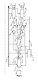
- Fig. 1 shows the block diagram of the circuit.
- Fig. 2 shows one of the possible diagrams of the sub-circuit connection.
- the subject of the new solution in general, is the use of an analyzing circuit consisting of sub-circuits for analyzing the individual protocols headers and of the data words counter on the data bus, and connected directly to the data bus, which transfers packets.
- the circuit contains sub-circuits connected into a structure, which corresponds to the individual anticipated protocols headers in the packets.
- the attached Fig. 1 shows the circuit solution of the whole connection.
- the presented diagram shows only one specific option for the sub-circuits connection, which is based on a specific set of supported protocols.
- the data outputs of the data bus 1 are interconnected both with the chain of N sub-circuits, here the sub-circuits 3 , 4 , 9 and 10 , for protocols headers analysis.
- the number of sub-circuits is given by the anticipated number of transmitted protocols.
- Another part of the connection is a counter 2 , the output 2.1 of which is interconnected with the inputs of the counter values of individual sub-circuits 3 , 4, 9 and 10.
- the first sub-circuit 3 connected to the input in the chain, has an activating input 3.1 and an input 3.2 of the position of the header start, the values of which are constant.
- the output 3.6 of the position of the next header start of the first sub-circuit 3 is interconnected both directly with the input of the second sub-circuit 4 and also with one input of all multiplexers 7 , 8 , the number of which is given by the number of sub-circuits inserted in the next section of the chain, here these are the two next sub-circuits 9 and 10 .
- the first sub-circuit 3 is then equipped with activating outputs 3.3 , 3.4 , 3.5 , the number of which is again given by the number of the sub-circuits inserted in the next section of the chain. Here they are three sub-circuits 4 , 9 , 10 .
- One such activating output 3.4 is here connected directly to the activating input of the second sub-circuit 4 and its other activating outputs 3.3 , 3.5 are connected to one input of the auxiliary logic circuits 5 , 6 , the number of which is given by the number of sub-circuits inserted in the next section of the chain, here then of the third sub-circuit 9 and the fourth sub-circuit 10 .
- To the second input of each of the auxiliary logic circuits 5 , 6 is connected one of the activating outputs 4.1 , 4.2 of the second sub-circuit 4 , while its output 4.3 of the position of the next header start is connected to the second input of the multiplexers 7 , 8 .
- the control inputs of the multiplexers 7 and 8 are connected to the control outputs 5.1 , 6.1 of the auxiliary logic circuits 5 , 6 .
- the activating outputs 5.2 , 6.2 of the auxiliary logic circuits 5 , 6 are connected to the activating input of the next sub-circuit 9 , or 10 respectively, relevant for them, while to their second input is connected the output 7.1 , 8.1 of the multiplexer 7 , or 8 respectively, relevant for them.
- the activating outputs 9.1 , 10.1 of the third activating circuit 9 and the fourth activating circuit 10 and the outputs 9.2 , 10.2 of the position of the next header start are a part of the output of the whole circuit.
- the chain thus created and here described consisting of sub-circuits is then in the same manner divided into branches based on the anticipated number of protocols, the headers of which are to be analyzed.
- the outputs of the whole circuit are then formed by the partial activating outputs 3.3 , 3.4 , 3.5 , 4.1 , 4.2 , 9.1 , 10.1 and the outputs 3.6 , 4.3 , 9.2 , 10.2 of the position of the next header start.
- the herewith given example of the preferred embodiment exploits one FPGA circuit for the creation of the data bus and the circuit consisting of individual sub-circuits 3 , 4 , 9 , 10 for the protocol headers analysis.
- each sub-circuit 3 , 4 , 9 , 10 is the activating signal carrying information if it was activated, it means if the relevant header in the packet is present, and the signal of the position of the header starts giving the sub-circuit the information about the position of the header start in the packet.
- the inputs of each sub-circuit 3 , 4 , 9 , 10 are the signals from the data bus 1 transferring the packets.
- Another input of each sub-circuit 3 , 4 , 9 , 10 is the value of the counter 2 of the current position in the packet.
- the outputs of each sub-circuit 3 , 4 , 9 , 10 are the activating signals carrying information about the detected type of the next header in the packet and the signal carrying information about position of the header start in the packet.
- Data bus 1 transfers packets.
- the counter 2 monitors traffic on the data bus 1 and provides at its output 2.1 to other sub-circuits analyses of headers, here to the sub-circuits 3 , 4 , 9 and 10 , information about the data bus 1 status, in particular about the position in the packet, which is at the given moment visible on the data bus 1 .
- All sub-circuits 3 , 4 , 9 and 10 of the header analysis have in their data input the data currently transferred from the data bus 1 and on their input of the counter value they have the output 2.1 of the counter 2 . Because the sub-circuit 3 is the first one, it has on its activating input 3.1 and on its input 3.2 positions of the header start of the constant. This first sub-circuit 3 starts working always at the beginning of the packet. In an Ethernet network this is the analyzer of the Ethernet protocol header. Its output is the output 3.6 of the position of the next header start, and the activating outputs 3.3 , 3.4 , 3.5 . This example therefore presumes that, after the header of the first protocol, three different headers of other protocols may follow.
- the second sub-circuit 4 has, to its activating input, directly connected the activating output 3.4 of the first sub-circuit 3 , and to its input of the position of the header start it has directly connected the output 3.6 of the sub-circuit 3 .
- This example therefore presumes that the header processed by the second sub-circuit 4 may follow in the packet only after the header of the protocol processed by the first sub-circuit 3 .
- the outputs of the second sub-circuit 4 are the output 4.3 of the position of the next header start, and the activating outputs 4.1 and 4.2 .
- This example therefore presumes that, after the header processed by the second sub-circuit 4 , two different protocol headers may follow in the packet.
- the third sub-circuit 9 has on its activating input, connected the activating output 5.2 of the first auxiliary logic circuit 5 , which sets the value of its activating output 5.2 as the logical sum of the activating output 3.3 of the first sub-circuit 3 and the activating output 4.1 of the second sub-circuit 4 , and, also on its input, of the position of the header start it has connected the output 7.1 of the first multiplexer 7 .
- the first multiplexer 7 switches to its output 7.1 one of the outputs 3.6 and 4.3 of the position of the next header start, based on the control input, which is set by the control output 5.1 of the first auxiliary logic circuit 5 , according to which of the sub-circuits 3 , 4 activates the third sub-circuit 9 .
- the output of the third sub-circuit 9 is a set of activating outputs 9.1 . which determines the type of the next protocol header, and the output 9.2 of the position of the next header start. Processing of the header following after the header of the protocol processed by the third sub-circuit 9 is not anticipated in this example and therefore the activating output 9.1 and the output 9.2 of the position of the next header start are used as the outputs of the whole circuit.
- the fourth sub-circuit 10 has on its activating input connected the activating output 6.2 of the second auxiliary logic circuit 6 , which sets the value of its activating output 6.2 as the logical sum of the activating output 3.5 of the first sub-circuit 3 and the activating output 4.2 of the second sub-circuit 4 , and also on its input the position of the header start it has connected the output 8.1 of the second multiplexer 8 .
- the second multiplexer 8 switches to its output 8.1 one of the outputs 3.6 and 4.3 of the position of the next header start, based on the control input, which is set by the control output 6.1 of the second auxiliary logic circuit 6 , according to which of the sub-circuits 3 , 4 activates the fourth sub-circuit 10 .
- the output of the fourth sub-circuit 10 is a set of activating outputs 10.1 , which determines the type of the next protocol header, and the output 10.2 of the position of the next header start. Processing of the header following after the header of the protocol processed by the fourth sub-circuit 10 is not anticipated in this example and therefore the activating output 10.1 and the output 10.2 of the position of the next header start are used as the outputs of the whole circuit.
- sub-circuits 3 , 4 , 9 , 10 perform the following functions in particular:
- the sub-circuits 3 , 4 , 9 and 10 send the obtained information to their outputs, from where they are connected to the inputs of the follow-up sub-circuits and also to the output of the whole circuit.
- the outputs of the whole circuit are the pieces of information obtained in sub-circuits 3 , 4 , 9 , 10 , especially the information about the presence of individual protocol headers and about their positions in the packet. This information can be further exploited, e.g. for a change of packet, by modifying some header, or possibly for the easy extraction of individual fields from the headers by means of multiplexers.
- each sub-circuit 3 , 4 , 9 and 10 depends on the protocol, which is to be processed by a given sub-circuit.
- Each sub-circuit contains summation units for calculation of the fields of interest positions in the packet.
- the input of each summation unit is the information about the position of the given header start in the packet (it means the sub-circuit input) and the constant defining of the position of the field of interest within the header. The value of the constant is based upon specification of the given protocol.
- the output of each summation unit is the position of the field of interest in the packet.
- Each sub-circuit further contains multiplexers for the selection of the packet fields of interest from the data bus.
- Each sub-circuit also contains registers for capturing the outputs from the multiplexers.
- the control input of the registers permitting writing to the registers is connected to the sub-circuit control logic. The values of the thus selected and stored fields of interest are brought to the inputs of comparators, which determine the type of the next header.
- each sub-circuit also contains the summation unit determining the start of the next protocol header. One input of the summation unit is connected to the input signals of the sub-circuit carrying information about the position of the relevant header start, the second input of the summation unit is connected to the signals carrying information about the header size.
- the protocol processed by the sub-circuit contains checking information
- the values of fields of interest are brought to the checking circuit.
- Outputs of the checking circuit may be exploited to report errors in the protocol.
- the output of the sub-circuit A carrying information about the position of next header start is connected to the inputs of the position of the header start of all sub-circuits B1..Bn.
- activating outputs of the sub-circuit A are then connected to the activating inputs of the sub-circuits B1..Bn in such a way that only that particular one of such sub-circuits, which is designed to process the detected type of protocol, will be activated.
- the input of the position of the header start of the sub-circuit A is connected from the output of the multiplexer, which is controlled by the activating outputs of the sub-circuits B1..Bn.
- the activating input of the sub-circuit A is then connected from the logic unit performing the logical sum of the activating outputs of the sub-circuits B1..Bn in such a way that the sub-circuit A is activated when some of the sub-circuits B1..Bn activates it.
- the attached Fig. 2 shows the circuit solution of a representative sub-circuit 4 for the analysis of the headers of one protocol, which follows after the first sub-circuit 3 .
- the presented example presumes that the length of the analyzed header is not constant, and that it can be calculated from some of the field in the header, further that the analyzed header contains a checking field, which, when used for checking, allows one to verify the protocol correctness, and also that the protocol admits two possibilities of the following protocol types.
- Data bus 1 transfers packets.
- One input of the second sub-circuit 4 is in fact the output 3.6 of the position of the next header start of the first sub-circuit 3 and determines the position of the analyzed header in the packet.
- the second input of the second sub-circuit 4 is the output 2.1 of the counter 2 and identifies the position in the packet, which is currently visible on the data bus 1 .
- the third input of the second sub-circuit 4 forms the activating output 3.4 of the first sub-circuit 3 , which determines whether the whole sub-circuit is active.
- Summation units 500 , 600 , 700 calculate the positions of the three fields of interest in the packet by summing the position of the analyzed header start on the output 3.6 with the constants 800 , 900 , 100 .
- the constants 800 , 900 , 100 are defined by the protocol specification.
- Multiplexers 11 , 12 , 13 are controlled by the outputs of the summation units 500 , 600 , 700 and select from the data bus 1 the fields of interest values.
- Registers 14 , 15 , 16 are controlled by the control circuit 17 and store the fields of interest values.
- Arithmetic unit 18 based on the value of the field of interest stored in the register 14 , calculates the length of the header of the processed protocol. The nature of the calculation is given by the protocol specification.
- the summation unit 19 sums the position of the processed header start from the input 3.6 with the length of the processed header and its output is the output 4.3 of the position of the next header start.
- Checking circuit 20 checks the correctness of the field of interest value stored in the register 15 and determines the value of the output 27 , which indicates an error in the protocol. The nature of the check is given by the protocol specification. Comparators 21 and 22 compare the field of interest value stored in the register 16 with constants 23 and 24 and send the information about the type of the next protocol header to the activating outputs 4.1 and 4.2 . Constants 23 and 24 are given by the protocol specification.
- Connection for the fast analysis of packet headers by a circuit connected directly to the data bus for the packets transfer according to the presented solution can find industrial applicability in the packet processing circuits. When compared to commonly applied solutions it allows to accelerate the packet headers analysis process, thus contributing to acceleration of the whole system.
Landscapes
- Engineering & Computer Science (AREA)
- Computer Networks & Wireless Communication (AREA)
- Signal Processing (AREA)
- Computer Security & Cryptography (AREA)
- Data Exchanges In Wide-Area Networks (AREA)
- Communication Control (AREA)
Abstract
Description
- The presented solution deals with the processing of packets in computer networks. The basic information about a packet is stored in its header, which needs to be analyzed prior to the further processing of the packet. Therefore, the solution deals with the sphere of telecommunications technology and services.
- Messages in computer networks are encapsulated into several layers of communication protocols. Each such protocol appends to a packet its own header. However, because the headers of some protocols are not of equal length and because the order of the headers in the packet usually is not known in advance, it is generally necessary to process the individual headers of the protocols one by one, while the result of the analysis of one header affects the analysis of the following header.
- Current solutions store the packet into the memory and subsequently they analyze the headers. However, due to data subordinations, they include a range of dependent memory accesses where the reading of a certain value from memory is preconditioned by the accomplished the reading of previous value. The shortest possible time of processing all the headers contained in the packet is then given by a product of the time for completing single memory operation and the number of memory operations.
- The disadvantages mentioned above are eliminate by the connection for the fast analysis of the packet headers by a circuit connected directly to the data bus for the packets transfer, according to the presented solution. Its principle is that the data outputs of the data bus are connected both to the chain of the N sub-circuits for protocols headers analysis, the number of which is given by the anticipated number of transferred protocols, and also to the counter, the output of which is interconnected with the inputs of the counter values of the individual sub-circuits. The first sub-circuit, connected to the input in the chain, has an activating input and an input of the position of the header start, the values of which are constant, and its output of the position of the next header start is interconnected both directly with the input of the second sub-circuit and also with one input of all multiplexers, the number of which is given by the number of sub-circuits inserted in the next section of the chain. This first sub-circuit is equipped with activating outputs, the number of which is given by the number of sub-circuits inserted in the next section of the chain. One activating output is connected directly to the activating input of the second sub-circuit and its other activating outputs are connected to one input of the auxiliary logic circuits, the number of which is given by the number of sub-circuits inserted in the next section of the chain. To the second input of each of the auxiliary logic circuits is connected one of the activating outputs of the second sub-circuit. The output of the position of the next header start of the second sub-circuit is connected to the second input of the multiplexers, and to their control inputs are connected the control outputs of the auxiliary logic circuits. Activating outputs of the auxiliary logic circuits are connected to the activating input of the next sub-circuit relevant for them, while to their second input is connected the output of the multiplexer relevant for them. The activating outputs of these successive sub-circuits, the number of which is given by the number of anticipated other types of protocol headers, and the outputs of the position of the next header start are part of the output of the whole circuit. The chain thus created from the sub-circuits is then, in the same manner divided into branches based on the anticipated number of protocols, the headers of which are to be analyzed. The outputs of the whole circuit are then formed by partial activating outputs and the outputs of the position of next header start.
- In a preferred embodiment, the described connection is created within the FPGA circuit, which serves to receive, process and send packets.
- The advantage of this solution is a faster analysis of the packet headers as opposed to placing a packet into the memory. Several layers of headers may be analyzed in every single clock cycle of the FPGA, because pieces of information transferred between individual sub-circuits are very simple. Another advantage is the option to change the supported protocols by changing the circuit structure. The sub-circuits for the individual headers analysis operate independently and have a unified interface, therefore the change of the circuit structure, and hence the change of supported protocols, is not a problem.
- The principle of the new solution is explained below and described using the attached drawing,
Fig. 1 , which shows the block diagram of the circuit.Fig. 2 then shows one of the possible diagrams of the sub-circuit connection. - The subject of the new solution, in general, is the use of an analyzing circuit consisting of sub-circuits for analyzing the individual protocols headers and of the data words counter on the data bus, and connected directly to the data bus, which transfers packets. The circuit contains sub-circuits connected into a structure, which corresponds to the individual anticipated protocols headers in the packets. The attached
Fig. 1 shows the circuit solution of the whole connection. The presented diagram shows only one specific option for the sub-circuits connection, which is based on a specific set of supported protocols. - In the connection, according to
Fig. 1 , the data outputs of thedata bus 1 are interconnected both with the chain of N sub-circuits, here thesub-circuits counter 2, the output 2.1 of which is interconnected with the inputs of the counter values ofindividual sub-circuits next sub-circuits sub-circuits third sub-circuit 9 and thefourth sub-circuit 10. To the second input of each of the auxiliary logic circuits 5, 6 is connected one of the activating outputs 4.1, 4.2 of the second sub-circuit 4, while its output 4.3 of the position of the next header start is connected to the second input of the multiplexers 7, 8. The control inputs of the multiplexers 7 and 8 are connected to the control outputs 5.1, 6.1 of the auxiliary logic circuits 5, 6. The activating outputs 5.2, 6.2 of the auxiliary logic circuits 5, 6 are connected to the activating input of thenext sub-circuit circuit 9 and the fourth activatingcircuit 10 and the outputs 9.2, 10.2 of the position of the next header start are a part of the output of the whole circuit. The chain thus created and here described consisting of sub-circuits is then in the same manner divided into branches based on the anticipated number of protocols, the headers of which are to be analyzed. The outputs of the whole circuit are then formed by the partial activating outputs 3.3, 3.4, 3.5, 4.1, 4.2, 9.1, 10.1 and the outputs 3.6, 4.3, 9.2, 10.2 of the position of the next header start. - The herewith given example of the preferred embodiment exploits one FPGA circuit for the creation of the data bus and the circuit consisting of
individual sub-circuits - In general, one can say that the input of each
sub-circuit sub-circuit data bus 1 transferring the packets. Another input of eachsub-circuit counter 2 of the current position in the packet. The outputs of eachsub-circuit -
Data bus 1 transfers packets. Thecounter 2 monitors traffic on thedata bus 1 and provides at its output 2.1 to other sub-circuits analyses of headers, here to thesub-circuits data bus 1 status, in particular about the position in the packet, which is at the given moment visible on thedata bus 1. - All
sub-circuits data bus 1 and on their input of the counter value they have the output 2.1 of thecounter 2. Because the sub-circuit 3 is the first one, it has on its activating input 3.1 and on its input 3.2 positions of the header start of the constant. This first sub-circuit 3 starts working always at the beginning of the packet. In an Ethernet network this is the analyzer of the Ethernet protocol header. Its output is the output 3.6 of the position of the next header start, and the activating outputs 3.3, 3.4, 3.5. This example therefore presumes that, after the header of the first protocol, three different headers of other protocols may follow. - The second sub-circuit 4 has, to its activating input, directly connected the activating output 3.4 of the first sub-circuit 3, and to its input of the position of the header start it has directly connected the output 3.6 of the sub-circuit 3. This example therefore presumes that the header processed by the second sub-circuit 4 may follow in the packet only after the header of the protocol processed by the first sub-circuit 3. The outputs of the second sub-circuit 4 are the output 4.3 of the position of the next header start, and the activating outputs 4.1 and 4.2. This example therefore presumes that, after the header processed by the second sub-circuit 4, two different protocol headers may follow in the packet.
- The
third sub-circuit 9 has on its activating input, connected the activating output 5.2 of the first auxiliary logic circuit 5, which sets the value of its activating output 5.2 as the logical sum of the activating output 3.3 of the first sub-circuit 3 and the activating output 4.1 of the second sub-circuit 4, and, also on its input, of the position of the header start it has connected the output 7.1 of the first multiplexer 7. The first multiplexer 7 switches to its output 7.1 one of the outputs 3.6 and 4.3 of the position of the next header start, based on the control input, which is set by the control output 5.1 of the first auxiliary logic circuit 5, according to which of the sub-circuits 3, 4 activates thethird sub-circuit 9. This example therefore presumes that the header of the protocol processed by thethird sub-circuit 9 may, in the packet, follow after the headers of protocols processed by the first sub-circuit 3 or the second sub-circuit 4. The output of thethird sub-circuit 9 is a set of activating outputs 9.1. which determines the type of the next protocol header, and the output 9.2 of the position of the next header start. Processing of the header following after the header of the protocol processed by thethird sub-circuit 9 is not anticipated in this example and therefore the activating output 9.1 and the output 9.2 of the position of the next header start are used as the outputs of the whole circuit. - The
fourth sub-circuit 10 has on its activating input connected the activating output 6.2 of the second auxiliary logic circuit 6, which sets the value of its activating output 6.2 as the logical sum of the activating output 3.5 of the first sub-circuit 3 and the activating output 4.2 of the second sub-circuit 4, and also on its input the position of the header start it has connected the output 8.1 of the second multiplexer 8. The second multiplexer 8 switches to its output 8.1 one of the outputs 3.6 and 4.3 of the position of the next header start, based on the control input, which is set by the control output 6.1 of the second auxiliary logic circuit 6, according to which of the sub-circuits 3, 4 activates thefourth sub-circuit 10. This example therefore presumes that the header of the protocol processed by the fourth sub-circuit 10 may, in the packet, follow after the headers of protocols processed by the first sub-circuit 3 or the second sub-circuit 4. The output of thefourth sub-circuit 10 is a set of activating outputs 10.1, which determines the type of the next protocol header, and the output 10.2 of the position of the next header start. Processing of the header following after the header of the protocol processed by thefourth sub-circuit 10 is not anticipated in this example and therefore the activating output 10.1 and the output 10.2 of the position of the next header start are used as the outputs of the whole circuit. - In summary, one can say that the
sub-circuits - Calculation of the fields of interest position in the packet by means of summation units, which sum the position of the header start in the packet (the sub-circuit input) with constant positions of the fields of interest in the header.
- Selection of fields of interest transferred on the
data bus 1 by means of multiplexers controlled by calculated positions of the fields in the packet. - Storing the fields of interest values to registers, which are controlled by the sub-circuit control logic.
- Determination of the next protocol type by comparing the stored values with constants.
- Determination of the next protocol header start by means of summation units, which sum the position of the header start of the current protocol (the sub-circuit input) with the size of this header.
- Checking of the protocol correctness by means of a dedicated circuit, for instance by calculation of the checksum.
- The
sub-circuits sub-circuits - Circuit implementation of each sub-circuit 3, 4, 9 and 10 depends on the protocol, which is to be processed by a given sub-circuit. Each sub-circuit contains summation units for calculation of the fields of interest positions in the packet. The input of each summation unit is the information about the position of the given header start in the packet (it means the sub-circuit input) and the constant defining of the position of the field of interest within the header. The value of the constant is based upon specification of the given protocol. The output of each summation unit is the position of the field of interest in the packet. Each sub-circuit further contains multiplexers for the selection of the packet fields of interest from the data bus. To the control inputs of multiplexers are connected the outputs of summation units, to the data inputs of the multiplexers are connected the signals from the data bus carrying the packets. Each sub-circuit also contains registers for capturing the outputs from the multiplexers. The control input of the registers permitting writing to the registers is connected to the sub-circuit control logic. The values of the thus selected and stored fields of interest are brought to the inputs of comparators, which determine the type of the next header.
- Provided that the size of the protocol header processed by the given sub-circuit is not constant, the values of the selected fields of interest are brought to the arithmetic unit determining the size of the header. The outputs of the arithmetic unit are the signals carrying information about the size of the header. In the opposite case it means, provided that the header size is constant, the signals carrying information about the size of the header are constant. Each sub-circuit also contains the summation unit determining the start of the next protocol header. One input of the summation unit is connected to the input signals of the sub-circuit carrying information about the position of the relevant header start, the second input of the summation unit is connected to the signals carrying information about the header size.
- Provided that the protocol processed by the sub-circuit contains checking information, the values of fields of interest are brought to the checking circuit. Outputs of the checking circuit may be exploited to report errors in the protocol.
- The mutual interconnection of the sub-circuits is made according to the following rules.
- If it is expected that the header of the protocol processed by the sub-circuit A will be in the packet followed by the header of one of the protocols processed by the sub-circuits B1..Bn, then the output of the sub-circuit A carrying information about the position of next header start is connected to the inputs of the position of the header start of all sub-circuits B1..Bn. activating outputs of the sub-circuit A are then connected to the activating inputs of the sub-circuits B1..Bn in such a way that only that particular one of such sub-circuits, which is designed to process the detected type of protocol, will be activated.
- If it is expected that the protocol processed by the sub-circuit A may in the packet follow after one of the protocols processed by the sub-circuits B1..Bn, then the input of the position of the header start of the sub-circuit A is connected from the output of the multiplexer, which is controlled by the activating outputs of the sub-circuits B1..Bn. The activating input of the sub-circuit A is then connected from the logic unit performing the logical sum of the activating outputs of the sub-circuits B1..Bn in such a way that the sub-circuit A is activated when some of the sub-circuits B1..Bn activates it.
- The attached
Fig. 2 shows the circuit solution of a representative sub-circuit 4 for the analysis of the headers of one protocol, which follows after the first sub-circuit 3. The presented example presumes that the length of the analyzed header is not constant, and that it can be calculated from some of the field in the header, further that the analyzed header contains a checking field, which, when used for checking, allows one to verify the protocol correctness, and also that the protocol admits two possibilities of the following protocol types.Data bus 1 transfers packets. One input of the second sub-circuit 4 is in fact the output 3.6 of the position of the next header start of the first sub-circuit 3 and determines the position of the analyzed header in the packet. The second input of the second sub-circuit 4 is the output 2.1 of thecounter 2 and identifies the position in the packet, which is currently visible on thedata bus 1. The third input of the second sub-circuit 4 forms the activating output 3.4 of the first sub-circuit 3, which determines whether the whole sub-circuit is active.Summation units constants constants Multiplexers summation units data bus 1 the fields of interest values.Registers control circuit 17 and store the fields of interest values.Arithmetic unit 18, based on the value of the field of interest stored in theregister 14, calculates the length of the header of the processed protocol. The nature of the calculation is given by the protocol specification. Thesummation unit 19 sums the position of the processed header start from the input 3.6 with the length of the processed header and its output is the output 4.3 of the position of the next header start. Checkingcircuit 20 checks the correctness of the field of interest value stored in theregister 15 and determines the value of theoutput 27, which indicates an error in the protocol. The nature of the check is given by the protocol specification.Comparators register 16 withconstants Constants - Connection for the fast analysis of packet headers by a circuit connected directly to the data bus for the packets transfer according to the presented solution can find industrial applicability in the packet processing circuits. When compared to commonly applied solutions it allows to accelerate the packet headers analysis process, thus contributing to acceleration of the whole system.
Claims (2)
- Connection for fast analysis of packet headers transferred via data bus characterized by the fact that the data bus (1) is by its data outputs interconnected both with the chain of N sub-circuits (3, 4, 9, 10) for analysis of protocols headers, the number of which is given by the anticipated number of transmitted protocols, and also with the counter (2), the output (2.1) of which is interconnected with the inputs of the counter values of individual sub-circuits (3, 4, 9, 10), where, to the input in the chain, is connected the first sub-circuit (3), which has an activating input (3.1) and an input (3.2) of the position of the header start, the values of which are constant, and by its output (3.6) of the position of next header start it is interconnected both directly with the input of the second sub-circuit (4) and also with one input of all multiplexers (7, 8), the number of which is given by the number of the sub-circuits (9, 10) inserted in the next section of the chain, and further it is equipped with activating outputs (3.3, 3.4, 3.5), the number of which is given by the number of the sub-circuits (4, 9, 10) inserted in the next section of the chain, from which one activating output (3.4) is connected directly to the activating input of the second sub-circuit (4) and other activating outputs (3.3, 3.5) are connected to one input of the auxiliary logic circuits (5, 6), the number of that input which is given by the number of sub-circuits (9, 10) inserted in the next section of the chain, where, to the second input of each of the auxiliary logic circuits (5, 6), is connected one of the activating outputs (4.1, 4.2) of the second sub-circuit (4), while its output (4.3) of the position of next header start is connected to the second input of the multiplexers (7, 8), having to their control inputs connected the control outputs (5.1, 6.1) of the auxiliary logic circuits (5, 6), and the activating outputs (5.2, 6.2) of the auxiliary logic circuits (5, 6) are connected to the activating input of next sub-circuit (9, 10) relevant for them, while, to their second input, is connected the output (7.1, 8.1) of the multiplexer (7, 8) relevant for them, and their activating outputs (9.1, 10.1), the number of which is given by the number of the anticipated next types of protocol headers, and the outputs (9.2, 10.2) of the position of the next header start are a part of the output of the whole circuit, while the chain thus created from the sub-circuits is then in the same manner divided into branches based on the anticipated number of protocols, the headers of which are to be analyzed, while the outputs of the whole circuit are formed by the partial activating outputs (3.3, 3.4, 3.5, 4.1, 4.2, 9.1, 10.1) and outputs (3.6, 4.3, 9.2, 10.2) of the position of the next header start.
- The connection according to claim 1 characterized by the fact that it is created within the FPGA circuit.
Applications Claiming Priority (1)
| Application Number | Priority Date | Filing Date | Title |
|---|---|---|---|
| CZ20120264A CZ2012264A3 (en) | 2012-04-17 | 2012-04-17 | Connection for fast analysis of packet headers transmitted over the data bus |
Publications (4)
| Publication Number | Publication Date |
|---|---|
| EP2654261A2 true EP2654261A2 (en) | 2013-10-23 |
| EP2654261A3 EP2654261A3 (en) | 2017-07-12 |
| EP2654261B1 EP2654261B1 (en) | 2017-12-20 |
| EP2654261B8 EP2654261B8 (en) | 2018-02-28 |
Family
ID=47891417
Family Applications (1)
| Application Number | Title | Priority Date | Filing Date |
|---|---|---|---|
| EP13158504.4A Not-in-force EP2654261B8 (en) | 2012-04-17 | 2013-03-11 | Circuit for the fast analysis of packet headers transferred via a data bus |
Country Status (3)
| Country | Link |
|---|---|
| US (1) | US8923300B2 (en) |
| EP (1) | EP2654261B8 (en) |
| CZ (1) | CZ2012264A3 (en) |
Cited By (2)
| Publication number | Priority date | Publication date | Assignee | Title |
|---|---|---|---|---|
| EP3258385A1 (en) * | 2016-06-14 | 2017-12-20 | Cesnet, Zájmové Sdruzení Právnickych Osob | Connection for quick search of regular expressions in data |
| WO2018120853A1 (en) * | 2016-12-30 | 2018-07-05 | 广州致远电子有限公司 | Bus signal protocol decoding method |
Families Citing this family (1)
| Publication number | Priority date | Publication date | Assignee | Title |
|---|---|---|---|---|
| CN114943197B (en) * | 2022-07-25 | 2022-09-23 | 青岛中科方德软件有限公司 | Simulation method and device of circuit control logic and electronic equipment |
Family Cites Families (7)
| Publication number | Priority date | Publication date | Assignee | Title |
|---|---|---|---|---|
| US6427169B1 (en) * | 1999-07-30 | 2002-07-30 | Intel Corporation | Parsing a packet header |
| JP2004040196A (en) * | 2002-06-28 | 2004-02-05 | Matsushita Electric Ind Co Ltd | Packet data processing device and packet data processing method |
| DE10260604B4 (en) * | 2002-12-23 | 2006-09-21 | Infineon Technologies Ag | Multi-channel processor |
| GB2443005A (en) * | 2006-07-19 | 2008-04-23 | Chronicle Solutions | Analysing network traffic by decoding a wide variety of protocols (or object types) of each packet |
| IL190134A (en) * | 2007-03-12 | 2012-07-31 | Marvell Israel Misl Ltd | Method and apparatus for determining locations of fields in a data unit |
| US20090028150A1 (en) * | 2007-07-26 | 2009-01-29 | Telefonaktiebolaget L M Ericsson (Publ) | Protocol-Independent Packet Header Analysis |
| EP2096832A1 (en) * | 2008-02-28 | 2009-09-02 | Deutsche Thomson OHG | Reconfigurable hardware-based parser for packet-oriented protocols |
-
2012
- 2012-04-17 CZ CZ20120264A patent/CZ2012264A3/en not_active IP Right Cessation
-
2013
- 2013-03-11 EP EP13158504.4A patent/EP2654261B8/en not_active Not-in-force
- 2013-04-03 US US13/855,792 patent/US8923300B2/en active Active
Non-Patent Citations (1)
| Title |
|---|
| None |
Cited By (2)
| Publication number | Priority date | Publication date | Assignee | Title |
|---|---|---|---|---|
| EP3258385A1 (en) * | 2016-06-14 | 2017-12-20 | Cesnet, Zájmové Sdruzení Právnickych Osob | Connection for quick search of regular expressions in data |
| WO2018120853A1 (en) * | 2016-12-30 | 2018-07-05 | 广州致远电子有限公司 | Bus signal protocol decoding method |
Also Published As
| Publication number | Publication date |
|---|---|
| US20130272307A1 (en) | 2013-10-17 |
| EP2654261B8 (en) | 2018-02-28 |
| CZ303954B6 (en) | 2013-07-10 |
| EP2654261A3 (en) | 2017-07-12 |
| CZ2012264A3 (en) | 2013-07-10 |
| US8923300B2 (en) | 2014-12-30 |
| EP2654261B1 (en) | 2017-12-20 |
Similar Documents
| Publication | Publication Date | Title |
|---|---|---|
| CN112653600A (en) | Network card performance testing method and device based on USB network card and electronic equipment | |
| CN110704714A (en) | Method and device for quickly indexing data of pcap file | |
| US10355968B2 (en) | Diagnosis of a network adapter during network operation | |
| US8923300B2 (en) | Connection for the fast analysis of packet headers transferred via data bus | |
| CN119201814A (en) | Signal transmission system, signal processing method and device, storage medium, electronic device and program product | |
| US11218397B2 (en) | Dual purpose NIC/PCIe protocol logic analyzer | |
| US10318453B2 (en) | Systems and methods for transmitting interrupts between nodes | |
| CN113872826A (en) | Network card port stability testing method, system, terminal and storage medium | |
| CN112241615A (en) | Method and system for detecting data balance time sequence and electronic equipment | |
| CN112311619B (en) | Network message delay detection method and device and electronic equipment | |
| US9542261B2 (en) | Methods, systems, and computer readable media for multi-packet cyclic redundancy check engine | |
| CN107092446A (en) | Multi-data synchronous harvester and multi-data synchronous acquisition system | |
| US10936515B2 (en) | Information processing system including data classification unit for reconstructing transfer data based on defined transfer codes | |
| CN111082980A (en) | Method and device for analyzing topological structure | |
| US10120019B2 (en) | Automated method for analyzing a board having a plurality of FPGA components | |
| CN110958079B (en) | Test method, device and system | |
| CN112882989A (en) | Protocol processing system and protocol data processing method | |
| CN116774020B (en) | Chip testing system, method, device and storage medium | |
| CN111106977B (en) | Data stream detection method, device and storage medium | |
| Denholm et al. | Network-level FPGA acceleration of low latency market data feed arbitration | |
| EP3258385B1 (en) | Connection for quick search of regular expressions in data | |
| CN117155853A (en) | Stored multipath aggregation method, multipath aggregation device and electronic equipment | |
| CN114172796A (en) | Fault positioning method and related device for communication network | |
| CN112737831A (en) | Firmware upgrade package processing method and device, electronic equipment and storage medium | |
| CN119420816B (en) | Flow tracking method and device, electronic equipment and storage medium |
Legal Events
| Date | Code | Title | Description |
|---|---|---|---|
| PUAI | Public reference made under article 153(3) epc to a published international application that has entered the european phase |
Free format text: ORIGINAL CODE: 0009012 |
|
| AK | Designated contracting states |
Kind code of ref document: A2 Designated state(s): AL AT BE BG CH CY CZ DE DK EE ES FI FR GB GR HR HU IE IS IT LI LT LU LV MC MK MT NL NO PL PT RO RS SE SI SK SM TR |
|
| AX | Request for extension of the european patent |
Extension state: BA ME |
|
| PUAL | Search report despatched |
Free format text: ORIGINAL CODE: 0009013 |
|
| RIC1 | Information provided on ipc code assigned before grant |
Ipc: H04L 29/06 20060101ALI20170531BHEP Ipc: H04L 12/741 20130101ALI20170531BHEP Ipc: H04L 12/26 20060101ALN20170531BHEP Ipc: H04L 12/40 20060101AFI20170531BHEP |
|
| AK | Designated contracting states |
Kind code of ref document: A3 Designated state(s): AL AT BE BG CH CY CZ DE DK EE ES FI FR GB GR HR HU IE IS IT LI LT LU LV MC MK MT NL NO PL PT RO RS SE SI SK SM TR |
|
| AX | Request for extension of the european patent |
Extension state: BA ME |
|
| REG | Reference to a national code |
Ref country code: DE Ref legal event code: R079 Ref document number: 602013030967 Country of ref document: DE Free format text: PREVIOUS MAIN CLASS: H04L0029060000 Ipc: H04L0012400000 |
|
| 17P | Request for examination filed |
Effective date: 20130315 |
|
| GRAP | Despatch of communication of intention to grant a patent |
Free format text: ORIGINAL CODE: EPIDOSNIGR1 |
|
| RIC1 | Information provided on ipc code assigned before grant |
Ipc: H04L 12/26 20060101ALN20170828BHEP Ipc: H04L 12/40 20060101AFI20170828BHEP Ipc: H04L 12/741 20130101ALI20170828BHEP Ipc: H04L 29/06 20060101ALI20170828BHEP |
|
| GRAS | Grant fee paid |
Free format text: ORIGINAL CODE: EPIDOSNIGR3 |
|
| INTG | Intention to grant announced |
Effective date: 20170922 |
|
| GRAA | (expected) grant |
Free format text: ORIGINAL CODE: 0009210 |
|
| AK | Designated contracting states |
Kind code of ref document: B1 Designated state(s): AL AT BE BG CH CY CZ DE DK EE ES FI FR GB GR HR HU IE IS IT LI LT LU LV MC MK MT NL NO PL PT RO RS SE SI SK SM TR |
|
| RAP1 | Party data changed (applicant data changed or rights of an application transferred) |
Owner name: CESNET, ZAJMOVE SDRUZENI PRAVNICKYCH OSOB |
|
| REG | Reference to a national code |
Ref country code: GB Ref legal event code: FG4D |
|
| REG | Reference to a national code |
Ref country code: CH Ref legal event code: EP |
|
| GRAT | Correction requested after decision to grant or after decision to maintain patent in amended form |
Free format text: ORIGINAL CODE: EPIDOSNCDEC |
|
| REG | Reference to a national code |
Ref country code: IE Ref legal event code: FG4D |
|
| REG | Reference to a national code |
Ref country code: AT Ref legal event code: REF Ref document number: 957307 Country of ref document: AT Kind code of ref document: T Effective date: 20180115 |
|
| REG | Reference to a national code |
Ref country code: DE Ref legal event code: R096 Ref document number: 602013030967 Country of ref document: DE |
|
| REG | Reference to a national code |
Ref country code: FR Ref legal event code: PLFP Year of fee payment: 6 |
|
| REG | Reference to a national code |
Ref country code: NL Ref legal event code: MP Effective date: 20171220 |
|
| PG25 | Lapsed in a contracting state [announced via postgrant information from national office to epo] |
Ref country code: SE Free format text: LAPSE BECAUSE OF FAILURE TO SUBMIT A TRANSLATION OF THE DESCRIPTION OR TO PAY THE FEE WITHIN THE PRESCRIBED TIME-LIMIT Effective date: 20171220 Ref country code: FI Free format text: LAPSE BECAUSE OF FAILURE TO SUBMIT A TRANSLATION OF THE DESCRIPTION OR TO PAY THE FEE WITHIN THE PRESCRIBED TIME-LIMIT Effective date: 20171220 Ref country code: LT Free format text: LAPSE BECAUSE OF FAILURE TO SUBMIT A TRANSLATION OF THE DESCRIPTION OR TO PAY THE FEE WITHIN THE PRESCRIBED TIME-LIMIT Effective date: 20171220 Ref country code: NO Free format text: LAPSE BECAUSE OF FAILURE TO SUBMIT A TRANSLATION OF THE DESCRIPTION OR TO PAY THE FEE WITHIN THE PRESCRIBED TIME-LIMIT Effective date: 20180320 |
|
| REG | Reference to a national code |
Ref country code: LT Ref legal event code: MG4D |
|
| REG | Reference to a national code |
Ref country code: AT Ref legal event code: MK05 Ref document number: 957307 Country of ref document: AT Kind code of ref document: T Effective date: 20171220 |
|
| PG25 | Lapsed in a contracting state [announced via postgrant information from national office to epo] |
Ref country code: BG Free format text: LAPSE BECAUSE OF FAILURE TO SUBMIT A TRANSLATION OF THE DESCRIPTION OR TO PAY THE FEE WITHIN THE PRESCRIBED TIME-LIMIT Effective date: 20180320 Ref country code: LV Free format text: LAPSE BECAUSE OF FAILURE TO SUBMIT A TRANSLATION OF THE DESCRIPTION OR TO PAY THE FEE WITHIN THE PRESCRIBED TIME-LIMIT Effective date: 20171220 Ref country code: GR Free format text: LAPSE BECAUSE OF FAILURE TO SUBMIT A TRANSLATION OF THE DESCRIPTION OR TO PAY THE FEE WITHIN THE PRESCRIBED TIME-LIMIT Effective date: 20180321 Ref country code: HR Free format text: LAPSE BECAUSE OF FAILURE TO SUBMIT A TRANSLATION OF THE DESCRIPTION OR TO PAY THE FEE WITHIN THE PRESCRIBED TIME-LIMIT Effective date: 20171220 Ref country code: RS Free format text: LAPSE BECAUSE OF FAILURE TO SUBMIT A TRANSLATION OF THE DESCRIPTION OR TO PAY THE FEE WITHIN THE PRESCRIBED TIME-LIMIT Effective date: 20171220 |
|
| PG25 | Lapsed in a contracting state [announced via postgrant information from national office to epo] |
Ref country code: NL Free format text: LAPSE BECAUSE OF FAILURE TO SUBMIT A TRANSLATION OF THE DESCRIPTION OR TO PAY THE FEE WITHIN THE PRESCRIBED TIME-LIMIT Effective date: 20171220 |
|
| PG25 | Lapsed in a contracting state [announced via postgrant information from national office to epo] |
Ref country code: ES Free format text: LAPSE BECAUSE OF FAILURE TO SUBMIT A TRANSLATION OF THE DESCRIPTION OR TO PAY THE FEE WITHIN THE PRESCRIBED TIME-LIMIT Effective date: 20171220 Ref country code: EE Free format text: LAPSE BECAUSE OF FAILURE TO SUBMIT A TRANSLATION OF THE DESCRIPTION OR TO PAY THE FEE WITHIN THE PRESCRIBED TIME-LIMIT Effective date: 20171220 Ref country code: CY Free format text: LAPSE BECAUSE OF FAILURE TO SUBMIT A TRANSLATION OF THE DESCRIPTION OR TO PAY THE FEE WITHIN THE PRESCRIBED TIME-LIMIT Effective date: 20171220 Ref country code: SK Free format text: LAPSE BECAUSE OF FAILURE TO SUBMIT A TRANSLATION OF THE DESCRIPTION OR TO PAY THE FEE WITHIN THE PRESCRIBED TIME-LIMIT Effective date: 20171220 Ref country code: CZ Free format text: LAPSE BECAUSE OF FAILURE TO SUBMIT A TRANSLATION OF THE DESCRIPTION OR TO PAY THE FEE WITHIN THE PRESCRIBED TIME-LIMIT Effective date: 20171220 |
|
| PG25 | Lapsed in a contracting state [announced via postgrant information from national office to epo] |
Ref country code: SM Free format text: LAPSE BECAUSE OF FAILURE TO SUBMIT A TRANSLATION OF THE DESCRIPTION OR TO PAY THE FEE WITHIN THE PRESCRIBED TIME-LIMIT Effective date: 20171220 Ref country code: IT Free format text: LAPSE BECAUSE OF FAILURE TO SUBMIT A TRANSLATION OF THE DESCRIPTION OR TO PAY THE FEE WITHIN THE PRESCRIBED TIME-LIMIT Effective date: 20171220 Ref country code: AT Free format text: LAPSE BECAUSE OF FAILURE TO SUBMIT A TRANSLATION OF THE DESCRIPTION OR TO PAY THE FEE WITHIN THE PRESCRIBED TIME-LIMIT Effective date: 20171220 Ref country code: IS Free format text: LAPSE BECAUSE OF FAILURE TO SUBMIT A TRANSLATION OF THE DESCRIPTION OR TO PAY THE FEE WITHIN THE PRESCRIBED TIME-LIMIT Effective date: 20180420 Ref country code: RO Free format text: LAPSE BECAUSE OF FAILURE TO SUBMIT A TRANSLATION OF THE DESCRIPTION OR TO PAY THE FEE WITHIN THE PRESCRIBED TIME-LIMIT Effective date: 20171220 Ref country code: PL Free format text: LAPSE BECAUSE OF FAILURE TO SUBMIT A TRANSLATION OF THE DESCRIPTION OR TO PAY THE FEE WITHIN THE PRESCRIBED TIME-LIMIT Effective date: 20171220 |
|
| REG | Reference to a national code |
Ref country code: DE Ref legal event code: R097 Ref document number: 602013030967 Country of ref document: DE |
|
| PLBE | No opposition filed within time limit |
Free format text: ORIGINAL CODE: 0009261 |
|
| STAA | Information on the status of an ep patent application or granted ep patent |
Free format text: STATUS: NO OPPOSITION FILED WITHIN TIME LIMIT |
|
| 26N | No opposition filed |
Effective date: 20180921 |
|
| PG25 | Lapsed in a contracting state [announced via postgrant information from national office to epo] |
Ref country code: DK Free format text: LAPSE BECAUSE OF FAILURE TO SUBMIT A TRANSLATION OF THE DESCRIPTION OR TO PAY THE FEE WITHIN THE PRESCRIBED TIME-LIMIT Effective date: 20171220 Ref country code: MC Free format text: LAPSE BECAUSE OF FAILURE TO SUBMIT A TRANSLATION OF THE DESCRIPTION OR TO PAY THE FEE WITHIN THE PRESCRIBED TIME-LIMIT Effective date: 20171220 |
|
| REG | Reference to a national code |
Ref country code: BE Ref legal event code: MM Effective date: 20180331 |
|
| PG25 | Lapsed in a contracting state [announced via postgrant information from national office to epo] |
Ref country code: LU Free format text: LAPSE BECAUSE OF NON-PAYMENT OF DUE FEES Effective date: 20180311 |
|
| PG25 | Lapsed in a contracting state [announced via postgrant information from national office to epo] |
Ref country code: SI Free format text: LAPSE BECAUSE OF FAILURE TO SUBMIT A TRANSLATION OF THE DESCRIPTION OR TO PAY THE FEE WITHIN THE PRESCRIBED TIME-LIMIT Effective date: 20171220 Ref country code: BE Free format text: LAPSE BECAUSE OF NON-PAYMENT OF DUE FEES Effective date: 20180331 |
|
| PG25 | Lapsed in a contracting state [announced via postgrant information from national office to epo] |
Ref country code: MT Free format text: LAPSE BECAUSE OF NON-PAYMENT OF DUE FEES Effective date: 20180311 |
|
| PG25 | Lapsed in a contracting state [announced via postgrant information from national office to epo] |
Ref country code: TR Free format text: LAPSE BECAUSE OF FAILURE TO SUBMIT A TRANSLATION OF THE DESCRIPTION OR TO PAY THE FEE WITHIN THE PRESCRIBED TIME-LIMIT Effective date: 20171220 |
|
| PGFP | Annual fee paid to national office [announced via postgrant information from national office to epo] |
Ref country code: GB Payment date: 20200211 Year of fee payment: 8 Ref country code: IE Payment date: 20200211 Year of fee payment: 8 Ref country code: DE Payment date: 20200213 Year of fee payment: 8 |
|
| PG25 | Lapsed in a contracting state [announced via postgrant information from national office to epo] |
Ref country code: HU Free format text: LAPSE BECAUSE OF FAILURE TO SUBMIT A TRANSLATION OF THE DESCRIPTION OR TO PAY THE FEE WITHIN THE PRESCRIBED TIME-LIMIT; INVALID AB INITIO Effective date: 20130311 Ref country code: PT Free format text: LAPSE BECAUSE OF FAILURE TO SUBMIT A TRANSLATION OF THE DESCRIPTION OR TO PAY THE FEE WITHIN THE PRESCRIBED TIME-LIMIT Effective date: 20171220 |
|
| PGFP | Annual fee paid to national office [announced via postgrant information from national office to epo] |
Ref country code: CH Payment date: 20200214 Year of fee payment: 8 |
|
| PG25 | Lapsed in a contracting state [announced via postgrant information from national office to epo] |
Ref country code: MK Free format text: LAPSE BECAUSE OF NON-PAYMENT OF DUE FEES Effective date: 20171220 |
|
| PGFP | Annual fee paid to national office [announced via postgrant information from national office to epo] |
Ref country code: FR Payment date: 20200211 Year of fee payment: 8 |
|
| PG25 | Lapsed in a contracting state [announced via postgrant information from national office to epo] |
Ref country code: AL Free format text: LAPSE BECAUSE OF FAILURE TO SUBMIT A TRANSLATION OF THE DESCRIPTION OR TO PAY THE FEE WITHIN THE PRESCRIBED TIME-LIMIT Effective date: 20171220 |
|
| REG | Reference to a national code |
Ref country code: DE Ref legal event code: R119 Ref document number: 602013030967 Country of ref document: DE |
|
| REG | Reference to a national code |
Ref country code: CH Ref legal event code: PL |
|
| GBPC | Gb: european patent ceased through non-payment of renewal fee |
Effective date: 20210311 |
|
| PG25 | Lapsed in a contracting state [announced via postgrant information from national office to epo] |
Ref country code: DE Free format text: LAPSE BECAUSE OF NON-PAYMENT OF DUE FEES Effective date: 20211001 Ref country code: GB Free format text: LAPSE BECAUSE OF NON-PAYMENT OF DUE FEES Effective date: 20210311 Ref country code: FR Free format text: LAPSE BECAUSE OF NON-PAYMENT OF DUE FEES Effective date: 20210331 Ref country code: IE Free format text: LAPSE BECAUSE OF NON-PAYMENT OF DUE FEES Effective date: 20210311 Ref country code: CH Free format text: LAPSE BECAUSE OF NON-PAYMENT OF DUE FEES Effective date: 20210331 Ref country code: LI Free format text: LAPSE BECAUSE OF NON-PAYMENT OF DUE FEES Effective date: 20210331 |