EP2654094A1 - Polymer composite piezoelectric body and method for producing same - Google Patents
Polymer composite piezoelectric body and method for producing same Download PDFInfo
- Publication number
- EP2654094A1 EP2654094A1 EP11848696.8A EP11848696A EP2654094A1 EP 2654094 A1 EP2654094 A1 EP 2654094A1 EP 11848696 A EP11848696 A EP 11848696A EP 2654094 A1 EP2654094 A1 EP 2654094A1
- Authority
- EP
- European Patent Office
- Prior art keywords
- cyanoethyl
- piezoelectric body
- polymer
- composite
- polymer composite
- Prior art date
- Legal status (The legal status is an assumption and is not a legal conclusion. Google has not performed a legal analysis and makes no representation as to the accuracy of the status listed.)
- Granted
Links
Images


Classifications
-
- H—ELECTRICITY
- H10—SEMICONDUCTOR DEVICES; ELECTRIC SOLID-STATE DEVICES NOT OTHERWISE PROVIDED FOR
- H10N—ELECTRIC SOLID-STATE DEVICES NOT OTHERWISE PROVIDED FOR
- H10N30/00—Piezoelectric or electrostrictive devices
- H10N30/704—Piezoelectric or electrostrictive devices based on piezoelectric or electrostrictive films or coatings
-
- H—ELECTRICITY
- H10—SEMICONDUCTOR DEVICES; ELECTRIC SOLID-STATE DEVICES NOT OTHERWISE PROVIDED FOR
- H10N—ELECTRIC SOLID-STATE DEVICES NOT OTHERWISE PROVIDED FOR
- H10N30/00—Piezoelectric or electrostrictive devices
- H10N30/01—Manufacture or treatment
- H10N30/09—Forming piezoelectric or electrostrictive materials
- H10N30/098—Forming organic materials
-
- C—CHEMISTRY; METALLURGY
- C08—ORGANIC MACROMOLECULAR COMPOUNDS; THEIR PREPARATION OR CHEMICAL WORKING-UP; COMPOSITIONS BASED THEREON
- C08K—Use of inorganic or non-macromolecular organic substances as compounding ingredients
- C08K3/00—Use of inorganic substances as compounding ingredients
- C08K3/02—Elements
- C08K3/04—Carbon
-
- C—CHEMISTRY; METALLURGY
- C08—ORGANIC MACROMOLECULAR COMPOUNDS; THEIR PREPARATION OR CHEMICAL WORKING-UP; COMPOSITIONS BASED THEREON
- C08K—Use of inorganic or non-macromolecular organic substances as compounding ingredients
- C08K3/00—Use of inorganic substances as compounding ingredients
- C08K3/02—Elements
- C08K3/08—Metals
-
- C—CHEMISTRY; METALLURGY
- C08—ORGANIC MACROMOLECULAR COMPOUNDS; THEIR PREPARATION OR CHEMICAL WORKING-UP; COMPOSITIONS BASED THEREON
- C08K—Use of inorganic or non-macromolecular organic substances as compounding ingredients
- C08K3/00—Use of inorganic substances as compounding ingredients
- C08K3/18—Oxygen-containing compounds, e.g. metal carbonyls
- C08K3/24—Acids; Salts thereof
-
- C—CHEMISTRY; METALLURGY
- C08—ORGANIC MACROMOLECULAR COMPOUNDS; THEIR PREPARATION OR CHEMICAL WORKING-UP; COMPOSITIONS BASED THEREON
- C08L—COMPOSITIONS OF MACROMOLECULAR COMPOUNDS
- C08L29/00—Compositions of homopolymers or copolymers of compounds having one or more unsaturated aliphatic radicals, each having only one carbon-to-carbon double bond, and at least one being terminated by an alcohol, ether, aldehydo, ketonic, acetal or ketal radical; Compositions of hydrolysed polymers of esters of unsaturated alcohols with saturated carboxylic acids; Compositions of derivatives of such polymers
- C08L29/02—Homopolymers or copolymers of unsaturated alcohols
- C08L29/04—Polyvinyl alcohol; Partially hydrolysed homopolymers or copolymers of esters of unsaturated alcohols with saturated carboxylic acids
-
- H—ELECTRICITY
- H10—SEMICONDUCTOR DEVICES; ELECTRIC SOLID-STATE DEVICES NOT OTHERWISE PROVIDED FOR
- H10N—ELECTRIC SOLID-STATE DEVICES NOT OTHERWISE PROVIDED FOR
- H10N30/00—Piezoelectric or electrostrictive devices
- H10N30/01—Manufacture or treatment
- H10N30/04—Treatments to modify a piezoelectric or electrostrictive property, e.g. polarisation characteristics, vibration characteristics or mode tuning
- H10N30/045—Treatments to modify a piezoelectric or electrostrictive property, e.g. polarisation characteristics, vibration characteristics or mode tuning by polarising
-
- H—ELECTRICITY
- H10—SEMICONDUCTOR DEVICES; ELECTRIC SOLID-STATE DEVICES NOT OTHERWISE PROVIDED FOR
- H10N—ELECTRIC SOLID-STATE DEVICES NOT OTHERWISE PROVIDED FOR
- H10N30/00—Piezoelectric or electrostrictive devices
- H10N30/01—Manufacture or treatment
- H10N30/07—Forming of piezoelectric or electrostrictive parts or bodies on an electrical element or another base
- H10N30/074—Forming of piezoelectric or electrostrictive parts or bodies on an electrical element or another base by depositing piezoelectric or electrostrictive layers, e.g. aerosol or screen printing
- H10N30/077—Forming of piezoelectric or electrostrictive parts or bodies on an electrical element or another base by depositing piezoelectric or electrostrictive layers, e.g. aerosol or screen printing by liquid phase deposition
-
- H—ELECTRICITY
- H10—SEMICONDUCTOR DEVICES; ELECTRIC SOLID-STATE DEVICES NOT OTHERWISE PROVIDED FOR
- H10N—ELECTRIC SOLID-STATE DEVICES NOT OTHERWISE PROVIDED FOR
- H10N30/00—Piezoelectric or electrostrictive devices
- H10N30/01—Manufacture or treatment
- H10N30/09—Forming piezoelectric or electrostrictive materials
- H10N30/092—Forming composite materials
-
- H—ELECTRICITY
- H10—SEMICONDUCTOR DEVICES; ELECTRIC SOLID-STATE DEVICES NOT OTHERWISE PROVIDED FOR
- H10N—ELECTRIC SOLID-STATE DEVICES NOT OTHERWISE PROVIDED FOR
- H10N30/00—Piezoelectric or electrostrictive devices
- H10N30/80—Constructional details
- H10N30/85—Piezoelectric or electrostrictive active materials
- H10N30/852—Composite materials, e.g. having 1-3 or 2-2 type connectivity
-
- H—ELECTRICITY
- H10—SEMICONDUCTOR DEVICES; ELECTRIC SOLID-STATE DEVICES NOT OTHERWISE PROVIDED FOR
- H10N—ELECTRIC SOLID-STATE DEVICES NOT OTHERWISE PROVIDED FOR
- H10N30/00—Piezoelectric or electrostrictive devices
- H10N30/80—Constructional details
- H10N30/85—Piezoelectric or electrostrictive active materials
- H10N30/857—Macromolecular compositions
Definitions
- the present invention relates to polymer composite piezoelectric bodies suitable for piezoelectric devices, sensors, ultrasound probes, electric power generating devices, vibration-powered generators, and the like, as well as methods of manufacturing such piezoelectric bodies.
- the present invention is particularly directed to a polymer composite piezoelectric body having piezoelectric particles uniformly mixed by dispersion in a polymer matrix composed of cyanoethylated polyvinyl alcohol, and a method of manufacturing such a piezoelectric body.
- Polymeric piezoelectric materials are those piezoelectric materials which have characteristics inherent to polymer materials, such as good flexibility, high-impact properties, ease of machining, and ability to have an increased area, which are high in power output constant (piezoelectric "g" constant) as compared with inorganic piezoelectric materials, and which are similar in acoustic impedance to the human body or water, so that their application to various sensors, or ultrasonic transducers such as an ultrasound probe and a hydrophone, vibration controllers (dampers), or to the vibration energy harvesting is expected nowadays.
- piezoelectric materials which have a piezoelectric strain constant ("d" constant) as an index to the strain amount per unit electric field (signal sending ability) and a "g” constant as an index to the strength of electric field generated per unit stress (signal receiving ability) both favorable in magnitude, or are excellent in balance between the constants.
- d piezoelectric strain constant
- g strength of electric field generated per unit stress
- the polymeric piezoelectric materials are known to include piezoelectric polymers, namely, the polymers piezoelectric in themselves as typified by polyvinylidene fluoride (PVDF), which are low in "d” constant as compared with inorganic piezoelectric materials and, accordingly, cannot effect adequate performance if used for the above applications as a polymeric piezoelectric material.
- PVDF polyvinylidene fluoride
- the polymer composite piezoelectric which is obtained by using a polymer material as a matrix and mixing an inorganic piezoelectric into the polymer matrix to produce a piezoelectric composite is a piezoelectric allowed to have the above advantages typical of polymer materials and an excellent piezoelectric performance ("d" constant) of the inorganic piezoelectric in an effective manner.
- Polymer composite piezoelectrics are claiming attention as a piezoelectric variable in material design with different applications by changing the type of a polymer serving as a matrix, the type or composition of the inorganic piezoelectric, the connectivity, or the shape, or the blending ratio. In consequence, a variety of polymer composite piezoelectrics have been proposed (see Patent Literature 1, for instance).
- a piezoelectric with high piezoelectric performance is used for a polymer composite piezoelectric, so that use is chiefly made of lead-based piezoelectric materials having extremely high "d" constants, such as lead zirconate titanate (Pb(Zr,Ti)O 3 : PZT).
- lead-based piezoelectric materials having extremely high "d" constants such as lead zirconate titanate (Pb(Zr,Ti)O 3 : PZT).
- Patent Literature 1 discloses the electronic component material having good dielectricity, pyroelectricity and piezoelectricity that is obtained by forming a composite product by uniformly mixing by dispersion a ferroelectric substance consisting of ceramic particles with a perovskite-type crystal structure in a dielectric binder composed of cyanoethylated cellulose and/or cyanoethylated pullulan, and applying a specified voltage to the composite product.
- the composite product as a combination of cyanoethylated pullulan and piezoelectric particles that is formed on a substrate by casting is liable to undergo, during subsequent poling (polarization treatment) conducted thereon, dielectric breakdown at spots with low withstand voltages caused therein by an uneven thickness or nonuniform particle dispersion, which makes large-area production difficult.
- cyanoethylated pullulan has a poor adhesion to other types of materials, and is liable to have troubles, such as cracking and peeling off, during the step of drying following the casting, which also makes large-area production difficult.
- An object of the present invention is to solve the above problems with the prior art so as to provide a method of manufacturing a polymer composite piezoelectric body, allowing manufacture with high yields involving neither dielectric breakdown nor peeling off even for polymer composite piezoelectric bodies of large area, and a polymer composite piezoelectric body manufactured by such a method.
- the present invention provides a polymer composite piezoelectric body obtained by conducting poling on a composite having piezoelectric particles uniformly mixed by dispersion in a polymer matrix comprising cyanoethylated polyvinyl alcohol (cyanoethylated PVA).
- cyanoethylated PVA cyanoethylated polyvinyl alcohol
- the polymer matrix is cyanoethylated polyvinyl alcohol to which is added at least one high-dielectric or ferroelectric polymer out of fluoropolymers, such as polyvinylidene fluoride, vinylidne fluoride - tetrafluoroethylene copolymer, vinylidene fluoride - trifluoroethylene copolymer, polyvinylidene fluoride - trifluoroethylene copolymer, and polyvinylidene fluoride - tetrafluoroethylene copolymer; or out of cyano group- or cyanoethyl group-containing polymers, such as vinylidene cyanate - vinyl acetate copolymer, cyanoethyl cellulose, cyanoethyl hydroxysaccharose, cyanoethyl hydroxycellulose, cyanoethyl hydroxypullulan, cyanoethyl meth
- fluoropolymers such
- the piezoelectric particles comprise ceramic particles having a perovskite-type crystal structure.
- the ceramic particles are composed of, for instance, lead zirconate titanate, lead lanthanate zirconate titanate, barium titanate, or a solid solution of barium titanate and bismuth ferrite.
- the present invention also provides a method of manufacturing a polymer composite piezoelectric body, comprising the steps of: forming, on a substrate, a composite having piezoelectric particles uniformly mixed by dispersion in a polymer matrix comprising cyanoethylated polyvinyl alcohol; and conducting poling on the composite.
- the step of forming a composite includes casting a piezoelectric particle-containing coating solution onto the substrate, with the coating solution being obtained by dispersing the piezoelectric particles in an organic solvent in which a dielectric binder comprising the cyanoethylated polyvinyl alcohol has been dissolved; and then evaporating the organic solvent so as to form a coating film.
- the substrate is preferably any of various metal sheets, or a polymer film provided on its at least one face with a coating/foil of metal, such as aluminum or copper, serving as a lower electrode.
- a composite product comprising an organic polymer and conductive particles may also be used for the substrate.
- the organic polymer is preferably composed of at least one out of a thermoplastic resin, a thermoplastic elastomer, and a vulcanized rubber.
- the conductive particles C, Pd, Fe, Sn, Al, Ni, Pt, Au, Ag, Cu, Cr, Mo, or an alloy thereof is used.
- the method of casting the coating solution onto the substrate may be any of conventional solution casting methods including doctor coating and blade coating.
- a composite formed by a conventional casting method generally has a thickness of about 50 to 100 ⁇ m.
- the step of conducting poling preferably includes providing an upper electrode on a surface of the composite that is opposite with a face in contact with the substrate, then heating the composite to a specified temperature, and applying a direct electric field between the substrate (lower electrode) and the upper electrode for a specified period of time.
- the step of conducting poling includes the step of applying a specified direct electric field between the substrate (lower electrode) and a corona electrode in rod or wire form, which is positioned at a specified distance from a surface of the composite that is opposite with a face in contact with the substrate, and which is movable along the surface of the composite, while heating the composite to a specified temperature and keeping it at that temperature, so as to cause corona discharge; and, under the corona discharge, causing the corona electrode to move relatively to the composite along the surface of the composite.
- the temperature to which the composite is to be heated during the poling is preferably 60 to 120°C.
- the piezoelectric particles comprise ceramic particles having a perovskite-type crystal structure.
- the ceramic particles are composed of, for instance, lead zirconate titanate, lead lanthanate zirconate titanate, barium titanate, or a solid solution of barium titanate and bismuth ferrite.
- the dielectric binder may be cyanoethylated polyvinyl alcohol to which is added at least one high-dielectric or ferroelectric polymer out of fluoropolymers, such as polyvinylidene fluoride, vinylidne fluoride - tetrafluoroethylene copolymer, vinylidene fluoride - trifluoroethylene copolymer, polyvinylidene fluoride - trifluoroethylene copolymer, and polyvinylidene fluoride - tetrafluoroethylene copolymer; or out of cyano group- or cyanoethyl group-containing polymers, such as vinylidene cyanate - vinyl acetate copolymer, cyanoethyl cellulose, cyanoethyl hydroxysaccharose, cyanoethyl hydroxycellulose, cyanoethyl hydroxypullulan, cyanoethyl methacrylate, cyanoe
- cyanoethylated PVA having a softening temperature in the vicinity of room temperature is used for a polymer matrix
- mechanical constraints on piezoelectric particles can be reduced at relatively low heating temperatures with no increase in leak current.
- a field strength required for poling is significantly reduced, which makes it possible to suppress dielectric breakdown even if there are spots with low withstand voltages caused in a composite by an uneven thickness or nonuniform dispersion of piezoelectric particles.
- cyanoethylated PVA having a good adhesion to other types of materials such troubles as cracking and peeling off are suppressed during the step of drying following the casting.
- cyanoethylated PVA for a polymer matrix thus makes it possible to attain the method of manufacturing a polymer composite piezoelectric body that allows manufacture with high yields involving neither dielectric breakdown nor peeling off even for polymer composite piezoelectric bodies of large area, and the polymer composite piezoelectric body which is free from dielectric breakdown and peeling off even if large in area.
- Fig. 1 is a schematic diagram showing a polymer composite piezoelectric body as an embodiment of the present invention.
- a polymer composite piezoelectric body (piezoelectric composite) 10 shown in Fig. 1 is obtained by conducting poling on a composite 16 having piezoelectric particles 14 of a ferroelectric material uniformly dispersed in a polymer matrix 12 composed of cyanoethylated polyvinyl alcohol (hereafter also referred to as "cyanoethylated PVA").
- the polymer composite piezoelectric body 10 includes a lower electrode 20 and an upper electrode 22, with the former being provided on a bottom face 16b, and the latter on a top face 16a, of the composite 16 for instance.
- the polymer matrix 12 is not limited to cyanoethylated PVA alone but may be the cyanoethylated PVA to which is added at least one high-dielectric or ferroelectric polymer out of fluoropolymers, such as polyvinylidene fluoride, vinylidne fluoride - tetrafluoroethylene copolymer, vinylidene fluoride - trifluoroethylene copolymer, polyvinylidene fluoride - trifluoroethylene copolymer, and polyvinylidene fluoride - tetrafluoroethylene copolymer; or out of cyano group- or cyanoethyl group-containing polymers, such as vinylidene cyanate - vinyl acetate copolymer, cyanoethyl cellulose, cyanoethyl hydroxysaccharose, cyanoethyl hydroxycellulose, cyanoethyl hydroxypullulan, cyan
- the piezoelectric particles 14 are comprised of ceramic particles having a perovskite-type crystal structure.
- the ceramic particles which constitute the piezoelectric particles 14 are composed of lead zirconate titanate (PZT), lead lanthanate zirconate titanate (PLZT), barium titanate (BaTiO 3 ) or a solid solution (BFBT) of barium titanate and bismuth ferrite (BiFe 3 ), for instance.
- the polymer composite piezoelectric body 10 is excellent in flexibility because the polymer matrix 12 is used for it.
- the polymer composite piezoelectric body 10 may include a conductive or nonconductive substrate provided on at least one out of the top face 16a and the bottom face 16b of the composite 16.
- the substrate is preferably flexible.
- the manufacturing method of the polymer composite piezoelectric body 10 is described in reference to Fig. 2 .
- the lower electrode 20 of conductive nature is initially prepared.
- the lower electrode 20 may also be a conductive film formed on another substrate (not shown) by sputtering or the like.
- the composite 16 is formed on a surface 20a of the lower electrode 20.
- a specified amount of the piezoelectric particles 14 are dispersed uniformly in an organic solvent, such as methyl ethyl ketone, cyclohexanone or dimethylformamide (DMF), with a dielectric binder dissolved therein, which is composed of cyanoethylated PVA and adapted to serve as the polymer matrix 12, so as to obtain a piezoelectric particle-containing coating solution, and the coating solution is cast onto the surface 20a of the lower electrode 20, then the organic solvent is evaporated to form the composite 16.
- an organic solvent such as methyl ethyl ketone, cyclohexanone or dimethylformamide (DMF)
- the composite 16 may be formed by, apart from the method by casting as above, a method by extrusion using a melted dielectric binder with piezoelectric particles dispersed therein.
- the dielectric binder to be used is not limited to cyanoethylated PVA alone but may be the cyanoethylated PVA to which is added at least one high-dielectric or ferroelectric polymer out of fluoropolymers, such as polyvinylidene fluoride, vinylidne fluoride - tetrafluoroethylene copolymer, vinylidene fluoride - trifluoroethylene copolymer, polyvinylidene fluoride - trifluoroethylene copolymer, and polyvinylidene fluoride - tetrafluoroethylene copolymer; or out of cyano group- or cyanoethyl group-containing polymers, such as vinylidene cyanate - vinyl acetate copolymer,
- the upper electrode 22 is then formed on the top face 16a of the composite 16 by sputtering, for instance.
- the lower electrode 20 and the upper electrode 22 are connected with a DC power source 24.
- a heating means for heating the composite 16 and keeping it heated such as a hot plate, is set so as to heat the composite 16 to a temperature of, for instance, 100°C.
- a DC electric field of several tens to several hundreds kV/cm, 50 kV/cm for instance is applied between the lower and upper electrodes 20 and 22 by the power source 24 for a specified period of time so as to carry out poling.
- a DC electric field is applied to the piezoelectric particles 14 along the direction of the thickness of the composite 16, in which direction the lower electrode 20 and the upper electrode 22 are opposite to each other, so as to carry out poling and thereby obtain the polymer composite piezoelectric body 10.
- the lower electrode 20 and the upper electrode 22 are so conductive as to allow a specified voltage to be applied to the composite 16 during poling, and may be composed of C, Pd, Fe, Sn, Al, Ni, Pt, Au, Ag, Cu, Cr, Mo, or an alloy thereof.
- the lower electrode 20 and the upper electrode 22 may be formed by vapor deposition, such as vacuum deposition and sputtering, or by printing, such as screen printing and inkjet printing. It is also possible to provide the lower electrode 20 and the upper electrode 22 in the form of foil composed of the above C, Pd, Fe, Sn, Al, Ni, Pt, Au, Ag, Cu, Cr, Mo, or alloy thereof.
- the lower electrode 20 and the upper electrode 22 may also be provided using a composite product composed of an organic polymer and conductive particles.
- the organic polymer to be used may be at least one out of a thermoplastic resin, a thermoplastic elastomer and a vulcanized rubber
- the conductive particles to be used may be particles of the above C, Pd, Fe, Sn, Al, Ni, Pt, Au, Ag, Cu, Cr, Mo, or alloy thereof.
- poling may be carried out as shown in Figs. 3(a) and 3(b) .
- a corona electrode 26 in rod or wire form which is movable along the top face 16a of the composite 16 is provided above the top face 16a of the composite 16 at a distance ⁇ of up to several mm, 1 mm for instance, from the top face 16a, as seen from Figs. 3(a) and 3(b) .
- the corona electrode 26 and the lower electrode 20 are connected with the DC power source 24.
- a heating means for heating the composite 16 and keeping it heated, such as a hot plate, is prepared.
- a DC voltage of several kV, 6 kV for instance is applied between the lower electrode 20 and the corona electrode 26 by the power source 24 so as to generate corona discharge, and poling is carried out by moving the corona electrode 26 located above the top face 16a of the composite 16 along the top face 16a.
- the poling utilizing corona discharge is also referred to as "corona poling treatment.”
- a known moving means can be used.
- the poling is not necessarily carried out by moving the corona electrode 26 but may be carried out by providing a mechanism for moving the composite 16 so as to move the composite 16.
- the moving means for the corona electrode 26 is not particularly limited as long as it allows the corona electrode 26 to move relatively to the composite 16.
- the lower electrode 20 may be removed after the poling.
- the corona electrode 26 is not limited in number to one, that is to say, may be two or more in number.
- a roll-to-roll method may be employed so as to conduct poling on the composite 16 transported in its longitudinal direction with a plurality of corona electrodes 26 provided in the transport path for the composite 16 so that they may be opposite to the top face 16a of the composite.
- the polymer composite piezoelectric body 10 can be manufactured with a large area.
- the polymer composite piezoelectric body of this embodiment is usable as, for instance, various sensors including an ultrasonic sensor, a pressure sensor, a tactile sensor, and a strain sensor; acoustic devices such as a microphone, a pickup, and a speaker; ultrasonic transducers such as an ultrasound probe and a hydrophone; a vibration controller (damper) for use in vehicles, buildings, or sporting goods such as skis and rackets; or even as an electric power generating device.
- the piezoelectric body of this embodiment is suitably used as a vibration-powered generator applied to a floor, a shoe, a tire, and the like.
- polymer composite piezoelectric bodies were fabricated using cyanoethylated PVA for a dielectric binder, and measured in d 33 under their respective poling conditions.
- polymer composite piezoelectric bodies for comparison were fabricated using cyanoethylated pullulan for a dielectric binder, and similarly measured in d 33 under their respective poling conditions.
- a piezoelectric particle-containing coating solution was prepared by adding PZT particles and cyanoethylated PVA (CR-V manufactured by Shin-Etsu Chemical Co., Ltd.) as a binder to an organic solvent composed of dimethylformamide (DMF) at the compositional ratio as below and dispersing them in the solvent using a propeller mixer (at a number of revolution of 2000 rpm).
- PZT particles and cyanoethylated PVA CR-V manufactured by Shin-Etsu Chemical Co., Ltd.
- DMF dimethylformamide
- the composite was divided into 20 mm-square pieces along with the aluminum substrate, and an upper electrode composed of aluminum and having a diameter of 15 mm and a thickness of 0.5 ⁇ m was formed on each composite piece by vacuum deposition. Finally, poling was carried out by applying a specified DC electric field between the upper electrode and the aluminum substrate (lower electrode). Poling conditions were as follows.
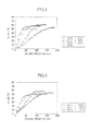
- Fig. 4 represents the relationship between poling conditions and d 33 in the polymer composite piezoelectric bodies as fabricated in this working example by using cyanoethylated PVA for a binder.
- Fig. 5 represents the relationship between poling conditions and d 33 in the polymer composite piezoelectric bodies as fabricated for comparison by using cyanoethylated pullulan for a binder. It is seen from Figs. 4 and 5 that the rise of d 33 with respect to the electric field was improved with the increase in temperature irrespective of whether cyanoethylated PVA or cyanoethylated pullulan was used for a binder.
- d 33 values at electric fields of 50 kV/cm and 100 kV/cm as shown in Fig. 4 are plotted.
- Fig. 7 the d 33 values at electric fields of 50 kV/cm and 100 kV/cm as shown in Fig. 5 are plotted.
- d 33 was improved at poling temperatures not lower than 40°C if cyanoethylated PVA was used.
- d 33 was high, that is to say, not lower than 55 pC/N in the temperature range of 100 to 120°C at an electric field of 50 kV/cm, and in the temperature range of 60 to 120°C at an electric field of 100 kV/cm.
- d 33 was improved at poling temperatures not lower than 100°C if cyanoethylated pullulan was used.
- the value of d 33 was not higher than 50 pC/N at any temperature in the case of an electric field of 50 kV/cm, and was only higher than 55 pC/N at a temperature of 120°C in the case of an electric field of 100 kV/cm.
- piezoelectric ceramics with a perovskite-type crystal structure typified by PZT
- PZT have no center of symmetry in the crystal structure and are polarized by the displacement of ions at temperatures lower than the Curie point. More considerable ion displacement will make a higher energy (field strength) required for poling, that is to say, make dielectric breakdown more liable to occur during poling. In addition, more considerable ion displacement will increase the deformation associated with poling, and cracks in ceramics, accordingly.
- a sample is heated to a temperature not higher than the Curie point so as to increase the symmetry of crystal and achieve thereby reduction in field strength required for poling and in deformation associated with poling.
- the poling temperature range in which d 33 got maximum varies between the case where cyanoethylated PVA was used for a binder and the case where cyanoethylated pullulan was used for a binder in spite of the fact that the piezoelectric ceramic particles as used were the same in both cases.
- each of the different binders cyanoethylated PVA and cyanoethylated pullulan
- an organic solvent composed of dimethylformamide (DMF) was dissolved in an organic solvent composed of dimethylformamide (DMF)
- the resultant solution was applied onto an aluminum substrate (300 ⁇ m in thickness) in an A4-sized coating area thereof (30 cm x 21 cm) so that the dried coating film might have a thickness of 30 ⁇ m, before DMF was evaporated by the drying by heating on a hot plate at 120°C.
- the relevant binder in the form of an A4-sized sheet with a thickness of 30 ⁇ m was thus formed on the aluminum substrate.
- each binder was divided into 20 mm-square pieces along with the aluminum substrate, and an upper electrode composed of aluminum and having a diameter of 15 mm and a thickness of 0.5 ⁇ m was formed on each binder piece by vacuum deposition.
- the different binders in sheet form which had been formed as described above were measured in dielectric constant by using an impedance analyzer (4294A manufactured by Agilent Corp.) in the temperature range of 20 to 120°C and at a frequency of 1 kHz.
- the binders were also measured in hardness by using a thermomechanical analyzer (TMA-60 manufactured by SHIMADZU CORPORATION) at a rate of temperature increase of 10°C/min. and with a load of 10g.
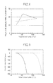
- Fig. 8 shows the temperature dependence of the relative dielectric constant in the different binders.
- the property of cyanoethylated PVA is represented by a solid curve while that of cyanoethylated pullulan is represented by a dotted curve.
- the dielectric constant of cyanoethylated PVA abruptly increased with the increase in temperature, got maximum at about 60°C, and then decreased again.
- the strength of electric field applied to a piezoelectric ceramic in a polymer binder increases as the binder has a higher dielectric constant, so that a temperature near 60°C is expected to be most suitable for poling if the dielectric constant is solely to be taken into account.
- d 33 began to increase at about 40°C and got maximum at about 100°C in the case of a field strength of 50 kV/cm.
- the dielectric constant of cyanoethylated pullulan increased concomitantly with the increase in temperature in an almost linear manner.
- d 33 did not change in the range of 20 to 100°C but began at last to increase at about 120°C in the case of a field strength of 50 kV/cm.
- Fig. 9 shows the temperature dependence of the penetration in the different binders.
- the property of cyanoethylated PVA is represented by a solid curve while that of cyanoethylated pullulan is represented by a dotted curve.
- the softening point of cyanoethylated PVA was about 30 to 40°C while that of cyanoethylated pullulan was about 100 to 120°C.
- the softening points of the binders as such are evidently consistent with the temperatures at which d 33 began to increase in the relationships between the poling temperature and d 33 ( Figs. 6 and 7 ) as described before.
- the poling of a piezoelectric ceramic physically means nothing but the orientation of polarization by the displacement of a 180° domain wall in each crystal grain. If the piezoelectric ceramic is being dispersed in a polymer matrix, as is the case with the polymer composite piezoelectric body of this working example, many of 180° domain walls are under constraint of a binder, so that it is necessary for the displacement of 180° domain walls to overcome the constraint of the binder. In addition, the displacement of 180° domain walls is known to involve the displacement of non-180° domain walls. Such displacement causes considerable deformation of ceramic particles and, accordingly, requires again that the resistance from the binder be overcome.
- the use of cyanoethylated PVA for a polymer matrix thus makes it possible to attain the method of manufacturing a polymer composite piezoelectric body that allows manufacture with high yields involving neither dielectric breakdown nor peeling off even for polymer composite piezoelectric bodies of large area, and the polymer composite piezoelectric body which is free from dielectric breakdown and peeling off even if large in area.
Landscapes
- Chemical & Material Sciences (AREA)
- Engineering & Computer Science (AREA)
- Chemical Kinetics & Catalysis (AREA)
- Medicinal Chemistry (AREA)
- Polymers & Plastics (AREA)
- Organic Chemistry (AREA)
- Health & Medical Sciences (AREA)
- Manufacturing & Machinery (AREA)
- Composite Materials (AREA)
- Materials Engineering (AREA)
- Physics & Mathematics (AREA)
- Spectroscopy & Molecular Physics (AREA)
- Compositions Of Macromolecular Compounds (AREA)
- Transducers For Ultrasonic Waves (AREA)
- Ultra Sonic Daignosis Equipment (AREA)
- Processes Of Treating Macromolecular Substances (AREA)
- Particle Formation And Scattering Control In Inkjet Printers (AREA)
Abstract
Description
- The present invention relates to polymer composite piezoelectric bodies suitable for piezoelectric devices, sensors, ultrasound probes, electric power generating devices, vibration-powered generators, and the like, as well as methods of manufacturing such piezoelectric bodies. The present invention is particularly directed to a polymer composite piezoelectric body having piezoelectric particles uniformly mixed by dispersion in a polymer matrix composed of cyanoethylated polyvinyl alcohol, and a method of manufacturing such a piezoelectric body.
- Polymeric piezoelectric materials are those piezoelectric materials which have characteristics inherent to polymer materials, such as good flexibility, high-impact properties, ease of machining, and ability to have an increased area, which are high in power output constant (piezoelectric "g" constant) as compared with inorganic piezoelectric materials, and which are similar in acoustic impedance to the human body or water, so that their application to various sensors, or ultrasonic transducers such as an ultrasound probe and a hydrophone, vibration controllers (dampers), or to the vibration energy harvesting is expected nowadays. In such fields of application, those piezoelectric materials are sought which have a piezoelectric strain constant ("d" constant) as an index to the strain amount per unit electric field (signal sending ability) and a "g" constant as an index to the strength of electric field generated per unit stress (signal receiving ability) both favorable in magnitude, or are excellent in balance between the constants.
- The polymeric piezoelectric materials are known to include piezoelectric polymers, namely, the polymers piezoelectric in themselves as typified by polyvinylidene fluoride (PVDF), which are low in "d" constant as compared with inorganic piezoelectric materials and, accordingly, cannot effect adequate performance if used for the above applications as a polymeric piezoelectric material.
- On the other hand, the polymer composite piezoelectric which is obtained by using a polymer material as a matrix and mixing an inorganic piezoelectric into the polymer matrix to produce a piezoelectric composite is a piezoelectric allowed to have the above advantages typical of polymer materials and an excellent piezoelectric performance ("d" constant) of the inorganic piezoelectric in an effective manner. Polymer composite piezoelectrics are claiming attention as a piezoelectric variable in material design with different applications by changing the type of a polymer serving as a matrix, the type or composition of the inorganic piezoelectric, the connectivity, or the shape, or the blending ratio. In consequence, a variety of polymer composite piezoelectrics have been proposed (see Patent Literature 1, for instance).
As a matter of course, it is preferable that a piezoelectric with high piezoelectric performance is used for a polymer composite piezoelectric, so that use is chiefly made of lead-based piezoelectric materials having extremely high "d" constants, such as lead zirconate titanate (Pb(Zr,Ti)O3: PZT). - Patent Literature 1 discloses the electronic component material having good dielectricity, pyroelectricity and piezoelectricity that is obtained by forming a composite product by uniformly mixing by dispersion a ferroelectric substance consisting of ceramic particles with a perovskite-type crystal structure in a dielectric binder composed of cyanoethylated cellulose and/or cyanoethylated pullulan, and applying a specified voltage to the composite product.
-
- Patent Literature 1:
JP 2007-157413 A - In the electronic component material as disclosed in Patent Literature 1, however, the composite product as a combination of cyanoethylated pullulan and piezoelectric particles that is formed on a substrate by casting is liable to undergo, during subsequent poling (polarization treatment) conducted thereon, dielectric breakdown at spots with low withstand voltages caused therein by an uneven thickness or nonuniform particle dispersion, which makes large-area production difficult. Moreover, cyanoethylated pullulan has a poor adhesion to other types of materials, and is liable to have troubles, such as cracking and peeling off, during the step of drying following the casting, which also makes large-area production difficult.
- An object of the present invention is to solve the above problems with the prior art so as to provide a method of manufacturing a polymer composite piezoelectric body, allowing manufacture with high yields involving neither dielectric breakdown nor peeling off even for polymer composite piezoelectric bodies of large area, and a polymer composite piezoelectric body manufactured by such a method.
- In order to achieve the above object, the present invention provides a polymer composite piezoelectric body obtained by conducting poling on a composite having piezoelectric particles uniformly mixed by dispersion in a polymer matrix comprising cyanoethylated polyvinyl alcohol (cyanoethylated PVA).
It should be noted that not only the composite having piezoelectric particles uniformly mixed by dispersion in a polymer matrix that is to be subjected to poling but the polymer composite piezoelectric body which is obtained by conducting polarization treatment (poling) on the composite may be referred to as "piezoelectric composite." - In the present invention, it is preferable that the polymer matrix is cyanoethylated polyvinyl alcohol to which is added at least one high-dielectric or ferroelectric polymer out of fluoropolymers, such as polyvinylidene fluoride, vinylidne fluoride - tetrafluoroethylene copolymer, vinylidene fluoride - trifluoroethylene copolymer, polyvinylidene fluoride - trifluoroethylene copolymer, and polyvinylidene fluoride - tetrafluoroethylene copolymer; or out of cyano group- or cyanoethyl group-containing polymers, such as vinylidene cyanate - vinyl acetate copolymer, cyanoethyl cellulose, cyanoethyl hydroxysaccharose, cyanoethyl hydroxycellulose, cyanoethyl hydroxypullulan, cyanoethyl methacrylate, cyanoethyl acrylate, cyanoethyl hydroxyethyl cellulose, cyanoethyl amylose, cyanoethyl hydroxypropyl cellulose, cyanoethyl dihydroxypropyl cellulose, cyanoethyl hydroxypropyl amylose, cyanoethyl polyacrylamide, cyanoethyl polyacrylate, cyanoethyl pullulan, cyanoethyl polyhydroxymethylene, cyanoethyl glycidol pullulan, cyanoethyl saccharose, and cyanoethyl sorbitol; or out of synthetic rubbers, such as nitrile rubber and chloroprene rubber.
- It is also preferable in the present invention that the piezoelectric particles comprise ceramic particles having a perovskite-type crystal structure. In that case, the ceramic particles are composed of, for instance, lead zirconate titanate, lead lanthanate zirconate titanate, barium titanate, or a solid solution of barium titanate and bismuth ferrite.
- The present invention also provides a method of manufacturing a polymer composite piezoelectric body, comprising the steps of: forming, on a substrate, a composite having piezoelectric particles uniformly mixed by dispersion in a polymer matrix comprising cyanoethylated polyvinyl alcohol; and conducting poling on the composite.
Preferably, the step of forming a composite includes casting a piezoelectric particle-containing coating solution onto the substrate, with the coating solution being obtained by dispersing the piezoelectric particles in an organic solvent in which a dielectric binder comprising the cyanoethylated polyvinyl alcohol has been dissolved; and then evaporating the organic solvent so as to form a coating film.
The substrate is preferably any of various metal sheets, or a polymer film provided on its at least one face with a coating/foil of metal, such as aluminum or copper, serving as a lower electrode. A composite product comprising an organic polymer and conductive particles may also be used for the substrate. In that case, the organic polymer is preferably composed of at least one out of a thermoplastic resin, a thermoplastic elastomer, and a vulcanized rubber. For the conductive particles, C, Pd, Fe, Sn, Al, Ni, Pt, Au, Ag, Cu, Cr, Mo, or an alloy thereof is used.
The method of casting the coating solution onto the substrate may be any of conventional solution casting methods including doctor coating and blade coating. A composite formed by a conventional casting method generally has a thickness of about 50 to 100 µm. - The step of conducting poling preferably includes providing an upper electrode on a surface of the composite that is opposite with a face in contact with the substrate, then heating the composite to a specified temperature, and applying a direct electric field between the substrate (lower electrode) and the upper electrode for a specified period of time.
It is also possible that the step of conducting poling includes the step of applying a specified direct electric field between the substrate (lower electrode) and a corona electrode in rod or wire form, which is positioned at a specified distance from a surface of the composite that is opposite with a face in contact with the substrate, and which is movable along the surface of the composite, while heating the composite to a specified temperature and keeping it at that temperature, so as to cause corona discharge; and, under the corona discharge, causing the corona electrode to move relatively to the composite along the surface of the composite.
The temperature to which the composite is to be heated during the poling is preferably 60 to 120°C. - It is preferable that the piezoelectric particles comprise ceramic particles having a perovskite-type crystal structure. In that case, the ceramic particles are composed of, for instance, lead zirconate titanate, lead lanthanate zirconate titanate, barium titanate, or a solid solution of barium titanate and bismuth ferrite.
The dielectric binder may be cyanoethylated polyvinyl alcohol to which is added at least one high-dielectric or ferroelectric polymer out of fluoropolymers, such as polyvinylidene fluoride, vinylidne fluoride - tetrafluoroethylene copolymer, vinylidene fluoride - trifluoroethylene copolymer, polyvinylidene fluoride - trifluoroethylene copolymer, and polyvinylidene fluoride - tetrafluoroethylene copolymer; or out of cyano group- or cyanoethyl group-containing polymers, such as vinylidene cyanate - vinyl acetate copolymer, cyanoethyl cellulose, cyanoethyl hydroxysaccharose, cyanoethyl hydroxycellulose, cyanoethyl hydroxypullulan, cyanoethyl methacrylate, cyanoethyl acrylate, cyanoethyl hydroxyethyl cellulose, cyanoethyl amylose, cyanoethyl hydroxypropyl cellulose, cyanoethyl dihydroxypropyl cellulose, cyanoethyl hydroxypropyl amylose, cyanoethyl polyacrylamide, cyanoethyl polyacrylate, cyanoethyl pullulan, cyanoethyl polyhydroxymethylene, cyanoethyl glycidol pullulan, cyanoethyl saccharose, and cyanoethyl sorbitol; or out of synthetic rubbers, such as nitrile rubber and chloroprene rubber. - According to the present invention in which cyanoethylated PVA having a softening temperature in the vicinity of room temperature is used for a polymer matrix, mechanical constraints on piezoelectric particles can be reduced at relatively low heating temperatures with no increase in leak current. In consequence, a field strength required for poling is significantly reduced, which makes it possible to suppress dielectric breakdown even if there are spots with low withstand voltages caused in a composite by an uneven thickness or nonuniform dispersion of piezoelectric particles. In addition, by using, as a binder, cyanoethylated PVA having a good adhesion to other types of materials, such troubles as cracking and peeling off are suppressed during the step of drying following the casting.
The use of cyanoethylated PVA for a polymer matrix thus makes it possible to attain the method of manufacturing a polymer composite piezoelectric body that allows manufacture with high yields involving neither dielectric breakdown nor peeling off even for polymer composite piezoelectric bodies of large area, and the polymer composite piezoelectric body which is free from dielectric breakdown and peeling off even if large in area. -
- [
Fig. 1 ]
Fig. 1 is a schematic diagram showing a polymer composite piezoelectric body as an embodiment of the present invention. - [
Fig. 2 ]
Fig. 2 is a schematic diagram illustrating an example of the poling method to be used for the manufacture of the polymer composite piezoelectric body as an embodiment of the present invention. - [
Fig. 3 ]
Fig. 3(a) is a schematic diagram illustrating another example of the poling method to be used for the manufacture of the polymer composite piezoelectric body as an embodiment of the present invention, andFig. 3(b) is a schematic perspective illustrating another example of the poling method. - [
Fig. 4 ]
Fig. 4 is a graph representing the relationship between poling conditions and d33 in the polymer composite piezoelectric bodies as fabricated by using cyanoethylated PVA for a dielectric binder. - [
Fig. 5 ]
Fig. 5 is a graph representing the relationship between poling conditions and d33 in the polymer composite piezoelectric bodies as fabricated by using cyanoethylated pullulan for a dielectric binder. - [
Fig. 6 ]
Fig. 6 is a graph representing the relationship between the poling temperature and d33 in the polymer composite piezoelectric bodies as fabricated by using cyanoethylated PVA for a dielectric binder. - [
Fig. 7 ]
Fig. 7 is a graph representing the relationship between the poling temperature and d33 in the polymer composite piezoelectric bodies as fabricated by using cyanoethylated pullulan for a dielectric binder. - [
Fig. 8 ]
Fig. 8 is a graph showing the temperature dependence of an electrical property (dielectric constant) of different binders. - [
Fig. 9 ]
Fig. 9 is a graph showing the temperature dependence of a mechanical property (hardness) of different binders. - In the following, the polymer composite piezoelectric body and the manufacturing method thereof according to the present invention are detailed based on a preferred embodiment shown in the accompanying drawings.
Fig. 1 is a schematic diagram showing a polymer composite piezoelectric body as an embodiment of the present invention. - A polymer composite piezoelectric body (piezoelectric composite) 10 shown in
Fig. 1 is obtained by conducting poling on a composite 16 havingpiezoelectric particles 14 of a ferroelectric material uniformly dispersed in apolymer matrix 12 composed of cyanoethylated polyvinyl alcohol (hereafter also referred to as "cyanoethylated PVA"). The polymer compositepiezoelectric body 10 includes alower electrode 20 and anupper electrode 22, with the former being provided on abottom face 16b, and the latter on atop face 16a, of the composite 16 for instance. - The
polymer matrix 12 is not limited to cyanoethylated PVA alone but may be the cyanoethylated PVA to which is added at least one high-dielectric or ferroelectric polymer out of fluoropolymers, such as polyvinylidene fluoride, vinylidne fluoride - tetrafluoroethylene copolymer, vinylidene fluoride - trifluoroethylene copolymer, polyvinylidene fluoride - trifluoroethylene copolymer, and polyvinylidene fluoride - tetrafluoroethylene copolymer; or out of cyano group- or cyanoethyl group-containing polymers, such as vinylidene cyanate - vinyl acetate copolymer, cyanoethyl cellulose, cyanoethyl hydroxysaccharose, cyanoethyl hydroxycellulose, cyanoethyl hydroxypullulan, cyanoethyl methacrylate, cyanoethyl acrylate, cyanoethyl hydroxyethyl cellulose, cyanoethyl amylose, cyanoethyl hydroxypropyl cellulose, cyanoethyl dihydroxypropyl cellulose, cyanoethyl hydroxypropyl amylose, cyanoethyl polyacrylamide, cyanoethyl polyacrylate, cyanoethyl pullulan, cyanoethyl polyhydroxymethylene, cyanoethyl glycidol pullulan, cyanoethyl saccharose, and cyanoethyl sorbitol; or out of synthetic rubbers, such as nitrile rubber and chloroprene rubber. - The
piezoelectric particles 14 are comprised of ceramic particles having a perovskite-type crystal structure. The ceramic particles which constitute thepiezoelectric particles 14 are composed of lead zirconate titanate (PZT), lead lanthanate zirconate titanate (PLZT), barium titanate (BaTiO3) or a solid solution (BFBT) of barium titanate and bismuth ferrite (BiFe3), for instance. - The polymer composite
piezoelectric body 10 is excellent in flexibility because thepolymer matrix 12 is used for it.
The polymer compositepiezoelectric body 10 may include a conductive or nonconductive substrate provided on at least one out of thetop face 16a and thebottom face 16b of the composite 16. The substrate is preferably flexible. - The manufacturing method of the polymer composite
piezoelectric body 10 is described in reference toFig. 2 .
Thelower electrode 20 of conductive nature is initially prepared. Thelower electrode 20 may also be a conductive film formed on another substrate (not shown) by sputtering or the like. - Then, the composite 16 is formed on a
surface 20a of thelower electrode 20.
In the method of forming the composite 16, a specified amount of thepiezoelectric particles 14 are dispersed uniformly in an organic solvent, such as methyl ethyl ketone, cyclohexanone or dimethylformamide (DMF), with a dielectric binder dissolved therein, which is composed of cyanoethylated PVA and adapted to serve as thepolymer matrix 12, so as to obtain a piezoelectric particle-containing coating solution, and the coating solution is cast onto thesurface 20a of thelower electrode 20, then the organic solvent is evaporated to form the composite 16.
The composite 16 may be formed by, apart from the method by casting as above, a method by extrusion using a melted dielectric binder with piezoelectric particles dispersed therein.
In this embodiment, the dielectric binder to be used is not limited to cyanoethylated PVA alone but may be the cyanoethylated PVA to which is added at least one high-dielectric or ferroelectric polymer out of fluoropolymers, such as polyvinylidene fluoride, vinylidne fluoride - tetrafluoroethylene copolymer, vinylidene fluoride - trifluoroethylene copolymer, polyvinylidene fluoride - trifluoroethylene copolymer, and polyvinylidene fluoride - tetrafluoroethylene copolymer; or out of cyano group- or cyanoethyl group-containing polymers, such as vinylidene cyanate - vinyl acetate copolymer, cyanoethyl cellulose, cyanoethyl hydroxysaccharose, cyanoethyl hydroxycellulose, cyanoethyl hydroxypullulan, cyanoethyl methacrylate, cyanoethyl acrylate, cyanoethyl hydroxyethyl cellulose, cyanoethyl amylose, cyanoethyl hydroxypropyl cellulose, cyanoethyl dihydroxypropyl cellulose, cyanoethyl hydroxypropyl amylose, cyanoethyl polyacrylamide, cyanoethyl polyacrylate, cyanoethyl pullulan, cyanoethyl polyhydroxymethylene, cyanoethyl glycidol pullulan, cyanoethyl saccharose, and cyanoethyl sorbitol; or out of synthetic rubbers, such as nitrile rubber and chloroprene rubber. - The
upper electrode 22 is then formed on thetop face 16a of the composite 16 by sputtering, for instance.
Thelower electrode 20 and theupper electrode 22 are connected with aDC power source 24. A heating means for heating the composite 16 and keeping it heated, such as a hot plate, is set so as to heat the composite 16 to a temperature of, for instance, 100°C. With the composite 16 being kept at the temperature, a DC electric field of several tens to several hundreds kV/cm, 50 kV/cm for instance, is applied between the lower andupper electrodes power source 24 for a specified period of time so as to carry out poling.
During the poling, a DC electric field is applied to thepiezoelectric particles 14 along the direction of the thickness of the composite 16, in which direction thelower electrode 20 and theupper electrode 22 are opposite to each other, so as to carry out poling and thereby obtain the polymer compositepiezoelectric body 10. - The
lower electrode 20 and theupper electrode 22 are so conductive as to allow a specified voltage to be applied to the composite 16 during poling, and may be composed of C, Pd, Fe, Sn, Al, Ni, Pt, Au, Ag, Cu, Cr, Mo, or an alloy thereof.
Thelower electrode 20 and theupper electrode 22 may be formed by vapor deposition, such as vacuum deposition and sputtering, or by printing, such as screen printing and inkjet printing. It is also possible to provide thelower electrode 20 and theupper electrode 22 in the form of foil composed of the above C, Pd, Fe, Sn, Al, Ni, Pt, Au, Ag, Cu, Cr, Mo, or alloy thereof.
Thelower electrode 20 and theupper electrode 22 may also be provided using a composite product composed of an organic polymer and conductive particles. In that case, the organic polymer to be used may be at least one out of a thermoplastic resin, a thermoplastic elastomer and a vulcanized rubber, and the conductive particles to be used may be particles of the above C, Pd, Fe, Sn, Al, Ni, Pt, Au, Ag, Cu, Cr, Mo, or alloy thereof. - In this embodiment, poling may be carried out as shown in
Figs. 3(a) and 3(b) . In that case, after the composite 16 is formed on thesurface 20a of thelower electrode 20, acorona electrode 26 in rod or wire form, which is movable along thetop face 16a of the composite 16, is provided above thetop face 16a of the composite 16 at a distance δ of up to several mm, 1 mm for instance, from thetop face 16a, as seen fromFigs. 3(a) and 3(b) . Thecorona electrode 26 and thelower electrode 20 are connected with theDC power source 24. In addition, a heating means for heating the composite 16 and keeping it heated, such as a hot plate, is prepared.
With the composite 16 being heated to and kept at a temperature of, for instance, 100°C, a DC voltage of several kV, 6 kV for instance, is applied between thelower electrode 20 and thecorona electrode 26 by thepower source 24 so as to generate corona discharge, and poling is carried out by moving thecorona electrode 26 located above thetop face 16a of the composite 16 along thetop face 16a. Hereafter, the poling utilizing corona discharge is also referred to as "corona poling treatment." - In order to move the
corona electrode 26, a known moving means can be used. The poling is not necessarily carried out by moving thecorona electrode 26 but may be carried out by providing a mechanism for moving the composite 16 so as to move the composite 16. Thus, the moving means for thecorona electrode 26 is not particularly limited as long as it allows thecorona electrode 26 to move relatively to the composite 16.
Depending on the configuration to which the polymer compositepiezoelectric body 10 is to be applied, thelower electrode 20 may be removed after the poling. On the other hand, thecorona electrode 26 is not limited in number to one, that is to say, may be two or more in number. - In the case where the
corona electrode 26 is used for poling as shown inFigs. 3(a) and 3(b) , a roll-to-roll method may be employed so as to conduct poling on the composite 16 transported in its longitudinal direction with a plurality ofcorona electrodes 26 provided in the transport path for the composite 16 so that they may be opposite to thetop face 16a of the composite. As a result, the polymer compositepiezoelectric body 10 can be manufactured with a large area. - The polymer composite piezoelectric body of this embodiment is usable as, for instance, various sensors including an ultrasonic sensor, a pressure sensor, a tactile sensor, and a strain sensor; acoustic devices such as a microphone, a pickup, and a speaker; ultrasonic transducers such as an ultrasound probe and a hydrophone; a vibration controller (damper) for use in vehicles, buildings, or sporting goods such as skis and rackets; or even as an electric power generating device. In the last case, the piezoelectric body of this embodiment is suitably used as a vibration-powered generator applied to a floor, a shoe, a tire, and the like.
- The configuration of the present invention is fundamentally as above. While the polymer composite piezoelectric body and the manufacturing method thereof according to the present invention have thus been detailed, the present invention is in no way limited to the embodiment as described above, and it is without saying that various improvements or modifications may be made without departing from the scope of the present invention.
- A detailed description is made below on the effects of the polymer composite piezoelectric body of the present invention.
In the following working example, polymer composite piezoelectric bodies were fabricated using cyanoethylated PVA for a dielectric binder, and measured in d33 under their respective poling conditions. In order to confirm the effects of the polymer composite piezoelectric body of the invention, polymer composite piezoelectric bodies for comparison were fabricated using cyanoethylated pullulan for a dielectric binder, and similarly measured in d33 under their respective poling conditions. - Samples were fabricated as follows: Initially, a piezoelectric particle-containing coating solution was prepared by adding PZT particles and cyanoethylated PVA (CR-V manufactured by Shin-Etsu Chemical Co., Ltd.) as a binder to an organic solvent composed of dimethylformamide (DMF) at the compositional ratio as below and dispersing them in the solvent using a propeller mixer (at a number of revolution of 2000 rpm).
- · PZT particles ......... 300 parts by weight
- · Cyanoethylated PVA ..... 30 parts by weight
- Then, the composite was divided into 20 mm-square pieces along with the aluminum substrate, and an upper electrode composed of aluminum and having a diameter of 15 mm and a thickness of 0.5 µm was formed on each composite piece by vacuum deposition.
Finally, poling was carried out by applying a specified DC electric field between the upper electrode and the aluminum substrate (lower electrode). Poling conditions were as follows. - · Temperature: 20 to 160°C
- · Field strength: 5 to 200 kV/cm
- · Time: 3 min.
- The polymer composite piezoelectric body samples as fabricated under their respective poling conditions were measured in piezoelectric constant d33 by using a d33 meter (PM300 manufactured by Piezotest Corp.) at a frequency of 110 Hz, a clamping force of 10 N, and a dynamic force of 0.25 N.
Fig. 4 represents the relationship between poling conditions and d33 in the polymer composite piezoelectric bodies as fabricated in this working example by using cyanoethylated PVA for a binder.Fig. 5 represents the relationship between poling conditions and d33 in the polymer composite piezoelectric bodies as fabricated for comparison by using cyanoethylated pullulan for a binder.
It is seen fromFigs. 4 and 5 that the rise of d33 with respect to the electric field was improved with the increase in temperature irrespective of whether cyanoethylated PVA or cyanoethylated pullulan was used for a binder. - In
Fig. 6 , the d33 values at electric fields of 50 kV/cm and 100 kV/cm as shown inFig. 4 are plotted. Similarly inFig. 7 , the d33 values at electric fields of 50 kV/cm and 100 kV/cm as shown inFig. 5 are plotted.
As seen fromFig. 6 , d33 was improved at poling temperatures not lower than 40°C if cyanoethylated PVA was used. The value of d33 was high, that is to say, not lower than 55 pC/N in the temperature range of 100 to 120°C at an electric field of 50 kV/cm, and in the temperature range of 60 to 120°C at an electric field of 100 kV/cm.
On the other hand, it is seen fromFig. 7 that d33 was improved at poling temperatures not lower than 100°C if cyanoethylated pullulan was used. The value of d33, however, was not higher than 50 pC/N at any temperature in the case of an electric field of 50 kV/cm, and was only higher than 55 pC/N at a temperature of 120°C in the case of an electric field of 100 kV/cm. - There was a tendency of d33 to decrease at a poling temperature higher than 120°C irrespective of whether cyanoethylated PVA or cyanoethylated pullulan was used as a binder. This is because the leak current during poling is increased at such a temperature so considerably that an adequate electric field is no longer applied to piezoelectric particles.
As described above, the use of cyanoethylated PVA for a binder makes it possible to reduce the temperature and the field strength during poling significantly from those in the case where cyanoethylated pullulan is used. The reason is discussed below. - Generally speaking, piezoelectric ceramics with a perovskite-type crystal structure, typified by PZT, have no center of symmetry in the crystal structure and are polarized by the displacement of ions at temperatures lower than the Curie point. More considerable ion displacement will make a higher energy (field strength) required for poling, that is to say, make dielectric breakdown more liable to occur during poling. In addition, more considerable ion displacement will increase the deformation associated with poling, and cracks in ceramics, accordingly. In a technique commonly used during the poling of a piezoelectric ceramic to cope with such problems, a sample is heated to a temperature not higher than the Curie point so as to increase the symmetry of crystal and achieve thereby reduction in field strength required for poling and in deformation associated with poling.
In this working example, the poling temperature range in which d33 got maximum varies between the case where cyanoethylated PVA was used for a binder and the case where cyanoethylated pullulan was used for a binder in spite of the fact that the piezoelectric ceramic particles as used were the same in both cases. This suggests that, if a polymer composite piezoelectric body composed of a polymer matrix and a piezoelectric ceramic is to be obtained by poling, one mechanism or another for reducing a field strength required for the poling functions as a result of the heating of a sample, apart from the increase of the symmetry of crystal of a piezoelectric ceramic as mentioned above.
Under the circumstances, the present inventors examined the temperature dependence of the electrical property (dielectric constant) and the mechanical property (hardness) each of which the different binders as used in this working example, cyanoethylated PVA and cyanoethylated pullulan, exhibited in themselves. Samples for the evaluation of electrical and mechanical properties were fabricated as follows. - Initially, each of the different binders, cyanoethylated PVA and cyanoethylated pullulan, was dissolved in an organic solvent composed of dimethylformamide (DMF), and the resultant solution was applied onto an aluminum substrate (300 µm in thickness) in an A4-sized coating area thereof (30 cm x 21 cm) so that the dried coating film might have a thickness of 30 µm, before DMF was evaporated by the drying by heating on a hot plate at 120°C. The relevant binder in the form of an A4-sized sheet with a thickness of 30 µm was thus formed on the aluminum substrate. Then, each binder was divided into 20 mm-square pieces along with the aluminum substrate, and an upper electrode composed of aluminum and having a diameter of 15 mm and a thickness of 0.5 µm was formed on each binder piece by vacuum deposition.
The different binders in sheet form which had been formed as described above were measured in dielectric constant by using an impedance analyzer (4294A manufactured by Agilent Corp.) in the temperature range of 20 to 120°C and at a frequency of 1 kHz. The binders were also measured in hardness by using a thermomechanical analyzer (TMA-60 manufactured by SHIMADZU CORPORATION) at a rate of temperature increase of 10°C/min. and with a load of 10g. -
Fig. 8 shows the temperature dependence of the relative dielectric constant in the different binders. InFig. 8 , the property of cyanoethylated PVA is represented by a solid curve while that of cyanoethylated pullulan is represented by a dotted curve. It is seen fromFig. 8 that the dielectric constant of cyanoethylated PVA abruptly increased with the increase in temperature, got maximum at about 60°C, and then decreased again. The strength of electric field applied to a piezoelectric ceramic in a polymer binder increases as the binder has a higher dielectric constant, so that a temperature near 60°C is expected to be most suitable for poling if the dielectric constant is solely to be taken into account. From the relationship between the poling temperature and d33 (Fig. 6 ), however, it is seen that d33 began to increase at about 40°C and got maximum at about 100°C in the case of a field strength of 50 kV/cm. The dielectric constant of cyanoethylated pullulan increased concomitantly with the increase in temperature in an almost linear manner. From the relationship between the poling temperature and d33 (Fig. 7 ), however, it is seen that d33 did not change in the range of 20 to 100°C but began at last to increase at about 120°C in the case of a field strength of 50 kV/cm. It is thus difficult to explain the reason why the poling temperature range in which d33 got maximum varies between the case where cyanoethylated PVA was used as a binder and the case where cyanoethylated pullulan was used as a binder, exclusively based on the dielectric constants of the binders. -
Fig. 9 shows the temperature dependence of the penetration in the different binders. InFig. 9 , the property of cyanoethylated PVA is represented by a solid curve while that of cyanoethylated pullulan is represented by a dotted curve. It is seen fromFig. 9 that the softening point of cyanoethylated PVA was about 30 to 40°C while that of cyanoethylated pullulan was about 100 to 120°C. The softening points of the binders as such are evidently consistent with the temperatures at which d33 began to increase in the relationships between the poling temperature and d33 (Figs. 6 and 7 ) as described before. In other words, the variation between the cases of cyanoethylated PVA and cyanoethylated pullulan having been used as a binder in the poling temperature range in which d33 got maximum is attributed to the difference in hardness between the binders, so that it is considered that a field strength required for poling can be reduced by heating a sample so as to soften the binder. - The poling of a piezoelectric ceramic physically means nothing but the orientation of polarization by the displacement of a 180° domain wall in each crystal grain. If the piezoelectric ceramic is being dispersed in a polymer matrix, as is the case with the polymer composite piezoelectric body of this working example, many of 180° domain walls are under constraint of a binder, so that it is necessary for the displacement of 180° domain walls to overcome the constraint of the binder. In addition, the displacement of 180° domain walls is known to involve the displacement of non-180° domain walls. Such displacement causes considerable deformation of ceramic particles and, accordingly, requires again that the resistance from the binder be overcome. In other words, since energy required for the displacement of 180° and non-180° domain walls in a polymer composite piezoelectric body is strongly influenced by the force of constraint exerted by a binder, the reduction in mechanical constraint on piezoelectric particles by heating a sample to a temperature not lower than the softening point of the binder is considered to be very effective at reducing a field strength required for poling.
- As a result of detailed investigations on the conditions for poling during the fabrication of a polymer composited piezoelectric body composed of a polymer matrix and a piezoelectric ceramic, the present inventors found that it is very effective at reducing a field strength required for poling to specify the poling temperature to be not lower than the softening temperature of a polymer binder, as described above. The finding is quite different from the conventional approach in which the symmetry of crystal of a piezoelectric ceramic is increased in order to reduce a field strength required for poling. Moreover, mechanical constraints on piezoelectric particles can be reduced at relatively low heating temperatures with no increase in leak current by using cyanoethylated PVA having a particularly low softening temperature among dielectric binders. In consequence, a field strength required for poling is significantly reduced, which makes it possible to suppress dielectric breakdown even if there are spots with low withstand voltages caused in a composite by an uneven thickness or nonuniform dispersion of piezoelectric particles. In addition, by using, as a binder, cyanoethylated PVA having a good adhesion to other types of materials, such troubles as cracking and peeling off are suppressed during the step of drying following the casting. In other words, the use of cyanoethylated PVA for a polymer matrix thus makes it possible to attain the method of manufacturing a polymer composite piezoelectric body that allows manufacture with high yields involving neither dielectric breakdown nor peeling off even for polymer composite piezoelectric bodies of large area, and the polymer composite piezoelectric body which is free from dielectric breakdown and peeling off even if large in area.
-
- 10: Polymer composite piezoelectric body
- 12: Polymer matrix
- 14: Piezoelectric particles
- 16: Composite
- 20: Lower electrode
- 22: Upper electrode
- 24: Power source
A slide coater was used to apply the piezoelectric particle-containing coating solution onto an aluminum substrate (300 µm in thickness) in an A4-sized coating area thereof (30 cm x 21 cm) so that the dried coating film might have a thickness of 70 µm, before DMF was evaporated by the drying by heating on a hot plate at 120°C. A composite in the form of an A4-sized coating with a thickness of 70 µm was thus formed on the aluminum substrate.
Claims (17)
- A polymer composite piezoelectric body having piezoelectric particles uniformly mixed by dispersion in a polymer matrix comprising cyanoethylated polyvinyl alcohol.
- A polymer composite piezoelectric body obtained by conducting polarization treatment on a composite having piezoelectric particles uniformly mixed by dispersion in a polymer matrix comprising cyanoethylated polyvinyl alcohol.
- The polymer composite piezoelectric body according to claim 1 or 2, wherein said polymer matrix is cyanoethylated polyvinyl alcohol with a dielectric binder added thereto.
- The polymer composite piezoelectric body according to claim 1 or 2, wherein said polymer matrix is cyanoethylated polyvinyl alcohol to which is added at least one high-dielectric or ferroelectric polymer out of fluoropolymers, namely, polyvinylidene fluoride, vinylidne fluoride - tetrafluoroethylene copolymer, vinylidene fluoride - trifluoroethylene copolymer, polyvinylidene fluoride - trifluoroethylene copolymer, and polyvinylidene fluoride - tetrafluoroethylene copolymer; or out of cyano group- or cyanoethyl group-containing polymers, namely, vinylidene cyanate - vinyl acetate copolymer, cyanoethyl cellulose, cyanoethyl hydroxysaccharose, cyanoethyl hydroxycellulose, cyanoethyl hydroxypullulan, cyanoethyl methacrylate, cyanoethyl acrylate, cyanoethyl hydroxyethyl cellulose, cyanoethyl amylose, cyanoethyl hydroxypropyl cellulose, cyanoethyl dihydroxypropyl cellulose, cyanoethyl hydroxypropyl amylose, cyanoethyl polyacrylamide, cyanoethyl polyacrylate, cyanoethyl pullulan, cyanoethyl polyhydroxymethylene, cyanoethyl glycidol pullulan, cyanoethyl saccharose, and cyanoethyl sorbitol; or out of synthetic rubbers, namely, nitrile rubber and chloroprene rubber.
- The polymer composite piezoelectric body according to any one of claims 1 through 4, wherein said piezoelectric particles comprise ceramic particles having a perovskite-type crystal structure.
- The polymer composite piezoelectric body according to claim 5, wherein said ceramic particles are composed of lead zirconate titanate, lead lanthanate zirconate titanate, barium titanate, or a solid solution of barium titanate and bismuth ferrite.
- A method of manufacturing a polymer composite piezoelectric body, comprising the steps of:forming, on a substrate, a composite having piezoelectric particles uniformly mixed by dispersion in a polymer matrix comprising cyanoethylated polyvinyl alcohol; andconducting polarization treatment on the composite.
- The method of manufacturing a polymer composite piezoelectric body according to claim 7, wherein said step of forming a composite includes the step of casting a piezoelectric particle-containing coating solution onto said substrate, with the coating solution being obtained by dispersing said piezoelectric particles in an organic solvent in which a dielectric binder comprising said cyanoethylated polyvinyl alcohol has been dissolved; and then evaporating the organic solvent so as to form a coating film.
- The method of manufacturing a polymer composite piezoelectric body according to claim 7 or 8, wherein said step of conducting polarization treatment includes providing an upper electrode on a surface of said composite that is opposite with a face in contact with said substrate, then heating the composite to a specified temperature, and applying a direct electric field between the substrate and the upper electrode for a specified period of time.
- The method of manufacturing a polymer composite piezoelectric body according to claim 7 or 8, wherein said step of conducting polarization treatment includes the step of applying a specified direct electric field between said substrate and a corona electrode in rod or wire form, which is positioned at a specified distance from a surface of said composite that is opposite with a face in contact with the substrate, and which is movable along the surface of the composite, while heating the composite to a specified temperature and keeping it at that temperature, so as to cause corona discharge; and, under the corona discharge, causing the corona electrode to move relatively to the composite along the surface of the composite.
- The method of manufacturing a polymer composite piezoelectric body according to any one of claims 7 through 10, wherein said piezoelectric particles comprise ceramic particles having a perovskite-type crystal structure.
- The method of manufacturing a polymer composite piezoelectric body according to any one of claims 7 through 11, wherein said dielectric binder is cyanoethylated polyvinyl alcohol to which is added at least one high-dielectric or ferroelectric polymer out of fluoropolymers, namely, polyvinylidene fluoride, vinylidne fluoride - tetrafluoroethylene copolymer, vinylidene fluoride - trifluoroethylene copolymer, polyvinylidene fluoride - trifluoroethylene copolymer, and polyvinylidene fluoride - tetrafluoroethylene copolymer; or out of cyano group- or cyanoethyl group-containing polymers, namely, vinylidene cyanate - vinyl acetate copolymer, cyanoethyl cellulose, cyanoethyl hydroxysaccharose, cyanoethyl hydroxycellulose, cyanoethyl hydroxypullulan, cyanoethyl methacrylate, cyanoethyl acrylate, cyanoethyl hydroxyethyl cellulose, cyanoethyl amylose, cyanoethyl hydroxypropyl cellulose, cyanoethyl dihydroxypropyl cellulose, cyanoethyl hydroxypropyl amylose, cyanoethyl polyacrylamide, cyanoethyl polyacrylate, cyanoethyl pullulan, cyanoethyl polyhydroxymethylene, cyanoethyl glycidol pullulan, cyanoethyl saccharose, and cyanoethyl sorbitol; or out of synthetic rubbers, namely, nitrile rubber and chloroprene rubber.
- The method of manufacturing a polymer composite piezoelectric body according to claim 9 or 10, wherein said composite is heated in said step of conducting polarization treatment to a temperature of 60 to 120°C.
- The method of manufacturing a polymer composite piezoelectric body according to any one of claims 7 through 13, wherein said substrate is a polymer film provided with a metal coating or metallic foil.
- The method of manufacturing a polymer composite piezoelectric body according to any one of claims 7 through 13, wherein said substrate is composed of a composite product comprising an organic polymer and conductive particles.
- The method of manufacturing a polymer composite piezoelectric body according to claim 15, wherein at least one out of a thermoplastic resin, a thermoplastic elastomer, and a vulcanized rubber is used for said organic polymer.
- The method of manufacturing a polymer composite piezoelectric body according to claim 15, wherein C, Pd, Fe, Sn, Al, Ni, Pt, Au, Ag, Cu, Cr, Mo, or an alloy thereof is used for said conductive particles.
Applications Claiming Priority (3)
| Application Number | Priority Date | Filing Date | Title |
|---|---|---|---|
| JP2010282068 | 2010-12-17 | ||
| JP2011153022A JP5588934B2 (en) | 2010-12-17 | 2011-07-11 | Polymer composite piezoelectric body and manufacturing method thereof |
| PCT/JP2011/077678 WO2012081403A1 (en) | 2010-12-17 | 2011-11-30 | Polymer composite piezoelectric body and method for producing same |
Publications (3)
| Publication Number | Publication Date |
|---|---|
| EP2654094A1 true EP2654094A1 (en) | 2013-10-23 |
| EP2654094A4 EP2654094A4 (en) | 2017-05-03 |
| EP2654094B1 EP2654094B1 (en) | 2020-07-29 |
Family
ID=46244512
Family Applications (1)
| Application Number | Title | Priority Date | Filing Date |
|---|---|---|---|
| EP11848696.8A Active EP2654094B1 (en) | 2010-12-17 | 2011-11-30 | Polymer composite piezoelectric body and method for producing same |
Country Status (6)
| Country | Link |
|---|---|
| US (1) | US8771541B2 (en) |
| EP (1) | EP2654094B1 (en) |
| JP (1) | JP5588934B2 (en) |
| KR (1) | KR101694579B1 (en) |
| CN (1) | CN103262275B (en) |
| WO (1) | WO2012081403A1 (en) |
Cited By (5)
| Publication number | Priority date | Publication date | Assignee | Title |
|---|---|---|---|---|
| FR3060857A1 (en) * | 2016-12-20 | 2018-06-22 | Compagnie Generale Des Etablissements Michelin | PIEZOELECTRIC COMPOSITES IN FLEXIBLE MATRIX |
| WO2019243750A1 (en) | 2018-06-21 | 2019-12-26 | Compagnie Generale Des Etablissements Michelin | Device consisting of an elastomer matrix, comprising piezoelectric charges and electrodes |
| EP3687769A4 (en) * | 2017-11-17 | 2021-06-16 | Hewlett-Packard Development Company, L.P. | THREE-DIMENSIONAL PRINTING |
| FR3105590A1 (en) | 2019-12-23 | 2021-06-25 | Compagnie Generale Des Etablissements Michelin | PIEZOELECTRIC COMPOSITE MATERIALS HAVING IMPROVED PIEZOELECTRIC PROPERTIES |
| FR3105589A1 (en) | 2019-12-23 | 2021-06-25 | Compagnie Generale Des Etablissements Michelin | PIEZOELECTRIC DEVICE WITH IMPROVED PIEZOELECTRIC PROPERTIES |
Families Citing this family (48)
| Publication number | Priority date | Publication date | Assignee | Title |
|---|---|---|---|---|
| JP5599856B2 (en) * | 2011-09-30 | 2014-10-01 | 富士フイルム株式会社 | Electroacoustic transducer and display device |
| JP6061374B2 (en) * | 2012-08-02 | 2017-01-18 | アルプス電気株式会社 | Method for manufacturing piezoelectric element |
| TWI484675B (en) * | 2012-12-20 | 2015-05-11 | Nat Univ Tsing Hua | Piezoelectric thin film with a complex nano-structure and touch sensor apparatus with the same |
| JP6221270B2 (en) * | 2013-03-11 | 2017-11-01 | 株式会社リコー | Electro-mechanical conversion element manufacturing apparatus and electro-mechanical conversion element manufacturing method |
| JP6344634B2 (en) * | 2013-03-15 | 2018-06-20 | 株式会社リコー | Droplet discharge head, droplet discharge apparatus, image forming apparatus, polarization processing method for electromechanical transducer, and method for manufacturing droplet discharge head |
| JP6132190B2 (en) * | 2013-03-15 | 2017-05-24 | 株式会社リコー | Droplet ejection head, liquid ejection device, image forming apparatus, polarization processing method for electromechanical transducer, and method for manufacturing droplet ejection head |
| JP6005093B2 (en) * | 2013-03-28 | 2016-10-12 | 富士フイルム株式会社 | Electroacoustic conversion film, electroacoustic transducer, flexible display and projector screen |
| JP5993772B2 (en) * | 2013-03-28 | 2016-09-14 | 富士フイルム株式会社 | Electroacoustic conversion film, flexible display, vocal cord microphone and instrument sensor |
| WO2014157684A1 (en) | 2013-03-29 | 2014-10-02 | 富士フイルム株式会社 | Speaker system |
| JP6005089B2 (en) | 2013-03-29 | 2016-10-12 | 富士フイルム株式会社 | Electroacoustic conversion film |
| JP6071932B2 (en) * | 2013-04-01 | 2017-02-01 | 富士フイルム株式会社 | Electroacoustic conversion film |
| KR101442632B1 (en) * | 2013-04-03 | 2014-09-22 | 한국세라믹기술원 | piezoelectric composite film and piezoelectric apparatus using the same |
| KR101465346B1 (en) * | 2013-06-27 | 2014-11-25 | 성균관대학교산학협력단 | Piezo-electric energy harvester including a compposite of piezo electric material and polymer |
| JP6099096B2 (en) * | 2013-09-04 | 2017-03-22 | アルプス電気株式会社 | Composite piezoelectric element |
| JP6255827B2 (en) * | 2013-09-17 | 2018-01-10 | 株式会社リコー | ELECTRO-MACHINE CONVERSION ELEMENT, DROPLET DISCHARGE HEAD, AND INKJET RECORDING DEVICE |
| KR101994736B1 (en) | 2014-07-16 | 2019-07-01 | 삼성전기주식회사 | Paste for electrostatic protection and their manufacturing method |
| KR101577961B1 (en) * | 2014-10-16 | 2015-12-16 | 한국세라믹기술원 | Piezo fiber composite structure |
| JP6275018B2 (en) * | 2014-11-25 | 2018-02-07 | 公益財団法人鉄道総合技術研究所 | Piezoelectric material and manufacturing method thereof, contact detection device, load detection device, and abnormal state detection device |
| TWI572262B (en) * | 2014-12-16 | 2017-02-21 | 國立清華大學 | Method for fabricating piezoelectric transducer |
| CN104638103A (en) * | 2015-02-04 | 2015-05-20 | 兰州大学 | Transparent film capable of generating electricity and preparing method |
| WO2016136591A1 (en) * | 2015-02-27 | 2016-09-01 | 富士フイルム株式会社 | Electroacoustic transducer and electroacoustic conversion system |
| JP6297204B2 (en) * | 2015-03-12 | 2018-03-20 | 富士フイルム株式会社 | Polymer composite piezoelectric material, electroacoustic conversion film, and electroacoustic transducer |
| KR101682912B1 (en) * | 2015-04-10 | 2016-12-06 | 한국세라믹기술원 | Manufacturing method of flexible piezoelectric device using ink-jet printing |
| JP6993555B2 (en) * | 2015-05-22 | 2022-01-13 | ダイキン工業株式会社 | Organic piezoelectric film |
| JP6373510B2 (en) | 2015-10-21 | 2018-08-15 | 富士フイルム株式会社 | Audiovisual system |
| KR102339058B1 (en) | 2016-03-11 | 2021-12-16 | 한국전자통신연구원 | Flexible piezoelectric composite and piezoelectric device including the same |
| US11529120B2 (en) | 2016-04-26 | 2022-12-20 | Koninklijke Philips N.V. | Ultrasound device contacting |
| CN109478592B (en) | 2016-06-23 | 2023-06-06 | 日本化学工业株式会社 | Filler for piezoelectric material, composite piezoelectric material, composite piezoelectric element, filler for composite piezoelectric material, and method for producing alkali metal niobate compound |
| WO2018135457A1 (en) * | 2017-01-17 | 2018-07-26 | 学校法人 関西大学 | Novel ferroelectric material |
| CN106893236A (en) * | 2017-03-01 | 2017-06-27 | 东北大学秦皇岛分校 | A kind of bismuth ferrite composite organic-inorganic material and preparation method thereof |
| US10636959B2 (en) | 2017-03-31 | 2020-04-28 | General Electric Company | Insitu corona poling of piezoelectric ceramics |
| WO2019135911A1 (en) * | 2018-01-08 | 2019-07-11 | Applied Materials, Inc. | Piezoelectric materials and devices and methods for preparing the same |
| WO2019180586A1 (en) * | 2018-03-20 | 2019-09-26 | Sabic Global Technologies B.V. | Flexible and low cost piezoelectric composites with high d33 values |
| CN108504012B (en) * | 2018-04-11 | 2020-06-30 | 中国科学院福建物质结构研究所 | Polyelectrolyte composite dielectric layer material and organic thin film transistor prepared from same |
| FR3082781B1 (en) * | 2018-06-21 | 2022-12-02 | Michelin & Cie | PNEUMATICS INCLUDING A PIEZOELECTRIC COMPOSITE |
| EP3890038A4 (en) * | 2018-11-28 | 2022-08-24 | Osaka Organic Chemical Industry Ltd. | PIEZOELECTRIC MATERIAL AND COMPOSITION OF PIEZOELECTRIC MATERIAL |
| CN110320519A (en) * | 2019-06-09 | 2019-10-11 | 重庆工商大学融智学院 | A kind of expression of spatial data and fast display method |
| WO2020261911A1 (en) * | 2019-06-28 | 2020-12-30 | 富士フイルム株式会社 | Polymer composite piezoelectric body, piezoelectric film, piezoelectric speaker, and flexible display |
| CN111048852A (en) * | 2019-12-13 | 2020-04-21 | 深圳先进技术研究院 | A lithium-ion battery ultrasonic guided wave monitoring device and method |
| CN111245081B (en) * | 2020-01-21 | 2023-06-20 | 电子科技大学 | Self-powered vehicle exhaust sensor and method |
| TWI751524B (en) * | 2020-04-10 | 2022-01-01 | 馗鼎奈米科技股份有限公司 | Method for electrically polarizing piezoelectric film |
| CN111662469B (en) * | 2020-04-23 | 2023-04-07 | 湖北大学 | Bismuth ferrite/polyvinylidene fluoride-trifluoroethylene multilayer composite film and preparation method thereof |
| CN112708228B (en) * | 2020-12-04 | 2022-09-27 | 南昌航空大学 | A kind of high energy storage performance ceramic/polymer dielectric composite material and preparation method thereof |
| US12144260B2 (en) * | 2021-01-21 | 2024-11-12 | Wisconsin Alumni Research Foundation | Wafer-scale piezoelectric bio-organic thin films |
| FR3128606A1 (en) * | 2021-10-22 | 2023-04-28 | Commissariat A L'energie Atomique Et Aux Energies Alternatives | PIEZOELECTRIC DEVICE WITH LOW POLARIZATION VOLTAGE |
| CN119278220A (en) * | 2022-06-30 | 2025-01-07 | 富士胶片株式会社 | Polymer, composite, composite piezoelectric, piezoelectric film, piezoelectric element |
| CN120019089A (en) * | 2023-04-06 | 2025-05-16 | 积水化学工业株式会社 | Polyvinyl alcohol resin, film roll and polyvinyl acetal resin |
| KR102829566B1 (en) * | 2023-10-17 | 2025-07-08 | 서울과학기술대학교 산학협력단 | Piezoelectric composites and piezoelectric sensors comprising the same |
Family Cites Families (8)
| Publication number | Priority date | Publication date | Assignee | Title |
|---|---|---|---|---|
| JPH07119406B2 (en) * | 1989-07-04 | 1995-12-20 | 日亜化学工業株式会社 | EL lamp |
| JPH05315072A (en) * | 1992-05-11 | 1993-11-26 | Nichia Chem Ind Ltd | EL element |
| JPH06267656A (en) * | 1993-03-15 | 1994-09-22 | Fuji Electric Co Ltd | Electroluminescence element |
| JP3252010B2 (en) * | 1993-04-05 | 2002-01-28 | 三菱化学株式会社 | Manufacturing method of polymer composite piezoelectric material |
| JP4572522B2 (en) * | 2003-07-31 | 2010-11-04 | Dic株式会社 | Epoxy resin composition, cured epoxy resin, and novolac resin |
| JP2007157413A (en) | 2005-12-02 | 2007-06-21 | Forestry & Forest Products Research Institute | Electronic component materials with good dielectric properties, pyroelectricity, and piezoelectricity |
| KR100903502B1 (en) * | 2006-07-19 | 2009-06-17 | 주식회사 엘지화학 | Electrode with organic/inorganic composite and battery comprising the same |
| JP7119406B2 (en) * | 2018-02-13 | 2022-08-17 | 大日本印刷株式会社 | Stretchable wiring board and manufacturing method thereof |
-
2011
- 2011-07-11 JP JP2011153022A patent/JP5588934B2/en active Active
- 2011-11-30 KR KR1020137015459A patent/KR101694579B1/en active Active
- 2011-11-30 CN CN201180060592.0A patent/CN103262275B/en active Active
- 2011-11-30 WO PCT/JP2011/077678 patent/WO2012081403A1/en not_active Ceased
- 2011-11-30 EP EP11848696.8A patent/EP2654094B1/en active Active
-
2013
- 2013-06-03 US US13/908,660 patent/US8771541B2/en active Active
Cited By (13)
| Publication number | Priority date | Publication date | Assignee | Title |
|---|---|---|---|---|
| WO2018115742A1 (en) | 2016-12-20 | 2018-06-28 | Compagnie Generale Des Etablissements Michelin | Piezoelectric composites comprising a flexible matrix |
| CN110199399A (en) * | 2016-12-20 | 2019-09-03 | 米其林集团总公司 | Piezo-electricity composite material including flexible substrate |
| FR3060857A1 (en) * | 2016-12-20 | 2018-06-22 | Compagnie Generale Des Etablissements Michelin | PIEZOELECTRIC COMPOSITES IN FLEXIBLE MATRIX |
| US11292189B2 (en) | 2017-11-17 | 2022-04-05 | Hewlett-Packard Development Company, L.P. | Three-dimensional printing |
| EP3687769A4 (en) * | 2017-11-17 | 2021-06-16 | Hewlett-Packard Development Company, L.P. | THREE-DIMENSIONAL PRINTING |
| WO2019243750A1 (en) | 2018-06-21 | 2019-12-26 | Compagnie Generale Des Etablissements Michelin | Device consisting of an elastomer matrix, comprising piezoelectric charges and electrodes |
| FR3083005A1 (en) | 2018-06-21 | 2019-12-27 | Compagnie Generale Des Etablissements Michelin | ELASTOMERIC MATRIX DEVICE COMPRISING PIEZOELECTRIC CHARGES AND ELECTRODES |
| FR3105590A1 (en) | 2019-12-23 | 2021-06-25 | Compagnie Generale Des Etablissements Michelin | PIEZOELECTRIC COMPOSITE MATERIALS HAVING IMPROVED PIEZOELECTRIC PROPERTIES |
| WO2021130434A1 (en) | 2019-12-23 | 2021-07-01 | Compagnie Generale Des Etablissements Michelin | Piezoelectric composite materials having improved piezoelectric properties |
| WO2021130435A1 (en) | 2019-12-23 | 2021-07-01 | Compagnie Generale Des Etablissements Michelin | Piezoelectric device having improved piezoelectric properties |
| FR3105589A1 (en) | 2019-12-23 | 2021-06-25 | Compagnie Generale Des Etablissements Michelin | PIEZOELECTRIC DEVICE WITH IMPROVED PIEZOELECTRIC PROPERTIES |
| US12550617B2 (en) | 2019-12-23 | 2026-02-10 | Compagnie Generale Des Etablissements Michelin | Piezoelectric composite materials having improved piezoelectric properties |
| US12563970B2 (en) | 2019-12-23 | 2026-02-24 | Compagnie Generales des Etablissements Michelin | Piezoelectric device having improved piezoelectric properties |
Also Published As
| Publication number | Publication date |
|---|---|
| JP5588934B2 (en) | 2014-09-10 |
| CN103262275A (en) | 2013-08-21 |
| JP2012142546A (en) | 2012-07-26 |
| WO2012081403A1 (en) | 2012-06-21 |
| EP2654094B1 (en) | 2020-07-29 |
| US8771541B2 (en) | 2014-07-08 |
| CN103262275B (en) | 2015-12-02 |
| KR20140009253A (en) | 2014-01-22 |
| US20130256581A1 (en) | 2013-10-03 |
| KR101694579B1 (en) | 2017-01-09 |
| EP2654094A4 (en) | 2017-05-03 |
Similar Documents
| Publication | Publication Date | Title |
|---|---|---|
| US8771541B2 (en) | Polymer composite piezoelectric body and manufacturing method for the same | |
| WO2013008781A1 (en) | Piezoelectric element | |
| JP6018108B2 (en) | Polymer composite piezoelectric material | |
| JP5859370B2 (en) | Energy conversion element and manufacturing method thereof | |
| JP5278038B2 (en) | Elastomer transducer | |
| EP0888643B1 (en) | Improved piezoelectric ceramic-polymer composites | |
| KR20160066938A (en) | Triboelectric generating device | |
| US20150322220A1 (en) | Ultrasonic transducer using ferroelectric polymer | |
| EP3937511A1 (en) | Electroacoustic transducer | |
| KR102695804B1 (en) | Method for manufacturing flexible laminated piezoelectric composites | |
| JP5931127B2 (en) | Piezoelectric ceramics, method for manufacturing the same, and piezoelectric ceramic speaker having the same | |
| EP2380220B1 (en) | Electromechanical materials and devices including the same | |
| Du et al. | The influence of processing parameters on piezoelectric and dielectric properties of dome-shaped composite PZT-epoxy actuators | |
| Almusallam et al. | Improving the dielectric and piezoelectric properties of screen-printed Low temperature PZT/polymer composite using cold isostatic pressing | |
| KR20160116603A (en) | Piezoelectric device using PVDF film bonded with azobenzene and manufacturing method thereof | |
| US12568766B2 (en) | Polymer-based piezoelectric composite material film | |
| JP7820812B2 (en) | Composite material for power generation and method for producing the same | |
| US20250221313A1 (en) | Apparatus, system and method for manufacturing piezoelectronics | |
| WO2023149075A1 (en) | Piezoelectric film | |
| JPH0462984A (en) | Manufacture of resin piezoelectric element | |
| CN114730828A (en) | Polymer composite piezoelectric body and method for producing raw material particles for composite body | |
| Arlt et al. | PZT/P (VDF-HFP) 0–3 composites: Preparation, electrical poling and piezoelectric properties |
Legal Events
| Date | Code | Title | Description |
|---|---|---|---|
| PUAI | Public reference made under article 153(3) epc to a published international application that has entered the european phase |
Free format text: ORIGINAL CODE: 0009012 |
|
| 17P | Request for examination filed |
Effective date: 20130606 |
|
| AK | Designated contracting states |
Kind code of ref document: A1 Designated state(s): AL AT BE BG CH CY CZ DE DK EE ES FI FR GB GR HR HU IE IS IT LI LT LU LV MC MK MT NL NO PL PT RO RS SE SI SK SM TR |
|
| DAX | Request for extension of the european patent (deleted) | ||
| RA4 | Supplementary search report drawn up and despatched (corrected) |
Effective date: 20170331 |
|
| RIC1 | Information provided on ipc code assigned before grant |
Ipc: H01L 41/08 20060101ALI20170327BHEP Ipc: H01L 41/45 20130101AFI20170327BHEP Ipc: C08L 29/04 20060101ALI20170327BHEP Ipc: H01L 41/37 20130101ALI20170327BHEP Ipc: H01L 41/18 20060101ALI20170327BHEP |
|
| STAA | Information on the status of an ep patent application or granted ep patent |
Free format text: STATUS: EXAMINATION IS IN PROGRESS |
|
| 17Q | First examination report despatched |
Effective date: 20170803 |
|
| REG | Reference to a national code |
Ref country code: DE Ref legal event code: R079 Ref document number: 602011068018 Country of ref document: DE Free format text: PREVIOUS MAIN CLASS: H01L0041260000 Ipc: H01L0041257000 |
|
| GRAP | Despatch of communication of intention to grant a patent |
Free format text: ORIGINAL CODE: EPIDOSNIGR1 |
|
| STAA | Information on the status of an ep patent application or granted ep patent |
Free format text: STATUS: GRANT OF PATENT IS INTENDED |
|
| RIC1 | Information provided on ipc code assigned before grant |
Ipc: H01L 41/18 20060101ALI20191009BHEP Ipc: H01L 41/37 20130101ALI20191009BHEP Ipc: C08L 29/04 20060101ALI20191009BHEP Ipc: H01L 41/257 20130101AFI20191009BHEP |
|
| INTG | Intention to grant announced |
Effective date: 20191031 |
|
| GRAJ | Information related to disapproval of communication of intention to grant by the applicant or resumption of examination proceedings by the epo deleted |
Free format text: ORIGINAL CODE: EPIDOSDIGR1 |
|
| STAA | Information on the status of an ep patent application or granted ep patent |
Free format text: STATUS: EXAMINATION IS IN PROGRESS |
|
| GRAP | Despatch of communication of intention to grant a patent |
Free format text: ORIGINAL CODE: EPIDOSNIGR1 |
|
| STAA | Information on the status of an ep patent application or granted ep patent |
Free format text: STATUS: GRANT OF PATENT IS INTENDED |
|
| INTC | Intention to grant announced (deleted) | ||
| GRAJ | Information related to disapproval of communication of intention to grant by the applicant or resumption of examination proceedings by the epo deleted |
Free format text: ORIGINAL CODE: EPIDOSDIGR1 |
|
| INTG | Intention to grant announced |
Effective date: 20200123 |
|
| GRAP | Despatch of communication of intention to grant a patent |
Free format text: ORIGINAL CODE: EPIDOSNIGR1 |
|
| INTG | Intention to grant announced |
Effective date: 20200221 |
|
| GRAS | Grant fee paid |
Free format text: ORIGINAL CODE: EPIDOSNIGR3 |
|
| GRAA | (expected) grant |
Free format text: ORIGINAL CODE: 0009210 |
|
| STAA | Information on the status of an ep patent application or granted ep patent |
Free format text: STATUS: THE PATENT HAS BEEN GRANTED |
|
| RAP1 | Party data changed (applicant data changed or rights of an application transferred) |
Owner name: FUJIFILM CORPORATION |
|
| AK | Designated contracting states |
Kind code of ref document: B1 Designated state(s): AL AT BE BG CH CY CZ DE DK EE ES FI FR GB GR HR HU IE IS IT LI LT LU LV MC MK MT NL NO PL PT RO RS SE SI SK SM TR |
|
| REG | Reference to a national code |
Ref country code: GB Ref legal event code: FG4D |
|
| REG | Reference to a national code |
Ref country code: CH Ref legal event code: EP |
|
| REG | Reference to a national code |
Ref country code: DE Ref legal event code: R096 Ref document number: 602011068018 Country of ref document: DE |
|
| REG | Reference to a national code |
Ref country code: AT Ref legal event code: REF Ref document number: 1296829 Country of ref document: AT Kind code of ref document: T Effective date: 20200815 |
|
| REG | Reference to a national code |
Ref country code: IE Ref legal event code: FG4D |
|
| REG | Reference to a national code |
Ref country code: LT Ref legal event code: MG4D |
|
| REG | Reference to a national code |
Ref country code: NL Ref legal event code: MP Effective date: 20200729 |
|
| REG | Reference to a national code |
Ref country code: AT Ref legal event code: MK05 Ref document number: 1296829 Country of ref document: AT Kind code of ref document: T Effective date: 20200729 |
|
| PG25 | Lapsed in a contracting state [announced via postgrant information from national office to epo] |
Ref country code: AT Free format text: LAPSE BECAUSE OF FAILURE TO SUBMIT A TRANSLATION OF THE DESCRIPTION OR TO PAY THE FEE WITHIN THE PRESCRIBED TIME-LIMIT Effective date: 20200729 Ref country code: HR Free format text: LAPSE BECAUSE OF FAILURE TO SUBMIT A TRANSLATION OF THE DESCRIPTION OR TO PAY THE FEE WITHIN THE PRESCRIBED TIME-LIMIT Effective date: 20200729 Ref country code: BG Free format text: LAPSE BECAUSE OF FAILURE TO SUBMIT A TRANSLATION OF THE DESCRIPTION OR TO PAY THE FEE WITHIN THE PRESCRIBED TIME-LIMIT Effective date: 20201029 Ref country code: SE Free format text: LAPSE BECAUSE OF FAILURE TO SUBMIT A TRANSLATION OF THE DESCRIPTION OR TO PAY THE FEE WITHIN THE PRESCRIBED TIME-LIMIT Effective date: 20200729 Ref country code: FI Free format text: LAPSE BECAUSE OF FAILURE TO SUBMIT A TRANSLATION OF THE DESCRIPTION OR TO PAY THE FEE WITHIN THE PRESCRIBED TIME-LIMIT Effective date: 20200729 Ref country code: NO Free format text: LAPSE BECAUSE OF FAILURE TO SUBMIT A TRANSLATION OF THE DESCRIPTION OR TO PAY THE FEE WITHIN THE PRESCRIBED TIME-LIMIT Effective date: 20201029 Ref country code: PT Free format text: LAPSE BECAUSE OF FAILURE TO SUBMIT A TRANSLATION OF THE DESCRIPTION OR TO PAY THE FEE WITHIN THE PRESCRIBED TIME-LIMIT Effective date: 20201130 Ref country code: ES Free format text: LAPSE BECAUSE OF FAILURE TO SUBMIT A TRANSLATION OF THE DESCRIPTION OR TO PAY THE FEE WITHIN THE PRESCRIBED TIME-LIMIT Effective date: 20200729 Ref country code: GR Free format text: LAPSE BECAUSE OF FAILURE TO SUBMIT A TRANSLATION OF THE DESCRIPTION OR TO PAY THE FEE WITHIN THE PRESCRIBED TIME-LIMIT Effective date: 20201030 Ref country code: LT Free format text: LAPSE BECAUSE OF FAILURE TO SUBMIT A TRANSLATION OF THE DESCRIPTION OR TO PAY THE FEE WITHIN THE PRESCRIBED TIME-LIMIT Effective date: 20200729 |
|
| PG25 | Lapsed in a contracting state [announced via postgrant information from national office to epo] |
Ref country code: LV Free format text: LAPSE BECAUSE OF FAILURE TO SUBMIT A TRANSLATION OF THE DESCRIPTION OR TO PAY THE FEE WITHIN THE PRESCRIBED TIME-LIMIT Effective date: 20200729 Ref country code: RS Free format text: LAPSE BECAUSE OF FAILURE TO SUBMIT A TRANSLATION OF THE DESCRIPTION OR TO PAY THE FEE WITHIN THE PRESCRIBED TIME-LIMIT Effective date: 20200729 Ref country code: PL Free format text: LAPSE BECAUSE OF FAILURE TO SUBMIT A TRANSLATION OF THE DESCRIPTION OR TO PAY THE FEE WITHIN THE PRESCRIBED TIME-LIMIT Effective date: 20200729 Ref country code: IS Free format text: LAPSE BECAUSE OF FAILURE TO SUBMIT A TRANSLATION OF THE DESCRIPTION OR TO PAY THE FEE WITHIN THE PRESCRIBED TIME-LIMIT Effective date: 20201129 |
|
| PG25 | Lapsed in a contracting state [announced via postgrant information from national office to epo] |
Ref country code: NL Free format text: LAPSE BECAUSE OF FAILURE TO SUBMIT A TRANSLATION OF THE DESCRIPTION OR TO PAY THE FEE WITHIN THE PRESCRIBED TIME-LIMIT Effective date: 20200729 |
|
| RAP4 | Party data changed (patent owner data changed or rights of a patent transferred) |
Owner name: FUJIFILM CORPORATION |
|
| PG25 | Lapsed in a contracting state [announced via postgrant information from national office to epo] |
Ref country code: IT Free format text: LAPSE BECAUSE OF FAILURE TO SUBMIT A TRANSLATION OF THE DESCRIPTION OR TO PAY THE FEE WITHIN THE PRESCRIBED TIME-LIMIT Effective date: 20200729 Ref country code: EE Free format text: LAPSE BECAUSE OF FAILURE TO SUBMIT A TRANSLATION OF THE DESCRIPTION OR TO PAY THE FEE WITHIN THE PRESCRIBED TIME-LIMIT Effective date: 20200729 Ref country code: DK Free format text: LAPSE BECAUSE OF FAILURE TO SUBMIT A TRANSLATION OF THE DESCRIPTION OR TO PAY THE FEE WITHIN THE PRESCRIBED TIME-LIMIT Effective date: 20200729 Ref country code: CZ Free format text: LAPSE BECAUSE OF FAILURE TO SUBMIT A TRANSLATION OF THE DESCRIPTION OR TO PAY THE FEE WITHIN THE PRESCRIBED TIME-LIMIT Effective date: 20200729 Ref country code: RO Free format text: LAPSE BECAUSE OF FAILURE TO SUBMIT A TRANSLATION OF THE DESCRIPTION OR TO PAY THE FEE WITHIN THE PRESCRIBED TIME-LIMIT Effective date: 20200729 Ref country code: SM Free format text: LAPSE BECAUSE OF FAILURE TO SUBMIT A TRANSLATION OF THE DESCRIPTION OR TO PAY THE FEE WITHIN THE PRESCRIBED TIME-LIMIT Effective date: 20200729 |
|
| REG | Reference to a national code |
Ref country code: DE Ref legal event code: R097 Ref document number: 602011068018 Country of ref document: DE |
|
| PG25 | Lapsed in a contracting state [announced via postgrant information from national office to epo] |
Ref country code: AL Free format text: LAPSE BECAUSE OF FAILURE TO SUBMIT A TRANSLATION OF THE DESCRIPTION OR TO PAY THE FEE WITHIN THE PRESCRIBED TIME-LIMIT Effective date: 20200729 |
|
| PLBE | No opposition filed within time limit |
Free format text: ORIGINAL CODE: 0009261 |
|
| STAA | Information on the status of an ep patent application or granted ep patent |
Free format text: STATUS: NO OPPOSITION FILED WITHIN TIME LIMIT |
|
| PG25 | Lapsed in a contracting state [announced via postgrant information from national office to epo] |
Ref country code: SK Free format text: LAPSE BECAUSE OF FAILURE TO SUBMIT A TRANSLATION OF THE DESCRIPTION OR TO PAY THE FEE WITHIN THE PRESCRIBED TIME-LIMIT Effective date: 20200729 Ref country code: MC Free format text: LAPSE BECAUSE OF FAILURE TO SUBMIT A TRANSLATION OF THE DESCRIPTION OR TO PAY THE FEE WITHIN THE PRESCRIBED TIME-LIMIT Effective date: 20200729 |
|
| REG | Reference to a national code |
Ref country code: CH Ref legal event code: PL |
|
| 26N | No opposition filed |
Effective date: 20210430 |
|
| PG25 | Lapsed in a contracting state [announced via postgrant information from national office to epo] |
Ref country code: LU Free format text: LAPSE BECAUSE OF NON-PAYMENT OF DUE FEES Effective date: 20201130 |
|
| REG | Reference to a national code |
Ref country code: BE Ref legal event code: MM Effective date: 20201130 |
|
| PG25 | Lapsed in a contracting state [announced via postgrant information from national office to epo] |
Ref country code: LI Free format text: LAPSE BECAUSE OF NON-PAYMENT OF DUE FEES Effective date: 20201130 Ref country code: SI Free format text: LAPSE BECAUSE OF FAILURE TO SUBMIT A TRANSLATION OF THE DESCRIPTION OR TO PAY THE FEE WITHIN THE PRESCRIBED TIME-LIMIT Effective date: 20200729 Ref country code: CH Free format text: LAPSE BECAUSE OF NON-PAYMENT OF DUE FEES Effective date: 20201130 |
|
| REG | Reference to a national code |
Ref country code: IE Ref legal event code: MM4A |
|
| PG25 | Lapsed in a contracting state [announced via postgrant information from national office to epo] |
Ref country code: IE Free format text: LAPSE BECAUSE OF NON-PAYMENT OF DUE FEES Effective date: 20201130 |
|
| PG25 | Lapsed in a contracting state [announced via postgrant information from national office to epo] |
Ref country code: TR Free format text: LAPSE BECAUSE OF FAILURE TO SUBMIT A TRANSLATION OF THE DESCRIPTION OR TO PAY THE FEE WITHIN THE PRESCRIBED TIME-LIMIT Effective date: 20200729 Ref country code: MT Free format text: LAPSE BECAUSE OF FAILURE TO SUBMIT A TRANSLATION OF THE DESCRIPTION OR TO PAY THE FEE WITHIN THE PRESCRIBED TIME-LIMIT Effective date: 20200729 Ref country code: CY Free format text: LAPSE BECAUSE OF FAILURE TO SUBMIT A TRANSLATION OF THE DESCRIPTION OR TO PAY THE FEE WITHIN THE PRESCRIBED TIME-LIMIT Effective date: 20200729 |
|
| PG25 | Lapsed in a contracting state [announced via postgrant information from national office to epo] |
Ref country code: MK Free format text: LAPSE BECAUSE OF FAILURE TO SUBMIT A TRANSLATION OF THE DESCRIPTION OR TO PAY THE FEE WITHIN THE PRESCRIBED TIME-LIMIT Effective date: 20200729 |
|
| PG25 | Lapsed in a contracting state [announced via postgrant information from national office to epo] |
Ref country code: BE Free format text: LAPSE BECAUSE OF NON-PAYMENT OF DUE FEES Effective date: 20201130 |
|
| REG | Reference to a national code |
Ref country code: DE Ref legal event code: R079 Ref document number: 602011068018 Country of ref document: DE Free format text: PREVIOUS MAIN CLASS: H01L0041257000 Ipc: H10N0030045000 |
|
| P01 | Opt-out of the competence of the unified patent court (upc) registered |
Effective date: 20230515 |
|
| PGFP | Annual fee paid to national office [announced via postgrant information from national office to epo] |
Ref country code: FR Payment date: 20250930 Year of fee payment: 15 |
|
| PGFP | Annual fee paid to national office [announced via postgrant information from national office to epo] |
Ref country code: DE Payment date: 20250930 Year of fee payment: 15 |
|
| PGFP | Annual fee paid to national office [announced via postgrant information from national office to epo] |
Ref country code: GB Payment date: 20251001 Year of fee payment: 15 |