EP2654020A1 - Method and system for determining the direction of the head of a person - Google Patents
Method and system for determining the direction of the head of a person Download PDFInfo
- Publication number
- EP2654020A1 EP2654020A1 EP13161540.3A EP13161540A EP2654020A1 EP 2654020 A1 EP2654020 A1 EP 2654020A1 EP 13161540 A EP13161540 A EP 13161540A EP 2654020 A1 EP2654020 A1 EP 2654020A1
- Authority
- EP
- European Patent Office
- Prior art keywords
- head
- deep data
- determining
- person
- image
- Prior art date
- Legal status (The legal status is an assumption and is not a legal conclusion. Google has not performed a legal analysis and makes no representation as to the accuracy of the status listed.)
- Granted
Links
Images
Classifications
-
- G—PHYSICS
- G06—COMPUTING OR CALCULATING; COUNTING
- G06T—IMAGE DATA PROCESSING OR GENERATION, IN GENERAL
- G06T7/00—Image analysis
- G06T7/20—Analysis of motion
-
- A—HUMAN NECESSITIES
- A61—MEDICAL OR VETERINARY SCIENCE; HYGIENE
- A61B—DIAGNOSIS; SURGERY; IDENTIFICATION
- A61B5/00—Measuring for diagnostic purposes; Identification of persons
- A61B5/103—Measuring devices for testing the shape, pattern, colour, size or movement of the body or parts thereof, for diagnostic purposes
- A61B5/11—Measuring movement of the entire body or parts thereof, e.g. head or hand tremor or mobility of a limb
-
- A—HUMAN NECESSITIES
- A61—MEDICAL OR VETERINARY SCIENCE; HYGIENE
- A61B—DIAGNOSIS; SURGERY; IDENTIFICATION
- A61B5/00—Measuring for diagnostic purposes; Identification of persons
- A61B5/16—Devices for psychotechnics; Testing reaction times ; Devices for evaluating the psychological state
- A61B5/18—Devices for psychotechnics; Testing reaction times ; Devices for evaluating the psychological state for vehicle drivers or machine operators
-
- G—PHYSICS
- G06—COMPUTING OR CALCULATING; COUNTING
- G06T—IMAGE DATA PROCESSING OR GENERATION, IN GENERAL
- G06T7/00—Image analysis
- G06T7/20—Analysis of motion
- G06T7/246—Analysis of motion using feature-based methods, e.g. the tracking of corners or segments
-
- G—PHYSICS
- G06—COMPUTING OR CALCULATING; COUNTING
- G06T—IMAGE DATA PROCESSING OR GENERATION, IN GENERAL
- G06T7/00—Image analysis
- G06T7/50—Depth or shape recovery
-
- G—PHYSICS
- G06—COMPUTING OR CALCULATING; COUNTING
- G06T—IMAGE DATA PROCESSING OR GENERATION, IN GENERAL
- G06T7/00—Image analysis
- G06T7/50—Depth or shape recovery
- G06T7/521—Depth or shape recovery from laser ranging, e.g. using interferometry; from the projection of structured light
-
- G—PHYSICS
- G06—COMPUTING OR CALCULATING; COUNTING
- G06T—IMAGE DATA PROCESSING OR GENERATION, IN GENERAL
- G06T7/00—Image analysis
- G06T7/70—Determining position or orientation of objects or cameras
- G06T7/73—Determining position or orientation of objects or cameras using feature-based methods
-
- G—PHYSICS
- G06—COMPUTING OR CALCULATING; COUNTING
- G06V—IMAGE OR VIDEO RECOGNITION OR UNDERSTANDING
- G06V20/00—Scenes; Scene-specific elements
- G06V20/50—Context or environment of the image
- G06V20/59—Context or environment of the image inside of a vehicle, e.g. relating to seat occupancy, driver state or inner lighting conditions
- G06V20/597—Recognising the driver's state or behaviour, e.g. attention or drowsiness
-
- G—PHYSICS
- G06—COMPUTING OR CALCULATING; COUNTING
- G06V—IMAGE OR VIDEO RECOGNITION OR UNDERSTANDING
- G06V40/00—Recognition of biometric, human-related or animal-related patterns in image or video data
- G06V40/10—Human or animal bodies, e.g. vehicle occupants or pedestrians; Body parts, e.g. hands
- G06V40/16—Human faces, e.g. facial parts, sketches or expressions
-
- G—PHYSICS
- G06—COMPUTING OR CALCULATING; COUNTING
- G06V—IMAGE OR VIDEO RECOGNITION OR UNDERSTANDING
- G06V40/00—Recognition of biometric, human-related or animal-related patterns in image or video data
- G06V40/10—Human or animal bodies, e.g. vehicle occupants or pedestrians; Body parts, e.g. hands
- G06V40/16—Human faces, e.g. facial parts, sketches or expressions
- G06V40/161—Detection; Localisation; Normalisation
- G06V40/162—Detection; Localisation; Normalisation using pixel segmentation or colour matching
-
- G—PHYSICS
- G06—COMPUTING OR CALCULATING; COUNTING
- G06T—IMAGE DATA PROCESSING OR GENERATION, IN GENERAL
- G06T2207/00—Indexing scheme for image analysis or image enhancement
- G06T2207/10—Image acquisition modality
- G06T2207/10028—Range image; Depth image; 3D point clouds
-
- G—PHYSICS
- G06—COMPUTING OR CALCULATING; COUNTING
- G06T—IMAGE DATA PROCESSING OR GENERATION, IN GENERAL
- G06T2207/00—Indexing scheme for image analysis or image enhancement
- G06T2207/20—Special algorithmic details
- G06T2207/20081—Training; Learning
-
- G—PHYSICS
- G06—COMPUTING OR CALCULATING; COUNTING
- G06T—IMAGE DATA PROCESSING OR GENERATION, IN GENERAL
- G06T2207/00—Indexing scheme for image analysis or image enhancement
- G06T2207/20—Special algorithmic details
- G06T2207/20084—Artificial neural networks [ANN]
-
- G—PHYSICS
- G06—COMPUTING OR CALCULATING; COUNTING
- G06T—IMAGE DATA PROCESSING OR GENERATION, IN GENERAL
- G06T2207/00—Indexing scheme for image analysis or image enhancement
- G06T2207/30—Subject of image; Context of image processing
- G06T2207/30196—Human being; Person
-
- G—PHYSICS
- G06—COMPUTING OR CALCULATING; COUNTING
- G06T—IMAGE DATA PROCESSING OR GENERATION, IN GENERAL
- G06T2207/00—Indexing scheme for image analysis or image enhancement
- G06T2207/30—Subject of image; Context of image processing
- G06T2207/30248—Vehicle exterior or interior
- G06T2207/30268—Vehicle interior
Definitions
- the invention concerns a method for determining the direction of the head of a person according to the preamble to claim 1.
- the invention also concerns a system for determining the direction of the head of a person according to the preamble to claim 9.
- the invention also concerns a motor vehicle.
- the invention further concerns a computer program and a computer program product.
- Inattention of vehicle driver is often a contributing factor in traffic accidents. Inattention of the driver can be traced to distraction in the form of cognitive distraction or visual distraction. Inattention of the driver can also be attributable to tiredness. Inattention on the part of the driver can be attributable to a combination of distraction and tiredness.
- a multitude of studies have been performed regarding the behavior of the driver in connection with inattention.
- One behavior that can be traced to inattention of the aforementioned type consists in that the driver turns his head to, for example, the left or right, e.g. due to driver distractions such as changing the heat setting, talking on the telephone, lifting and consuming food/snacks, movable objects etc.
- a number of systems for monitoring driver inattention are known.
- One means of detecting the head direction of a vehicle driver is to use a CCD camera that detects luminous intensity, wherein the camera detects the position and angle of the head of the driver, whereupon if the head of the driver is pointed in a given direction and an obstacle is detected, a warning system is activated.
- One problem with utilizing luminous intensity to determine the direction of the head is that the precision of the calculation of the direction of the head is limited.
- One object of the present invention is to provide a method for determining the direction of the head of a person, which method is of high precision and does not require specific information about the head shape.
- One object of the present invention is to provide a system for determining the direction of the head of a person, which method is of high precision and does not require specific information about the head shape.
- a method for determining the direction of the head of a person comprises the step of creating an image of said head comprising a desired view of the head, which method comprises the steps of: creating a deep data image of said head; extracting deep data from defined points on the deep data image of the head; and using said extracted deep data for assessing the direction of said head by utilizing a classification algorithm.
- Precise determinations of the direction of the head of a person are thereby enabled, wherein the determination can be made based on general cases and, consequently, directions can be determined for heads of highly various shapes.
- said deep data from said defined points contain more relevant information for determining the direction of the head than, for example, a slide, whereupon the precision and consequently the capacity for correct determination of the direction of the head of a person are significantly improved and can be applied to general cases without any specific information about the shape of the face, placement of the eyes, nose and/or mouth being required.
- said classification algorithm is improved continuously during a learning phase with regard to said determination, in that determinations are made, under feedback, for a number of different head shapes in order to adapt the determinative capacity of the algorithm to any head shape.
- the determination of the direction of the head by means of said deep data from defined points is thereby improved.
- said classification algorithm is based on characteristics of artificial neural networks.
- Using an artificial neural network enables effective improvement of said classification algorithm under said learning phase.
- said classification of the direction of the head comprises essentially straight ahead, turned to the right, turned to the left, turned upward and turned downward. Clear definitions of the head direction are thereby provided to facilitate said determination of the direction of the head.
- the method further comprises the step of determining the position of said head in the created deep data image.
- the creation of a deep data image of the head is thereby facilitated.
- the step of determining the position of said head in the created deep data image comprises the step of creating a two-dimensional head contour as the basis for said determination.
- the effective creation of a deep data image for effective extraction of deep data from defined points on the deep data image of the head is thereby enabled.
- said head belongs to a vehicle driver present in a vehicle driver compartment.
- determining the direction of the head of a vehicle driver enables effective determination of any inattention on the part of the driver that could affect the ability of the driver to operate the vehicle safety, whereupon measures can be taken to alert the driver to the prevailing risk.
- the inattention can, for example, be attributable to tiredness on the part of the driver.
- information about said direction of the head and changes therein is used to determine the presence of inattention on the part of said person.
- the information about inattention can thereby be used to alert the person so as to thus prevent a mistake from being made by the person, prevent an accident and/or improve the performance of the person.
- said deep data from said defined points contain more relevant information for determining the direction of the head than, for example, a slide, whereupon the precision and consequently the capacity to correctly determine the direction of the head of a person are significantly improved and can be applied to general cases without any specific information about the shape of the face, placement of the eyes, nose and/or mouth being required.
- said classification algorithm is arranged so as, during a learning phase, to continuously improve in terms of said determination in that determinations are made, under feedback, for a number of different head shapes in order to adapt the determinative capacity of the algorithm to any head shape.
- the determination of the direction of the head by means of said deep data from defined points is thereby improved.
- said classification algorithm is based on characteristics of artificial neural networks. Using an artificial neural network enables effective improvement of said classification algorithm during said learning phase.
- said classification of the direction of the head comprises essentially straight ahead, turned to the right, turned to the left, turned upward and turned downward. Clear definitions of head direction are thereby provided to facilitate said determination of the direction of the head.
- the system further comprises means for determining the position of said head in the created deep data image. The creation of a deep data image of the head is thereby facilitated.
- said means for determining said position of the head in the created deep data image comprise means for creating a two-dimensional head contour as a basis for said determination. Effective creation of a deep data image for effective extraction of deep data from defined points in the deep data image of the head is thereby enabled.
- said head belongs to a vehicle driver present in a vehicle driver compartment.
- determining the direction of the head of a vehicle driver enables effective determination of any inattention on the part of the driver that could affect the ability of the driver to operate the vehicle safely, whereupon measures can be taken to alert the driver to the prevailing risk.
- the inattention can be attributable to, for example, tiredness on the part of the driver.
- information about said direction of the head and changes therein is intended to be used to determine the presence of inattention on the part of said person.
- the information about inattention can thus be used to alert the person in order to thereby prevent a mistake from being made by the person, prevent an accident and/or improve the performance of the person.
- link refers herein to a communications link, which can be a physical line, such as an opto-electronic communication line, or a non-physical line, such as a wireless connection, for example a radio or microwave link.
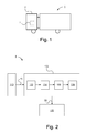
- Fig. 1 schematically illustrates a motor vehicle 1 according to one embodiment of the present invention.
- the exemplary vehicle 1 consists of a heavy vehicle in the form of a goods vehicle with a cab 2.
- the vehicle can alternatively consist of any suitable vehicle, such as a bus or a car.
- the vehicle contains a system I according to the present invention.
- Fig. 2 schematically illustrates a system I for determining the direction of the head of a person according to one embodiment of the present invention.
- the system I comprises an electronic control unit 100 or computer for said determination of the direction of the head a person.
- the system I further comprises means 110 for creating a deep data image.
- Said means 110 for creating a deep data image comprise a camera device 110 for deep data imaging.
- the camera device for deep data imaging consists of a 3D camera device, wherein the camera device according to one variant consists of a Kinect® from the Microsoft Corporation.
- said camera device 110 is arranged in a driver compartment such as a cab.
- the camera device 100 is herein arranged in the driver compartment to reproduce a deep data image of the head of the driver.
- the camera device 100 is herein pointed at the face of the driver.
- the camera device 110 is arranged at a distance from and obliquely above the driver.
- the system further comprises means 120 for utilizing information about the direction of the head.
- Said means 120 can comprise warning devices such as alarm devices, vibrator devices, blinking devices/lighting devices and/or activation devices to activate brake devices on the vehicle to alert the driver.
- Said warning devices can be dependent upon other information and activated when certain criteria are met, such as, when the system is disposed in a vehicle, an obstacle along the route of the vehicle or the like.
- Information about the direction of the head and changes therein is consequently, according to this variant, intended to be used to determine the presence of inattention on the part of the person and, by means of said means, to utilize the information to alert the person.
- the information about inattention can thereby be used to alert the person in order to thus prevent a mistake from being made by the person, prevent an accident, for example, during operation of a vehicle and/or improving the performance of the person.
- the electronic control unit 100 is signal-connected to said camera device 110 for deep data imaging via a link 10.
- the electronic control unit 100 is arranged via the link 10 so as to receive a signal from said camera device 110 representing deep data.
- the electronic control unit 100 comprises means 102 for preprocessing said deep data image.
- Said means 102 for preprocessing said deep data image comprise any suitable image-processing means.
- said means 102 for preprocessing said deep data image comprise low-pass filtering to reduce noise and to reduce detail in the deep data image. Reduction of detail in the deep data image is performed because only the shape and direction of the head are of interest.
- said means 102 for preprocessing said deep data image comprise means for creating a contour image of the head comprising an edge detector.
- a so-called Canny edge detector which is a previously known algorithm, is used, wherein an image is taken as described with a single value for each pixel, e.g. a gray-scale value or deep value, as input data and performs a number of steps in accordance with the algorithm for producing the contour image.
- the electronic control unit 100 comprises means 104 for determining said head position in the created deep data image.
- Said means 104 for determining said head position in the created deep data image include means for creating a two-dimensional head contour as a basis for said determination.
- Said means 104 for determining said head position in the created deep data image according to one variant include so-called chamfer matching, which is a previously known algorithm wherein the contour image is utilized to match a binary template to the image.
- a distance map of the aforesaid created contour image is created, wherein said distance map of the contour image is used to find the position in which the distance for the binary template is minimized.
- a generic head template is created wherein the matching of the head template is achieved according to one variant by studying how well it matches a selection of a number of different head images of a number of persons, where the persons are looking in different directions in different head images.
- the performance of the generic head template is intended to be independent of the direction of the head of the person.
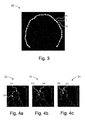
- Fig. 3 shows an example of a generic head template.
- the electronic control unit 100 comprises means 106 for extracting deep data from defined points on the deep data image of the head.
- deep data can be extracted from the deep data image.
- said defined points consist of a set of points distributed according to a predetermined pattern.
- said deep data points DP are divided into three rows, wherein the bottom row is somewhat displaced to the right relative to the overlying rows.
- each row has five points, and the total number of points is consequently fifteen.
- the number of points can be any suitable number, and the distribution of the points can be any suitable distribution.
- the coordinates of these rows are calculated based on the known positions for the determined head template.
- the electronic control unit 100 comprises means 108 for using said extracted deep data for determining said direction of the head by utilizing a classification algorithm.
- the fact that said predetermined points of deep data contain information about the head direction is thereby utilized.
- Said classification algorithm is utilized to find out how said deep data correlate with various directions of the head of a person.
- Said classification algorithm is based on characteristics of means for identifying linear relationships between input data in the form of a head shape of a person and output data in the form of various directions of the head of the person, wherein said output data according to one embodiment are classified in that: the person is looking to the left, the person is looking forward, the person is looking to the right.
- Said output data can be classified as any suitable direction of the head of the person, including that the person is looking to the left, the person is looking forward, the person is looking to the right, the person is looking upward, the person is looking downward, the person is looking rearward.
- Said output data can further be classified by a continuous distribution of the head direction, i.e. a continuous distribution of various angles of the head comprising to the left, straight ahead, to the right, rearward and angles therebetween, and/or upward, straight ahead and downward and angles therebetween.
- Said classification algorithm is consequently, according to one embodiment, configured so as to identify any distribution of the direction of the head, i.e. to identify the head turned straight forward and any arbitrary angle of the head relative to the head turned straight forward, including the head turned straight forward, the head turned to the: left, right upward, downward, rearward and angles therebetween.
- said classification algorithm is based on characteristics of artificial neural networks. According to alternative embodiments, said classification algorithm is based on characteristics of a so-called support vector machine, AdaBoost or Bayesian network.
- Said classification algorithm is, during a learning phase, arranged so as to be improved continuously in terms of said determination by making, under feedback, determinations for a number of different head shapes in order to adapt the determinative capacity of the algorithm to any head shape.
- Said input data [are] in the form of head shapes, wherein the shapes during learning consist of head shapes that have essentially different shapes. Furthermore, according to one variant an additional head shape is used for validation.
- the artificial neural network is designed to optimize the generalization of the relationship between input data in the form of head shapes and output data in the form of the direction of the head.
- Two hidden layers, a first hidden layer and a second hidden layer are a sufficient number of hidden layers, as any continuous or discrete function can be stored in two hidden layers, given that they are sufficiently large.
- the variables that are taken into account in designing the network are the number of neurons in the first hidden layer, the number of neurons in the second hidden layer, the learning speed ⁇ and an amount of motion ⁇ .
- the electronic control unit 100 is consequently arranged so as, based on said extracted deep data, to determine said direction of the head by utilizing a classification algorithm.
- the electronic control unit 100 is signal-connected to said means 120 for utilizing information about the direction of the head via a link 20.
- the electronic control unit 100 is arranged via the link 20 so as to transmit a signal to said means 120 for utilizing information about the direction of the head representing head direction data from said determined direction of the head for utilizing information about the direction of the head, wherein activation occurs according to the foregoing based on said information, i.e. based on the direction of the head, and on any other information, to alert the person to any inattention.
- Fig. 3 schematically illustrates one embodiment of a generic head template HT for optimizing the matching of various head shapes of persons the directions of whose heads are to be determined.
- the head template HT according to this embodiment comprises a number of distinct points P1, P2, whereupon an algorithm is configured to draw lines L between proximate points P1, P2. Each point is described by an x-coordinate and a y-coordinate.
- the head template comprises 42 distinct points.
- the head template HT can have any suitable number of distinct points.
- Figs. 4a-c schematically illustrate deep data images D1, D2, D3 of various persons who are looking in various directions, i.e. various directions of the head H1, H2, H3 of various persons with different head shapes, with defined points DP from which deep data are extracted.
- the persons according to Figs. 4a-c are filtered deep data images D1, D2, D3 of drivers sitting in a driver compartment in a vehicle.
- the distribution of said points DP from which deep data are extracted therein is three rows of five points, wherein the rows are somewhat mutually displaced so that underlying rows of points are displaced to the right relative to an overlying row of points. This is, as noted, just one example.
- the points can be arbitrary in number, and distributed in an arbitrary manner.
- Fig. 4a shows a driver who is looking to the left
- Fig. 4b shows a driver who is looking straight ahead
- Fig. 4c shows a driver who is looking to the right.
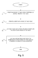
- Fig. 5 schematically illustrates a block diagram of a method for determining the direction of the head of a person according to one embodiment of the present invention.
- the method for determining the direction of the head of a person comprises a first step S1.
- an image of said head is created comprising a desired view of the head.
- the method for determining the direction of the head of a person comprises a second step S2. In this step, a deep data image of said head is created.
- the method for determining the direction of the head of a person comprises a third step S3.
- deep data are extracted from defined points on the deep data image of the head.
- the method for determining the direction of the head of a person comprises a fourth step S4.
- said extracted deep data are used to determine said direction of the head by utilizing a classification algorithm.
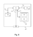
- the control unit 100 which is described with reference to fig. 2 , can, in one embodiment, include the apparatus 500.
- the apparatus 500 comprises a non-volatile memory 520, a data-processing unit 510 and a read/write memory 550.
- the non-volatile memory 520 has a first memory section 530 in which a computer program, such as an operating system, is stored to control the function of the apparatus 500.
- the apparatus 500 further comprises a bus controller, a serial communication port, I/O devices, an A/D converter, the time and date input and transfer unit, an event counter and a termination controller (not shown).
- the non-volatile memory 520 also has a second memory section 540.
- a computer program P contains routines for determining the direction of the head of a person according to the innovative method.
- the program P contains routines for creating an image of said head comprising a desired view of the head.
- the program P contains routines for creating a deep data image of said head.
- the program P contains routines for extracting deep data from defined points on the deep data image of the head.
- the program P contains routines for using said extracted deep data for determining said direction of the head by utilizing a classification algorithm.
- the program P can be stored in an executable form or in a compressed form in a memory 560 and/or in a read/write memory 550.
- the data-processing unit 510 executes a certain part of the program that is stored in the memory 560, or a certain part of the program that is stored in the read/write memory 550.
- the data-processing device 510 can communicate with a data port 599 via a data bus 515.
- the non-volatile memory 520 is intended to communicate with the data-processing unit 510 via a data bus 512.
- the separate memory 560 is intended to communicate with the data-processing unit 510 via a data bus 511.
- the read/write memory 550 is arranged so as to communicate with the data-processing unit 510 via a data bus 514. For example, the links associated with the control unit 100 can be connected to the data port 599.
- the data-processing unit 510 is arranged so as to execute code in a manner as described above.
- the signals received at the data port 599 can be used by the apparatus 500 to create an image of said head comprising a desired view of the head.
- the signals received at the data port 599 can be used by the apparatus 500 to create a deep data image of said head; extract deep data from defined points on the deep data image of the head.
- the signals received at the data port 599 can be used by the apparatus 500 to extract deep data from defined points on the deep data image of the head.
- the signals received at the data port 599 can be used by the apparatus 500 to use said extracted deep data for determining said direction of the head by utilizing a classification algorithm.
- Parts of the methods described herein can be performed by the apparatus 500 with the help of the data-processing unit 510, which runs the program stored in the memory 560 or the read/write memory 550.
- the apparatus 500 runs the program, the methods described herein are executed.
Landscapes
- Engineering & Computer Science (AREA)
- Physics & Mathematics (AREA)
- General Physics & Mathematics (AREA)
- Theoretical Computer Science (AREA)
- Health & Medical Sciences (AREA)
- Multimedia (AREA)
- Computer Vision & Pattern Recognition (AREA)
- Life Sciences & Earth Sciences (AREA)
- General Health & Medical Sciences (AREA)
- Oral & Maxillofacial Surgery (AREA)
- Human Computer Interaction (AREA)
- Public Health (AREA)
- Veterinary Medicine (AREA)
- Biophysics (AREA)
- Pathology (AREA)
- Biomedical Technology (AREA)
- Heart & Thoracic Surgery (AREA)
- Medical Informatics (AREA)
- Molecular Biology (AREA)
- Surgery (AREA)
- Animal Behavior & Ethology (AREA)
- Physiology (AREA)
- Dentistry (AREA)
- Child & Adolescent Psychology (AREA)
- Developmental Disabilities (AREA)
- Educational Technology (AREA)
- Hospice & Palliative Care (AREA)
- Psychiatry (AREA)
- Psychology (AREA)
- Social Psychology (AREA)
- Optics & Photonics (AREA)
- Image Analysis (AREA)
- Measurement Of The Respiration, Hearing Ability, Form, And Blood Characteristics Of Living Organisms (AREA)
- Image Processing (AREA)
Abstract
Description
- The invention concerns a method for determining the direction of the head of a person according to the preamble to claim 1. The invention also concerns a system for determining the direction of the head of a person according to the preamble to claim 9. The invention also concerns a motor vehicle. The invention further concerns a computer program and a computer program product.
- Inattention of vehicle driver is often a contributing factor in traffic accidents. Inattention of the driver can be traced to distraction in the form of cognitive distraction or visual distraction. Inattention of the driver can also be attributable to tiredness. Inattention on the part of the driver can be attributable to a combination of distraction and tiredness. A multitude of studies have been performed regarding the behavior of the driver in connection with inattention. One behavior that can be traced to inattention of the aforementioned type consists in that the driver turns his head to, for example, the left or right, e.g. due to driver distractions such as changing the heat setting, talking on the telephone, lifting and consuming food/snacks, movable objects etc.
- A number of systems for monitoring driver inattention are known. One means of detecting the head direction of a vehicle driver is to use a CCD camera that detects luminous intensity, wherein the camera detects the position and angle of the head of the driver, whereupon if the head of the driver is pointed in a given direction and an obstacle is detected, a warning system is activated.
- Other systems for monitoring driver inattention are known in which the detection of an eye direction for assessing inattention is achieved through the utilization of a plurality of cameras and IR technology.
- One problem with utilizing luminous intensity to determine the direction of the head is that the precision of the calculation of the direction of the head is limited.
- One object of the present invention is to provide a method for determining the direction of the head of a person, which method is of high precision and does not require specific information about the head shape.
- One object of the present invention is to provide a system for determining the direction of the head of a person, which method is of high precision and does not require specific information about the head shape.
- These and the other objects, which are presented in the description below, are achieved by means of a method, a system, a motor vehicle, a computer program and a computer program product of the kind specified above, and which further exhibits the features specified in the characterizing portion of attached
independent claims 1, 9, 17, 18 and 19. Preferred embodiments of the method and the system are described in attached non-independent claims 2-8 and 10-16. - According to the invention, these objects are achieved by a method for determining the direction of the head of a person, which method comprises the step of creating an image of said head comprising a desired view of the head, which method comprises the steps of: creating a deep data image of said head; extracting deep data from defined points on the deep data image of the head; and using said extracted deep data for assessing the direction of said head by utilizing a classification algorithm. Precise determinations of the direction of the head of a person are thereby enabled, wherein the determination can be made based on general cases and, consequently, directions can be determined for heads of highly various shapes. This is made possible in part because said deep data from said defined points contain more relevant information for determining the direction of the head than, for example, a slide, whereupon the precision and consequently the capacity for correct determination of the direction of the head of a person are significantly improved and can be applied to general cases without any specific information about the shape of the face, placement of the eyes, nose and/or mouth being required.
- According to one embodiment of the method, said classification algorithm is improved continuously during a learning phase with regard to said determination, in that determinations are made, under feedback, for a number of different head shapes in order to adapt the determinative capacity of the algorithm to any head shape. The determination of the direction of the head by means of said deep data from defined points is thereby improved.
- According to one embodiment of the method, said classification algorithm is based on characteristics of artificial neural networks. Using an artificial neural network enables effective improvement of said classification algorithm under said learning phase.
- According to one embodiment of the method, said classification of the direction of the head comprises essentially straight ahead, turned to the right, turned to the left, turned upward and turned downward. Clear definitions of the head direction are thereby provided to facilitate said determination of the direction of the head.
- According to one embodiment, the method further comprises the step of determining the position of said head in the created deep data image. The creation of a deep data image of the head is thereby facilitated.
- According to one embodiment of the method, the step of determining the position of said head in the created deep data image comprises the step of creating a two-dimensional head contour as the basis for said determination. The effective creation of a deep data image for effective extraction of deep data from defined points on the deep data image of the head is thereby enabled.
- According to one embodiment of the method, said head belongs to a vehicle driver present in a vehicle driver compartment. Thus determining the direction of the head of a vehicle driver enables effective determination of any inattention on the part of the driver that could affect the ability of the driver to operate the vehicle safety, whereupon measures can be taken to alert the driver to the prevailing risk. The inattention can, for example, be attributable to tiredness on the part of the driver.
- According to one embodiment of the method, information about said direction of the head and changes therein is used to determine the presence of inattention on the part of said person. The information about inattention can thereby be used to alert the person so as to thus prevent a mistake from being made by the person, prevent an accident and/or improve the performance of the person.
- According to the invention, these objects are achieved by a system for determining the direction of the head of a person, which system comprises means for creating an image of said head comprising a desired view of the head, comprising means for creating a deep data image of said head; means for extracting deep data from defined points on the deep data image of the head; means for using said extracted deep data to determine the direction of said head via the utilization of a classification algorithm. Precise determinations of the direction of the head of a person are thereby enabled, whereupon the determination can be made based on general cases and, consequently, the directions of heads with extremely various head shapes can be determined. This is made possible in part in that said deep data from said defined points contain more relevant information for determining the direction of the head than, for example, a slide, whereupon the precision and consequently the capacity to correctly determine the direction of the head of a person are significantly improved and can be applied to general cases without any specific information about the shape of the face, placement of the eyes, nose and/or mouth being required.
- According to one embodiment of the system, said classification algorithm is arranged so as, during a learning phase, to continuously improve in terms of said determination in that determinations are made, under feedback, for a number of different head shapes in order to adapt the determinative capacity of the algorithm to any head shape. The determination of the direction of the head by means of said deep data from defined points is thereby improved.
- According to one embodiment of the system, said classification algorithm is based on characteristics of artificial neural networks. Using an artificial neural network enables effective improvement of said classification algorithm during said learning phase.
- According to one embodiment of the system, said classification of the direction of the head comprises essentially straight ahead, turned to the right, turned to the left, turned upward and turned downward. Clear definitions of head direction are thereby provided to facilitate said determination of the direction of the head.
- According to one embodiment, the system further comprises means for determining the position of said head in the created deep data image. The creation of a deep data image of the head is thereby facilitated.
- According to one embodiment of the system, said means for determining said position of the head in the created deep data image comprise means for creating a two-dimensional head contour as a basis for said determination. Effective creation of a deep data image for effective extraction of deep data from defined points in the deep data image of the head is thereby enabled.
- According to one embodiment of the system, said head belongs to a vehicle driver present in a vehicle driver compartment. Thus determining the direction of the head of a vehicle driver enables effective determination of any inattention on the part of the driver that could affect the ability of the driver to operate the vehicle safely, whereupon measures can be taken to alert the driver to the prevailing risk. The inattention can be attributable to, for example, tiredness on the part of the driver.
- According to one embodiment of the system, information about said direction of the head and changes therein is intended to be used to determine the presence of inattention on the part of said person. The information about inattention can thus be used to alert the person in order to thereby prevent a mistake from being made by the person, prevent an accident and/or improve the performance of the person.
- The present invention will be better understood with reference to the following detailed description, read together with the attached drawings, wherein the same reference designations consistently refer to the same parts in the many views, and in which:
-
Fig. 1 schematically illustrates a motor vehicle according to one embodiment of the present invention; -
Fig. 2 schematically illustrates a system for determining the direction of the head of a person according to one embodiment of the present invention; -
Fig. 3 schematically illustrates a template of a generic head; -
Figs. 4a-c schematically illustrate deep data images of persons who are looking in different directions, which images comprise defined points from which deep data are extracted; -
Fig. 5 schematically illustrates a block diagram of a method for determining the direction of the head of a person according to one embodiment of the present invention; and -
Fig. 6 schematically illustrates a computer according to one embodiment of the present invention. - The term "link" refers herein to a communications link, which can be a physical line, such as an opto-electronic communication line, or a non-physical line, such as a wireless connection, for example a radio or microwave link.
-
Fig. 1 schematically illustrates amotor vehicle 1 according to one embodiment of the present invention. Theexemplary vehicle 1 consists of a heavy vehicle in the form of a goods vehicle with acab 2. The vehicle can alternatively consist of any suitable vehicle, such as a bus or a car. The vehicle contains a system I according to the present invention. -
Fig. 2 schematically illustrates a system I for determining the direction of the head of a person according to one embodiment of the present invention. - The system I comprises an
electronic control unit 100 or computer for said determination of the direction of the head a person. - The system I further comprises means 110 for creating a deep data image. Said means 110 for creating a deep data image comprise a camera device 110 for deep data imaging. According to one variant, the camera device for deep data imaging consists of a 3D camera device, wherein the camera device according to one variant consists of a Kinect® from the Microsoft Corporation.
- According to one variant, said camera device 110 is arranged in a driver compartment such as a cab. The
camera device 100 is herein arranged in the driver compartment to reproduce a deep data image of the head of the driver. Thecamera device 100 is herein pointed at the face of the driver. According to one variant, the camera device 110 is arranged at a distance from and obliquely above the driver. - The system further comprises
means 120 for utilizing information about the direction of the head. Said means 120 can comprise warning devices such as alarm devices, vibrator devices, blinking devices/lighting devices and/or activation devices to activate brake devices on the vehicle to alert the driver. Said warning devices can be dependent upon other information and activated when certain criteria are met, such as, when the system is disposed in a vehicle, an obstacle along the route of the vehicle or the like. Information about the direction of the head and changes therein is consequently, according to this variant, intended to be used to determine the presence of inattention on the part of the person and, by means of said means, to utilize the information to alert the person. The information about inattention can thereby be used to alert the person in order to thus prevent a mistake from being made by the person, prevent an accident, for example, during operation of a vehicle and/or improving the performance of the person. - The
electronic control unit 100 is signal-connected to said camera device 110 for deep data imaging via a link 10. Theelectronic control unit 100 is arranged via the link 10 so as to receive a signal from said camera device 110 representing deep data. - The
electronic control unit 100 comprises means 102 for preprocessing said deep data image. Said means 102 for preprocessing said deep data image comprise any suitable image-processing means. According to one variant, said means 102 for preprocessing said deep data image comprise low-pass filtering to reduce noise and to reduce detail in the deep data image. Reduction of detail in the deep data image is performed because only the shape and direction of the head are of interest. According to one variant, said means 102 for preprocessing said deep data image comprise means for creating a contour image of the head comprising an edge detector. According to one variant, a so-called Canny edge detector, which is a previously known algorithm, is used, wherein an image is taken as described with a single value for each pixel, e.g. a gray-scale value or deep value, as input data and performs a number of steps in accordance with the algorithm for producing the contour image. - The
electronic control unit 100 comprises means 104 for determining said head position in the created deep data image. Said means 104 for determining said head position in the created deep data image include means for creating a two-dimensional head contour as a basis for said determination. Said means 104 for determining said head position in the created deep data image according to one variant include so-called chamfer matching, which is a previously known algorithm wherein the contour image is utilized to match a binary template to the image. According to one variant, a distance map of the aforesaid created contour image is created, wherein said distance map of the contour image is used to find the position in which the distance for the binary template is minimized. - According to one variant, a generic head template is created wherein the matching of the head template is achieved according to one variant by studying how well it matches a selection of a number of different head images of a number of persons, where the persons are looking in different directions in different head images. The performance of the generic head template is intended to be independent of the direction of the head of the person.
Fig. 3 shows an example of a generic head template. - The
electronic control unit 100 comprises means 106 for extracting deep data from defined points on the deep data image of the head. When the position of the head in the created deep image is known, deep data can be extracted from the deep data image. According to one embodiment, said defined points consist of a set of points distributed according to a predetermined pattern. According to one embodiment shown inFigs. 4a-c , said deep data points DP are divided into three rows, wherein the bottom row is somewhat displaced to the right relative to the overlying rows. According to the embodiment shown inFigs. 4a-c , each row has five points, and the total number of points is consequently fifteen. The number of points can be any suitable number, and the distribution of the points can be any suitable distribution. The coordinates of these rows are calculated based on the known positions for the determined head template. - The
electronic control unit 100 comprises means 108 for using said extracted deep data for determining said direction of the head by utilizing a classification algorithm. The fact that said predetermined points of deep data contain information about the head direction is thereby utilized. Said classification algorithm is utilized to find out how said deep data correlate with various directions of the head of a person. - Said classification algorithm is based on characteristics of means for identifying linear relationships between input data in the form of a head shape of a person and output data in the form of various directions of the head of the person, wherein said output data according to one embodiment are classified in that: the person is looking to the left, the person is looking forward, the person is looking to the right.
- Said output data can be classified as any suitable direction of the head of the person, including that the person is looking to the left, the person is looking forward, the person is looking to the right, the person is looking upward, the person is looking downward, the person is looking rearward. Said output data can further be classified by a continuous distribution of the head direction, i.e. a continuous distribution of various angles of the head comprising to the left, straight ahead, to the right, rearward and angles therebetween, and/or upward, straight ahead and downward and angles therebetween.
- Said classification algorithm is consequently, according to one embodiment, configured so as to identify any distribution of the direction of the head, i.e. to identify the head turned straight forward and any arbitrary angle of the head relative to the head turned straight forward, including the head turned straight forward, the head turned to the: left, right upward, downward, rearward and angles therebetween.
- According to one preferred embodiment, said classification algorithm is based on characteristics of artificial neural networks. According to alternative embodiments, said classification algorithm is based on characteristics of a so-called support vector machine, AdaBoost or Bayesian network.
- Said classification algorithm is, during a learning phase, arranged so as to be improved continuously in terms of said determination by making, under feedback, determinations for a number of different head shapes in order to adapt the determinative capacity of the algorithm to any head shape. Said input data [are] in the form of head shapes, wherein the shapes during learning consist of head shapes that have essentially different shapes. Furthermore, according to one variant an additional head shape is used for validation.
- The artificial neural network is designed to optimize the generalization of the relationship between input data in the form of head shapes and output data in the form of the direction of the head. Two hidden layers, a first hidden layer and a second hidden layer, are a sufficient number of hidden layers, as any continuous or discrete function can be stored in two hidden layers, given that they are sufficiently large. The variables that are taken into account in designing the network are the number of neurons in the first hidden layer, the number of neurons in the second hidden layer, the learning speed η and an amount of motion α.
- The
electronic control unit 100 is consequently arranged so as, based on said extracted deep data, to determine said direction of the head by utilizing a classification algorithm. - The
electronic control unit 100 is signal-connected to said means 120 for utilizing information about the direction of the head via alink 20. Theelectronic control unit 100 is arranged via thelink 20 so as to transmit a signal to said means 120 for utilizing information about the direction of the head representing head direction data from said determined direction of the head for utilizing information about the direction of the head, wherein activation occurs according to the foregoing based on said information, i.e. based on the direction of the head, and on any other information, to alert the person to any inattention. -
Fig. 3 schematically illustrates one embodiment of a generic head template HT for optimizing the matching of various head shapes of persons the directions of whose heads are to be determined. The head template HT according to this embodiment comprises a number of distinct points P1, P2, whereupon an algorithm is configured to draw lines L between proximate points P1, P2. Each point is described by an x-coordinate and a y-coordinate. According to this embodiment, the head template comprises 42 distinct points. The head template HT can have any suitable number of distinct points. -
Figs. 4a-c schematically illustrate deep data images D1, D2, D3 of various persons who are looking in various directions, i.e. various directions of the head H1, H2, H3 of various persons with different head shapes, with defined points DP from which deep data are extracted. The persons according toFigs. 4a-c are filtered deep data images D1, D2, D3 of drivers sitting in a driver compartment in a vehicle. The distribution of said points DP from which deep data are extracted therein is three rows of five points, wherein the rows are somewhat mutually displaced so that underlying rows of points are displaced to the right relative to an overlying row of points. This is, as noted, just one example. The points can be arbitrary in number, and distributed in an arbitrary manner. -
Fig. 4a shows a driver who is looking to the left,Fig. 4b shows a driver who is looking straight ahead, andFig. 4c shows a driver who is looking to the right. -
Fig. 5 schematically illustrates a block diagram of a method for determining the direction of the head of a person according to one embodiment of the present invention. - According to one embodiment, the method for determining the direction of the head of a person comprises a first step S1. In this step, an image of said head is created comprising a desired view of the head.
- According to one embodiment, the method for determining the direction of the head of a person comprises a second step S2. In this step, a deep data image of said head is created.
- According to one embodiment, the method for determining the direction of the head of a person comprises a third step S3. In this step, deep data are extracted from defined points on the deep data image of the head.
- According to one embodiment, the method for determining the direction of the head of a person comprises a fourth step S4. In this step, said extracted deep data are used to determine said direction of the head by utilizing a classification algorithm.
- With reference to
Figure 6 , a diagram is presented of an embodiment of anapparatus 500. Thecontrol unit 100, which is described with reference tofig. 2 , can, in one embodiment, include theapparatus 500. Theapparatus 500 comprises anon-volatile memory 520, a data-processing unit 510 and a read/write memory 550. Thenon-volatile memory 520 has afirst memory section 530 in which a computer program, such as an operating system, is stored to control the function of theapparatus 500. Theapparatus 500 further comprises a bus controller, a serial communication port, I/O devices, an A/D converter, the time and date input and transfer unit, an event counter and a termination controller (not shown). Thenon-volatile memory 520 also has asecond memory section 540. - A computer program P is provided that contains routines for determining the direction of the head of a person according to the innovative method. The program P contains routines for creating an image of said head comprising a desired view of the head. The program P contains routines for creating a deep data image of said head. The program P contains routines for extracting deep data from defined points on the deep data image of the head. The program P contains routines for using said extracted deep data for determining said direction of the head by utilizing a classification algorithm. The program P can be stored in an executable form or in a compressed form in a
memory 560 and/or in a read/write memory 550. - When it is stated that the data-
processing unit 510 performs a given function, it is to be understood that the data-processing unit 510 executes a certain part of the program that is stored in thememory 560, or a certain part of the program that is stored in the read/write memory 550. - The data-processing
device 510 can communicate with adata port 599 via adata bus 515. Thenon-volatile memory 520 is intended to communicate with the data-processing unit 510 via adata bus 512. Theseparate memory 560 is intended to communicate with the data-processing unit 510 via adata bus 511. The read/write memory 550 is arranged so as to communicate with the data-processing unit 510 via adata bus 514. For example, the links associated with thecontrol unit 100 can be connected to thedata port 599. - When data are received at the
data port 599, they are stored temporarily in thesecond memory section 540. Once received input data have been stored temporarily, the data-processing unit 510 is arranged so as to execute code in a manner as described above. The signals received at thedata port 599 can be used by theapparatus 500 to create an image of said head comprising a desired view of the head. The signals received at thedata port 599 can be used by theapparatus 500 to create a deep data image of said head; extract deep data from defined points on the deep data image of the head. The signals received at thedata port 599 can be used by theapparatus 500 to extract deep data from defined points on the deep data image of the head. The signals received at thedata port 599 can be used by theapparatus 500 to use said extracted deep data for determining said direction of the head by utilizing a classification algorithm. - Parts of the methods described herein can be performed by the
apparatus 500 with the help of the data-processing unit 510, which runs the program stored in thememory 560 or the read/write memory 550. When theapparatus 500 runs the program, the methods described herein are executed. - The foregoing description of the preferred embodiments of the present invention has been furnished for illustrative and descriptive purposes. It is not intended to be exhaustive, or to limit the invention to the variants described. Many modifications and variations will obviously be apparent to one skilled in the art. The embodiments have been chosen and described in order to best explicate the principles of the invention and its practical applications, and to thereby enable one skilled in the art to understand the invention in terms of its various embodiments and with the various modifications that are applicable to its intended use.
Claims (19)
- A method for determining the direction of the head of a person, comprising the step of creating (S1) an image of said head comprising a desired view of the head, characterized by the steps of: creating (S2) a deep data image (D1, D2, D3) of said head; extracting (S3) deep data from defined points (DP) on the deep data image of the head; using said extracted deep data for determining (S4) said direction of the head by utilizing a classification algorithm.
- A method according to claim 1, wherein said classification algorithm is, during a learning phase, continuously improved in terms of said determination by making, under feedback, determinations for a number of different head shapes in order to adapt the determinative capacity of the algorithm to any head shape.
- A method according to claim 1 or 2, wherein said classification algorithm is based on characteristics of artificial neural networks.
- A method according to any of claims 1-3, wherein said classification of the direction of the head comprises essentially straight ahead, turned to the right, turned to the left, turned upward and/or turned downward.
- A method according to any of claims 1-4, further comprising the step of determining the position of said head in the created deep data image (D1, D2, D3).
- A method according to claim 5, wherein the step of determining the position of said head in the created deep data image (D1, D2, D3) comprises the step of creating a two-dimensional head contour as a basis for said determination.
- A method according to any of claims 1-6, wherein said head belongs to a vehicle driver present in a vehicle driver compartment.
- A method according to any of claims 1-7, wherein information about said direction of the head and changes therein is used to determine the presence of inattention on the part of said person.
- A system (I) for determining the direction of the head of a person comprising means (110) for creating an image of said head comprising a desired view of the head, characterized by means (100, 110) for: creating a deep data image (D1, D2, D3) of said head; means (100, 106) for extracting deep data from defined points (DP) on the deep data image (D1, D2, D3) of the head; means (100, 108) for using said extracted deep data for determining said direction of the head by utilizing a classification algorithm.
- A system according to claim 9, wherein said classification algorithm is arranged, during a learning phase, so as to be continuously improved in terms of said determination by making, under feedback, determinations for a number of different head shapes in order to adapt the determinative capacity of the algorithm to any head shape.
- A system according to claim 9 or 10, wherein said classification algorithm is based on characteristics of artificial neural networks.
- A system according to any of claims 9-11, wherein said classification of the direction of the head comprises essentially straight ahead, turned to the right, turned to the left, turned upward and/or turned downward.
- A system according to any of claims 9-12, further comprising means (100, 104) for determining the position of said head in the created deep data image (D1, D2, D3).
- A system according to claim 13, wherein said means (100, 104) for determining the position of said head in the created deep data image (D1, D2, D3) comprise means for creating a two-dimensional head contour as a basis for said determination.
- A system according to any of claims 9-14, wherein said head belongs to a vehicle driver present in a vehicle driver compartment.
- A system according to any of claims 9-15, wherein information about said direction of the head and changes therein is intended to be used to determine the presence of inattention on the part of said person.
- A motor vehicle (1) containing a system (I) according to any of claims 9-16.
- A computer program (P) for determining the direction of the head of a person, wherein said computer program (P) contains program code which, when it is run by an electronic control unit (100) or another computer (500) connected to the electronic control unit (100), enables the electronic control unit (100) to perform the steps according to claims 1-8.
- A computer program product comprising a digital storage medium that stores the computer program (P) according to claim 18.
Applications Claiming Priority (1)
| Application Number | Priority Date | Filing Date | Title |
|---|---|---|---|
| SE1250377A SE536976C2 (en) | 2012-04-16 | 2012-04-16 | Procedure and system for determining information on the head of a vehicle driver |
Publications (2)
| Publication Number | Publication Date |
|---|---|
| EP2654020A1 true EP2654020A1 (en) | 2013-10-23 |
| EP2654020B1 EP2654020B1 (en) | 2018-08-01 |
Family
ID=47998284
Family Applications (1)
| Application Number | Title | Priority Date | Filing Date |
|---|---|---|---|
| EP13161540.3A Active EP2654020B1 (en) | 2012-04-16 | 2013-03-28 | Method and system for determining the direction of the head of a person |
Country Status (3)
| Country | Link |
|---|---|
| EP (1) | EP2654020B1 (en) |
| BR (1) | BR102013008598A2 (en) |
| SE (1) | SE536976C2 (en) |
Cited By (2)
| Publication number | Priority date | Publication date | Assignee | Title |
|---|---|---|---|---|
| CN107944415A (en) * | 2017-12-06 | 2018-04-20 | 董伟 | A kind of human eye notice detection method based on deep learning algorithm |
| CN112758001A (en) * | 2021-01-27 | 2021-05-07 | 四川长虹电器股份有限公司 | TOF-based vehicle lamp follow-up control method |
Citations (1)
| Publication number | Priority date | Publication date | Assignee | Title |
|---|---|---|---|---|
| WO2004111687A2 (en) * | 2003-06-12 | 2004-12-23 | Honda Motor Co., Ltd. | Target orientation estimation using depth sensing |
-
2012
- 2012-04-16 SE SE1250377A patent/SE536976C2/en unknown
-
2013
- 2013-03-28 EP EP13161540.3A patent/EP2654020B1/en active Active
- 2013-04-09 BR BR102013008598A patent/BR102013008598A2/en not_active Application Discontinuation
Patent Citations (1)
| Publication number | Priority date | Publication date | Assignee | Title |
|---|---|---|---|---|
| WO2004111687A2 (en) * | 2003-06-12 | 2004-12-23 | Honda Motor Co., Ltd. | Target orientation estimation using depth sensing |
Non-Patent Citations (1)
| Title |
|---|
| SOUMITRY J RAY ET AL: "Coarse head pose estimation of construction equipment operators to formulate dynamic blind spots", ADVANCED ENGINEERING INFORMATICS, ELSEVIER, AMSTERDAM, NL, vol. 26, no. 1, 25 September 2011 (2011-09-25), pages 117 - 130, XP028339513, ISSN: 1474-0346, [retrieved on 20111004], DOI: 10.1016/J.AEI.2011.09.005 * |
Cited By (2)
| Publication number | Priority date | Publication date | Assignee | Title |
|---|---|---|---|---|
| CN107944415A (en) * | 2017-12-06 | 2018-04-20 | 董伟 | A kind of human eye notice detection method based on deep learning algorithm |
| CN112758001A (en) * | 2021-01-27 | 2021-05-07 | 四川长虹电器股份有限公司 | TOF-based vehicle lamp follow-up control method |
Also Published As
| Publication number | Publication date |
|---|---|
| BR102013008598A2 (en) | 2016-01-26 |
| SE536976C2 (en) | 2014-11-18 |
| SE1250377A1 (en) | 2013-10-17 |
| EP2654020B1 (en) | 2018-08-01 |
Similar Documents
| Publication | Publication Date | Title |
|---|---|---|
| EP3607489B1 (en) | Direct vehicle detection as 3d bounding boxes using neural network image processing | |
| US10614326B2 (en) | System and method for vehicle control based on object and color detection | |
| US10387725B2 (en) | System and methodologies for occupant monitoring utilizing digital neuromorphic (NM) data and fovea tracking | |
| US10522039B2 (en) | Pedestrian recognition apparatus and method | |
| US9959624B2 (en) | Early detection of turning condition identification using perception technology | |
| US9767368B2 (en) | Method and system for adaptive ray based scene analysis of semantic traffic spaces and vehicle equipped with such system | |
| US10380438B2 (en) | System and method for vehicle control based on red color and green color detection | |
| JP5132750B2 (en) | Behavior-based learning of visual characteristics from real-world traffic scenes for driver assistance systems | |
| EP3467698A1 (en) | Method for monitoring blind spot of vehicle and blind spot monitor using the same | |
| CN115180522B (en) | Safety monitoring method and system for construction site of hoisting device | |
| CN114842433A (en) | Rendering of objects in a saliency-based image | |
| CN104424478A (en) | Apparatus and method for recognizing obstacle using laser scanner | |
| KR20210060535A (en) | Analysis of dynamic spatial scenarios | |
| JP4151890B2 (en) | Vehicle monitoring apparatus and vehicle monitoring method | |
| EP4113377A1 (en) | Use of dbscan for lane detection | |
| JP2023547723A (en) | Methods, computer program products, parking assistance systems, vehicles, and systems for operating parking assistance | |
| EP2654020B1 (en) | Method and system for determining the direction of the head of a person | |
| JP6472504B1 (en) | Information processing apparatus, information processing program, and information processing method | |
| JP2018537787A (en) | Method and apparatus for classifying at least one eye opening data of a vehicle occupant and method and apparatus for detecting drowsiness and / or microsleep of a vehicle occupant | |
| US11436842B2 (en) | Bulb mask representation for traffic light classification | |
| CN106951077B (en) | Prompting method and first electronic device | |
| JP7269694B2 (en) | LEARNING DATA GENERATION METHOD/PROGRAM, LEARNING MODEL AND EVENT OCCURRENCE ESTIMATING DEVICE FOR EVENT OCCURRENCE ESTIMATION | |
| CN113255500A (en) | Method and device for detecting random lane change of vehicle | |
| US12190611B2 (en) | Computer-implemented method for generating a zone of attention | |
| KR20230159739A (en) | Driving assisting system through tracking of eye of fork lift driver based on deep learning, method for the same, and computer-readable recording including the same |
Legal Events
| Date | Code | Title | Description |
|---|---|---|---|
| PUAI | Public reference made under article 153(3) epc to a published international application that has entered the european phase |
Free format text: ORIGINAL CODE: 0009012 |
|
| AK | Designated contracting states |
Kind code of ref document: A1 Designated state(s): AL AT BE BG CH CY CZ DE DK EE ES FI FR GB GR HR HU IE IS IT LI LT LU LV MC MK MT NL NO PL PT RO RS SE SI SK SM TR |
|
| AX | Request for extension of the european patent |
Extension state: BA ME |
|
| 17P | Request for examination filed |
Effective date: 20140423 |
|
| RBV | Designated contracting states (corrected) |
Designated state(s): AL AT BE BG CH CY CZ DE DK EE ES FI FR GB GR HR HU IE IS IT LI LT LU LV MC MK MT NL NO PL PT RO RS SE SI SK SM TR |
|
| 17Q | First examination report despatched |
Effective date: 20160929 |
|
| STAA | Information on the status of an ep patent application or granted ep patent |
Free format text: STATUS: EXAMINATION IS IN PROGRESS |
|
| REG | Reference to a national code |
Ref country code: DE Ref legal event code: R079 Ref document number: 602013041060 Country of ref document: DE Free format text: PREVIOUS MAIN CLASS: G06T0007000000 Ipc: G06T0007730000 |
|
| GRAP | Despatch of communication of intention to grant a patent |
Free format text: ORIGINAL CODE: EPIDOSNIGR1 |
|
| STAA | Information on the status of an ep patent application or granted ep patent |
Free format text: STATUS: GRANT OF PATENT IS INTENDED |
|
| RIC1 | Information provided on ipc code assigned before grant |
Ipc: G06T 7/73 20170101AFI20180214BHEP Ipc: G06K 9/62 20060101ALI20180214BHEP Ipc: G06K 9/00 20060101ALI20180214BHEP |
|
| INTG | Intention to grant announced |
Effective date: 20180312 |
|
| GRAJ | Information related to disapproval of communication of intention to grant by the applicant or resumption of examination proceedings by the epo deleted |
Free format text: ORIGINAL CODE: EPIDOSDIGR1 |
|
| STAA | Information on the status of an ep patent application or granted ep patent |
Free format text: STATUS: EXAMINATION IS IN PROGRESS |
|
| STAA | Information on the status of an ep patent application or granted ep patent |
Free format text: STATUS: GRANT OF PATENT IS INTENDED |
|
| GRAS | Grant fee paid |
Free format text: ORIGINAL CODE: EPIDOSNIGR3 |
|
| GRAA | (expected) grant |
Free format text: ORIGINAL CODE: 0009210 |
|
| STAA | Information on the status of an ep patent application or granted ep patent |
Free format text: STATUS: THE PATENT HAS BEEN GRANTED |
|
| INTC | Intention to grant announced (deleted) | ||
| AK | Designated contracting states |
Kind code of ref document: B1 Designated state(s): AL AT BE BG CH CY CZ DE DK EE ES FI FR GB GR HR HU IE IS IT LI LT LU LV MC MK MT NL NO PL PT RO RS SE SI SK SM TR |
|
| REG | Reference to a national code |
Ref country code: GB Ref legal event code: FG4D |
|
| REG | Reference to a national code |
Ref country code: CH Ref legal event code: EP Ref country code: AT Ref legal event code: REF Ref document number: 1025194 Country of ref document: AT Kind code of ref document: T Effective date: 20180815 |
|
| REG | Reference to a national code |
Ref country code: IE Ref legal event code: FG4D |
|
| REG | Reference to a national code |
Ref country code: DE Ref legal event code: R096 Ref document number: 602013041060 Country of ref document: DE |
|
| REG | Reference to a national code |
Ref country code: NL Ref legal event code: MP Effective date: 20180801 |
|
| REG | Reference to a national code |
Ref country code: LT Ref legal event code: MG4D |
|
| REG | Reference to a national code |
Ref country code: AT Ref legal event code: MK05 Ref document number: 1025194 Country of ref document: AT Kind code of ref document: T Effective date: 20180801 |
|
| PG25 | Lapsed in a contracting state [announced via postgrant information from national office to epo] |
Ref country code: NO Free format text: LAPSE BECAUSE OF FAILURE TO SUBMIT A TRANSLATION OF THE DESCRIPTION OR TO PAY THE FEE WITHIN THE PRESCRIBED TIME-LIMIT Effective date: 20181101 Ref country code: GR Free format text: LAPSE BECAUSE OF FAILURE TO SUBMIT A TRANSLATION OF THE DESCRIPTION OR TO PAY THE FEE WITHIN THE PRESCRIBED TIME-LIMIT Effective date: 20181102 Ref country code: IS Free format text: LAPSE BECAUSE OF FAILURE TO SUBMIT A TRANSLATION OF THE DESCRIPTION OR TO PAY THE FEE WITHIN THE PRESCRIBED TIME-LIMIT Effective date: 20181201 Ref country code: RS Free format text: LAPSE BECAUSE OF FAILURE TO SUBMIT A TRANSLATION OF THE DESCRIPTION OR TO PAY THE FEE WITHIN THE PRESCRIBED TIME-LIMIT Effective date: 20180801 Ref country code: NL Free format text: LAPSE BECAUSE OF FAILURE TO SUBMIT A TRANSLATION OF THE DESCRIPTION OR TO PAY THE FEE WITHIN THE PRESCRIBED TIME-LIMIT Effective date: 20180801 Ref country code: BG Free format text: LAPSE BECAUSE OF FAILURE TO SUBMIT A TRANSLATION OF THE DESCRIPTION OR TO PAY THE FEE WITHIN THE PRESCRIBED TIME-LIMIT Effective date: 20181101 Ref country code: AT Free format text: LAPSE BECAUSE OF FAILURE TO SUBMIT A TRANSLATION OF THE DESCRIPTION OR TO PAY THE FEE WITHIN THE PRESCRIBED TIME-LIMIT Effective date: 20180801 Ref country code: FI Free format text: LAPSE BECAUSE OF FAILURE TO SUBMIT A TRANSLATION OF THE DESCRIPTION OR TO PAY THE FEE WITHIN THE PRESCRIBED TIME-LIMIT Effective date: 20180801 Ref country code: LT Free format text: LAPSE BECAUSE OF FAILURE TO SUBMIT A TRANSLATION OF THE DESCRIPTION OR TO PAY THE FEE WITHIN THE PRESCRIBED TIME-LIMIT Effective date: 20180801 Ref country code: PL Free format text: LAPSE BECAUSE OF FAILURE TO SUBMIT A TRANSLATION OF THE DESCRIPTION OR TO PAY THE FEE WITHIN THE PRESCRIBED TIME-LIMIT Effective date: 20180801 Ref country code: SE Free format text: LAPSE BECAUSE OF FAILURE TO SUBMIT A TRANSLATION OF THE DESCRIPTION OR TO PAY THE FEE WITHIN THE PRESCRIBED TIME-LIMIT Effective date: 20180801 |
|
| PG25 | Lapsed in a contracting state [announced via postgrant information from national office to epo] |
Ref country code: AL Free format text: LAPSE BECAUSE OF FAILURE TO SUBMIT A TRANSLATION OF THE DESCRIPTION OR TO PAY THE FEE WITHIN THE PRESCRIBED TIME-LIMIT Effective date: 20180801 Ref country code: LV Free format text: LAPSE BECAUSE OF FAILURE TO SUBMIT A TRANSLATION OF THE DESCRIPTION OR TO PAY THE FEE WITHIN THE PRESCRIBED TIME-LIMIT Effective date: 20180801 Ref country code: HR Free format text: LAPSE BECAUSE OF FAILURE TO SUBMIT A TRANSLATION OF THE DESCRIPTION OR TO PAY THE FEE WITHIN THE PRESCRIBED TIME-LIMIT Effective date: 20180801 |
|
| PG25 | Lapsed in a contracting state [announced via postgrant information from national office to epo] |
Ref country code: EE Free format text: LAPSE BECAUSE OF FAILURE TO SUBMIT A TRANSLATION OF THE DESCRIPTION OR TO PAY THE FEE WITHIN THE PRESCRIBED TIME-LIMIT Effective date: 20180801 Ref country code: ES Free format text: LAPSE BECAUSE OF FAILURE TO SUBMIT A TRANSLATION OF THE DESCRIPTION OR TO PAY THE FEE WITHIN THE PRESCRIBED TIME-LIMIT Effective date: 20180801 Ref country code: RO Free format text: LAPSE BECAUSE OF FAILURE TO SUBMIT A TRANSLATION OF THE DESCRIPTION OR TO PAY THE FEE WITHIN THE PRESCRIBED TIME-LIMIT Effective date: 20180801 Ref country code: IT Free format text: LAPSE BECAUSE OF FAILURE TO SUBMIT A TRANSLATION OF THE DESCRIPTION OR TO PAY THE FEE WITHIN THE PRESCRIBED TIME-LIMIT Effective date: 20180801 Ref country code: CZ Free format text: LAPSE BECAUSE OF FAILURE TO SUBMIT A TRANSLATION OF THE DESCRIPTION OR TO PAY THE FEE WITHIN THE PRESCRIBED TIME-LIMIT Effective date: 20180801 |
|
| REG | Reference to a national code |
Ref country code: DE Ref legal event code: R097 Ref document number: 602013041060 Country of ref document: DE |
|
| PG25 | Lapsed in a contracting state [announced via postgrant information from national office to epo] |
Ref country code: SM Free format text: LAPSE BECAUSE OF FAILURE TO SUBMIT A TRANSLATION OF THE DESCRIPTION OR TO PAY THE FEE WITHIN THE PRESCRIBED TIME-LIMIT Effective date: 20180801 Ref country code: DK Free format text: LAPSE BECAUSE OF FAILURE TO SUBMIT A TRANSLATION OF THE DESCRIPTION OR TO PAY THE FEE WITHIN THE PRESCRIBED TIME-LIMIT Effective date: 20180801 Ref country code: SK Free format text: LAPSE BECAUSE OF FAILURE TO SUBMIT A TRANSLATION OF THE DESCRIPTION OR TO PAY THE FEE WITHIN THE PRESCRIBED TIME-LIMIT Effective date: 20180801 |
|
| PLBE | No opposition filed within time limit |
Free format text: ORIGINAL CODE: 0009261 |
|
| STAA | Information on the status of an ep patent application or granted ep patent |
Free format text: STATUS: NO OPPOSITION FILED WITHIN TIME LIMIT |
|
| 26N | No opposition filed |
Effective date: 20190503 |
|
| PG25 | Lapsed in a contracting state [announced via postgrant information from national office to epo] |
Ref country code: SI Free format text: LAPSE BECAUSE OF FAILURE TO SUBMIT A TRANSLATION OF THE DESCRIPTION OR TO PAY THE FEE WITHIN THE PRESCRIBED TIME-LIMIT Effective date: 20180801 |
|
| PG25 | Lapsed in a contracting state [announced via postgrant information from national office to epo] |
Ref country code: MC Free format text: LAPSE BECAUSE OF FAILURE TO SUBMIT A TRANSLATION OF THE DESCRIPTION OR TO PAY THE FEE WITHIN THE PRESCRIBED TIME-LIMIT Effective date: 20180801 |
|
| REG | Reference to a national code |
Ref country code: CH Ref legal event code: PL |
|
| GBPC | Gb: european patent ceased through non-payment of renewal fee |
Effective date: 20190328 |
|
| PG25 | Lapsed in a contracting state [announced via postgrant information from national office to epo] |
Ref country code: LU Free format text: LAPSE BECAUSE OF NON-PAYMENT OF DUE FEES Effective date: 20190328 |
|
| REG | Reference to a national code |
Ref country code: BE Ref legal event code: MM Effective date: 20190331 |
|
| PG25 | Lapsed in a contracting state [announced via postgrant information from national office to epo] |
Ref country code: LI Free format text: LAPSE BECAUSE OF NON-PAYMENT OF DUE FEES Effective date: 20190331 Ref country code: CH Free format text: LAPSE BECAUSE OF NON-PAYMENT OF DUE FEES Effective date: 20190331 Ref country code: IE Free format text: LAPSE BECAUSE OF NON-PAYMENT OF DUE FEES Effective date: 20190328 Ref country code: GB Free format text: LAPSE BECAUSE OF NON-PAYMENT OF DUE FEES Effective date: 20190328 |
|
| PG25 | Lapsed in a contracting state [announced via postgrant information from national office to epo] |
Ref country code: BE Free format text: LAPSE BECAUSE OF NON-PAYMENT OF DUE FEES Effective date: 20190331 Ref country code: FR Free format text: LAPSE BECAUSE OF NON-PAYMENT OF DUE FEES Effective date: 20190331 |
|
| PG25 | Lapsed in a contracting state [announced via postgrant information from national office to epo] |
Ref country code: TR Free format text: LAPSE BECAUSE OF FAILURE TO SUBMIT A TRANSLATION OF THE DESCRIPTION OR TO PAY THE FEE WITHIN THE PRESCRIBED TIME-LIMIT Effective date: 20180801 |
|
| PG25 | Lapsed in a contracting state [announced via postgrant information from national office to epo] |
Ref country code: PT Free format text: LAPSE BECAUSE OF FAILURE TO SUBMIT A TRANSLATION OF THE DESCRIPTION OR TO PAY THE FEE WITHIN THE PRESCRIBED TIME-LIMIT Effective date: 20181201 Ref country code: MT Free format text: LAPSE BECAUSE OF NON-PAYMENT OF DUE FEES Effective date: 20190328 |
|
| PG25 | Lapsed in a contracting state [announced via postgrant information from national office to epo] |
Ref country code: CY Free format text: LAPSE BECAUSE OF FAILURE TO SUBMIT A TRANSLATION OF THE DESCRIPTION OR TO PAY THE FEE WITHIN THE PRESCRIBED TIME-LIMIT Effective date: 20180801 |
|
| PG25 | Lapsed in a contracting state [announced via postgrant information from national office to epo] |
Ref country code: HU Free format text: LAPSE BECAUSE OF FAILURE TO SUBMIT A TRANSLATION OF THE DESCRIPTION OR TO PAY THE FEE WITHIN THE PRESCRIBED TIME-LIMIT; INVALID AB INITIO Effective date: 20130328 |
|
| PG25 | Lapsed in a contracting state [announced via postgrant information from national office to epo] |
Ref country code: MK Free format text: LAPSE BECAUSE OF FAILURE TO SUBMIT A TRANSLATION OF THE DESCRIPTION OR TO PAY THE FEE WITHIN THE PRESCRIBED TIME-LIMIT Effective date: 20180801 |
|
| P01 | Opt-out of the competence of the unified patent court (upc) registered |
Effective date: 20230518 |
|
| PGFP | Annual fee paid to national office [announced via postgrant information from national office to epo] |
Ref country code: DE Payment date: 20260204 Year of fee payment: 14 |