EP2653914B1 - Liquid crystal display panel and manufacturing method thereof - Google Patents
Liquid crystal display panel and manufacturing method thereof Download PDFInfo
- Publication number
- EP2653914B1 EP2653914B1 EP12830909.3A EP12830909A EP2653914B1 EP 2653914 B1 EP2653914 B1 EP 2653914B1 EP 12830909 A EP12830909 A EP 12830909A EP 2653914 B1 EP2653914 B1 EP 2653914B1
- Authority
- EP
- European Patent Office
- Prior art keywords
- liquid crystal
- mass percentage
- photoinitiator
- discotic
- mixture
- Prior art date
- Legal status (The legal status is an assumption and is not a legal conclusion. Google has not performed a legal analysis and makes no representation as to the accuracy of the status listed.)
- Not-in-force
Links
Images



Classifications
-
- G—PHYSICS
- G02—OPTICS
- G02F—OPTICAL DEVICES OR ARRANGEMENTS FOR THE CONTROL OF LIGHT BY MODIFICATION OF THE OPTICAL PROPERTIES OF THE MEDIA OF THE ELEMENTS INVOLVED THEREIN; NON-LINEAR OPTICS; FREQUENCY-CHANGING OF LIGHT; OPTICAL LOGIC ELEMENTS; OPTICAL ANALOGUE/DIGITAL CONVERTERS
- G02F1/00—Devices or arrangements for the control of the intensity, colour, phase, polarisation or direction of light arriving from an independent light source, e.g. switching, gating or modulating; Non-linear optics
- G02F1/01—Devices or arrangements for the control of the intensity, colour, phase, polarisation or direction of light arriving from an independent light source, e.g. switching, gating or modulating; Non-linear optics for the control of the intensity, phase, polarisation or colour
- G02F1/13—Devices or arrangements for the control of the intensity, colour, phase, polarisation or direction of light arriving from an independent light source, e.g. switching, gating or modulating; Non-linear optics for the control of the intensity, phase, polarisation or colour based on liquid crystals, e.g. single liquid crystal display cells
- G02F1/137—Devices or arrangements for the control of the intensity, colour, phase, polarisation or direction of light arriving from an independent light source, e.g. switching, gating or modulating; Non-linear optics for the control of the intensity, phase, polarisation or colour based on liquid crystals, e.g. single liquid crystal display cells characterised by the electro-optical or magneto-optical effect, e.g. field-induced phase transition, orientation effect, guest-host interaction or dynamic scattering
-
- G—PHYSICS
- G02—OPTICS
- G02F—OPTICAL DEVICES OR ARRANGEMENTS FOR THE CONTROL OF LIGHT BY MODIFICATION OF THE OPTICAL PROPERTIES OF THE MEDIA OF THE ELEMENTS INVOLVED THEREIN; NON-LINEAR OPTICS; FREQUENCY-CHANGING OF LIGHT; OPTICAL LOGIC ELEMENTS; OPTICAL ANALOGUE/DIGITAL CONVERTERS
- G02F1/00—Devices or arrangements for the control of the intensity, colour, phase, polarisation or direction of light arriving from an independent light source, e.g. switching, gating or modulating; Non-linear optics
- G02F1/01—Devices or arrangements for the control of the intensity, colour, phase, polarisation or direction of light arriving from an independent light source, e.g. switching, gating or modulating; Non-linear optics for the control of the intensity, phase, polarisation or colour
- G02F1/13—Devices or arrangements for the control of the intensity, colour, phase, polarisation or direction of light arriving from an independent light source, e.g. switching, gating or modulating; Non-linear optics for the control of the intensity, phase, polarisation or colour based on liquid crystals, e.g. single liquid crystal display cells
- G02F1/133—Constructional arrangements; Operation of liquid crystal cells; Circuit arrangements
- G02F1/1333—Constructional arrangements; Manufacturing methods
- G02F1/1334—Constructional arrangements; Manufacturing methods based on polymer dispersed liquid crystals, e.g. microencapsulated liquid crystals
-
- C—CHEMISTRY; METALLURGY
- C09—DYES; PAINTS; POLISHES; NATURAL RESINS; ADHESIVES; COMPOSITIONS NOT OTHERWISE PROVIDED FOR; APPLICATIONS OF MATERIALS NOT OTHERWISE PROVIDED FOR
- C09K—MATERIALS FOR MISCELLANEOUS APPLICATIONS, NOT PROVIDED FOR ELSEWHERE
- C09K19/00—Liquid crystal materials
- C09K19/04—Liquid crystal materials characterised by the chemical structure of the liquid crystal components, e.g. by a specific unit
- C09K19/06—Non-steroidal liquid crystal compounds
- C09K19/32—Non-steroidal liquid crystal compounds containing condensed ring systems, i.e. fused, bridged or spiro ring systems
-
- C—CHEMISTRY; METALLURGY
- C09—DYES; PAINTS; POLISHES; NATURAL RESINS; ADHESIVES; COMPOSITIONS NOT OTHERWISE PROVIDED FOR; APPLICATIONS OF MATERIALS NOT OTHERWISE PROVIDED FOR
- C09K—MATERIALS FOR MISCELLANEOUS APPLICATIONS, NOT PROVIDED FOR ELSEWHERE
- C09K19/00—Liquid crystal materials
-
- G—PHYSICS
- G02—OPTICS
- G02F—OPTICAL DEVICES OR ARRANGEMENTS FOR THE CONTROL OF LIGHT BY MODIFICATION OF THE OPTICAL PROPERTIES OF THE MEDIA OF THE ELEMENTS INVOLVED THEREIN; NON-LINEAR OPTICS; FREQUENCY-CHANGING OF LIGHT; OPTICAL LOGIC ELEMENTS; OPTICAL ANALOGUE/DIGITAL CONVERTERS
- G02F1/00—Devices or arrangements for the control of the intensity, colour, phase, polarisation or direction of light arriving from an independent light source, e.g. switching, gating or modulating; Non-linear optics
- G02F1/01—Devices or arrangements for the control of the intensity, colour, phase, polarisation or direction of light arriving from an independent light source, e.g. switching, gating or modulating; Non-linear optics for the control of the intensity, phase, polarisation or colour
- G02F1/13—Devices or arrangements for the control of the intensity, colour, phase, polarisation or direction of light arriving from an independent light source, e.g. switching, gating or modulating; Non-linear optics for the control of the intensity, phase, polarisation or colour based on liquid crystals, e.g. single liquid crystal display cells
- G02F1/133—Constructional arrangements; Operation of liquid crystal cells; Circuit arrangements
- G02F1/1333—Constructional arrangements; Manufacturing methods
- G02F1/1337—Surface-induced orientation of the liquid crystal molecules, e.g. by alignment layers
-
- G—PHYSICS
- G02—OPTICS
- G02F—OPTICAL DEVICES OR ARRANGEMENTS FOR THE CONTROL OF LIGHT BY MODIFICATION OF THE OPTICAL PROPERTIES OF THE MEDIA OF THE ELEMENTS INVOLVED THEREIN; NON-LINEAR OPTICS; FREQUENCY-CHANGING OF LIGHT; OPTICAL LOGIC ELEMENTS; OPTICAL ANALOGUE/DIGITAL CONVERTERS
- G02F1/00—Devices or arrangements for the control of the intensity, colour, phase, polarisation or direction of light arriving from an independent light source, e.g. switching, gating or modulating; Non-linear optics
- G02F1/01—Devices or arrangements for the control of the intensity, colour, phase, polarisation or direction of light arriving from an independent light source, e.g. switching, gating or modulating; Non-linear optics for the control of the intensity, phase, polarisation or colour
- G02F1/13—Devices or arrangements for the control of the intensity, colour, phase, polarisation or direction of light arriving from an independent light source, e.g. switching, gating or modulating; Non-linear optics for the control of the intensity, phase, polarisation or colour based on liquid crystals, e.g. single liquid crystal display cells
- G02F1/137—Devices or arrangements for the control of the intensity, colour, phase, polarisation or direction of light arriving from an independent light source, e.g. switching, gating or modulating; Non-linear optics for the control of the intensity, phase, polarisation or colour based on liquid crystals, e.g. single liquid crystal display cells characterised by the electro-optical or magneto-optical effect, e.g. field-induced phase transition, orientation effect, guest-host interaction or dynamic scattering
- G02F1/139—Devices or arrangements for the control of the intensity, colour, phase, polarisation or direction of light arriving from an independent light source, e.g. switching, gating or modulating; Non-linear optics for the control of the intensity, phase, polarisation or colour based on liquid crystals, e.g. single liquid crystal display cells characterised by the electro-optical or magneto-optical effect, e.g. field-induced phase transition, orientation effect, guest-host interaction or dynamic scattering based on orientation effects in which the liquid crystal remains transparent
- G02F1/1393—Devices or arrangements for the control of the intensity, colour, phase, polarisation or direction of light arriving from an independent light source, e.g. switching, gating or modulating; Non-linear optics for the control of the intensity, phase, polarisation or colour based on liquid crystals, e.g. single liquid crystal display cells characterised by the electro-optical or magneto-optical effect, e.g. field-induced phase transition, orientation effect, guest-host interaction or dynamic scattering based on orientation effects in which the liquid crystal remains transparent the birefringence of the liquid crystal being electrically controlled, e.g. ECB-, DAP-, HAN-, PI-LC cells
-
- C—CHEMISTRY; METALLURGY
- C09—DYES; PAINTS; POLISHES; NATURAL RESINS; ADHESIVES; COMPOSITIONS NOT OTHERWISE PROVIDED FOR; APPLICATIONS OF MATERIALS NOT OTHERWISE PROVIDED FOR
- C09K—MATERIALS FOR MISCELLANEOUS APPLICATIONS, NOT PROVIDED FOR ELSEWHERE
- C09K19/00—Liquid crystal materials
- C09K19/04—Liquid crystal materials characterised by the chemical structure of the liquid crystal components, e.g. by a specific unit
- C09K2019/0425—Liquid crystal materials characterised by the chemical structure of the liquid crystal components, e.g. by a specific unit characterized by a specific unit that results in a functional effect
- C09K2019/0429—Liquid crystal materials characterised by the chemical structure of the liquid crystal components, e.g. by a specific unit characterized by a specific unit that results in a functional effect the specific unit being a carbocyclic or heterocyclic discotic unit
-
- C—CHEMISTRY; METALLURGY
- C09—DYES; PAINTS; POLISHES; NATURAL RESINS; ADHESIVES; COMPOSITIONS NOT OTHERWISE PROVIDED FOR; APPLICATIONS OF MATERIALS NOT OTHERWISE PROVIDED FOR
- C09K—MATERIALS FOR MISCELLANEOUS APPLICATIONS, NOT PROVIDED FOR ELSEWHERE
- C09K19/00—Liquid crystal materials
- C09K19/04—Liquid crystal materials characterised by the chemical structure of the liquid crystal components, e.g. by a specific unit
- C09K2019/0444—Liquid crystal materials characterised by the chemical structure of the liquid crystal components, e.g. by a specific unit characterized by a linking chain between rings or ring systems, a bridging chain between extensive mesogenic moieties or an end chain group
- C09K2019/0448—Liquid crystal materials characterised by the chemical structure of the liquid crystal components, e.g. by a specific unit characterized by a linking chain between rings or ring systems, a bridging chain between extensive mesogenic moieties or an end chain group the end chain group being a polymerizable end group, e.g. -Sp-P or acrylate
-
- G—PHYSICS
- G02—OPTICS
- G02F—OPTICAL DEVICES OR ARRANGEMENTS FOR THE CONTROL OF LIGHT BY MODIFICATION OF THE OPTICAL PROPERTIES OF THE MEDIA OF THE ELEMENTS INVOLVED THEREIN; NON-LINEAR OPTICS; FREQUENCY-CHANGING OF LIGHT; OPTICAL LOGIC ELEMENTS; OPTICAL ANALOGUE/DIGITAL CONVERTERS
- G02F1/00—Devices or arrangements for the control of the intensity, colour, phase, polarisation or direction of light arriving from an independent light source, e.g. switching, gating or modulating; Non-linear optics
- G02F1/01—Devices or arrangements for the control of the intensity, colour, phase, polarisation or direction of light arriving from an independent light source, e.g. switching, gating or modulating; Non-linear optics for the control of the intensity, phase, polarisation or colour
- G02F1/13—Devices or arrangements for the control of the intensity, colour, phase, polarisation or direction of light arriving from an independent light source, e.g. switching, gating or modulating; Non-linear optics for the control of the intensity, phase, polarisation or colour based on liquid crystals, e.g. single liquid crystal display cells
- G02F1/133—Constructional arrangements; Operation of liquid crystal cells; Circuit arrangements
- G02F1/1333—Constructional arrangements; Manufacturing methods
- G02F1/1334—Constructional arrangements; Manufacturing methods based on polymer dispersed liquid crystals, e.g. microencapsulated liquid crystals
- G02F1/13345—Network or three-dimensional gels
-
- G—PHYSICS
- G02—OPTICS
- G02F—OPTICAL DEVICES OR ARRANGEMENTS FOR THE CONTROL OF LIGHT BY MODIFICATION OF THE OPTICAL PROPERTIES OF THE MEDIA OF THE ELEMENTS INVOLVED THEREIN; NON-LINEAR OPTICS; FREQUENCY-CHANGING OF LIGHT; OPTICAL LOGIC ELEMENTS; OPTICAL ANALOGUE/DIGITAL CONVERTERS
- G02F1/00—Devices or arrangements for the control of the intensity, colour, phase, polarisation or direction of light arriving from an independent light source, e.g. switching, gating or modulating; Non-linear optics
- G02F1/01—Devices or arrangements for the control of the intensity, colour, phase, polarisation or direction of light arriving from an independent light source, e.g. switching, gating or modulating; Non-linear optics for the control of the intensity, phase, polarisation or colour
- G02F1/13—Devices or arrangements for the control of the intensity, colour, phase, polarisation or direction of light arriving from an independent light source, e.g. switching, gating or modulating; Non-linear optics for the control of the intensity, phase, polarisation or colour based on liquid crystals, e.g. single liquid crystal display cells
- G02F1/137—Devices or arrangements for the control of the intensity, colour, phase, polarisation or direction of light arriving from an independent light source, e.g. switching, gating or modulating; Non-linear optics for the control of the intensity, phase, polarisation or colour based on liquid crystals, e.g. single liquid crystal display cells characterised by the electro-optical or magneto-optical effect, e.g. field-induced phase transition, orientation effect, guest-host interaction or dynamic scattering
- G02F1/13775—Polymer-stabilized liquid crystal layers
Definitions
- Embodiments of the present invention relate to a liquid crystal display panel and a manufacturing method thereof.
- nematic liquid crystal planar-alignment mode nematic liquid crystal vertical-alignment mode.
- a planar-aligning method is adopted to induce the alignment of nematic liquid crystal.
- a preparation method is as follows.
- An alignment layer is formed, by applying an aligning agent (for example, polyimide (PI) or polyvinyl alcohol (PVA)) on a surface of a substrate.
- an aligning agent for example, polyimide (PI) or polyvinyl alcohol (PVA)
- the alignment layer on a substrate surface is dried.
- the substrate surface having the alignment layer is rubbed after the drying process, so that a plurality of microgrooves are formed on the substrate having the alignment layer.
- Nematic liquid crystal is added dropwise on the substrate formed with grooves, and then a liquid crystal layer is sandwiched between two substrates after a liquid crystal cell is formed. Under the action of the alignment layer formed on the substrates, the nematic liquid crystal molecules are induced in an alignment.
- a different aligning agent may be adopted to induce the alignment of nematic liquid crystal.
- a preparation method for that aligning agent is substantially the same as the planar-aligning method; siloxane may be elected as the aligning agent for vertical-alignment; the silicone is applied on a substrate surface and then dried; silicone adheres to the substrate by chemical bonds, and the flexible chain groups at ends of siloxane are capable of inducing nematic liquid crystal in an arrangement perpendicular to the substrate.
- the above are two common aligning methods for liquid crystal; they both achieve liquid crystal alignment through treatment onto a substrate surface.
- the alignment mechanism is that, by inducing the alignment of the liquid crystal which is close to a surface of an alignment layer, the nematic liquid crystal within the entirety of a liquid crystal cell is caused to be arranged.
- the alignment layer applied on a substrate has less action on the liquid crystal molecules far away from the alignment layer, so that the aligning action on the liquid crystal molecules is non-uniform, thereby affecting liquid crystal display effect.
- US 6 497 928 B1 discloses a liquid crystal device having a liquid crystal layer of a liquid crystal composition comprising a discotic mesomorphic compound and a rod-shaped mesomorphic compound.
- the discotic mesomorphic compound and the rod-shaped mesomorphic compound are essentially mutually different in molecular structure and refractive index anisotropy and are co-present in the liquid crystal layer in a mutual phase separation state, thus improving a light-scattering performance of the liquid crystal device.
- US 2005/200800 A1 discloses a method of manufacturing a liquid crystal display device.
- the method includes a defoaming treatment step of defoaming a liquid crystal composition mixed a liquid crystal and a polymerizable component to be polymerized by light or heat; a liquid crystal composition dropping step of dropping or transferring the liquid crystal composition onto one substrate; a substrate-attaching step of attaching the one substrate and the other substrate together in vacuum, and filling the liquid crystal composition therein by returning vacuum back to the atmospheric pressure; and a polymerizing step of polymerizing the polymerizable component.
- the photoinitiator is one or more substances from dibenzoyl peroxide, lauroyl peroxide, azobisisobutyronitrile, azobisisoheptonitrile, diisopropyl peroxydicarbonate, or dicyclohexyl peroxydicarbonate.
- the UV-light wavelength is 350nm ⁇ 390nm;
- FIG. 1 it is a schematic flowchart of a manufacturing method for a liquid crystal display panel provided by the present invention.
- the manufacturing method for a liquid crystal display panel comprises steps as follows.
- Step 101 mixing discotic liquid crystal, nematic liquid crystal and photo initiator in a certain ratio and stirring with protection from light to obtain a mixture.
- a certain ratio refers to the case in which, in the mixture, the mass percentage of nematic liquid crystal the mass percentage of discotic liquid crystal, and the mass percentage of photoinitiator are as defined in the appended independent method claim 3.
- the nematic liquid crystal may be a kind of commonly used liquid crystal currently available in the market, which is typically a mixture of liquid single-crystal which is composed of 20-30 parts by mass.
- the photoinitiator is, for example, benzoin anisole or the like.
- the mass percentage of discotic liquid crystal is selected as defined in the claims.
- the photoinitiator generally may choose dibenzoyl peroxide, lauroyl peroxide, azobisisobutyronitrile, azobisisoheptonitrile, diisopropyl peroxydicarbonate, or dicyclohexyl peroxydicarbonate, or the like.
- discotic liquid crystal has a unique disc-like molecular structure and is strongly miscible with nematic liquid crystal, discotic liquid crystal has fluidity in nematic liquid crystal; moreover, by stirring the mixture, discotic liquid crystal and nematic liquid crystal can be better mutually-miscible, so that a relatively stable solution is formed.
- Step 102 performing defoaming treatment on the mixture in a defoaming machine with protection from light.
- the duration of the defoaming treatment may be 1 ⁇ 20 hours.
- Step 103 applying an aligning agent onto a substrate and performing corresponding treatment to form an alignment layer.
- the alignment layer thus formed will undergo treatments for aligning liquid crystal.
- a process for the treatments comprises: drying and rubbing, etc.
- aligning agents may be polyimide (PI), polyvinyl alcohol (PVA), etc.; if it is required that nematic liquid crystal is aligned perpendicular to the substrate, then the aligning agent may be siloxane, etc.
- the substrate may be an array substrate and/or a substrate disposed opposite to an array substrate (for example, a CF (color filter) substrate).
- an array substrate for example, a CF (color filter) substrate.
- Step 104 with protection from light, adding dropwise the mixture obtained in step 101 on the substrate formed with the alignment layer, and in a vacuum cell-assembling process, assembling the substrate having the added mixture with another substrate to form a cell.
- the vacuum cell-assembling process refers to the process in which, under a certain vacuum condition (under reduced pressure), two substrates, which are used for forming a liquid crystal panel, are disposed opposite to each other and form a liquid crystal cell with sealant.
- the layer can induce the alignment of the nematic liquid crystal in the mixture, and the plane-direction of the main "discs" of the discotic liquid crystal molecules is parallel to the long-axis direction of nematic liquid crystal.
- the aligning agent is siloxane
- a vertical-alignment layer 3 is formed on the surface of the substrate 4
- the nematic liquid crystal 2 is aligned perpendicular to the substrate 4, and at this time the planes of the discotic liquid crystal molecules 1 are also perpendicular to the substrate 4
- the aligning agent is polyimide (PI), polyvinyl alcohol (PVA)
- a horizontal-alignment layer 6 is formed on the surface of the substrate 4, the nematic liquid crystal 2 is aligned parallel to the substrate 4, and at this time the planes of the discotic liquid crystal molecules 1 are also parallel to the substrate 4, as shown in FIG. 3(a) and FIG. 4(a) .
- this step 104 should be operated with protection from light.
- Step 105 irradiating the substrates after cell-assembling with UV-light so that the photoinitiator is induced to generate free radicals, and the discotic liquid crystal molecules 1 are polymerized to form a discotic liquid crystal polymer network 5, thereby anchoring the alignment of the nematic liquid crystal molecules 2.
- FIG. 3(b) and FIG. 4(b) show schematic structural diagrams of a liquid crystal layer after UV-light irradiation; as can be seen, the discotic liquid crystal 1 in the mixture, under the action of the free radicals generated from the photoinitiator due to the induction of the UV irradiation, is polymerized and thus forms a polymer network 5. Due to the action of the polymer network 5, the location of the discotic liquid crystal in the liquid crystal cell is fixed, so that the nematic liquid crystal 2 is aligned vertically or planarly in accordance with the discotic liquid crystal, thereby anchoring the alignment of the nematic liquid crystal, and making the alignment of the nematic liquid crystal within the liquid crystal cell uniform.
- the basic conditions of the UV-light irradiation may be as follows.
- the UV-light wavelength is selected from the range of 350nm ⁇ 390nm, and usually the UV-light wavelength is selected as 365nm; the UV-light irradiation time duration is 1 ⁇ 180 minutes; and the UV-light irradiation intensity is 0.1 ⁇ 100mW/cm 2 .
- branch chains which contain double-bond functional groups, are introduced onto the disc-like molecules of the discotic liquid crystal; under the action of the free radicals, the double-bond functional groups on the discotic liquid crystal molecules are polymerized, forming a discotic liquid crystal polymer network.
- the polymer network is a spatial network structure, which can fix the location of the main "discs" of the discotic liquid crystal in the liquid crystal cell, and cause the nematic liquid crystal to be aligned in accordance with the planes of the discotic liquid crystal.
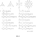
- FIG. 2 is a structural diagram of the main "discs” in common discotic liquid crystal molecules; as can be seen from FIG.
- the number of Benzene-ring(s) in the main “discs” may be 1, 3, 4 and 7; however, the number of Benzene-ring(s) in the main “discs” of the discotic liquid crystal molecules that can be employed in this embodiment is not limited thereto.
- the content of the discotic liquid will affect the effect on the induced-arrangement of the nematic liquid crystal; the general rule is: at a less the content the discotic liquid crystal is, the sparser the polymer network generated after polymerization is, and in turn a worse effect of the induced alignment of the nematic liquid crystal is incurred; at a more content of the discotic liquid crystal content is, the denser the polymer network generated after polymerization is, and in turn a better effect of the induced alignment of the nematic liquid crystal.
- the mass percentage of discotic liquid crystal is 8% or 9 %.
- the mechanical properties of the generated polymer network are also different.
- the number of the double-bond functional groups contained in the branch chains of the discotic liquid crystal will affect the rate of polymerization of the discotic liquid crystal.
- the mass percentage of discotic liquid crystal is 6%
- the mass percentage of photoinitiator is 1%
- the mass percentage of nematic liquid crystal is 93%; and the mixture, obtained in such a proportion through step 101 to step 105, can anchor the nematic liquid crystal, thereby making the alignment of the nematic liquid crystal uniform within a liquid crystal cell.
- the mass percentage of discotic liquid crystal is 8%, the mass percentage of photoinitiator is 2%, and the mass percentage of nematic liquid crystal is 90%; and the mixture, obtained in such a proportion through step 101 to step 105, can anchor the nematic liquid crystal, thereby making the alignment of the nematic liquid crystal uniform within a liquid crystal cell.
- the mass percentage of discotic liquid crystal is 5%
- the mass percentage of photoinitiator is 2%
- the mass percentage of nematic liquid crystal is 93%; and the mixture, obtained in such a proportion through step 101 to step 105, can anchor the nematic liquid crystal, thereby making the alignment of the nematic liquid crystal uniform within a liquid crystal cell.
- the mass percentage of discotic liquid crystal is 9%, the mass percentage of photoinitiator is 3%, and the mass percentage of nematic liquid crystal is 88%; and the mixture, obtained in such a proportion through step 101 to step 105, can anchor the nematic liquid crystal, thereby making the alignment of the nematic liquid crystal uniform within a liquid crystal cell.
- the mass percentage of discotic liquid crystal is 10%
- the mass percentage of photoinitiator is 6%
- the mass percentage of nematic liquid crystal is 84%
- the mixture obtained in such a proportion through step 101 to step 105, can anchor the nematic liquid crystal, thereby making the alignment of the nematic liquid crystal uniform within a liquid crystal cell.
- discotic liquid crystal; nematic liquid crystal and photoinitiator are mixed in a certain ratio and added dropwise on the substrate formed with an alignment layer, then vacuum cell-assembling is performed; thereafter, under the action of UV-light irradiation, the discotic liquid crystal is enabled to generate a polymer network, thereby anchoring the alignment of the nematic liquid crystal, so that the alignment of the nematic liquid crystal relatively far away from the alignment layer can be uniform with the alignment of the nematic liquid crystal close to the alignment layer, and thus the response time of the liquid crystal panel display can be reduced.
Landscapes
- Physics & Mathematics (AREA)
- Chemical & Material Sciences (AREA)
- Nonlinear Science (AREA)
- Crystallography & Structural Chemistry (AREA)
- Optics & Photonics (AREA)
- General Physics & Mathematics (AREA)
- Mathematical Physics (AREA)
- Materials Engineering (AREA)
- Organic Chemistry (AREA)
- Engineering & Computer Science (AREA)
- Spectroscopy & Molecular Physics (AREA)
- Dispersion Chemistry (AREA)
- Liquid Crystal (AREA)
- Polarising Elements (AREA)
Description
- Embodiments of the present invention relate to a liquid crystal display panel and a manufacturing method thereof.
- Depending on the requirements for different display modes, in a liquid crystal display using nematic liquid crystal, the alignment of the nematic liquid crystal between substrates has different manors. Generally, there are two alignment manors of nematic liquid crystal: nematic liquid crystal planar-alignment mode and nematic liquid crystal vertical-alignment mode.
- When the display mode is TN (twisted nematic, (orientation of liquid crystal molecules form a 90-degree twist)), STN (super twisted nematic, a 180-degree twisted nematic), IPS (in-plane switching), FFS (fringe field switching) or the like, a planar-aligning method is adopted to induce the alignment of nematic liquid crystal. For example, a preparation method is as follows.
- 1. An alignment layer is formed, by applying an aligning agent (for example, polyimide (PI) or polyvinyl alcohol (PVA)) on a surface of a substrate.
- 2. The alignment layer on a substrate surface is dried.
- 3. The substrate surface having the alignment layer is rubbed after the drying process, so that a plurality of microgrooves are formed on the substrate having the alignment layer.
- 4. Nematic liquid crystal is added dropwise on the substrate formed with grooves, and then a liquid crystal layer is sandwiched between two substrates after a liquid crystal cell is formed. Under the action of the alignment layer formed on the substrates, the nematic liquid crystal molecules are induced in an alignment.
- When the display mode is MVA (multi-domain vertical-alignment), a different aligning agent may be adopted to induce the alignment of nematic liquid crystal. A preparation method for that aligning agent is substantially the same as the planar-aligning method; siloxane may be elected as the aligning agent for vertical-alignment; the silicone is applied on a substrate surface and then dried; silicone adheres to the substrate by chemical bonds, and the flexible chain groups at ends of siloxane are capable of inducing nematic liquid crystal in an arrangement perpendicular to the substrate.
- The above are two common aligning methods for liquid crystal; they both achieve liquid crystal alignment through treatment onto a substrate surface. The alignment mechanism is that, by inducing the alignment of the liquid crystal which is close to a surface of an alignment layer, the nematic liquid crystal within the entirety of a liquid crystal cell is caused to be arranged. However, the alignment layer applied on a substrate has less action on the liquid crystal molecules far away from the alignment layer, so that the aligning action on the liquid crystal molecules is non-uniform, thereby affecting liquid crystal display effect.
-
US 6 497 928 B1 discloses a liquid crystal device having a liquid crystal layer of a liquid crystal composition comprising a discotic mesomorphic compound and a rod-shaped mesomorphic compound. The discotic mesomorphic compound and the rod-shaped mesomorphic compound are essentially mutually different in molecular structure and refractive index anisotropy and are co-present in the liquid crystal layer in a mutual phase separation state, thus improving a light-scattering performance of the liquid crystal device. -
US 2005/200800 A1 discloses a method of manufacturing a liquid crystal display device. The method includes a defoaming treatment step of defoaming a liquid crystal composition mixed a liquid crystal and a polymerizable component to be polymerized by light or heat; a liquid crystal composition dropping step of dropping or transferring the liquid crystal composition onto one substrate; a substrate-attaching step of attaching the one substrate and the other substrate together in vacuum, and filling the liquid crystal composition therein by returning vacuum back to the atmospheric pressure; and a polymerizing step of polymerizing the polymerizable component. - It is an object of the present invention to provide a liquid crystal display panel and a manufacturing method thereof for making the alignment of the nematic liquid crystal within a liquid crystal cell and far away from an alignment layer uniform with the alignment of the nematic liquid crystal close to the alignment layer, and thereby reducing the response speed of the liquid crystal panel.
- The object is achieved by the features of the respective independent claims. Further embodiments are defined in the respective dependent claims.
- In the embodied liquid crystal panel, for example, the photoinitiator is one or more substances from dibenzoyl peroxide, lauroyl peroxide, azobisisobutyronitrile, azobisisoheptonitrile, diisopropyl peroxydicarbonate, or dicyclohexyl peroxydicarbonate.
- In the embodied method, for example, the UV-light wavelength is 350nm∼390nm; the
- In order to clearly illustrate the technical solutions of the embodiments of the invention, the drawings of the embodiments will be briefly described in the following; it is obvious that the described drawings are only related to some embodiments of the invention and thus are not limitative of the invention defined in the claims.
-
FIG. 1 is a schematic flowchart of a manufacturing method for a liquid crystal display panel according to the present invention; -
FIG. 2 is a structural diagram of benzene-ring(s) in common discotic liquid crystal molecules; -
FIG. 3(a) is a schematic structural diagram of a liquid crystal display panel according to the present invention, under the action of a vertical-aligning agent and before UV-light irradiation; -
FIG. 3(b) is a schematic structural diagram of a liquid crystal display panel according to the present invention, under the action of a vertical-aligning agent and after UV-light irradiation; -
FIG. 4(a) is a schematic structural diagram of a liquid crystal display panel according to the present invention, under the action of a planar-aligning agent and before UV-light irradiation; -
FIG. 4(b) is a schematic structural diagram of a liquid crystal display panel according to the present invention, under the action of a planar-aligning agent and after UV-light irradiation; -
FIG. 5 is an electron-micrograph of a polymer network after polymerization of discotic liquid crystal; -
FIG. 6(a) is a polarization photograph of nematic liquid crystal, which is not in an alignment by induced discotic liquid crystal; -
FIG. 6(b) is a polarization photograph of nematic liquid crystal in a planar-alignment induced by discotic liquid crystal; and -
FIG. 6(c) is a polarization photograph of nematic liquid crystal in a vertical-alignment induced by discotic liquid crystal. - In order to make objects, technical details and advantages of the embodiments of the invention apparent, the technical solutions of the embodiments will be described in a clearly and fully understandable way in connection with the drawings related to the embodiments of the invention.
- Unless otherwise defined, technical jargon or scientific terms used herein should be interpreted in the usual sense as understood by those ordinary skilled in the relevant art of the present invention. The terms "first", "second", and the like, used in the specification and claims of this patent application of the invention, do not denote any order, quantity, or importance, but are used to distinguish among different integral parts. Similarly, the terms "a", "an", "the" and the like, herein do not denote a limitation of quantity, but rather denote the presence of at least one of the referenced item. The phases "connection" or "connected" or the like, are not limited to physical or mechanical connections, but may comprise electrical connection, whether direct or indirect. The phases "on", "under", "left", "right" and the like, are only used to indicate a relative positional relationship, which may be correspondingly changed as an absolute position of a described object is changed.
- As shown in
FIG. 1 , it is a schematic flowchart of a manufacturing method for a liquid crystal display panel provided by the present invention. The manufacturing method for a liquid crystal display panel comprises steps as follows. - Step 101: mixing discotic liquid crystal, nematic liquid crystal and photo initiator in a certain ratio and stirring with protection from light to obtain a mixture.
- Here, "a certain ratio" refers to the case in which, in the mixture, the mass percentage of nematic liquid crystal the mass percentage of discotic liquid crystal, and the mass percentage of photoinitiator are as defined in the appended
independent method claim 3. - The nematic liquid crystal may be a kind of commonly used liquid crystal currently available in the market, which is typically a mixture of liquid single-crystal which is composed of 20-30 parts by mass. The photoinitiator is, for example, benzoin anisole or the like.
- The reason for this and subsequent steps to be operated with protection from light is that, when photoinitiator is mixed in the liquid crystal, UV component in light will activate the photoinitiator to act and thus lead to polymerization. Therefore, the condition of "with protection from light" can be met, provided that polymerization induced by light can be avoided.
- Preferably, the mass percentage of discotic liquid crystal is selected as defined in the claims.
- The photoinitiator generally may choose dibenzoyl peroxide, lauroyl peroxide, azobisisobutyronitrile, azobisisoheptonitrile, diisopropyl peroxydicarbonate, or dicyclohexyl peroxydicarbonate, or the like.
- Because discotic liquid crystal has a unique disc-like molecular structure and is strongly miscible with nematic liquid crystal, discotic liquid crystal has fluidity in nematic liquid crystal; moreover, by stirring the mixture, discotic liquid crystal and nematic liquid crystal can be better mutually-miscible, so that a relatively stable solution is formed.
- Step 102: performing defoaming treatment on the mixture in a defoaming machine with protection from light.
- The duration of the defoaming treatment may be 1∼20 hours.
- Step 103: applying an aligning agent onto a substrate and performing corresponding treatment to form an alignment layer.
- The alignment layer thus formed will undergo treatments for aligning liquid crystal. A process for the treatments comprises: drying and rubbing, etc.
- Depending on the different required orientations for the alignment of nematic liquid crystal, a different kind of aligning agents may be chosen. For example, if it is required that nematic liquid crystal is aligned parallel to the substrate, then the aligning agent may be polyimide (PI), polyvinyl alcohol (PVA), etc.; if it is required that nematic liquid crystal is aligned perpendicular to the substrate, then the aligning agent may be siloxane, etc.
- The substrate may be an array substrate and/or a substrate disposed opposite to an array substrate (for example, a CF (color filter) substrate).
- Step 104: with protection from light, adding dropwise the mixture obtained in
step 101 on the substrate formed with the alignment layer, and in a vacuum cell-assembling process, assembling the substrate having the added mixture with another substrate to form a cell. - The vacuum cell-assembling process refers to the process in which, under a certain vacuum condition (under reduced pressure), two substrates, which are used for forming a liquid crystal panel, are disposed opposite to each other and form a liquid crystal cell with sealant.
- As the inner surface of a substrate of the liquid crystal cell after cell-assembling is formed with the alignment layer, the layer can induce the alignment of the nematic liquid crystal in the mixture, and the plane-direction of the main "discs" of the discotic liquid crystal molecules is parallel to the long-axis direction of nematic liquid crystal. In other words, when the aligning agent is siloxane, a vertical-
alignment layer 3 is formed on the surface of thesubstrate 4, the nematicliquid crystal 2 is aligned perpendicular to thesubstrate 4, and at this time the planes of the discoticliquid crystal molecules 1 are also perpendicular to thesubstrate 4; when the aligning agent is polyimide (PI), polyvinyl alcohol (PVA), a horizontal-alignment layer 6 is formed on the surface of thesubstrate 4, the nematicliquid crystal 2 is aligned parallel to thesubstrate 4, and at this time the planes of the discoticliquid crystal molecules 1 are also parallel to thesubstrate 4, as shown inFIG. 3(a) andFIG. 4(a) . - It also should be noted that, the implementation process of this
step 104 should be operated with protection from light. - Step 105: irradiating the substrates after cell-assembling with UV-light so that the photoinitiator is induced to generate free radicals, and the discotic
liquid crystal molecules 1 are polymerized to form a discotic liquidcrystal polymer network 5, thereby anchoring the alignment of the nematicliquid crystal molecules 2. -
FIG. 3(b) andFIG. 4(b) show schematic structural diagrams of a liquid crystal layer after UV-light irradiation; as can be seen, the discoticliquid crystal 1 in the mixture, under the action of the free radicals generated from the photoinitiator due to the induction of the UV irradiation, is polymerized and thus forms apolymer network 5. Due to the action of thepolymer network 5, the location of the discotic liquid crystal in the liquid crystal cell is fixed, so that the nematicliquid crystal 2 is aligned vertically or planarly in accordance with the discotic liquid crystal, thereby anchoring the alignment of the nematic liquid crystal, and making the alignment of the nematic liquid crystal within the liquid crystal cell uniform. - It should be noted that, the basic conditions of the UV-light irradiation may be as follows. The UV-light wavelength is selected from the range of 350nm∼390nm, and usually the UV-light wavelength is selected as 365nm; the UV-light irradiation time duration is 1∼180 minutes; and the UV-light irradiation intensity is 0.1∼100mW/cm2.
- In this embodiment, branch chains, which contain double-bond functional groups, are introduced onto the disc-like molecules of the discotic liquid crystal; under the action of the free radicals, the double-bond functional groups on the discotic liquid crystal molecules are polymerized, forming a discotic liquid crystal polymer network. The polymer network is a spatial network structure, which can fix the location of the main "discs" of the discotic liquid crystal in the liquid crystal cell, and cause the nematic liquid crystal to be aligned in accordance with the planes of the discotic liquid crystal.
- Discotic liquid crystal is composed of main "discs" and branch chains; when the structure of the main "discs" in the discotic liquid crystal is different, after polymerization, the effect on the induced alignment of the nematic liquid crystal is accordingly different. The larger the number of benzene-ring(s) in the main "discs", the greater the effect on the induced alignment of the nematic liquid crystal.
FIG. 2 is a structural diagram of the main "discs" in common discotic liquid crystal molecules; as can be seen fromFIG. 2 , the number of Benzene-ring(s) in the main "discs" may be 1, 3, 4 and 7; however, the number of Benzene-ring(s) in the main "discs" of the discotic liquid crystal molecules that can be employed in this embodiment is not limited thereto. - Furthermore, the content of the discotic liquid will affect the effect on the induced-arrangement of the nematic liquid crystal; the general rule is: at a less the content the discotic liquid crystal is, the sparser the polymer network generated after polymerization is, and in turn a worse effect of the induced alignment of the nematic liquid crystal is incurred; at a more content of the discotic liquid crystal content is, the denser the polymer network generated after polymerization is, and in turn a better effect of the induced alignment of the nematic liquid crystal. However, when the content of the discotic liquid crystal is too high, the solubility of the discotic liquid crystal in the nematic liquid crystal molecules will be degraded, and this will consequently suppress the alignment of the nematic liquid crystal. Accordingly, when discotic liquid crystal, nematic liquid crystal and photoinitiator are mixed in a certain ratio, the mass percentage of discotic liquid crystal is 8% or 9 %.
- It should be noted that, when the mass percentage of discotic liquid crystal is 5∼10%, the effect on the alignment of the nematic liquid crystal is best, as shown in
FIG. 6(b) and FIG. 6(c) ; as can be seen from the comparison ofFIG. 6(b)-6(c) withFIG. 6(a) , there is an obvious schlieren structure inFIG. 6 (a) , while inFIG. 6(b) and FIG. 6(c) , due to the addition of discotic liquid crystal, the schlieren structure disappears, which indicates that, under the action of the discotic liquid crystal polymer network, the alignment of the nematic liquid crystal tends to be uniform. - In addition, when the structure of the branched-chains in the discotic liquid crystal molecules is different, the mechanical properties of the generated polymer network are also different. The larger the number of discotic liquid crystal molecules having benzene-ring(s) or naphthalene-ring(s) contained in the branch chains thereof is, the stronger rigidity and the better mechanical properties of the generated polymer network possesses; the larger the number of discotic liquid crystal molecules having ester-groups contained in the branch chains thereof is, the weaker rigidity and the worse mechanical properties of the generated polymer network possesses.
- Furthermore, the number of the double-bond functional groups contained in the branch chains of the discotic liquid crystal will affect the rate of polymerization of the discotic liquid crystal. The smaller the number of double-bond functional groups contained in the branch chains of the discotic liquid crystal is, the slower polymerization rate the discotic liquid crystal has under the action of UV-light and photoinitiator; the larger the number of double-bond functional groups contained in the branch chains of the discotic liquid crystal is, the faster polymerization rate the discotic liquid crystal has under the action of UV-light and photoinitiator.
- First Example useful for understanding the invention.
- In this example, in the above-described
step 101, the mass percentage of discotic liquid crystal is 6%, the mass percentage of photoinitiator is 1%, and the mass percentage of nematic liquid crystal is 93%; and the mixture, obtained in such a proportion throughstep 101 to step 105, can anchor the nematic liquid crystal, thereby making the alignment of the nematic liquid crystal uniform within a liquid crystal cell. - In this embodiment, in the above-described
step 101, the mass percentage of discotic liquid crystal is 8%, the mass percentage of photoinitiator is 2%, and the mass percentage of nematic liquid crystal is 90%; and the mixture, obtained in such a proportion throughstep 101 to step 105, can anchor the nematic liquid crystal, thereby making the alignment of the nematic liquid crystal uniform within a liquid crystal cell. - In this example, in the above-described
step 101, the mass percentage of discotic liquid crystal is 5%, the mass percentage of photoinitiator is 2%, and the mass percentage of nematic liquid crystal is 93%; and the mixture, obtained in such a proportion throughstep 101 to step 105, can anchor the nematic liquid crystal, thereby making the alignment of the nematic liquid crystal uniform within a liquid crystal cell. - In this embodiment, in the above-described
step 101, the mass percentage of discotic liquid crystal is 9%, the mass percentage of photoinitiator is 3%, and the mass percentage of nematic liquid crystal is 88%; and the mixture, obtained in such a proportion throughstep 101 to step 105, can anchor the nematic liquid crystal, thereby making the alignment of the nematic liquid crystal uniform within a liquid crystal cell. - In this example, in the above-described
step 101, the mass percentage of discotic liquid crystal is 10%, the mass percentage of photoinitiator is 6%, and the mass percentage of nematic liquid crystal is 84%; and the mixture, obtained in such a proportion throughstep 101 to step 105, can anchor the nematic liquid crystal, thereby making the alignment of the nematic liquid crystal uniform within a liquid crystal cell. - The above give out two preferred embodiments of the present invention. In the present solution, discotic liquid crystal; nematic liquid crystal and photoinitiator are mixed in a certain ratio and added dropwise on the substrate formed with an alignment layer, then vacuum cell-assembling is performed; thereafter, under the action of UV-light irradiation, the discotic liquid crystal is enabled to generate a polymer network, thereby anchoring the alignment of the nematic liquid crystal, so that the alignment of the nematic liquid crystal relatively far away from the alignment layer can be uniform with the alignment of the nematic liquid crystal close to the alignment layer, and thus the response time of the liquid crystal panel display can be reduced.
Claims (6)
- A liquid crystal display panel, comprising: two substrates disposed opposite to each other and a liquid crystal layer filled between the two substrates, wherein the liquid crystal layer is formed by UV-light irradiation of a mixture consisting of a discotic liquid crystal (1), a nematic liquid crystal (2) and a photoinitiator, characterized in that
the mass percentage of the discotic liquid crystal (1) is 9%, the mass percentage of the photoinitiator is 3%, and the mass percentage of the nematic liquid crystal is 88%; or
the mass percentage of the discotic liquid crystal (1) is 8%, the mass percentage of the photoinitiator is 2%, and the mass percentage of the nematic liquid crystal is 90%. - The liquid crystal panel according to Claim 1, wherein the photoinitiator is one or a mixture of two or more substances selected from dibenzoyl peroxide, lauroyl peroxide, azobisisobutyronitrile, azobisisoheptonitrile, diisopropyl peroxydicarbonate, and dicyclohexyl peroxydicarbonate.
- A manufacturing method for a liquid crystal display panel, comprising:forming an alignment layer by applying an aligning agent on at least one (4) of two substrates adapted for manufacture of a liquid crystal panel;mixing (101) a discotic liquid crystal (1), a nematic liquid crystal (2) and a photoinitiator and stirring with protection from light to obtain a mixture;adding dropwise the mixture onto the substrate (4) formed with the alignment layer, with protection from light, and then performing cell-assembling with protection from light; andirradiating (104) the substrates after cell-assembling with UV-light, so that the discotic liquid crystal (1) is polymerized under action of the photoinitiator to form a discotic liquid crystal polymer network,
characterized in that,in the mixture, the mass percentage of the discotic liquid crystal is 9%, the mass percentage of the photo initiator is 3%, and the mass percentage of the nematic liquid crystal is 88%; orin the mixture, the mass percentage of the discotic liquid crystal (1) is 8%, the mass percentage of the photoinitiator is 2%, and the mass percentage of the nematic liquid crystal is 90%. - The manufacturing method for a liquid crystal display panel according to Claim 3, wherein the UV-light wavelength is 350nm∼390nm; the UV-light irradiation time duration is 1∼180 minutes; and the UV-light irradiation intensity is 0.1∼100mW/cm2.
- The manufacturing method for a liquid crystal display panel according to Claim 3 or 4, wherein the mixture is defoamed (102) with protection from light before the mixture is added dropwise on the substrate applied with the aligning agent.
- The manufacturing method for a liquid crystal display panel according to any one of Claims 3-5, wherein the photoinitiator is dibenzoyl peroxide, lauroyl peroxide, azobisisobutyronitrile, azobisisoheptonitrile, diisopropyl peroxydicarbonate, or dicyclohexyl peroxydicarbonate.
Applications Claiming Priority (2)
| Application Number | Priority Date | Filing Date | Title |
|---|---|---|---|
| CN201210060315.6A CN102645778B (en) | 2012-03-08 | 2012-03-08 | A kind of display panels and preparation method thereof |
| PCT/CN2012/084245 WO2013131379A1 (en) | 2012-03-08 | 2012-11-07 | Liquid crystal display panel and manufacturing method thereof |
Publications (3)
| Publication Number | Publication Date |
|---|---|
| EP2653914A1 EP2653914A1 (en) | 2013-10-23 |
| EP2653914A4 EP2653914A4 (en) | 2015-09-02 |
| EP2653914B1 true EP2653914B1 (en) | 2018-09-19 |
Family
ID=46658686
Family Applications (1)
| Application Number | Title | Priority Date | Filing Date |
|---|---|---|---|
| EP12830909.3A Not-in-force EP2653914B1 (en) | 2012-03-08 | 2012-11-07 | Liquid crystal display panel and manufacturing method thereof |
Country Status (6)
| Country | Link |
|---|---|
| US (1) | US9904092B2 (en) |
| EP (1) | EP2653914B1 (en) |
| JP (1) | JP6144708B2 (en) |
| KR (1) | KR101584415B1 (en) |
| CN (1) | CN102645778B (en) |
| WO (1) | WO2013131379A1 (en) |
Families Citing this family (39)
| Publication number | Priority date | Publication date | Assignee | Title |
|---|---|---|---|---|
| CN102629013B (en) | 2011-09-15 | 2014-12-17 | 北京京东方光电科技有限公司 | Liquid crystal display device and manufacturing method thereof |
| CN102645778B (en) * | 2012-03-08 | 2016-01-27 | 北京京东方光电科技有限公司 | A kind of display panels and preparation method thereof |
| CN102902094B (en) * | 2012-09-28 | 2015-03-25 | 北京京东方光电科技有限公司 | TN-typed liquid crystal display panel and manufacturing method thereof |
| CN103207469B (en) | 2013-03-18 | 2016-01-27 | 北京京东方光电科技有限公司 | The manufacture method of liquid crystal panel, display device and liquid crystal panel |
| CN103869544B (en) * | 2014-02-14 | 2016-06-29 | 北京京东方光电科技有限公司 | The preparation method of a kind of oriented layer, oriented layer compositions and display floater |
| WO2017074951A1 (en) | 2015-10-26 | 2017-05-04 | Reald Inc. | Intelligent privacy system, apparatus, and method thereof |
| CN114554177A (en) | 2016-05-19 | 2022-05-27 | 瑞尔D斯帕克有限责任公司 | Wide-angle imaging directional backlight |
| US10126575B1 (en) | 2017-05-08 | 2018-11-13 | Reald Spark, Llc | Optical stack for privacy display |
| US20210199879A1 (en) | 2017-05-08 | 2021-07-01 | Reald Spark, Llc | Optical stack for imaging directional backlights |
| JP7204073B2 (en) | 2017-05-08 | 2023-01-16 | リアルディー スパーク エルエルシー | Optical stacks for directional displays |
| TWI878209B (en) | 2017-09-15 | 2025-04-01 | 美商瑞爾D斯帕克有限責任公司 | Display device and a view angle control optical element for application to a display device |
| US10948648B2 (en) | 2017-09-29 | 2021-03-16 | Reald Spark, Llc | Backlights having stacked waveguide and optical components with different coefficients of friction |
| WO2019090252A1 (en) | 2017-11-06 | 2019-05-09 | Reald Spark, Llc | Privacy display apparatus |
| TWI827580B (en) | 2018-01-25 | 2024-01-01 | 美商瑞爾D斯帕克有限責任公司 | Reflective optical stack for privacy display |
| KR102759510B1 (en) | 2018-01-25 | 2025-02-04 | 리얼디 스파크, 엘엘씨 | Touchscreen for privacy display |
| EP3769516B1 (en) | 2018-03-22 | 2025-06-25 | RealD Spark, LLC | Optical waveguide for directional backlight |
| US10955715B2 (en) | 2018-06-29 | 2021-03-23 | Reald Spark, Llc | Optical stack for privacy display |
| CN112602011A (en) | 2018-07-18 | 2021-04-02 | 瑞尔D斯帕克有限责任公司 | Optical stack for switchable directional display |
| WO2020072643A1 (en) | 2018-10-03 | 2020-04-09 | Reald Spark, Llc | Privacy display control apparatus |
| WO2020097156A1 (en) | 2018-11-07 | 2020-05-14 | Reald Spark, Llc | Directional display apparatus |
| WO2020146091A1 (en) | 2019-01-07 | 2020-07-16 | Reald Spark, Llc | Optical stack for privacy display |
| EP3924776B1 (en) | 2019-02-12 | 2024-07-10 | RealD Spark, LLC | Display device with diffuser for privacy display |
| TWI912252B (en) | 2019-07-02 | 2026-01-21 | 美商瑞爾D斯帕克有限責任公司 | Directional display apparatus |
| WO2021026018A1 (en) | 2019-08-02 | 2021-02-11 | Reald Spark, Llc | Optical stack for privacy display |
| EP4438945B1 (en) | 2019-10-02 | 2025-09-03 | RealD Spark, LLC | Privacy display apparatus |
| WO2021097040A1 (en) | 2019-11-13 | 2021-05-20 | Reald Spark, Llc | Display device with uniform off-axis luminance reduction |
| WO2021118936A1 (en) | 2019-12-10 | 2021-06-17 | Reald Spark, Llc | Control of reflections of a display device |
| CN114902093B (en) | 2019-12-18 | 2025-09-26 | 瑞尔D斯帕克有限责任公司 | Ambient light control for privacy displays |
| WO2021222606A1 (en) | 2020-04-30 | 2021-11-04 | Reald Spark, Llc | Directional display apparatus |
| EP4143631A4 (en) | 2020-04-30 | 2024-05-29 | RealD Spark, LLC | Directional display apparatus |
| US11442316B2 (en) | 2020-04-30 | 2022-09-13 | Reald Spark, Llc | Directional display apparatus |
| TWI898003B (en) | 2020-07-29 | 2025-09-21 | 美商瑞爾D斯帕克有限責任公司 | Pupillated illumination apparatus |
| WO2022026536A1 (en) | 2020-07-29 | 2022-02-03 | Reald Spark, Llc | Backlight for switchable directional display |
| US11892717B2 (en) | 2021-09-30 | 2024-02-06 | Reald Spark, Llc | Marks for privacy display |
| WO2023154217A1 (en) | 2022-02-09 | 2023-08-17 | Reald Spark, Llc | Observer-tracked privacy display |
| TW202332973A (en) | 2022-02-09 | 2023-08-16 | 美商瑞爾D斯帕克有限責任公司 | Display device with uniform off-axis luminance reduction |
| CN119053908A (en) | 2022-04-07 | 2024-11-29 | 瑞尔D斯帕克有限责任公司 | Directional display device |
| WO2024226506A1 (en) | 2023-04-25 | 2024-10-31 | Reald Spark, Llc | Switchable privacy display |
| WO2025030030A2 (en) | 2023-08-03 | 2025-02-06 | Reald Spark, Llc | Privacy displays |
Family Cites Families (15)
| Publication number | Priority date | Publication date | Assignee | Title |
|---|---|---|---|---|
| US6497928B1 (en) * | 1999-05-14 | 2002-12-24 | Canon Kabushiki Kaisha | Liquid crystal device, mesomorphic functional material and liquid crystal apparatus |
| JP3862473B2 (en) | 1999-05-14 | 2006-12-27 | キヤノン株式会社 | Liquid crystal element, liquid crystal functional material, and liquid crystal device |
| KR100741903B1 (en) | 2000-10-23 | 2007-07-24 | 엘지.필립스 엘시디 주식회사 | Liquid dropping LCD panel and manufacturing method thereof |
| JP2002146353A (en) * | 2000-11-13 | 2002-05-22 | Chisato Kajiyama | Liquid crystal optical materials using polymer networks formed from polymerizable disc-shaped monomers |
| KR100752507B1 (en) * | 2000-12-22 | 2007-08-28 | 엘지.필립스 엘시디 주식회사 | Ferroelectric liquid crystal display device and manufacturing method thereof |
| WO2003102045A1 (en) * | 2002-05-31 | 2003-12-11 | Elsicon, Inc. | Hybrid polymer materials for liquid crystal alignment layers |
| JP4569189B2 (en) * | 2003-06-23 | 2010-10-27 | チッソ株式会社 | Liquid crystal compound, liquid crystal composition and polymer thereof |
| TWI252341B (en) * | 2004-01-15 | 2006-04-01 | Sharp Kk | Display element, display device, and manufacturing method of display element |
| JP4744090B2 (en) * | 2004-03-11 | 2011-08-10 | 富士通株式会社 | Manufacturing method of liquid crystal display device |
| US7604850B2 (en) * | 2005-08-24 | 2009-10-20 | Kent State University | Biaxial liquid crystal electro-optic devices |
| KR101166831B1 (en) | 2005-09-27 | 2012-07-23 | 엘지디스플레이 주식회사 | Method and apparatus of fabricating liquid crystal display device |
| TW200804476A (en) * | 2005-11-25 | 2008-01-16 | Fujifilm Corp | Cellulose acylate film, method of producing the same, cellulose derivative film, optically compensatory film using the same, optically-compensatory film incorporating polarizing plate, polarizing plate and liquid crystal display device |
| JP4708287B2 (en) * | 2006-08-25 | 2011-06-22 | 富士フイルム株式会社 | Manufacturing method of optical film, optical film, polarizing plate, transfer material, liquid crystal display device, and polarized ultraviolet exposure device |
| CN102354081A (en) * | 2011-11-10 | 2012-02-15 | 范志新 | Stressed liquid crystal transparent projection screen as well as preparation method and application thereof |
| CN102645778B (en) | 2012-03-08 | 2016-01-27 | 北京京东方光电科技有限公司 | A kind of display panels and preparation method thereof |
-
2012
- 2012-03-08 CN CN201210060315.6A patent/CN102645778B/en not_active Expired - Fee Related
- 2012-11-07 WO PCT/CN2012/084245 patent/WO2013131379A1/en not_active Ceased
- 2012-11-07 JP JP2014560219A patent/JP6144708B2/en not_active Expired - Fee Related
- 2012-11-07 KR KR1020137010101A patent/KR101584415B1/en not_active Expired - Fee Related
- 2012-11-07 EP EP12830909.3A patent/EP2653914B1/en not_active Not-in-force
- 2012-11-07 US US13/824,526 patent/US9904092B2/en not_active Expired - Fee Related
Non-Patent Citations (1)
| Title |
|---|
| None * |
Also Published As
| Publication number | Publication date |
|---|---|
| EP2653914A1 (en) | 2013-10-23 |
| CN102645778B (en) | 2016-01-27 |
| EP2653914A4 (en) | 2015-09-02 |
| KR20130126598A (en) | 2013-11-20 |
| JP2015509617A (en) | 2015-03-30 |
| KR101584415B1 (en) | 2016-01-11 |
| WO2013131379A1 (en) | 2013-09-12 |
| US9904092B2 (en) | 2018-02-27 |
| JP6144708B2 (en) | 2017-06-07 |
| CN102645778A (en) | 2012-08-22 |
| US20140111760A1 (en) | 2014-04-24 |
Similar Documents
| Publication | Publication Date | Title |
|---|---|---|
| US9904092B2 (en) | Liquid crystal display panel using discotic liquid crystal to induce alignment of nematic liquid crystal and manufacturing method thereof | |
| KR101725997B1 (en) | Liquid crystal display device including alignment control layer containing polymerized mesogen, and method for fabricating the device | |
| TWI710840B (en) | Light modulation element and production methods and uses thereof | |
| CN102786936B (en) | Liquid crystal medium composition | |
| CN105629583B (en) | Liquid crystal display device with a light guide plate | |
| JP6178514B2 (en) | Liquid crystal medium composition | |
| US20130271713A1 (en) | Liquid crystal display device and method for manufacturing liquid crystal display device | |
| KR101824055B1 (en) | Liquid crystal display device and method of fabricating the same | |
| US9249242B2 (en) | Method for manufacturing liquid crystal display device | |
| TW201219932A (en) | Liquid crystal display and method for preparation thereof | |
| WO2014127562A1 (en) | Liquid crystal panel manufacturing method, liquid crystal mixture, and liquid crystal panel | |
| US20140168589A1 (en) | Liquid crystal display panel and liquid crystal display device | |
| WO2013031393A1 (en) | Liquid-crystal display panel and liquid-crystal display device | |
| CN103881729B (en) | Liquid crystal material, display panels and manufacture method thereof | |
| WO2014172925A1 (en) | Polymerizable mixture and liquid crystal composition thereof | |
| WO2011004518A1 (en) | Liquid crystal display panel and process for production thereof | |
| TWI556029B (en) | Fabricating method of liquid crystal device | |
| TWI762446B (en) | Method of reducing odf mura in polymer stabilised liquid crystal displays | |
| WO2011078126A1 (en) | Tn liquid crystal element, and method for producing same | |
| EP2806012B1 (en) | Liquid crystal composition | |
| CN106281358A (en) | A kind of liquid crystal media mixture and display panels | |
| WO2014012279A1 (en) | Liquid crystal dielectric mixture for use in liquid crystal display device | |
| Oh et al. | Enhancement of viewing angle properties of a single-domain fringe-field switching mode using zero pretilt alignment | |
| CN1776483A (en) | A method of manufacturing a liquid crystal polarizer capable of broad-wave reflection | |
| CN108431683B (en) | Liquid crystal display device and method of manufacturing the same |
Legal Events
| Date | Code | Title | Description |
|---|---|---|---|
| PUAI | Public reference made under article 153(3) epc to a published international application that has entered the european phase |
Free format text: ORIGINAL CODE: 0009012 |
|
| 17P | Request for examination filed |
Effective date: 20130320 |
|
| AK | Designated contracting states |
Kind code of ref document: A1 Designated state(s): AL AT BE BG CH CY CZ DE DK EE ES FI FR GB GR HR HU IE IS IT LI LT LU LV MC MK MT NL NO PL PT RO RS SE SI SK SM TR |
|
| RAP1 | Party data changed (applicant data changed or rights of an application transferred) |
Owner name: BOE TECHNOLOGY GROUP CO., LTD. Owner name: BEIJING BOE OPTOELECTRONICS TECHNOLOGY CO. LTD. |
|
| DAX | Request for extension of the european patent (deleted) | ||
| RIC1 | Information provided on ipc code assigned before grant |
Ipc: C09K 19/00 20060101ALI20150722BHEP Ipc: G02F 1/1337 20060101AFI20150722BHEP |
|
| RA4 | Supplementary search report drawn up and despatched (corrected) |
Effective date: 20150731 |
|
| STAA | Information on the status of an ep patent application or granted ep patent |
Free format text: STATUS: EXAMINATION IS IN PROGRESS |
|
| 17Q | First examination report despatched |
Effective date: 20170328 |
|
| GRAP | Despatch of communication of intention to grant a patent |
Free format text: ORIGINAL CODE: EPIDOSNIGR1 |
|
| STAA | Information on the status of an ep patent application or granted ep patent |
Free format text: STATUS: GRANT OF PATENT IS INTENDED |
|
| INTG | Intention to grant announced |
Effective date: 20180411 |
|
| GRAS | Grant fee paid |
Free format text: ORIGINAL CODE: EPIDOSNIGR3 |
|
| GRAA | (expected) grant |
Free format text: ORIGINAL CODE: 0009210 |
|
| STAA | Information on the status of an ep patent application or granted ep patent |
Free format text: STATUS: THE PATENT HAS BEEN GRANTED |
|
| AK | Designated contracting states |
Kind code of ref document: B1 Designated state(s): AL AT BE BG CH CY CZ DE DK EE ES FI FR GB GR HR HU IE IS IT LI LT LU LV MC MK MT NL NO PL PT RO RS SE SI SK SM TR |
|
| REG | Reference to a national code |
Ref country code: GB Ref legal event code: FG4D |
|
| REG | Reference to a national code |
Ref country code: CH Ref legal event code: EP |
|
| REG | Reference to a national code |
Ref country code: FR Ref legal event code: PLFP Year of fee payment: 7 |
|
| REG | Reference to a national code |
Ref country code: AT Ref legal event code: REF Ref document number: 1043930 Country of ref document: AT Kind code of ref document: T Effective date: 20181015 |
|
| REG | Reference to a national code |
Ref country code: IE Ref legal event code: FG4D |
|
| REG | Reference to a national code |
Ref country code: DE Ref legal event code: R096 Ref document number: 602012051377 Country of ref document: DE |
|
| REG | Reference to a national code |
Ref country code: NL Ref legal event code: FP |
|
| PG25 | Lapsed in a contracting state [announced via postgrant information from national office to epo] |
Ref country code: NO Free format text: LAPSE BECAUSE OF FAILURE TO SUBMIT A TRANSLATION OF THE DESCRIPTION OR TO PAY THE FEE WITHIN THE PRESCRIBED TIME-LIMIT Effective date: 20181219 Ref country code: SE Free format text: LAPSE BECAUSE OF FAILURE TO SUBMIT A TRANSLATION OF THE DESCRIPTION OR TO PAY THE FEE WITHIN THE PRESCRIBED TIME-LIMIT Effective date: 20180919 Ref country code: RS Free format text: LAPSE BECAUSE OF FAILURE TO SUBMIT A TRANSLATION OF THE DESCRIPTION OR TO PAY THE FEE WITHIN THE PRESCRIBED TIME-LIMIT Effective date: 20180919 Ref country code: FI Free format text: LAPSE BECAUSE OF FAILURE TO SUBMIT A TRANSLATION OF THE DESCRIPTION OR TO PAY THE FEE WITHIN THE PRESCRIBED TIME-LIMIT Effective date: 20180919 Ref country code: BG Free format text: LAPSE BECAUSE OF FAILURE TO SUBMIT A TRANSLATION OF THE DESCRIPTION OR TO PAY THE FEE WITHIN THE PRESCRIBED TIME-LIMIT Effective date: 20181219 Ref country code: LT Free format text: LAPSE BECAUSE OF FAILURE TO SUBMIT A TRANSLATION OF THE DESCRIPTION OR TO PAY THE FEE WITHIN THE PRESCRIBED TIME-LIMIT Effective date: 20180919 Ref country code: GR Free format text: LAPSE BECAUSE OF FAILURE TO SUBMIT A TRANSLATION OF THE DESCRIPTION OR TO PAY THE FEE WITHIN THE PRESCRIBED TIME-LIMIT Effective date: 20181220 |
|
| REG | Reference to a national code |
Ref country code: LT Ref legal event code: MG4D |
|
| PG25 | Lapsed in a contracting state [announced via postgrant information from national office to epo] |
Ref country code: HR Free format text: LAPSE BECAUSE OF FAILURE TO SUBMIT A TRANSLATION OF THE DESCRIPTION OR TO PAY THE FEE WITHIN THE PRESCRIBED TIME-LIMIT Effective date: 20180919 Ref country code: AL Free format text: LAPSE BECAUSE OF FAILURE TO SUBMIT A TRANSLATION OF THE DESCRIPTION OR TO PAY THE FEE WITHIN THE PRESCRIBED TIME-LIMIT Effective date: 20180919 Ref country code: LV Free format text: LAPSE BECAUSE OF FAILURE TO SUBMIT A TRANSLATION OF THE DESCRIPTION OR TO PAY THE FEE WITHIN THE PRESCRIBED TIME-LIMIT Effective date: 20180919 |
|
| REG | Reference to a national code |
Ref country code: AT Ref legal event code: MK05 Ref document number: 1043930 Country of ref document: AT Kind code of ref document: T Effective date: 20180919 |
|
| PG25 | Lapsed in a contracting state [announced via postgrant information from national office to epo] |
Ref country code: CZ Free format text: LAPSE BECAUSE OF FAILURE TO SUBMIT A TRANSLATION OF THE DESCRIPTION OR TO PAY THE FEE WITHIN THE PRESCRIBED TIME-LIMIT Effective date: 20180919 Ref country code: RO Free format text: LAPSE BECAUSE OF FAILURE TO SUBMIT A TRANSLATION OF THE DESCRIPTION OR TO PAY THE FEE WITHIN THE PRESCRIBED TIME-LIMIT Effective date: 20180919 Ref country code: ES Free format text: LAPSE BECAUSE OF FAILURE TO SUBMIT A TRANSLATION OF THE DESCRIPTION OR TO PAY THE FEE WITHIN THE PRESCRIBED TIME-LIMIT Effective date: 20180919 Ref country code: PL Free format text: LAPSE BECAUSE OF FAILURE TO SUBMIT A TRANSLATION OF THE DESCRIPTION OR TO PAY THE FEE WITHIN THE PRESCRIBED TIME-LIMIT Effective date: 20180919 Ref country code: AT Free format text: LAPSE BECAUSE OF FAILURE TO SUBMIT A TRANSLATION OF THE DESCRIPTION OR TO PAY THE FEE WITHIN THE PRESCRIBED TIME-LIMIT Effective date: 20180919 Ref country code: EE Free format text: LAPSE BECAUSE OF FAILURE TO SUBMIT A TRANSLATION OF THE DESCRIPTION OR TO PAY THE FEE WITHIN THE PRESCRIBED TIME-LIMIT Effective date: 20180919 Ref country code: IS Free format text: LAPSE BECAUSE OF FAILURE TO SUBMIT A TRANSLATION OF THE DESCRIPTION OR TO PAY THE FEE WITHIN THE PRESCRIBED TIME-LIMIT Effective date: 20190119 Ref country code: IT Free format text: LAPSE BECAUSE OF FAILURE TO SUBMIT A TRANSLATION OF THE DESCRIPTION OR TO PAY THE FEE WITHIN THE PRESCRIBED TIME-LIMIT Effective date: 20180919 |
|
| PG25 | Lapsed in a contracting state [announced via postgrant information from national office to epo] |
Ref country code: PT Free format text: LAPSE BECAUSE OF FAILURE TO SUBMIT A TRANSLATION OF THE DESCRIPTION OR TO PAY THE FEE WITHIN THE PRESCRIBED TIME-LIMIT Effective date: 20190119 Ref country code: SM Free format text: LAPSE BECAUSE OF FAILURE TO SUBMIT A TRANSLATION OF THE DESCRIPTION OR TO PAY THE FEE WITHIN THE PRESCRIBED TIME-LIMIT Effective date: 20180919 Ref country code: SK Free format text: LAPSE BECAUSE OF FAILURE TO SUBMIT A TRANSLATION OF THE DESCRIPTION OR TO PAY THE FEE WITHIN THE PRESCRIBED TIME-LIMIT Effective date: 20180919 |
|
| REG | Reference to a national code |
Ref country code: DE Ref legal event code: R097 Ref document number: 602012051377 Country of ref document: DE |
|
| REG | Reference to a national code |
Ref country code: CH Ref legal event code: PL |
|
| PLBE | No opposition filed within time limit |
Free format text: ORIGINAL CODE: 0009261 |
|
| STAA | Information on the status of an ep patent application or granted ep patent |
Free format text: STATUS: NO OPPOSITION FILED WITHIN TIME LIMIT |
|
| PG25 | Lapsed in a contracting state [announced via postgrant information from national office to epo] |
Ref country code: LU Free format text: LAPSE BECAUSE OF NON-PAYMENT OF DUE FEES Effective date: 20181107 Ref country code: MC Free format text: LAPSE BECAUSE OF FAILURE TO SUBMIT A TRANSLATION OF THE DESCRIPTION OR TO PAY THE FEE WITHIN THE PRESCRIBED TIME-LIMIT Effective date: 20180919 Ref country code: DK Free format text: LAPSE BECAUSE OF FAILURE TO SUBMIT A TRANSLATION OF THE DESCRIPTION OR TO PAY THE FEE WITHIN THE PRESCRIBED TIME-LIMIT Effective date: 20180919 |
|
| REG | Reference to a national code |
Ref country code: BE Ref legal event code: MM Effective date: 20181130 |
|
| REG | Reference to a national code |
Ref country code: IE Ref legal event code: MM4A |
|
| 26N | No opposition filed |
Effective date: 20190620 |
|
| PG25 | Lapsed in a contracting state [announced via postgrant information from national office to epo] |
Ref country code: LI Free format text: LAPSE BECAUSE OF NON-PAYMENT OF DUE FEES Effective date: 20181130 Ref country code: CH Free format text: LAPSE BECAUSE OF NON-PAYMENT OF DUE FEES Effective date: 20181130 |
|
| PG25 | Lapsed in a contracting state [announced via postgrant information from national office to epo] |
Ref country code: SI Free format text: LAPSE BECAUSE OF FAILURE TO SUBMIT A TRANSLATION OF THE DESCRIPTION OR TO PAY THE FEE WITHIN THE PRESCRIBED TIME-LIMIT Effective date: 20180919 Ref country code: IE Free format text: LAPSE BECAUSE OF NON-PAYMENT OF DUE FEES Effective date: 20181107 |
|
| PG25 | Lapsed in a contracting state [announced via postgrant information from national office to epo] |
Ref country code: BE Free format text: LAPSE BECAUSE OF NON-PAYMENT OF DUE FEES Effective date: 20181130 |
|
| PG25 | Lapsed in a contracting state [announced via postgrant information from national office to epo] |
Ref country code: MT Free format text: LAPSE BECAUSE OF NON-PAYMENT OF DUE FEES Effective date: 20181107 |
|
| PG25 | Lapsed in a contracting state [announced via postgrant information from national office to epo] |
Ref country code: TR Free format text: LAPSE BECAUSE OF FAILURE TO SUBMIT A TRANSLATION OF THE DESCRIPTION OR TO PAY THE FEE WITHIN THE PRESCRIBED TIME-LIMIT Effective date: 20180919 |
|
| PG25 | Lapsed in a contracting state [announced via postgrant information from national office to epo] |
Ref country code: HU Free format text: LAPSE BECAUSE OF FAILURE TO SUBMIT A TRANSLATION OF THE DESCRIPTION OR TO PAY THE FEE WITHIN THE PRESCRIBED TIME-LIMIT; INVALID AB INITIO Effective date: 20121107 Ref country code: MK Free format text: LAPSE BECAUSE OF NON-PAYMENT OF DUE FEES Effective date: 20180919 Ref country code: CY Free format text: LAPSE BECAUSE OF FAILURE TO SUBMIT A TRANSLATION OF THE DESCRIPTION OR TO PAY THE FEE WITHIN THE PRESCRIBED TIME-LIMIT Effective date: 20180919 |
|
| PGFP | Annual fee paid to national office [announced via postgrant information from national office to epo] |
Ref country code: NL Payment date: 20201113 Year of fee payment: 9 |
|
| PGFP | Annual fee paid to national office [announced via postgrant information from national office to epo] |
Ref country code: FR Payment date: 20201013 Year of fee payment: 9 Ref country code: DE Payment date: 20201028 Year of fee payment: 9 Ref country code: GB Payment date: 20201028 Year of fee payment: 9 |
|
| REG | Reference to a national code |
Ref country code: DE Ref legal event code: R119 Ref document number: 602012051377 Country of ref document: DE |
|
| REG | Reference to a national code |
Ref country code: NL Ref legal event code: MM Effective date: 20211201 |
|
| GBPC | Gb: european patent ceased through non-payment of renewal fee |
Effective date: 20211107 |
|
| PG25 | Lapsed in a contracting state [announced via postgrant information from national office to epo] |
Ref country code: NL Free format text: LAPSE BECAUSE OF NON-PAYMENT OF DUE FEES Effective date: 20211201 |
|
| PG25 | Lapsed in a contracting state [announced via postgrant information from national office to epo] |
Ref country code: GB Free format text: LAPSE BECAUSE OF NON-PAYMENT OF DUE FEES Effective date: 20211107 Ref country code: DE Free format text: LAPSE BECAUSE OF NON-PAYMENT OF DUE FEES Effective date: 20220601 |
|
| PG25 | Lapsed in a contracting state [announced via postgrant information from national office to epo] |
Ref country code: FR Free format text: LAPSE BECAUSE OF NON-PAYMENT OF DUE FEES Effective date: 20211130 |