EP2653905A1 - Naked-eye stereoscopic display device - Google Patents
Naked-eye stereoscopic display device Download PDFInfo
- Publication number
- EP2653905A1 EP2653905A1 EP11849216.4A EP11849216A EP2653905A1 EP 2653905 A1 EP2653905 A1 EP 2653905A1 EP 11849216 A EP11849216 A EP 11849216A EP 2653905 A1 EP2653905 A1 EP 2653905A1
- Authority
- EP
- European Patent Office
- Prior art keywords
- color pixels
- color
- display
- cylindrical lenses
- magnified
- Prior art date
- Legal status (The legal status is an assumption and is not a legal conclusion. Google has not performed a legal analysis and makes no representation as to the accuracy of the status listed.)
- Withdrawn
Links
Images


Classifications
-
- G—PHYSICS
- G02—OPTICS
- G02B—OPTICAL ELEMENTS, SYSTEMS OR APPARATUS
- G02B30/00—Optical systems or apparatus for producing three-dimensional [3D] effects, e.g. stereoscopic images
- G02B30/20—Optical systems or apparatus for producing three-dimensional [3D] effects, e.g. stereoscopic images by providing first and second parallax images to an observer's left and right eyes
- G02B30/26—Optical systems or apparatus for producing three-dimensional [3D] effects, e.g. stereoscopic images by providing first and second parallax images to an observer's left and right eyes of the autostereoscopic type
- G02B30/27—Optical systems or apparatus for producing three-dimensional [3D] effects, e.g. stereoscopic images by providing first and second parallax images to an observer's left and right eyes of the autostereoscopic type involving lenticular arrays
-
- G—PHYSICS
- G03—PHOTOGRAPHY; CINEMATOGRAPHY; ANALOGOUS TECHNIQUES USING WAVES OTHER THAN OPTICAL WAVES; ELECTROGRAPHY; HOLOGRAPHY
- G03B—APPARATUS OR ARRANGEMENTS FOR TAKING PHOTOGRAPHS OR FOR PROJECTING OR VIEWING THEM; APPARATUS OR ARRANGEMENTS EMPLOYING ANALOGOUS TECHNIQUES USING WAVES OTHER THAN OPTICAL WAVES; ACCESSORIES THEREFOR
- G03B25/00—Viewers, other than projection viewers, giving motion-picture effects by persistence of vision, e.g. zoetrope
- G03B25/02—Viewers, other than projection viewers, giving motion-picture effects by persistence of vision, e.g. zoetrope with interposed lenticular or line screen
-
- G—PHYSICS
- G02—OPTICS
- G02B—OPTICAL ELEMENTS, SYSTEMS OR APPARATUS
- G02B30/00—Optical systems or apparatus for producing three-dimensional [3D] effects, e.g. stereoscopic images
- G02B30/20—Optical systems or apparatus for producing three-dimensional [3D] effects, e.g. stereoscopic images by providing first and second parallax images to an observer's left and right eyes
- G02B30/26—Optical systems or apparatus for producing three-dimensional [3D] effects, e.g. stereoscopic images by providing first and second parallax images to an observer's left and right eyes of the autostereoscopic type
- G02B30/27—Optical systems or apparatus for producing three-dimensional [3D] effects, e.g. stereoscopic images by providing first and second parallax images to an observer's left and right eyes of the autostereoscopic type involving lenticular arrays
- G02B30/29—Optical systems or apparatus for producing three-dimensional [3D] effects, e.g. stereoscopic images by providing first and second parallax images to an observer's left and right eyes of the autostereoscopic type involving lenticular arrays characterised by the geometry of the lenticular array, e.g. slanted arrays, irregular arrays or arrays of varying shape or size
-
- G—PHYSICS
- G03—PHOTOGRAPHY; CINEMATOGRAPHY; ANALOGOUS TECHNIQUES USING WAVES OTHER THAN OPTICAL WAVES; ELECTROGRAPHY; HOLOGRAPHY
- G03B—APPARATUS OR ARRANGEMENTS FOR TAKING PHOTOGRAPHS OR FOR PROJECTING OR VIEWING THEM; APPARATUS OR ARRANGEMENTS EMPLOYING ANALOGOUS TECHNIQUES USING WAVES OTHER THAN OPTICAL WAVES; ACCESSORIES THEREFOR
- G03B35/00—Stereoscopic photography
- G03B35/18—Stereoscopic photography by simultaneous viewing
- G03B35/24—Stereoscopic photography by simultaneous viewing using apertured or refractive resolving means on screens or between screen and eye
-
- H—ELECTRICITY
- H04—ELECTRIC COMMUNICATION TECHNIQUE
- H04N—PICTORIAL COMMUNICATION, e.g. TELEVISION
- H04N13/00—Stereoscopic video systems; Multi-view video systems; Details thereof
- H04N13/30—Image reproducers
- H04N13/302—Image reproducers for viewing without the aid of special glasses, i.e. using autostereoscopic displays
- H04N13/305—Image reproducers for viewing without the aid of special glasses, i.e. using autostereoscopic displays using lenticular lenses, e.g. arrangements of cylindrical lenses
-
- H—ELECTRICITY
- H04—ELECTRIC COMMUNICATION TECHNIQUE
- H04N—PICTORIAL COMMUNICATION, e.g. TELEVISION
- H04N13/00—Stereoscopic video systems; Multi-view video systems; Details thereof
- H04N13/30—Image reproducers
- H04N13/302—Image reproducers for viewing without the aid of special glasses, i.e. using autostereoscopic displays
- H04N13/317—Image reproducers for viewing without the aid of special glasses, i.e. using autostereoscopic displays using slanted parallax optics
-
- H—ELECTRICITY
- H04—ELECTRIC COMMUNICATION TECHNIQUE
- H04N—PICTORIAL COMMUNICATION, e.g. TELEVISION
- H04N13/00—Stereoscopic video systems; Multi-view video systems; Details thereof
- H04N13/30—Image reproducers
- H04N13/324—Colour aspects
Definitions
- the present invention relates to an autostereoscopic display apparatus by use of parallax in a one-dimensional direction.
- an autostereoscopic display apparatus capable of stereoscopic viewing without eyeglasses.
- a direction to segment an image in a display device into parallax images is principally one dimension in a horizontal direction.
- the image in the display device is required to be finely segmented into the parallax images in many directions to increase viewpoints, so as to extend a viewing range capable of stereoscopic viewing, and so as to achieve natural stereoscopic effects and smooth motion parallax for allowing for long hours of viewing.
- multi-view system As a measure of such a requirement, the way in which a viewpoint is segmented as finely as possible so that a viewer views any of the segmented viewpoints (multi-view system) is effective, rather than the way of segmenting the viewpoint while assuming the location of the eyes of the viewer in space.
- resolution in the segmentation direction is significantly reduced when the number of segmentation of an image in a display device to be segmented into parallax images is increased.
- a problem of a difference in resolution between the horizontal direction and the vertical direction is caused.
- the above-mentioned problem may be solved by properly designing a color pixel arrangement, a base glass and the like to conform to the optical member described above while putting emphasis on stereoscopic viewing.
- a autostereoscopic display apparatus using a widely prevalent display device including color pixels of R (red), G (green) and B (blue) in which the color pixels of the same color are orderly arranged in a vertical direction is being required.
- Patent Literature 1 a lenticular lens is inclined with respect to a pixel array so as to compose one three-dimensional pixel by use of pixels in a vertical direction in addition to pixels in a horizontal direction. Accordingly, it is reported that a reduction in resolution of a three-dimensional view can be prevented and a balance of resolution in the horizontal direction and in the vertical direction can be improved.
- Patent Literature 2 has further considered an inclined angle of a lenticular lens with respect to a display to evenly use three kinds of color pixels in a horizontal direction. Accordingly, it is reported that a decreases in unevenness of color and luminance can be achieved even when a display device using different color pixels in a horizontal direction, for example, color pixels of respective R (red), G (green) and B (blue) arranged in a stripe state in a vertical direction, is used.
- Patent Literature 3 has considered an inclined angle and a lens pitch of a lenticular lens with respect to a display so that color pixels of the same color are arranged in line in a horizontal direction. Accordingly, Patent Literature 3 describes the result that unevenness of color is not caused even when resolution in the horizontal direction is reduced.
- an enlargement of a lens pitch with respect to a pixel pitch of a display is effective for increasing the number of segmentation of an image in a display device to be segmented into parallax images.
- the resolution effect of the parallax images is reduced because color pixels look larger in proportion to the enlarged lens pitch due to the magnification effect of the lens.
- a small autostereoscopic display apparatus is being required for toys such as game machines, digital signage for individual products, pinball machines, slot machines, and other display terminals.
- toys such as game machines, digital signage for individual products, pinball machines, slot machines, and other display terminals.
- the small autostereoscopic display apparatus has a tendency to be viewed at close range, a unit of magnified color pixels is easily visually recognized. As a result, the resolution effect is reduced.
- Plural lenticular lenses are arranged on a display in such a manner that boundaries BL1 and BL2 thereof are inclined, in which color pixels of three different colors of R (red), G (green) and B (blue) are periodically arranged in a horizontal direction HL and color pixels of the same color are arranged in a vertical direction VL.
- Color pixels 23 of the same color of respective R, G, and B magnified by the lenticular lenses are connected to each other in an oblique direction.
- Patent Literature 3 describes the connection of the color pixels of each color that is made in a horizontal direction. In this case, there is no particular problem if the magnified color pixels 23 are viewed from a sufficiently distant position. However, as described above, in the case in which a display with a large pixel pitch and low resolution or a small display is viewed at close range, the magnified color pixels 23 tend to be easily visually recognized individually in color pixel 23 unit. If the magnified color pixels 23 are periodically connected to each other, the resolution effect is reduced since the color pixels 23 look like moire.
- An autostereoscopic display apparatus as an aspect of the present invention includes: a display (11) in which color pixels (13) of different colors are periodically arranged in a horizontal direction and color pixels (13) of an identical color are arranged in a vertical direction; and a plurality of cylindrical lenses (12a, 12b, 12c, ⁇ ) placed on the display (11) and arranged parallel to each other, through which the color pixels (13) are magnified and observed, wherein when a pixel pitch of the color pixels (13) in the horizontal direction (HL) is defined as px, a lens pitch of the cylindrical lenses (12a, 12b, 12c, ⁇ ) is defined as L, an inclined angle of boundaries (BL1, BL2, BL3, ⁇ ) of the cylindrical lenses (12a, 12b, 12c, ⁇ ) with respect to the vertical direction (VL) is defined as ⁇ , and m is a positive integer, px, L and ⁇ fulfill the formula (1).
- px, L and ⁇ further fulfill the formula (2).
- the color pixels of the same color of the display magnified through the cylindrical lenses are not connected to each other, and the color pixels are arranged into approximately a delta sequence. Accordingly, a reduction in resolution when the display is viewed through the cylindrical lenses can be prevented.
- the autostereoscopic display apparatus includes a display 11 in which color pixels 13 are arranged at a predetermined pitch in a vertical direction VL and in a horizontal direction, respectively, and a lenticular sheet 14 provided on a display surface of the display 11.
- the lenticular sheet 14 includes plural cylindrical lenses 12a, 12b, 12c, ⁇ arranged parallel to each other in a one-dimensional direction.
- the color pixels 13 are visually recognized via the plural cylindrical lenses 12.
- Boundaries BL1 to BL4 of the cylindrical lenses 12 are parallel to each other and inclined with respect to the vertical direction VL of the display 11. The inclined angle is defined as " ⁇ ".
- a lens pitch perpendicular to the boundaries BL1 to BL4 of the cylindrical lenses 12 (hereinafter, simply referred to as "a lens pitch") is defined as "L".
- a pixel pitch of each color pixel 13 in the horizontal direction (hereinafter, referred to as “a horizontal pixel pitch”) is defined as "px”
- a pixel pitch of each color pixel 13 in the vertical direction (hereinafter, referred to as “a vertical pixel pitch”) is defined as "py”.
- px a pixel pitch of each color pixel 13 in the horizontal direction
- py a pixel pitch of each color pixel 13 in the vertical direction
- the horizontal pixel pitch px, the lens pitch L and the inclined angle ⁇ fulfill the formula (1), the color pixels 23 of the same color of respective R (red), G (green) and B (blue) are arranged into approximately a delta sequence without being connected to each other. As a result, a two-dimensional image having a high resolution effect can be achieved.
- the color pixels 23 are magnified because of the magnification effect of the cylindrical lenses 12.
- each of the color pixels 23 of R, G and B tends to be easily recognized.
- the color pixels 23 of the same color of the display 11 visually recognized through the cylindrical lenses 12 are arranged into a delta sequence. Accordingly, a two-dimensional image with a high resolution effect can be achieved.
- the formula (1) is fulfilled when m is 3. Therefore, the color pixels 23 of the same color magnified and displayed through the cylindrical lenses 12 are arranged in a similar state to the delta sequence. Accordingly, an image with a high resolution effect can be achieved even when the color pixels are magnified because of the magnification effect of the lenses.
- Fig. 3 is a two-dimensional image without a parallax simulating the case in which only the color pixels 13 of R (red) are lighted at maximum luminance, and the color pixels 13 of respective G (green) and B (blue) are lighted at minimum luminance.
- m is 3
- px, L and ⁇ are defined according to the formula (1).
- the lens pitch L is large, it can be seen that the color pixels 23 of the same color (in this case, only red) magnified due to the magnification effect of the lenses are separately arranged into a delta sequence. Accordingly, a two-dimensional image with a high resolution effect is obtained. Namely, even if the color pixels 23 are easily visually recognized individually because of the magnification effect of the lenses, a two-dimensional image with a relatively high resolution effect can be achieved.
- px, L and ⁇ approximately fulfill the formula (2) in addition to the formula (1).
- the horizontal pixel pitch px, the lens pitch L and the inclined angle ⁇ fulfill the formula (1), the color pixels 23 of the same color of the display 11 magnified through the cylindrical lenses 12 are not connected to each other but arranged into approximately a delta sequence. Therefore, a reduction in resolution when viewing the display 11 through the cylindrical lenses 12 can be prevented. This is particularly effective in the case in which the color pixels 23 magnified through the cylindrical lenses 12 are easily visually recognized per color pixel unit, such as the case in which an inexpensive display 11 with a large pixel pitch of the color pixels 13 or a display 11 with low resolution is viewed, and the case in which a small display 11 is viewed at close range.
- Fig. 4(a) is an arrangement example of the magnified color pixels 23 when the horizontal pixel pitch px, the lens pitch L and the inclined angle ⁇ fulfill only the formula (1).
- the color pixels 23 of the same color are not connected to each other.
- a color pixel 23a in the cylindrical lens 12 is located at an offset position from the middle between a color pixel 23b and the color pixel 23c of the same color arranged in the same cylindrical lens 12 adjacent to the cylindrical lens 12 of the color pixel 23a.
- the color pixels 23 may show slight periodicity in the direction indicated by an arrow Ya.
- Fig. 4(b) is an arrangement example of the magnified color pixels 23 when the horizontal pixel pitch px, the lens pitch L and the inclined angle ⁇ fulfill both the formula (1) and the formula (2).
- a color pixel 23d in the cylindrical lens 12 is located exactly in the middle between the color pixel 23b and the color pixel 23c of the same color arranged in the same cylindrical lens 12 adjacent to the cylindrical lens 12 of the color pixel 23d.
- the arrangement of the color pixels 23 of the same color hardly shows periodicity, and in-plane uniformity of frequency characteristics is increased. Accordingly, a reduction in resolution can be further prevented not only because the magnified color pixels 23 of the same color of the display 11 are not connected to each other, but also because the color pixels 23 of the same color can be most visually recognized without periodicity.
- liquid crystal display (LCD) panel and the color LCD display device were mentioned as an example of the display 11, other displays such as a cathode-ray tube (CRT), a plasma display, an electronic paper and an EL (electroluminescence) display may be used.
- the embodiment has been described in the case in which the display 11 including the color pixels 13 of three colors of R, G and B that are periodically arranged in a horizontal direction is used.
- the present invention can also be applied to the case in which the color pixels 13 of four colors further including Y (yellow) or more kinds of colors are periodically arranged in a horizontal direction.
- the autostereoscopic display apparatus includes the display 11 in which the color pixels 13 of the different colors are periodically arranged in the horizontal direction and the color pixels 13 of the same color are arranged in the vertical direction, and a plurality of the cylindrical lenses 12a to 12c placed on the display 11 and arranged parallel to each other, through which the color pixels 13 are magnified and observed.
- the lens pitch of the cylindrical lenses 12a to 12c is defined as L
- the inclined angle of the boundaries BL1 to BL3 of the cylindrical lenses 12a to 12c with respect to the vertical direction VL is defined as ⁇
- m is a positive integer
- px, L and ⁇ fulfill the formula (1) described above. Accordingly, a reduction in resolution when viewing the display 11 through the cylindrical lenses 12a to 12c can be prevented.
- the autostereoscopic display apparatus according to the embodiment of the present invention is industrially applicable.
Landscapes
- Physics & Mathematics (AREA)
- General Physics & Mathematics (AREA)
- Engineering & Computer Science (AREA)
- Multimedia (AREA)
- Signal Processing (AREA)
- Optics & Photonics (AREA)
- Geometry (AREA)
- Stereoscopic And Panoramic Photography (AREA)
- Testing, Inspecting, Measuring Of Stereoscopic Televisions And Televisions (AREA)
Abstract

Description
- The present invention relates to an autostereoscopic display apparatus by use of parallax in a one-dimensional direction.
- There are conventionally-known methods for changing display images depending on viewing positions in such a manner that an image in a display device such as a printing surface and a liquid crystal panel is segmented in plural viewpoint directions by use of a particular optical member such as a lenticular lens, a slit-type barrier and a lens array. In particular, different display images (parallax images) having a particular parallax with respect to an identical object are configured to be input to each of right and left eyes. Accordingly, a stereoscopic image display apparatus capable of stereoscopic viewing without eyeglasses (hereinafter, referred to as "an autostereoscopic display apparatus") is achieved. Note that, in the present application, a direction to segment an image in a display device into parallax images is principally one dimension in a horizontal direction.
- In the case of using the autostereoscopic display apparatus for stereoscopic viewing, the image in the display device is required to be finely segmented into the parallax images in many directions to increase viewpoints, so as to extend a viewing range capable of stereoscopic viewing, and so as to achieve natural stereoscopic effects and smooth motion parallax for allowing for long hours of viewing.
- In recent years, the application of stereoscopic viewing by use of parallax images to digital signage, car navigation systems and the like is being considered for eye catching and visual recognition improvement. In view of such an application, even when a low-resolution display device is used, an image in a display device is required to be segmented into parallax images as finely as possible to achieve natural stereoscopic viewing.
- As a measure of such a requirement, the way in which a viewpoint is segmented as finely as possible so that a viewer views any of the segmented viewpoints (multi-view system) is effective, rather than the way of segmenting the viewpoint while assuming the location of the eyes of the viewer in space. However, in the multi-view system that segments the viewpoint in a one-dimensional direction by use of a lenticular lens or a slit-type barrier, resolution in the segmentation direction is significantly reduced when the number of segmentation of an image in a display device to be segmented into parallax images is increased. In other words, in the case in which the image in the display device is segmented into the parallax images in a horizontal direction, a problem of a difference in resolution between the horizontal direction and the vertical direction is caused.
- Alternatively, the above-mentioned problem may be solved by properly designing a color pixel arrangement, a base glass and the like to conform to the optical member described above while putting emphasis on stereoscopic viewing. However, in view of coexistence with a two-dimensional view and a matter of cost, a autostereoscopic display apparatus using a widely prevalent display device including color pixels of R (red), G (green) and B (blue) in which the color pixels of the same color are orderly arranged in a vertical direction is being required.
- Meanwhile, in
Patent Literature 1, a lenticular lens is inclined with respect to a pixel array so as to compose one three-dimensional pixel by use of pixels in a vertical direction in addition to pixels in a horizontal direction. Accordingly, it is reported that a reduction in resolution of a three-dimensional view can be prevented and a balance of resolution in the horizontal direction and in the vertical direction can be improved. - Patent Literature 2 has further considered an inclined angle of a lenticular lens with respect to a display to evenly use three kinds of color pixels in a horizontal direction. Accordingly, it is reported that a decreases in unevenness of color and luminance can be achieved even when a display device using different color pixels in a horizontal direction, for example, color pixels of respective R (red), G (green) and B (blue) arranged in a stripe state in a vertical direction, is used.
- In addition, Patent Literature 3 has considered an inclined angle and a lens pitch of a lenticular lens with respect to a display so that color pixels of the same color are arranged in line in a horizontal direction. Accordingly, Patent Literature 3 describes the result that unevenness of color is not caused even when resolution in the horizontal direction is reduced.
-
- Patent Literature 1: Japanese Patent Unexamined Publication No.
H09-236777 - Patent Literature 2: Japanese Patent Unexamined Publication No.
2005-309374 - Patent Literature 3: Japanese Patent Unexamined Publication No.
2008-228199 - In an autostereoscopic display apparatus, an enlargement of a lens pitch with respect to a pixel pitch of a display is effective for increasing the number of segmentation of an image in a display device to be segmented into parallax images. However, the resolution effect of the parallax images is reduced because color pixels look larger in proportion to the enlarged lens pitch due to the magnification effect of the lens.
- Further, in order to obtain a three-dimensional image having a high resolution effect, the use of a display with a small pixel pitch and high resolution is effective. However, even when a low-cost display with a large pixel pitch and low resolution is used, there is a demand for the maintenance of the high resolution effect with regard to not only a three-dimensional image having a parallax but also a two-dimensional image without a parallax, in addition to naturalness of the images to allow for long hours of viewing. Meanwhile, when a lenticular lens is inclined, the color pixels are magnified due to the magnification effect of the lens with an increase in the pixel pitch. As a result, the resolution effect is reduced as in the case described above because the visually recognized color pixels are magnified.
- In addition, a small autostereoscopic display apparatus is being required for toys such as game machines, digital signage for individual products, pinball machines, slot machines, and other display terminals. As in the case described above, there is also a demand for the maintenance of the high resolution effect with regard to not only a three-dimensional image having a parallax but also a two-dimensional image without a parallax in the small autostereoscopic display apparatus. However, since the small autostereoscopic display apparatus has a tendency to be viewed at close range, a unit of magnified color pixels is easily visually recognized. As a result, the resolution effect is reduced.
- Meanwhile, the following problems have been caused depending on a lens pitch and an inclined angle of a lenticular lens. Here, the problems will be explained with reference to
Fig. 5 . Plural lenticular lenses are arranged on a display in such a manner that boundaries BL1 and BL2 thereof are inclined, in which color pixels of three different colors of R (red), G (green) and B (blue) are periodically arranged in a horizontal direction HL and color pixels of the same color are arranged in a vertical direction VL.Color pixels 23 of the same color of respective R, G, and B magnified by the lenticular lenses are connected to each other in an oblique direction. As a result, the resolution effect is reduced since thecolor pixels 23 of the same color connected to each other are visually observed with periodicity. Note that, inFig. 5 , although only thecolor pixels 23 of R (red) are hatched, thecolor pixels 23 of each of B (blue) and G (green) are also connected to each other in an oblique direction in the same manner as R (red). - Here, Patent Literature 3 describes the connection of the color pixels of each color that is made in a horizontal direction. In this case, there is no particular problem if the
magnified color pixels 23 are viewed from a sufficiently distant position. However, as described above, in the case in which a display with a large pixel pitch and low resolution or a small display is viewed at close range, themagnified color pixels 23 tend to be easily visually recognized individually incolor pixel 23 unit. If themagnified color pixels 23 are periodically connected to each other, the resolution effect is reduced since thecolor pixels 23 look like moire. - The present invention has been made in view of such conventional problems. An autostereoscopic display apparatus as an aspect of the present invention includes: a display (11) in which color pixels (13) of different colors are periodically arranged in a horizontal direction and color pixels (13) of an identical color are arranged in a vertical direction; and a plurality of cylindrical lenses (12a, 12b, 12c, ···) placed on the display (11) and arranged parallel to each other, through which the color pixels (13) are magnified and observed, wherein when a pixel pitch of the color pixels (13) in the horizontal direction (HL) is defined as px, a lens pitch of the cylindrical lenses (12a, 12b, 12c, ···) is defined as L, an inclined angle of boundaries (BL1, BL2, BL3, ···) of the cylindrical lenses (12a, 12b, 12c, ···) with respect to the vertical direction (VL) is defined as θ, and m is a positive integer, px, L and θ fulfill the formula (1).
-

- In the aspect of the present invention, it is preferable that px, L and θ further fulfill the formula (2).
-

- According to the autostereoscopic display apparatus of the present invention, the color pixels of the same color of the display magnified through the cylindrical lenses are not connected to each other, and the color pixels are arranged into approximately a delta sequence. Accordingly, a reduction in resolution when the display is viewed through the cylindrical lenses can be prevented.
-
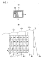
- [
Fig. 1] Fig. 1(a) is a perspective view showing the entire structure of an autostereoscopic display apparatus according to an embodiment of the present invention, andFig. 1(b) is an enlarged plan view of an area ME ofFig. 1(a) . - [
Fig. 2] Fig. 2 is a plan view showingcolor pixels 13 positioned around lens boundaries BL1 to BL3, andmagnified color pixels 23 displayed through acylindrical lens 12. - [
Fig. 3] Fig. 3 is a plan view showing a two-dimensional image without a parallax while simulating the case in which only color pixels of R (red) are lighted at maximum luminance, and color pixels of G (green) and B (blue) are lighted at minimum luminance.Fig. 3(a) shows the case in which px, L and θ do not fulfill the formula (1), andFig. 3(b) shows the case in which px, L and θ fulfill the formula (1). - [
Fig. 4] Fig. 4(a) is a plan view showing an arrangement example ofmagnified color pixels 23 when a horizontal pixel pitch px, a lens pitch L and an inclined angle θ fulfill only the formula (1), andFig. 4(b) is a plan view showing an arrangement example of themagnified color pixels 23 when the horizontal pixel pitch px, the lens pitch L and the inclined angle θ fulfill both the formula (1) and the formula (2). - [
Fig. 5] Fig. 5 is a plan view showing the case in whichcolor pixels 23 of each color magnified by cylindrical lenses are connected to each other in an oblique direction and visually recognized with periodicity. - Hereinafter, an embodiment of the present invention will be described with reference to the drawings. Note that the same elements in the figures are indicated by the same reference numerals.
- A structure of an autostereoscopic display apparatus according to the embodiment of the present invention will be described with reference to
Fig. 1(a) and Fig. 1(b) . The autostereoscopic display apparatus according to the embodiment of the present invention includes adisplay 11 in whichcolor pixels 13 are arranged at a predetermined pitch in a vertical direction VL and in a horizontal direction, respectively, and alenticular sheet 14 provided on a display surface of thedisplay 11. Thelenticular sheet 14 includes pluralcylindrical lenses color pixels 13 are visually recognized via the pluralcylindrical lenses 12. Boundaries BL1 to BL4 of thecylindrical lenses 12 are parallel to each other and inclined with respect to the vertical direction VL of thedisplay 11. The inclined angle is defined as "θ". - The plural rectangular shapes arranged in the vertical direction and in the horizontal direction, respectively, in
Fig. 1(b) show thecolor pixels 13 of thedisplay 11. In thedisplay 11, thecolor pixels 13 of three different colors of R (red), G (green) and B (blue) are periodically arranged in the horizontal direction, and the color pixels of each color are arranged in the vertical direction. Here, a lens pitch perpendicular to the boundaries BL1 to BL4 of the cylindrical lenses 12 (hereinafter, simply referred to as "a lens pitch") is defined as "L". Similarly, a pixel pitch of eachcolor pixel 13 in the horizontal direction (hereinafter, referred to as "a horizontal pixel pitch") is defined as "px", and a pixel pitch of eachcolor pixel 13 in the vertical direction (hereinafter, referred to as "a vertical pixel pitch") is defined as "py". Although the following description employs the definition of py/px=3, py/px may be other numbers other than 3. For example, the horizontal pixel pitch px and the vertical pixel pitch py of thedisplay 11 are defined as px=0.1 mm and py=0.3 mm, respectively. Thecylindrical lenses - When the
color pixels 13 of thedisplay 11 are viewed through thecylindrical lenses 12 in a predetermined direction, only thecolor pixels 13 equally distant from the boundaries BL1 and BL2 of thecylindrical lenses 12 are visually magnified. The distance of thevisible color pixels 13 from boundaries bl1 and bl2 varies depending on the direction to be viewed.Visible color pixels 23 are displayed while being magnified to the same size as the lens pitch L in the direction (power direction) of the lens pitch L of thecylindrical lenses 12. In particular, when all the color pixels are lighted at maximum luminance (white image), thecolor pixels 23 are visually magnified in a square shape of px/sinθ and L in the respective parallel and vertical directions to the boundaries BL1 and BL2, as shown inFig. 2 . - In this case, when the horizontal pixel pitch px, the lens pitch L and the inclined angle θ fulfill the formula (1), the
color pixels 23 of the same color of respective R (red), G (green) and B (blue) are arranged into approximately a delta sequence without being connected to each other. As a result, a two-dimensional image having a high resolution effect can be achieved. - In particular, when the lens pitch L is large, the
color pixels 23 are magnified because of the magnification effect of thecylindrical lenses 12. As a result, each of thecolor pixels 23 of R, G and B tends to be easily recognized. However, by defining px, L and θ by the formula (1), thecolor pixels 23 of the same color of thedisplay 11 visually recognized through thecylindrical lenses 12 are arranged into a delta sequence. Accordingly, a two-dimensional image with a high resolution effect can be achieved. -


- As an example, the inclined angle θ and the lens pitch L are set to θ=11.77° and L=0.779 mm, respectively. In this case, the formula (1) is fulfilled when m is 3. Therefore, the
color pixels 23 of the same color magnified and displayed through thecylindrical lenses 12 are arranged in a similar state to the delta sequence. Accordingly, an image with a high resolution effect can be achieved even when the color pixels are magnified because of the magnification effect of the lenses. -
Fig. 3 is a two-dimensional image without a parallax simulating the case in which only thecolor pixels 13 of R (red) are lighted at maximum luminance, and thecolor pixels 13 of respective G (green) and B (blue) are lighted at minimum luminance.Fig. 3(a) shows a two-dimensional image when using lenticular lenses of θ=11.77° and L=0.664 mm as an example of the case in which px, L and θ do not fulfill the formula (1), that is, there is no m to fulfill the formula (1). It is recognized that thecolor pixels 23 of the same color (in this case, red only) magnified due to the magnification effect of the lenses are connected to each other and therefore, the arrangement of thecolor pixels 23 of the same color shows periodicity. As a result, the resolution effect of the two-dimensional image is reduced. - Meanwhile,
Fig. 3(b) shows a two-dimensional image when using thecylindrical lenses 12 of θ=11.77° and L=0.779 mm as an example of the case in which px, L and θ fulfill the formula (1). In this case, m is 3, and px, L and θ are defined according to the formula (1). Although the lens pitch L is large, it can be seen that thecolor pixels 23 of the same color (in this case, only red) magnified due to the magnification effect of the lenses are separately arranged into a delta sequence. Accordingly, a two-dimensional image with a high resolution effect is obtained. Namely, even if thecolor pixels 23 are easily visually recognized individually because of the magnification effect of the lenses, a two-dimensional image with a relatively high resolution effect can be achieved. - Further, it is preferable that px, L and θ approximately fulfill the formula (2) in addition to the formula (1).
-

- As described above, according to the embodiment of the present invention, the following effects can be achieved.
- When the horizontal pixel pitch px, the lens pitch L and the inclined angle θ fulfill the formula (1), the
color pixels 23 of the same color of thedisplay 11 magnified through thecylindrical lenses 12 are not connected to each other but arranged into approximately a delta sequence. Therefore, a reduction in resolution when viewing thedisplay 11 through thecylindrical lenses 12 can be prevented. This is particularly effective in the case in which thecolor pixels 23 magnified through thecylindrical lenses 12 are easily visually recognized per color pixel unit, such as the case in which aninexpensive display 11 with a large pixel pitch of thecolor pixels 13 or adisplay 11 with low resolution is viewed, and the case in which asmall display 11 is viewed at close range. -
Fig. 4(a) is an arrangement example of the magnifiedcolor pixels 23 when the horizontal pixel pitch px, the lens pitch L and the inclined angle θ fulfill only the formula (1). In the case of fulfilling only the formula (1), thecolor pixels 23 of the same color are not connected to each other. However, acolor pixel 23a in thecylindrical lens 12 is located at an offset position from the middle between acolor pixel 23b and thecolor pixel 23c of the same color arranged in the samecylindrical lens 12 adjacent to thecylindrical lens 12 of thecolor pixel 23a. As a result, thecolor pixels 23 may show slight periodicity in the direction indicated by an arrow Ya. - Meanwhile,
Fig. 4(b) is an arrangement example of the magnifiedcolor pixels 23 when the horizontal pixel pitch px, the lens pitch L and the inclined angle θ fulfill both the formula (1) and the formula (2). In the case of fulfilling both the formula (1) and the formula (2), acolor pixel 23d in thecylindrical lens 12 is located exactly in the middle between thecolor pixel 23b and thecolor pixel 23c of the same color arranged in the samecylindrical lens 12 adjacent to thecylindrical lens 12 of thecolor pixel 23d. As a result, the arrangement of thecolor pixels 23 of the same color hardly shows periodicity, and in-plane uniformity of frequency characteristics is increased. Accordingly, a reduction in resolution can be further prevented not only because the magnifiedcolor pixels 23 of the same color of thedisplay 11 are not connected to each other, but also because thecolor pixels 23 of the same color can be most visually recognized without periodicity. - The present invention has been described by reference to one embodiment; however, it should be recognized that the present invention is not limited to the description and the drawings composing part of this disclosure. Various alternative embodiments, examples and operational techniques will be apparent to one of ordinary skill in the art from this disclosure.
- Although the liquid crystal display (LCD) panel and the color LCD display device were mentioned as an example of the
display 11, other displays such as a cathode-ray tube (CRT), a plasma display, an electronic paper and an EL (electroluminescence) display may be used. - The embodiment has been described in the case in which the
display 11 including thecolor pixels 13 of three colors of R, G and B that are periodically arranged in a horizontal direction is used. However, the present invention can also be applied to the case in which thecolor pixels 13 of four colors further including Y (yellow) or more kinds of colors are periodically arranged in a horizontal direction. - The present application is based on Japanese Patent Application No.
P2010-282027 (filed on December 17, 2010 - The autostereoscopic display apparatus according to the embodiment of the present invention includes the
display 11 in which thecolor pixels 13 of the different colors are periodically arranged in the horizontal direction and thecolor pixels 13 of the same color are arranged in the vertical direction, and a plurality of thecylindrical lenses 12a to 12c placed on thedisplay 11 and arranged parallel to each other, through which thecolor pixels 13 are magnified and observed. When the pixel pitch of thecolor pixels 13 in the horizontal direction HL is defined as px, the lens pitch of thecylindrical lenses 12a to 12c is defined as L, the inclined angle of the boundaries BL1 to BL3 of thecylindrical lenses 12a to 12c with respect to the vertical direction VL is defined as θ, and m is a positive integer, px, L and θ fulfill the formula (1) described above. Accordingly, a reduction in resolution when viewing thedisplay 11 through thecylindrical lenses 12a to 12c can be prevented. Thus, the autostereoscopic display apparatus according to the embodiment of the present invention is industrially applicable. -
- 11
- Display
- 12, 12a to 12c
- Cylindrical lens
- 13
- Color pixel
- 23
- Magnified color pixel
- BL1 to BL4
- Boundary
- HL
- Horizontal direction
- L
- Lens pitch
- px
- Horizontal pixel pitch (pixel pitch in horizontal direction)
- py
- Vertical pixel pitch (pixel pitch in vertical direction)
- VL
- Vertical direction
- θ
- Inclined angle
Claims (2)
- An autostereoscopic display apparatus, comprising:a display in which color pixels of different colors are periodically arranged in a horizontal direction and color pixels of an identical color are arranged in a vertical direction; anda plurality of cylindrical lenses placed on the display and arranged parallel to each other, through which the color pixels are magnified and observed,wherein when a pixel pitch of the color pixels in the horizontal direction is defined as px, a lens pitch of the cylindrical lenses is defined as L, an inclined angle of boundaries of the cylindrical lenses with respect to the vertical direction is defined as θ, and m is a positive integer, the px, L and θ fulfill the formula (1).

- The autostereoscopic display apparatus according to claim 1, wherein the px, L and θ fulfill the formula (2).

Applications Claiming Priority (2)
| Application Number | Priority Date | Filing Date | Title |
|---|---|---|---|
| JP2010282027A JP5170230B2 (en) | 2010-12-17 | 2010-12-17 | Autostereoscopic display device |
| PCT/JP2011/076770 WO2012081362A1 (en) | 2010-12-17 | 2011-11-21 | Naked-eye stereoscopic display device |
Publications (2)
| Publication Number | Publication Date |
|---|---|
| EP2653905A1 true EP2653905A1 (en) | 2013-10-23 |
| EP2653905A4 EP2653905A4 (en) | 2014-06-25 |
Family
ID=46244475
Family Applications (1)
| Application Number | Title | Priority Date | Filing Date |
|---|---|---|---|
| EP11849216.4A Withdrawn EP2653905A4 (en) | 2010-12-17 | 2011-11-21 | Naked-eye stereoscopic display device |
Country Status (5)
| Country | Link |
|---|---|
| US (1) | US20130208356A1 (en) |
| EP (1) | EP2653905A4 (en) |
| JP (1) | JP5170230B2 (en) |
| CN (1) | CN103430082A (en) |
| WO (1) | WO2012081362A1 (en) |
Families Citing this family (10)
| Publication number | Priority date | Publication date | Assignee | Title |
|---|---|---|---|---|
| CN104429065B (en) * | 2012-07-18 | 2017-03-15 | 皇家飞利浦有限公司 | Autostereoscopic lenticular display device |
| WO2014085290A1 (en) * | 2012-11-30 | 2014-06-05 | Lumenco, Llc | Slant lens interlacing |
| US9052518B2 (en) | 2012-11-30 | 2015-06-09 | Lumenco, Llc | Slant lens interlacing with linearly arranged sets of lenses |
| JP2015084079A (en) | 2013-09-20 | 2015-04-30 | パナソニックIpマネジメント株式会社 | Image display device |
| WO2016102338A1 (en) | 2014-12-24 | 2016-06-30 | Koninklijke Philips N.V. | Autostereoscopic display device |
| JP6456189B2 (en) | 2015-02-27 | 2019-01-23 | 国立研究開発法人情報通信研究機構 | Stereoscopic image display device |
| US10182224B2 (en) * | 2015-08-31 | 2019-01-15 | Theia Limited | Method for creating 3D image |
| CN112635510B (en) * | 2019-09-24 | 2024-08-02 | 新谱光科技股份有限公司 | Light-emitting panel for naked-eye stereoscopic display device with reduced moiré and manufacturing method thereof |
| KR102880683B1 (en) * | 2019-11-05 | 2025-11-06 | 삼성디스플레이 주식회사 | Display module and display device having the same |
| CN115047645B (en) * | 2022-05-20 | 2024-04-19 | 北京芯海视界三维科技有限公司 | Display screen and display device |
Family Cites Families (6)
| Publication number | Priority date | Publication date | Assignee | Title |
|---|---|---|---|---|
| JP3885077B2 (en) * | 2004-03-26 | 2007-02-21 | 独立行政法人科学技術振興機構 | 3D display |
| PL3035682T3 (en) * | 2005-04-29 | 2019-09-30 | Koninklijke Philips N.V. | A stereoscopic display apparatus |
| JP2008228199A (en) * | 2007-03-15 | 2008-09-25 | Toshiba Corp | Stereoscopic image display device, stereoscopic image display method, and structure of stereoscopic image data |
| JP4561794B2 (en) * | 2007-08-22 | 2010-10-13 | ソニー株式会社 | Aerial image display device |
| CN102257828B (en) * | 2008-12-18 | 2015-04-01 | 皇家飞利浦电子股份有限公司 | Autostereoscopic display device |
| JP5521380B2 (en) * | 2009-04-13 | 2014-06-11 | ソニー株式会社 | 3D display device |
-
2010
- 2010-12-17 JP JP2010282027A patent/JP5170230B2/en active Active
-
2011
- 2011-11-21 WO PCT/JP2011/076770 patent/WO2012081362A1/en not_active Ceased
- 2011-11-21 EP EP11849216.4A patent/EP2653905A4/en not_active Withdrawn
- 2011-11-21 CN CN2011800584604A patent/CN103430082A/en active Pending
-
2013
- 2013-03-15 US US13/837,930 patent/US20130208356A1/en not_active Abandoned
Also Published As
| Publication number | Publication date |
|---|---|
| EP2653905A4 (en) | 2014-06-25 |
| JP5170230B2 (en) | 2013-03-27 |
| JP2012128351A (en) | 2012-07-05 |
| CN103430082A (en) | 2013-12-04 |
| US20130208356A1 (en) | 2013-08-15 |
| WO2012081362A1 (en) | 2012-06-21 |
Similar Documents
| Publication | Publication Date | Title |
|---|---|---|
| US20130208356A1 (en) | Autostereoscopic display apparatus | |
| US8384772B2 (en) | Three-dimensional image display device and three-dimensional image display method | |
| KR100658545B1 (en) | Apparatus for reproducing stereo-scopic picture | |
| US8953241B2 (en) | Autostereoscopic display apparatus and method | |
| US9110298B2 (en) | Naked-eye stereoscopic display apparatus | |
| US8711478B2 (en) | Stereoscopic display | |
| CN101093630B (en) | 3D image display device | |
| CN102630022B (en) | Three-dimensional display apparatus and three-dimensional video display method | |
| US9964671B2 (en) | Display substrate, display panel, and stereoscopic display device | |
| US20130271510A1 (en) | Autostereoscopic display apparatus | |
| EP3249450B1 (en) | Substrate, grating and display panel | |
| CN105572886A (en) | Three-dimensional display device | |
| JP2012078696A (en) | Naked eye stereoscopic display device | |
| US11729368B2 (en) | Autostereoscopic display | |
| US11194172B2 (en) | Display device and display method | |
| KR101489990B1 (en) | 3d image display device | |
| EP3633439B1 (en) | Display panel, and 3d display device and 3d head up display (hud) device using the display panel | |
| US10264244B2 (en) | Display panel and a display driving method thereof, a display driving device and a display device | |
| KR20140041102A (en) | Display panel and display apparatus having the same | |
| JP2012212079A (en) | Display device | |
| KR20130028259A (en) | 3-dimensional display device | |
| CN212391679U (en) | 3D display device based on gradient pitch rectangular pinhole array | |
| JP2006091642A (en) | Video display device | |
| JP2004140700A (en) | Method and apparatus for displaying video | |
| EP2469864A2 (en) | Image processing apparatus |
Legal Events
| Date | Code | Title | Description |
|---|---|---|---|
| PUAI | Public reference made under article 153(3) epc to a published international application that has entered the european phase |
Free format text: ORIGINAL CODE: 0009012 |
|
| 17P | Request for examination filed |
Effective date: 20130617 |
|
| AK | Designated contracting states |
Kind code of ref document: A1 Designated state(s): AL AT BE BG CH CY CZ DE DK EE ES FI FR GB GR HR HU IE IS IT LI LT LU LV MC MK MT NL NO PL PT RO RS SE SI SK SM TR |
|
| DAX | Request for extension of the european patent (deleted) | ||
| A4 | Supplementary search report drawn up and despatched |
Effective date: 20140522 |
|
| RIC1 | Information provided on ipc code assigned before grant |
Ipc: G02B 27/22 20060101AFI20140516BHEP Ipc: H04N 13/04 20060101ALI20140516BHEP Ipc: G03B 35/24 20060101ALI20140516BHEP |
|
| STAA | Information on the status of an ep patent application or granted ep patent |
Free format text: STATUS: THE APPLICATION IS DEEMED TO BE WITHDRAWN |
|
| 18D | Application deemed to be withdrawn |
Effective date: 20141223 |