EP2653866B1 - Filter test strip - Google Patents
Filter test strip Download PDFInfo
- Publication number
- EP2653866B1 EP2653866B1 EP13155165.7A EP13155165A EP2653866B1 EP 2653866 B1 EP2653866 B1 EP 2653866B1 EP 13155165 A EP13155165 A EP 13155165A EP 2653866 B1 EP2653866 B1 EP 2653866B1
- Authority
- EP
- European Patent Office
- Prior art keywords
- filter
- layer
- cotton
- passage
- specimen
- Prior art date
- Legal status (The legal status is an assumption and is not a legal conclusion. Google has not performed a legal analysis and makes no representation as to the accuracy of the status listed.)
- Not-in-force
Links
- 229920000742 Cotton Polymers 0.000 claims description 74
- 239000007788 liquid Substances 0.000 claims description 20
- 239000000853 adhesive Substances 0.000 claims description 9
- 230000001070 adhesive effect Effects 0.000 claims description 9
- 239000000758 substrate Substances 0.000 claims description 4
- 210000000601 blood cell Anatomy 0.000 description 8
- 210000002381 plasma Anatomy 0.000 description 6
- 210000004369 blood Anatomy 0.000 description 5
- 239000008280 blood Substances 0.000 description 5
- HVYWMOMLDIMFJA-DPAQBDIFSA-N cholesterol Chemical compound C1C=C2C[C@@H](O)CC[C@]2(C)[C@@H]2[C@@H]1[C@@H]1CC[C@H]([C@H](C)CCCC(C)C)[C@@]1(C)CC2 HVYWMOMLDIMFJA-DPAQBDIFSA-N 0.000 description 2
- 238000007599 discharging Methods 0.000 description 2
- 239000011148 porous material Substances 0.000 description 2
- LEHOTFFKMJEONL-UHFFFAOYSA-N Uric Acid Chemical compound N1C(=O)NC(=O)C2=C1NC(=O)N2 LEHOTFFKMJEONL-UHFFFAOYSA-N 0.000 description 1
- TVWHNULVHGKJHS-UHFFFAOYSA-N Uric acid Natural products N1C(=O)NC(=O)C2NC(=O)NC21 TVWHNULVHGKJHS-UHFFFAOYSA-N 0.000 description 1
- 235000012000 cholesterol Nutrition 0.000 description 1
- 230000000694 effects Effects 0.000 description 1
- 230000035945 sensitivity Effects 0.000 description 1
- 210000002966 serum Anatomy 0.000 description 1
- 229940116269 uric acid Drugs 0.000 description 1
Images



Classifications
-
- G—PHYSICS
- G01—MEASURING; TESTING
- G01N—INVESTIGATING OR ANALYSING MATERIALS BY DETERMINING THEIR CHEMICAL OR PHYSICAL PROPERTIES
- G01N1/00—Sampling; Preparing specimens for investigation
- G01N1/28—Preparing specimens for investigation including physical details of (bio-)chemical methods covered elsewhere, e.g. G01N33/50, C12Q
- G01N1/34—Purifying; Cleaning
-
- G—PHYSICS
- G01—MEASURING; TESTING
- G01N—INVESTIGATING OR ANALYSING MATERIALS BY DETERMINING THEIR CHEMICAL OR PHYSICAL PROPERTIES
- G01N33/00—Investigating or analysing materials by specific methods not covered by groups G01N1/00 - G01N31/00
- G01N33/48—Biological material, e.g. blood, urine; Haemocytometers
- G01N33/50—Chemical analysis of biological material, e.g. blood, urine; Testing involving biospecific ligand binding methods; Immunological testing
- G01N33/52—Use of compounds or compositions for colorimetric, spectrophotometric or fluorometric investigation, e.g. use of reagent paper and including single- and multilayer analytical elements
- G01N33/525—Multi-layer analytical elements
-
- B—PERFORMING OPERATIONS; TRANSPORTING
- B01—PHYSICAL OR CHEMICAL PROCESSES OR APPARATUS IN GENERAL
- B01L—CHEMICAL OR PHYSICAL LABORATORY APPARATUS FOR GENERAL USE
- B01L2300/00—Additional constructional details
- B01L2300/06—Auxiliary integrated devices, integrated components
- B01L2300/0681—Filter
-
- B—PERFORMING OPERATIONS; TRANSPORTING
- B01—PHYSICAL OR CHEMICAL PROCESSES OR APPARATUS IN GENERAL
- B01L—CHEMICAL OR PHYSICAL LABORATORY APPARATUS FOR GENERAL USE
- B01L2300/00—Additional constructional details
- B01L2300/08—Geometry, shape and general structure
- B01L2300/0809—Geometry, shape and general structure rectangular shaped
- B01L2300/0816—Cards, e.g. flat sample carriers usually with flow in two horizontal directions
-
- B—PERFORMING OPERATIONS; TRANSPORTING
- B01—PHYSICAL OR CHEMICAL PROCESSES OR APPARATUS IN GENERAL
- B01L—CHEMICAL OR PHYSICAL LABORATORY APPARATUS FOR GENERAL USE
- B01L2300/00—Additional constructional details
- B01L2300/08—Geometry, shape and general structure
- B01L2300/0809—Geometry, shape and general structure rectangular shaped
- B01L2300/0825—Test strips
-
- B—PERFORMING OPERATIONS; TRANSPORTING
- B01—PHYSICAL OR CHEMICAL PROCESSES OR APPARATUS IN GENERAL
- B01L—CHEMICAL OR PHYSICAL LABORATORY APPARATUS FOR GENERAL USE
- B01L2300/00—Additional constructional details
- B01L2300/08—Geometry, shape and general structure
- B01L2300/0887—Laminated structure
-
- G—PHYSICS
- G01—MEASURING; TESTING
- G01N—INVESTIGATING OR ANALYSING MATERIALS BY DETERMINING THEIR CHEMICAL OR PHYSICAL PROPERTIES
- G01N15/00—Investigating characteristics of particles; Investigating permeability, pore-volume or surface-area of porous materials
- G01N15/01—Investigating characteristics of particles; Investigating permeability, pore-volume or surface-area of porous materials specially adapted for biological cells, e.g. blood cells
-
- G—PHYSICS
- G01—MEASURING; TESTING
- G01N—INVESTIGATING OR ANALYSING MATERIALS BY DETERMINING THEIR CHEMICAL OR PHYSICAL PROPERTIES
- G01N1/00—Sampling; Preparing specimens for investigation
- G01N1/28—Preparing specimens for investigation including physical details of (bio-)chemical methods covered elsewhere, e.g. G01N33/50, C12Q
- G01N1/40—Concentrating samples
- G01N1/4077—Concentrating samples by other techniques involving separation of suspended solids
- G01N2001/4088—Concentrating samples by other techniques involving separation of suspended solids filtration
-
- G—PHYSICS
- G01—MEASURING; TESTING
- G01N—INVESTIGATING OR ANALYSING MATERIALS BY DETERMINING THEIR CHEMICAL OR PHYSICAL PROPERTIES
- G01N2458/00—Labels used in chemical analysis of biological material
-
- G—PHYSICS
- G01—MEASURING; TESTING
- G01N—INVESTIGATING OR ANALYSING MATERIALS BY DETERMINING THEIR CHEMICAL OR PHYSICAL PROPERTIES
- G01N27/00—Investigating or analysing materials by the use of electric, electrochemical, or magnetic means
- G01N27/26—Investigating or analysing materials by the use of electric, electrochemical, or magnetic means by investigating electrochemical variables; by using electrolysis or electrophoresis
- G01N27/416—Systems
- G01N27/42—Measuring deposition or liberation of materials from an electrolyte; Coulometry, i.e. measuring coulomb-equivalent of material in an electrolyte
-
- G—PHYSICS
- G01—MEASURING; TESTING
- G01N—INVESTIGATING OR ANALYSING MATERIALS BY DETERMINING THEIR CHEMICAL OR PHYSICAL PROPERTIES
- G01N27/00—Investigating or analysing materials by the use of electric, electrochemical, or magnetic means
- G01N27/26—Investigating or analysing materials by the use of electric, electrochemical, or magnetic means by investigating electrochemical variables; by using electrolysis or electrophoresis
- G01N27/416—Systems
- G01N27/42—Measuring deposition or liberation of materials from an electrolyte; Coulometry, i.e. measuring coulomb-equivalent of material in an electrolyte
- G01N27/423—Coulometry
Definitions
- the present invention relates to a filter test strip and particularly to a filter structure for a filter test strip.
- a conventional filter test strip includes a filter cotton holding layer 1, a cotton bonding layer 2 and a test element 7.
- the filter cotton holding layer 1 and cotton bonding layer 2 are bonded by an adhesive 3 between them.
- the filter cotton holding layer 1 has a filter cotton 4 to filter blood 5 and remove blood cells to separate the blood cells and plasma, and allow only the plasma to pass through filter cotton to be captured.
- the plasma enters the test element 7 to be tested to get physiological data such as cholesterol, uric acid and the like.
- the filter cotton 4 is made of porous material to filter the blood cells of the blood 5 and separate the blood cells and plasma.
- the porous material tends to form uneven surfaces and gaps at the borders.
- gaps 6 are inevitably formed between the filter cotton 4 and filter cotton holding layer 1 that easily let the and blood cells to percolate through.
- the adhesive 3, the filter cotton 4 and cotton bonding layer 2 cannot form a tight bonding among them, some of the blood cells in the blood 5 tend to pass through the filter cotton 4 through the gaps 6 and between the filter cotton 4 and cotton bonding layer 2 to blend with the filtered blood 5 containing only the plasma.
- the primary object of the present invention is to provide a filter structure that can fully filter a specimen in liquid to meet use requirements.
- the present invention provides a filter test strip to filter and test a specimen in liquid according to the claims. It includes a test element and a specimen filter assembly.
- the specimen filter assembly is located on the test element and includes at least one filter cotton holding layer, at least one filter cotton layer and at least one cotton bonding layer.
- the filter cotton holding layer has a filter channel to allow the specimen in liquid to pass through.
- the filter cotton layer fills the corresponding filter channel.
- a gap is formed between the filter cotton holding layer and filter cotton layer.
- the cotton bonding layer is located below the filter cotton holding layer and bonded to the test element via an adhesive which fully covers the circumference of the filter channel and masks the gap between the filter cotton holding layer and filter cotton layer.
- the present invention aims to provide a filter test strip to filter and test a specimen in liquid 10. It includes a test element 20 and a specimen filter assembly 30.
- the specimen filter assembly 30 is located on the test element 20, and includes at least one filter cotton holding layer 31, at least one filter cotton layer 32 and at least one cotton bonding layer 33.
- the filter cotton holding layer 31 has a filter channel 311 to allow the specimen in liquid 10 to pass through.
- the filter cotton layer 32 fills the corresponding filter channel 311.
- a gap 40 is formed between the filter cotton holding layer 31 and filter cotton layer 32. The gap 40 shown in the drawing is enlarged to facilitate discussion, and not the actual size.
- the cotton bonding layer 33 is located below the filter cotton holding layer 31 via an adhesive 50 and bonded to the test element 20.
- the adhesive 50 on the cotton bonding layer 33 fully covers the circumference of the filter channel 311 and masks the gap 40 between the filter cotton holding layer 31 and filter cotton layer 32.
- the filter cotton holding layer 31, filter cotton layer 32 and cotton bonding layer 33 have respectively two sets as an example for discussion. It also includes a cotton press layer 60 and an upper lid 70 that sequentially cover the specimen filter assembly 30 and mask the filter channel 311 to protect the specimen filter assembly 30.
- the cotton press layer 60 has a passage 61 to receive the specimen in liquid 10 from outside and communicate with the filter channel 311.
- the passage 61 transversely runs through the cotton press layer 60 to form an air outlet 62 for discharging air 90 and a specimen inlet 63 for receiving the specimen in liquid 10.
- the air outlet 62 and specimen inlet 63 can be switched in positions as desired to suit users' hand using habits.
- the invention can also include a passage layer 80 located between the cotton press layer 60 and upper lid 70.
- the passage layer 80 has an ancillary passage 81 corresponding to the passage 61 and formed at an area greater than that of the passage 61.
- the ancillary passage 81 also transversely runs through the passage layer 80 to form an ancillary air outlet 82 for discharging the air 90 and an ancillary specimen inlet 83 for receiving the specimen in liquid 10.
- the ancillary specimen inlet 83 can increase space for the specimen in liquid 10 to enter, and the ancillary air outlet 82 can improve air discharge effect so that entry of the specimen in liquid 10 is easier to enhance test sensitivity.
- the test element 20 can include a substrate 21 and an electrode 22 formed on the substrate 21 to contact the filter channel 311.
- FIGS. 5 , 6A and 6B for a second embodiment of the invention. It differs from the first embodiment by the cotton press layer 60A having a passage 61A to receive the specimen in liquid 10 from outside.
- the passage 61A communicates with the filter channel 311 and has a specimen inlet 63 to receive the specimen in liquid 10.
- the filter cotton holding layer 31 includes an output channel 312 communicating with outside and the filter channel 311.
- the output channel 312 can discharge the air 90.
- a passage layer 80A also is provided between the cotton press layer 60A and upper lid 70.
- the passage layer 80A also has an ancillary passage 81A corresponding to the passage 61A and formed at an area greater than that of the passage 61A.
- the ancillary passage 81A also has an ancillary specimen inlet 83 to receive the specimen in liquid 10. Through the ancillary specimen inlet 83 and output channel 312, a structure with liquid entry at the upper side and air discharge at the lower side is formed to make entry of the specimen in liquid 10 easier.
- the specimen in liquid can be prevented from seeping out through gap with passing through the filter cotton layer, thereby the specimen in liquid can fully be filtered by the filter cotton layer to improve test accuracy and meet use requirements.
Landscapes
- Health & Medical Sciences (AREA)
- Life Sciences & Earth Sciences (AREA)
- Immunology (AREA)
- Engineering & Computer Science (AREA)
- Biomedical Technology (AREA)
- Molecular Biology (AREA)
- Chemical & Material Sciences (AREA)
- Hematology (AREA)
- General Physics & Mathematics (AREA)
- General Health & Medical Sciences (AREA)
- Biochemistry (AREA)
- Analytical Chemistry (AREA)
- Pathology (AREA)
- Physics & Mathematics (AREA)
- Urology & Nephrology (AREA)
- Cell Biology (AREA)
- Microbiology (AREA)
- Biotechnology (AREA)
- Food Science & Technology (AREA)
- Medicinal Chemistry (AREA)
- Sampling And Sample Adjustment (AREA)
- Investigating Or Analysing Biological Materials (AREA)
Description
- The present invention relates to a filter test strip and particularly to a filter structure for a filter test strip.
- Please refer to
FIG. 1 , a conventional filter test strip includes a filtercotton holding layer 1, acotton bonding layer 2 and a test element 7. The filtercotton holding layer 1 andcotton bonding layer 2 are bonded by an adhesive 3 between them. The filtercotton holding layer 1 has afilter cotton 4 to filterblood 5 and remove blood cells to separate the blood cells and plasma, and allow only the plasma to pass through filter cotton to be captured. The plasma enters the test element 7 to be tested to get physiological data such as cholesterol, uric acid and the like. - In the aforesaid conventional structure, the
filter cotton 4 is made of porous material to filter the blood cells of theblood 5 and separate the blood cells and plasma. However, the porous material tends to form uneven surfaces and gaps at the borders. When thefilter cotton 4 is held in the filtercotton holding layer 1gaps 6 are inevitably formed between thefilter cotton 4 and filtercotton holding layer 1 that easily let the and blood cells to percolate through. Moreover, because the adhesive 3, thefilter cotton 4 andcotton bonding layer 2 cannot form a tight bonding among them, some of the blood cells in theblood 5 tend to pass through thefilter cotton 4 through thegaps 6 and between thefilter cotton 4 andcotton bonding layer 2 to blend with the filteredblood 5 containing only the plasma. In other words, in the conventional structure thefilter cotton 4 cannot fully filter out the blood cells in theblood 5. It contains residual blood cells during the test that affect test accuracy, thus cannot fully meet use requirements. The documentsEP 1477 804 A1 ,EP 1182 456 A2 ,WO 01/38873 A2 WO 2012/174144A1 disclose instruments for separating plasma or serum. - Therefore the primary object of the present invention is to provide a filter structure that can fully filter a specimen in liquid to meet use requirements.
- To achieve the foregoing object, the present invention provides a filter test strip to filter and test a specimen in liquid according to the claims. It includes a test element and a specimen filter assembly. The specimen filter assembly is located on the test element and includes at least one filter cotton holding layer, at least one filter cotton layer and at least one cotton bonding layer. The filter cotton holding layer has a filter channel to allow the specimen in liquid to pass through. The filter cotton layer fills the corresponding filter channel. A gap is formed between the filter cotton holding layer and filter cotton layer. The cotton bonding layer is located below the filter cotton holding layer and bonded to the test element via an adhesive which fully covers the circumference of the filter channel and masks the gap between the filter cotton holding layer and filter cotton layer.
- By means of the structure set forth above, with the adhesive fully covering the circumference of the filter channel to mask the gap between the filter cotton holding layer and filter cotton layer, the specimen in liquid can fully pass through the filter cotton layer, hence test accuracy can be improved to meet use requirements.
- The foregoing, as well as additional objects, features and advantages of the invention will be more readily apparent from the following detailed description, which proceeds with reference to the accompanying drawings.
-
-
FIG. 1 is a schematic view of a conventional filter test strip. -
FIG. 2 is a schematic view of the filter structure of the filter test strip of the invention. -
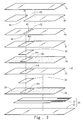
FIG. 3 is an exploded view of a first embodiment of the invention. -
FIG. 4A is a front view of the first embodiment of the invention. -
FIG. 4B is a cross section taken online 4B-4B inFIG. 4A . -
FIG 5 is an exploded view of a second embodiment of the invention. -
FIG. 6A is a front view of the second embodiment of the invention. -
FIG. 6B is a cross section taken online 6B-6B inFIG. 6A . - Please refer to
FIG. 2 , the present invention aims to provide a filter test strip to filter and test a specimen inliquid 10. It includes atest element 20 and aspecimen filter assembly 30. Thespecimen filter assembly 30 is located on thetest element 20, and includes at least one filtercotton holding layer 31, at least onefilter cotton layer 32 and at least onecotton bonding layer 33. In the drawing each of the aforesaid layers is depicted by one set as an example for discussion. The filtercotton holding layer 31 has afilter channel 311 to allow the specimen inliquid 10 to pass through. Thefilter cotton layer 32 fills thecorresponding filter channel 311. Agap 40 is formed between the filtercotton holding layer 31 andfilter cotton layer 32. Thegap 40 shown in the drawing is enlarged to facilitate discussion, and not the actual size. Thecotton bonding layer 33 is located below the filtercotton holding layer 31 via an adhesive 50 and bonded to thetest element 20. Theadhesive 50 on thecotton bonding layer 33 fully covers the circumference of thefilter channel 311 and masks thegap 40 between the filtercotton holding layer 31 andfilter cotton layer 32. - Please refer to
FIGS. 3 ,4A and4B for a first embodiment of the invention. In this embodiment, the filtercotton holding layer 31,filter cotton layer 32 andcotton bonding layer 33 have respectively two sets as an example for discussion. It also includes acotton press layer 60 and anupper lid 70 that sequentially cover thespecimen filter assembly 30 and mask thefilter channel 311 to protect thespecimen filter assembly 30. Thecotton press layer 60 has apassage 61 to receive the specimen inliquid 10 from outside and communicate with thefilter channel 311. Thepassage 61 transversely runs through thecotton press layer 60 to form anair outlet 62 for dischargingair 90 and aspecimen inlet 63 for receiving the specimen inliquid 10. In practice, theair outlet 62 andspecimen inlet 63 can be switched in positions as desired to suit users' hand using habits. - The invention, according to another embodiment, can also include a
passage layer 80 located between thecotton press layer 60 andupper lid 70. Thepassage layer 80 has anancillary passage 81 corresponding to thepassage 61 and formed at an area greater than that of thepassage 61. Theancillary passage 81 also transversely runs through thepassage layer 80 to form anancillary air outlet 82 for discharging theair 90 and anancillary specimen inlet 83 for receiving the specimen inliquid 10. Theancillary specimen inlet 83 can increase space for the specimen inliquid 10 to enter, and theancillary air outlet 82 can improve air discharge effect so that entry of the specimen inliquid 10 is easier to enhance test sensitivity. Thetest element 20 can include asubstrate 21 and anelectrode 22 formed on thesubstrate 21 to contact thefilter channel 311. - Please refer to
FIGS. 5 ,6A and6B for a second embodiment of the invention. It differs from the first embodiment by thecotton press layer 60A having apassage 61A to receive the specimen inliquid 10 from outside. Thepassage 61A communicates with thefilter channel 311 and has aspecimen inlet 63 to receive the specimen inliquid 10. The filtercotton holding layer 31 includes anoutput channel 312 communicating with outside and thefilter channel 311. Theoutput channel 312 can discharge theair 90. Similarly, apassage layer 80A also is provided between thecotton press layer 60A andupper lid 70. Thepassage layer 80A also has anancillary passage 81A corresponding to thepassage 61A and formed at an area greater than that of thepassage 61A. Theancillary passage 81A also has anancillary specimen inlet 83 to receive the specimen inliquid 10. Through theancillary specimen inlet 83 andoutput channel 312, a structure with liquid entry at the upper side and air discharge at the lower side is formed to make entry of the specimen inliquid 10 easier. - As a conclusion, in the invention, with the adhesive extended to fully cover the circumference of the filter channel and mask the gap between the filter cotton holding layer and filter cotton layer, the specimen in liquid can be prevented from seeping out through gap with passing through the filter cotton layer, thereby the specimen in liquid can fully be filtered by the filter cotton layer to improve test accuracy and meet use requirements.
Claims (7)
- A filter test strip to filter and test a specimen in liquid (10), comprising:a test element (20); anda specimen filter assembly (30) which is located on the test element (20) and includes:at least one filter cotton holding layer (31);at least one filter cotton layer (32); andat least one cotton bonding layer (33);wherein the filter cotton holding layer (31) includes a filter channel (311) to allow the specimen in liquid (10) to pass through and to hold the filter cotton layer (32) in the filter channel (311), wherein a gap (40) is formed between the filter cotton holding layer (31) and filter cotton layer (32), and the cotton bonding layer (33) is bonded to a lower side of the filter cotton holding layer (31) via an adhesive (50);characterized in thatthe adhesive (50) on the cotton bonding layer (33) fully covers a circumference of the filter cotton layer (32) and masks the gap (40) between the filter cotton holding layer (31) and filter cotton layer (32).
- The filter test strip of claim 1 further including a passage layer (80) located between the cotton press layer (60) and the upper lid (70), the passage layer (80) including an ancillary passage (81) formed at an area greater than that of the passage (61) and corresponding to the passage (61).
- The filter test strip of claim 2, wherein the ancillary passage (81) transversely runs through the passage layer (80) to form an ancillary air outlet (82) and an ancillary specimen inlet (83).
- The filter test strip of claims 1 to 3, wherein the test element (20) includes a substrate (21) and an electrode (22) formed on the substrate (21) to contact the filter channel (311).
- The filter test strip of claims 2 to 4, wherein the passage (61A) includes a specimen inlet (63), the filter cotton holding layer (31) including an output channel (312) communicating with the outside and the filter channel (311).
- The filter test strip of claim 5 further including a passage layer (80A) located between the cotton press layer (60A) and the upper lid (70), the passage layer (80A) including an ancillary passage (81A) formed at an area greater than that of the passage (61A) and corresponding to the passage (61A).
- The filter test strip of claim 6, wherein the ancillary passage (81A) including an ancillary specimen inlet (83).
Applications Claiming Priority (1)
| Application Number | Priority Date | Filing Date | Title |
|---|---|---|---|
| TW101207263U TWM441450U (en) | 2012-04-19 | 2012-04-19 | Filtering type test strip |
Publications (2)
| Publication Number | Publication Date |
|---|---|
| EP2653866A1 EP2653866A1 (en) | 2013-10-23 |
| EP2653866B1 true EP2653866B1 (en) | 2019-11-13 |
Family
ID=47717800
Family Applications (1)
| Application Number | Title | Priority Date | Filing Date |
|---|---|---|---|
| EP13155165.7A Not-in-force EP2653866B1 (en) | 2012-04-19 | 2013-02-14 | Filter test strip |
Country Status (4)
| Country | Link |
|---|---|
| US (1) | US9194777B2 (en) |
| EP (1) | EP2653866B1 (en) |
| HU (1) | HUE047300T2 (en) |
| TW (1) | TWM441450U (en) |
Families Citing this family (2)
| Publication number | Priority date | Publication date | Assignee | Title |
|---|---|---|---|---|
| KR102864157B1 (en) | 2019-07-16 | 2025-09-24 | 주식회사 엘지에너지솔루션 | Lithium secondary battery |
| CN113420813B (en) * | 2021-06-23 | 2023-11-28 | 北京市机械工业局技术开发研究所 | Diagnostic method for particulate matter filter cotton state of vehicle tail gas detection equipment |
Family Cites Families (8)
| Publication number | Priority date | Publication date | Assignee | Title |
|---|---|---|---|---|
| US5762770A (en) * | 1994-02-21 | 1998-06-09 | Boehringer Mannheim Corporation | Electrochemical biosensor test strip |
| US6670115B1 (en) * | 1999-11-24 | 2003-12-30 | Biotronic Technologies, Inc. | Devices and methods for detecting analytes using electrosensor having capture reagent |
| US6726818B2 (en) * | 2000-07-21 | 2004-04-27 | I-Sens, Inc. | Biosensors with porous chromatographic membranes |
| EP1477804A4 (en) * | 2002-02-27 | 2016-12-28 | Pfaff Medical Gmbh | Instrument for separating plasma or serum, method of collecting plasma or serum, method of separating plasma or serum, test carrier and glass fiber |
| US6942769B2 (en) * | 2003-08-05 | 2005-09-13 | Bt Medical Corp. | Electrochemical sensor strip with low porosity screen |
| US8012428B2 (en) * | 2008-10-30 | 2011-09-06 | Lifescan Scotland, Ltd. | Analytical test strip with minimal fill-error sample viewing window |
| KR101110561B1 (en) * | 2009-06-04 | 2012-02-15 | 주식회사 인포피아 | Bio sensor |
| AU2012271718A1 (en) * | 2011-06-16 | 2014-01-09 | Baylor Research Institute | Analysis of total homocysteine and methylmalonic acid in plasma by LC-MS/MS from a plasma separator device (PSD) |
-
2012
- 2012-04-19 TW TW101207263U patent/TWM441450U/en not_active IP Right Cessation
-
2013
- 2013-02-14 EP EP13155165.7A patent/EP2653866B1/en not_active Not-in-force
- 2013-02-14 HU HUE13155165A patent/HUE047300T2/en unknown
- 2013-02-19 US US13/770,704 patent/US9194777B2/en active Active
Non-Patent Citations (1)
| Title |
|---|
| None * |
Also Published As
| Publication number | Publication date |
|---|---|
| US20130280800A1 (en) | 2013-10-24 |
| TWM441450U (en) | 2012-11-21 |
| US9194777B2 (en) | 2015-11-24 |
| HUE047300T2 (en) | 2020-04-28 |
| EP2653866A1 (en) | 2013-10-23 |
Similar Documents
| Publication | Publication Date | Title |
|---|---|---|
| JP3574786B2 (en) | Cell and method for electrochemical analysis of a sample. | |
| US7998347B2 (en) | Suction filter for automatic transmission fluid | |
| US8845869B2 (en) | Electrochemical sensor strip | |
| US8857627B2 (en) | Blood processing filter | |
| US7738264B2 (en) | Devices and methods for protecting handheld electronic devices from electrostatic discharge | |
| WO2002010734A1 (en) | Biosensor | |
| CN102023744A (en) | Position detection apparatus | |
| WO2007044548A3 (en) | Fluid handling cassette system for body fluid analyzer | |
| CN104634832B (en) | CMOS MEMS capacitive humidity sensors and preparation method thereof | |
| EP2653866A1 (en) | Filter test strip | |
| EP3043165A1 (en) | Body fluid collector, body fluid container, and body fluid collection device | |
| DE50312674D1 (en) | Filter | |
| US8993913B2 (en) | Cover glass pressure button | |
| KR20160061645A (en) | Membrane filter container for cytology smear device | |
| WO2016106320A2 (en) | Foldable opposing sensor array | |
| US20160188072A1 (en) | Touch display panel | |
| US20210013475A1 (en) | Electrode assembly, secondary battery comprising the same, method for manufacturing secondary battery, and battery pack | |
| ITPD20080270A1 (en) | FILTERING SYSTEM WITH REPLACEABLE CARTRIDGE | |
| KR101409333B1 (en) | Collection vial for cytological diagnosis | |
| JP2025500710A (en) | Chips, grinders and their uses for lysing microorganisms | |
| CN107126753B (en) | Active micro-fluidic chip and whole blood filter equipment thereof | |
| CN202793889U (en) | A filter type test piece | |
| US20160067709A1 (en) | Micro-channel module | |
| CN207894939U (en) | A kind of immunochromatography reagent card | |
| KR101444281B1 (en) | Glucose measuring strip with separable lancet |
Legal Events
| Date | Code | Title | Description |
|---|---|---|---|
| PUAI | Public reference made under article 153(3) epc to a published international application that has entered the european phase |
Free format text: ORIGINAL CODE: 0009012 |
|
| AK | Designated contracting states |
Kind code of ref document: A1 Designated state(s): AL AT BE BG CH CY CZ DE DK EE ES FI FR GB GR HR HU IE IS IT LI LT LU LV MC MK MT NL NO PL PT RO RS SE SI SK SM TR |
|
| AX | Request for extension of the european patent |
Extension state: BA ME |
|
| 17P | Request for examination filed |
Effective date: 20140318 |
|
| RBV | Designated contracting states (corrected) |
Designated state(s): AL AT BE BG CH CY CZ DE DK EE ES FI FR GB GR HR HU IE IS IT LI LT LU LV MC MK MT NL NO PL PT RO RS SE SI SK SM TR |
|
| STAA | Information on the status of an ep patent application or granted ep patent |
Free format text: STATUS: EXAMINATION IS IN PROGRESS |
|
| 17Q | First examination report despatched |
Effective date: 20161122 |
|
| GRAP | Despatch of communication of intention to grant a patent |
Free format text: ORIGINAL CODE: EPIDOSNIGR1 |
|
| STAA | Information on the status of an ep patent application or granted ep patent |
Free format text: STATUS: GRANT OF PATENT IS INTENDED |
|
| INTG | Intention to grant announced |
Effective date: 20190704 |
|
| RIN1 | Information on inventor provided before grant (corrected) |
Inventor name: CHANG, YA-YUAN Inventor name: LAI, CHIN-SHAN Inventor name: YANG, CHIN-CHANG Inventor name: WU, KUN-LIEH |
|
| GRAS | Grant fee paid |
Free format text: ORIGINAL CODE: EPIDOSNIGR3 |
|
| GRAA | (expected) grant |
Free format text: ORIGINAL CODE: 0009210 |
|
| STAA | Information on the status of an ep patent application or granted ep patent |
Free format text: STATUS: THE PATENT HAS BEEN GRANTED |
|
| AK | Designated contracting states |
Kind code of ref document: B1 Designated state(s): AL AT BE BG CH CY CZ DE DK EE ES FI FR GB GR HR HU IE IS IT LI LT LU LV MC MK MT NL NO PL PT RO RS SE SI SK SM TR |
|
| REG | Reference to a national code |
Ref country code: CH Ref legal event code: EP Ref country code: AT Ref legal event code: REF Ref document number: 1202216 Country of ref document: AT Kind code of ref document: T Effective date: 20191115 |
|
| REG | Reference to a national code |
Ref country code: DE Ref legal event code: R096 Ref document number: 602013062782 Country of ref document: DE |
|
| REG | Reference to a national code |
Ref country code: IE Ref legal event code: FG4D |
|
| REG | Reference to a national code |
Ref country code: NL Ref legal event code: MP Effective date: 20191113 |
|
| REG | Reference to a national code |
Ref country code: LT Ref legal event code: MG4D |
|
| REG | Reference to a national code |
Ref country code: HU Ref legal event code: AG4A Ref document number: E047300 Country of ref document: HU |
|
| PG25 | Lapsed in a contracting state [announced via postgrant information from national office to epo] |
Ref country code: LT Free format text: LAPSE BECAUSE OF FAILURE TO SUBMIT A TRANSLATION OF THE DESCRIPTION OR TO PAY THE FEE WITHIN THE PRESCRIBED TIME-LIMIT Effective date: 20191113 Ref country code: NL Free format text: LAPSE BECAUSE OF FAILURE TO SUBMIT A TRANSLATION OF THE DESCRIPTION OR TO PAY THE FEE WITHIN THE PRESCRIBED TIME-LIMIT Effective date: 20191113 Ref country code: PL Free format text: LAPSE BECAUSE OF FAILURE TO SUBMIT A TRANSLATION OF THE DESCRIPTION OR TO PAY THE FEE WITHIN THE PRESCRIBED TIME-LIMIT Effective date: 20191113 Ref country code: SE Free format text: LAPSE BECAUSE OF FAILURE TO SUBMIT A TRANSLATION OF THE DESCRIPTION OR TO PAY THE FEE WITHIN THE PRESCRIBED TIME-LIMIT Effective date: 20191113 Ref country code: NO Free format text: LAPSE BECAUSE OF FAILURE TO SUBMIT A TRANSLATION OF THE DESCRIPTION OR TO PAY THE FEE WITHIN THE PRESCRIBED TIME-LIMIT Effective date: 20200213 Ref country code: LV Free format text: LAPSE BECAUSE OF FAILURE TO SUBMIT A TRANSLATION OF THE DESCRIPTION OR TO PAY THE FEE WITHIN THE PRESCRIBED TIME-LIMIT Effective date: 20191113 Ref country code: FI Free format text: LAPSE BECAUSE OF FAILURE TO SUBMIT A TRANSLATION OF THE DESCRIPTION OR TO PAY THE FEE WITHIN THE PRESCRIBED TIME-LIMIT Effective date: 20191113 Ref country code: BG Free format text: LAPSE BECAUSE OF FAILURE TO SUBMIT A TRANSLATION OF THE DESCRIPTION OR TO PAY THE FEE WITHIN THE PRESCRIBED TIME-LIMIT Effective date: 20200213 Ref country code: PT Free format text: LAPSE BECAUSE OF FAILURE TO SUBMIT A TRANSLATION OF THE DESCRIPTION OR TO PAY THE FEE WITHIN THE PRESCRIBED TIME-LIMIT Effective date: 20200313 Ref country code: ES Free format text: LAPSE BECAUSE OF FAILURE TO SUBMIT A TRANSLATION OF THE DESCRIPTION OR TO PAY THE FEE WITHIN THE PRESCRIBED TIME-LIMIT Effective date: 20191113 Ref country code: GR Free format text: LAPSE BECAUSE OF FAILURE TO SUBMIT A TRANSLATION OF THE DESCRIPTION OR TO PAY THE FEE WITHIN THE PRESCRIBED TIME-LIMIT Effective date: 20200214 |
|
| PG25 | Lapsed in a contracting state [announced via postgrant information from national office to epo] |
Ref country code: IS Free format text: LAPSE BECAUSE OF FAILURE TO SUBMIT A TRANSLATION OF THE DESCRIPTION OR TO PAY THE FEE WITHIN THE PRESCRIBED TIME-LIMIT Effective date: 20200313 Ref country code: HR Free format text: LAPSE BECAUSE OF FAILURE TO SUBMIT A TRANSLATION OF THE DESCRIPTION OR TO PAY THE FEE WITHIN THE PRESCRIBED TIME-LIMIT Effective date: 20191113 Ref country code: RS Free format text: LAPSE BECAUSE OF FAILURE TO SUBMIT A TRANSLATION OF THE DESCRIPTION OR TO PAY THE FEE WITHIN THE PRESCRIBED TIME-LIMIT Effective date: 20191113 |
|
| PG25 | Lapsed in a contracting state [announced via postgrant information from national office to epo] |
Ref country code: AL Free format text: LAPSE BECAUSE OF FAILURE TO SUBMIT A TRANSLATION OF THE DESCRIPTION OR TO PAY THE FEE WITHIN THE PRESCRIBED TIME-LIMIT Effective date: 20191113 |
|
| PG25 | Lapsed in a contracting state [announced via postgrant information from national office to epo] |
Ref country code: RO Free format text: LAPSE BECAUSE OF FAILURE TO SUBMIT A TRANSLATION OF THE DESCRIPTION OR TO PAY THE FEE WITHIN THE PRESCRIBED TIME-LIMIT Effective date: 20191113 Ref country code: EE Free format text: LAPSE BECAUSE OF FAILURE TO SUBMIT A TRANSLATION OF THE DESCRIPTION OR TO PAY THE FEE WITHIN THE PRESCRIBED TIME-LIMIT Effective date: 20191113 Ref country code: DK Free format text: LAPSE BECAUSE OF FAILURE TO SUBMIT A TRANSLATION OF THE DESCRIPTION OR TO PAY THE FEE WITHIN THE PRESCRIBED TIME-LIMIT Effective date: 20191113 |
|
| REG | Reference to a national code |
Ref country code: DE Ref legal event code: R097 Ref document number: 602013062782 Country of ref document: DE |
|
| REG | Reference to a national code |
Ref country code: AT Ref legal event code: MK05 Ref document number: 1202216 Country of ref document: AT Kind code of ref document: T Effective date: 20191113 |
|
| PG25 | Lapsed in a contracting state [announced via postgrant information from national office to epo] |
Ref country code: SM Free format text: LAPSE BECAUSE OF FAILURE TO SUBMIT A TRANSLATION OF THE DESCRIPTION OR TO PAY THE FEE WITHIN THE PRESCRIBED TIME-LIMIT Effective date: 20191113 Ref country code: SK Free format text: LAPSE BECAUSE OF FAILURE TO SUBMIT A TRANSLATION OF THE DESCRIPTION OR TO PAY THE FEE WITHIN THE PRESCRIBED TIME-LIMIT Effective date: 20191113 |
|
| REG | Reference to a national code |
Ref country code: DE Ref legal event code: R119 Ref document number: 602013062782 Country of ref document: DE |
|
| PLBE | No opposition filed within time limit |
Free format text: ORIGINAL CODE: 0009261 |
|
| STAA | Information on the status of an ep patent application or granted ep patent |
Free format text: STATUS: NO OPPOSITION FILED WITHIN TIME LIMIT |
|
| REG | Reference to a national code |
Ref country code: CH Ref legal event code: PL |
|
| 26N | No opposition filed |
Effective date: 20200814 |
|
| GBPC | Gb: european patent ceased through non-payment of renewal fee |
Effective date: 20200214 |
|
| REG | Reference to a national code |
Ref country code: BE Ref legal event code: MM Effective date: 20200229 |
|
| PG25 | Lapsed in a contracting state [announced via postgrant information from national office to epo] |
Ref country code: LU Free format text: LAPSE BECAUSE OF NON-PAYMENT OF DUE FEES Effective date: 20200214 Ref country code: MC Free format text: LAPSE BECAUSE OF FAILURE TO SUBMIT A TRANSLATION OF THE DESCRIPTION OR TO PAY THE FEE WITHIN THE PRESCRIBED TIME-LIMIT Effective date: 20191113 |
|
| PG25 | Lapsed in a contracting state [announced via postgrant information from national office to epo] |
Ref country code: CH Free format text: LAPSE BECAUSE OF NON-PAYMENT OF DUE FEES Effective date: 20200229 Ref country code: AT Free format text: LAPSE BECAUSE OF FAILURE TO SUBMIT A TRANSLATION OF THE DESCRIPTION OR TO PAY THE FEE WITHIN THE PRESCRIBED TIME-LIMIT Effective date: 20191113 Ref country code: SI Free format text: LAPSE BECAUSE OF FAILURE TO SUBMIT A TRANSLATION OF THE DESCRIPTION OR TO PAY THE FEE WITHIN THE PRESCRIBED TIME-LIMIT Effective date: 20191113 Ref country code: LI Free format text: LAPSE BECAUSE OF NON-PAYMENT OF DUE FEES Effective date: 20200229 |
|
| PG25 | Lapsed in a contracting state [announced via postgrant information from national office to epo] |
Ref country code: IT Free format text: LAPSE BECAUSE OF FAILURE TO SUBMIT A TRANSLATION OF THE DESCRIPTION OR TO PAY THE FEE WITHIN THE PRESCRIBED TIME-LIMIT Effective date: 20191113 Ref country code: GB Free format text: LAPSE BECAUSE OF NON-PAYMENT OF DUE FEES Effective date: 20200214 Ref country code: IE Free format text: LAPSE BECAUSE OF NON-PAYMENT OF DUE FEES Effective date: 20200214 Ref country code: DE Free format text: LAPSE BECAUSE OF NON-PAYMENT OF DUE FEES Effective date: 20200901 |
|
| PG25 | Lapsed in a contracting state [announced via postgrant information from national office to epo] |
Ref country code: BE Free format text: LAPSE BECAUSE OF NON-PAYMENT OF DUE FEES Effective date: 20200229 |
|
| PG25 | Lapsed in a contracting state [announced via postgrant information from national office to epo] |
Ref country code: FR Free format text: LAPSE BECAUSE OF NON-PAYMENT OF DUE FEES Effective date: 20200302 |
|
| PG25 | Lapsed in a contracting state [announced via postgrant information from national office to epo] |
Ref country code: TR Free format text: LAPSE BECAUSE OF FAILURE TO SUBMIT A TRANSLATION OF THE DESCRIPTION OR TO PAY THE FEE WITHIN THE PRESCRIBED TIME-LIMIT Effective date: 20191113 Ref country code: MT Free format text: LAPSE BECAUSE OF FAILURE TO SUBMIT A TRANSLATION OF THE DESCRIPTION OR TO PAY THE FEE WITHIN THE PRESCRIBED TIME-LIMIT Effective date: 20191113 Ref country code: CY Free format text: LAPSE BECAUSE OF FAILURE TO SUBMIT A TRANSLATION OF THE DESCRIPTION OR TO PAY THE FEE WITHIN THE PRESCRIBED TIME-LIMIT Effective date: 20191113 |
|
| PG25 | Lapsed in a contracting state [announced via postgrant information from national office to epo] |
Ref country code: MK Free format text: LAPSE BECAUSE OF FAILURE TO SUBMIT A TRANSLATION OF THE DESCRIPTION OR TO PAY THE FEE WITHIN THE PRESCRIBED TIME-LIMIT Effective date: 20191113 |
|
| PGFP | Annual fee paid to national office [announced via postgrant information from national office to epo] |
Ref country code: CZ Payment date: 20230202 Year of fee payment: 11 |
|
| PGFP | Annual fee paid to national office [announced via postgrant information from national office to epo] |
Ref country code: HU Payment date: 20230210 Year of fee payment: 11 |
|
| PG25 | Lapsed in a contracting state [announced via postgrant information from national office to epo] |
Ref country code: CZ Free format text: LAPSE BECAUSE OF NON-PAYMENT OF DUE FEES Effective date: 20240214 |
|
| PG25 | Lapsed in a contracting state [announced via postgrant information from national office to epo] |
Ref country code: HU Free format text: LAPSE BECAUSE OF NON-PAYMENT OF DUE FEES Effective date: 20240215 |
|
| PG25 | Lapsed in a contracting state [announced via postgrant information from national office to epo] |
Ref country code: HU Free format text: LAPSE BECAUSE OF NON-PAYMENT OF DUE FEES Effective date: 20240215 Ref country code: CZ Free format text: LAPSE BECAUSE OF NON-PAYMENT OF DUE FEES Effective date: 20240214 |