EP2653699A2 - Modular louver system - Google Patents
Modular louver system Download PDFInfo
- Publication number
- EP2653699A2 EP2653699A2 EP13163434.7A EP13163434A EP2653699A2 EP 2653699 A2 EP2653699 A2 EP 2653699A2 EP 13163434 A EP13163434 A EP 13163434A EP 2653699 A2 EP2653699 A2 EP 2653699A2
- Authority
- EP
- European Patent Office
- Prior art keywords
- louvers
- louver
- bleed
- discharge opening
- open position
- Prior art date
- Legal status (The legal status is an assumption and is not a legal conclusion. Google has not performed a legal analysis and makes no representation as to the accuracy of the status listed.)
- Withdrawn
Links
- 238000000034 method Methods 0.000 claims description 16
- 238000007599 discharging Methods 0.000 claims description 5
- 230000001052 transient effect Effects 0.000 claims description 5
- 239000000446 fuel Substances 0.000 claims description 4
- 239000007789 gas Substances 0.000 description 28
- 238000002485 combustion reaction Methods 0.000 description 3
- 238000011144 upstream manufacturing Methods 0.000 description 3
- 230000000740 bleeding effect Effects 0.000 description 2
- 230000006835 compression Effects 0.000 description 2
- 238000007906 compression Methods 0.000 description 2
- 230000000694 effects Effects 0.000 description 2
- 239000000567 combustion gas Substances 0.000 description 1
- 238000004891 communication Methods 0.000 description 1
- 239000002131 composite material Substances 0.000 description 1
- 238000001816 cooling Methods 0.000 description 1
- 238000013016 damping Methods 0.000 description 1
- 230000007423 decrease Effects 0.000 description 1
- 239000007769 metal material Substances 0.000 description 1
- 230000002093 peripheral effect Effects 0.000 description 1
- 238000010926 purge Methods 0.000 description 1
- 230000003685 thermal hair damage Effects 0.000 description 1
Images


Classifications
-
- F—MECHANICAL ENGINEERING; LIGHTING; HEATING; WEAPONS; BLASTING
- F02—COMBUSTION ENGINES; HOT-GAS OR COMBUSTION-PRODUCT ENGINE PLANTS
- F02C—GAS-TURBINE PLANTS; AIR INTAKES FOR JET-PROPULSION PLANTS; CONTROLLING FUEL SUPPLY IN AIR-BREATHING JET-PROPULSION PLANTS
- F02C6/00—Plural gas-turbine plants; Combinations of gas-turbine plants with other apparatus; Adaptations of gas-turbine plants for special use
- F02C6/04—Gas-turbine plants providing heated or pressurised working fluid for other apparatus, e.g. without mechanical power output
- F02C6/06—Gas-turbine plants providing heated or pressurised working fluid for other apparatus, e.g. without mechanical power output providing compressed gas
- F02C6/08—Gas-turbine plants providing heated or pressurised working fluid for other apparatus, e.g. without mechanical power output providing compressed gas the gas being bled from the gas-turbine compressor
-
- F—MECHANICAL ENGINEERING; LIGHTING; HEATING; WEAPONS; BLASTING
- F02—COMBUSTION ENGINES; HOT-GAS OR COMBUSTION-PRODUCT ENGINE PLANTS
- F02C—GAS-TURBINE PLANTS; AIR INTAKES FOR JET-PROPULSION PLANTS; CONTROLLING FUEL SUPPLY IN AIR-BREATHING JET-PROPULSION PLANTS
- F02C3/00—Gas-turbine plants characterised by the use of combustion products as the working fluid
- F02C3/04—Gas-turbine plants characterised by the use of combustion products as the working fluid having a turbine driving a compressor
- F02C3/13—Gas-turbine plants characterised by the use of combustion products as the working fluid having a turbine driving a compressor having variable working fluid interconnections between turbines or compressors or stages of different rotors
-
- F—MECHANICAL ENGINEERING; LIGHTING; HEATING; WEAPONS; BLASTING
- F02—COMBUSTION ENGINES; HOT-GAS OR COMBUSTION-PRODUCT ENGINE PLANTS
- F02C—GAS-TURBINE PLANTS; AIR INTAKES FOR JET-PROPULSION PLANTS; CONTROLLING FUEL SUPPLY IN AIR-BREATHING JET-PROPULSION PLANTS
- F02C9/00—Controlling gas-turbine plants; Controlling fuel supply in air- breathing jet-propulsion plants
- F02C9/16—Control of working fluid flow
- F02C9/18—Control of working fluid flow by bleeding, bypassing or acting on variable working fluid interconnections between turbines or compressors or their stages
-
- F—MECHANICAL ENGINEERING; LIGHTING; HEATING; WEAPONS; BLASTING
- F02—COMBUSTION ENGINES; HOT-GAS OR COMBUSTION-PRODUCT ENGINE PLANTS
- F02K—JET-PROPULSION PLANTS
- F02K3/00—Plants including a gas turbine driving a compressor or a ducted fan
- F02K3/02—Plants including a gas turbine driving a compressor or a ducted fan in which part of the working fluid by-passes the turbine and combustion chamber
- F02K3/04—Plants including a gas turbine driving a compressor or a ducted fan in which part of the working fluid by-passes the turbine and combustion chamber the plant including ducted fans, i.e. fans with high volume, low pressure outputs, for augmenting the jet thrust, e.g. of double-flow type
- F02K3/075—Plants including a gas turbine driving a compressor or a ducted fan in which part of the working fluid by-passes the turbine and combustion chamber the plant including ducted fans, i.e. fans with high volume, low pressure outputs, for augmenting the jet thrust, e.g. of double-flow type controlling flow ratio between flows
-
- F—MECHANICAL ENGINEERING; LIGHTING; HEATING; WEAPONS; BLASTING
- F05—INDEXING SCHEMES RELATING TO ENGINES OR PUMPS IN VARIOUS SUBCLASSES OF CLASSES F01-F04
- F05D—INDEXING SCHEME FOR ASPECTS RELATING TO NON-POSITIVE-DISPLACEMENT MACHINES OR ENGINES, GAS-TURBINES OR JET-PROPULSION PLANTS
- F05D2260/00—Function
- F05D2260/50—Kinematic linkage, i.e. transmission of position
-
- F—MECHANICAL ENGINEERING; LIGHTING; HEATING; WEAPONS; BLASTING
- F05—INDEXING SCHEMES RELATING TO ENGINES OR PUMPS IN VARIOUS SUBCLASSES OF CLASSES F01-F04
- F05D—INDEXING SCHEME FOR ASPECTS RELATING TO NON-POSITIVE-DISPLACEMENT MACHINES OR ENGINES, GAS-TURBINES OR JET-PROPULSION PLANTS
- F05D2260/00—Function
- F05D2260/60—Fluid transfer
- F05D2260/606—Bypassing the fluid
-
- Y—GENERAL TAGGING OF NEW TECHNOLOGICAL DEVELOPMENTS; GENERAL TAGGING OF CROSS-SECTIONAL TECHNOLOGIES SPANNING OVER SEVERAL SECTIONS OF THE IPC; TECHNICAL SUBJECTS COVERED BY FORMER USPC CROSS-REFERENCE ART COLLECTIONS [XRACs] AND DIGESTS
- Y02—TECHNOLOGIES OR APPLICATIONS FOR MITIGATION OR ADAPTATION AGAINST CLIMATE CHANGE
- Y02T—CLIMATE CHANGE MITIGATION TECHNOLOGIES RELATED TO TRANSPORTATION
- Y02T50/00—Aeronautics or air transport
- Y02T50/60—Efficient propulsion technologies, e.g. for aircraft
Definitions
- the subject matter disclosed herein relates generally to bleed air systems for gas turbine engines, and, more specifically, to bleed air systems capable of providing pressure drops, acoustic improvements, and desirable flow properties.
- air is pressurized in a compression module.
- the air channeled through the compression module is mixed with fuel in a combustor and ignited, generating hot combustion gases, which flow through turbine stages that extract energy therefrom for powering the fan and compressor rotors and generate engine thrust to propel an aircraft in flight or to power a load, such as an electrical generator.
- a portion of the high-pressure air such as, for example, bleed air from a compressor, may be extracted or bled from the compressor for various needs.
- these needs include, for example, compressor flow bleeding which may be used to improve operability as well as to provide turbine cooling, bearing sump pressurization, purge air, or aircraft environment control.
- the air may be bled off from the compressor using bleed slots located over specific portions or stages of the compressor.
- the compressor may pump more air than is required for needs including the combustion process.
- a portion of the excess bleed air from the compressor may be routed through bleed conduits and exhausted into the bypass flow stream, engine exhaust, or to ambient.
- the pressure and temperature of the air stream bled from the compressor may be very high.
- bleed air pressure may be greater than about 1375 kPa and the bleed air temperature may be greater than about 538 degrees C.
- TBV transient bleed valve system
- VBV variable bleed valve
- the exhaust area of some conventional bleed systems may be oversized to lower the flow velocity at the exhaust location to assure that the acoustic requirements are met for the application.
- the exhaust area, as well as the expansions between the source pressure and exhaust, may contribute to the large size and/or weight of these systems.
- the surrounding structure may be made of lightweight composite material or of other metallic material with lesser temperature capability.
- bypass duct components In some applications (e.g., aircraft), it may be necessary to direct bleed air flow into the bypass stream to avoid thermal damage to bypass duct components.
- At least one solution for the above-mentioned problem(s) is provided by the present disclosure to include example embodiments, provided for illustrative teaching and not meant to be limiting.
- An example louver system for a gas turbine engine bleed system may include a bleed system discharge opening arranged to vent bleed air from a bleed flow conduit and/or a plurality of pivotable louvers disposed proximate the discharge opening, the pivotable louvers being pivotable between a shut position and an open position. In the shut position, individual louvers may at least partially obstruct the discharge opening. In the open position, individual louvers may at least partially control a direction of flow of the bleed air exiting the discharge opening.
- An example gas turbine engine may include a compressor; a combustor arranged to combust fuel in compressed air received from the compressor; a turbine configured to receive hot, pressurized gas from the combustor and to drive the compressor; a bleed conduit arranged to receive bleed air from the compressor; and/or a louver system operatively coupled to the bleed conduit.
- the louver system may include a plurality of louvers disposed in a discharge opening, the plurality of louvers being pivotable between a shut position and an open position.
- An example method of operating a bleed system associated with a gas turbine engine may include receiving a flow of bleed air from a compressor of a gas turbine engine at a discharge opening; pivoting a plurality of louvers disposed in the discharge opening from a shut position to an open position; discharging the flow of bleed air through the discharge opening; and directing the flow of bleed air through the discharge opening using the plurality of louvers.
- the present disclosure includes, inter alia, gas turbine engines, bleed air systems, and methods of operating bleed air systems.
- FIG. 1 is a schematic cross-sectional view of a gas turbine engine (GTE) 10 including an example louver system 100, according to at least some aspects of the present disclosure.
- GTE 10 may include a bleed system 40, which may incorporate louver system 100.
- GTE 10 may include a core gas turbine engine 12 that includes a high-pressure compressor 14, a combustor 16, and/or a high-pressure turbine 18.
- GTE 10 may also include a low-pressure compressor 19, a low-pressure turbine 20, and/or a fan assembly 22.
- air may flow through fan assembly 22.
- a portion of the air discharged from fan assembly 22 may be channeled to high-pressure compressor 14, where it may be further compressed and channeled to combustor 16. Products of combustion from combustor 16 may be utilized to drive high-pressure turbine 18 and/or low-pressure turbine 20.
- Another portion of the air discharged from fan assembly 22 may bypass core gas turbine engine 10 and/or may be referred to as a bypass flow stream 4.
- bleed system 40 a portion of the compressed air produced by high-pressure compressor 14 may be routed through bleed system 40, thereby becoming bleed air 2.
- Bleed air 2 from high-pressure compressor 14 may enter a bleed flow conduit 44.
- Bleed air 2 may pass through bleed flow conduit 44, a muffling device 46, and/or louver system 100, which may direct bleed air 2 into a flow path, such as the bypass flow stream 4.
- Bypass flow stream 4 may flow through a duct at partially defined by bypass duct walls 148, 149.
- Flow of bleed air 2 through bleed flow conduit 44 may be controlled by a transient bleed valve 45.
- transient bleed valve 45 may fluidicly interpose compressor 14 and bleed conduit 44.
- Muffling device 46 may fluidicly interpose bleed conduit 44 and discharge opening 48.
- Louver system 100 may be in flow communication with bleed flow conduit 44 such that bleed air 2 is discharged as exit flow stream 5 into bypass flow stream 4. Louver system 100 may direct exit flow stream 5 and/or may facilitate mixing of exit flow stream 5 and bypass flow stream 4. Some example embodiments may include one or more structures configured to assist in controlling exit flow stream 5, such as an aero chimney, as described in U.S. Patent Application Publication No. 2011/0265490 , which is incorporated herein by reference.
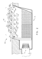
- FIG. 2 is a cross-sectional view of an example louver system 100 in an open position, according to at least some aspects of the present disclosure.
- FIG. 3 is a cross-sectional view of an example louver system 100 in a shut position, according to at least some aspects of the present disclosure.
- Louver system 100 may be disposed proximate a bleed system discharge opening 48, which may be arranged to vent bleed air from a bleed conduit 44.
- Louver system 100 may include a plurality of louvers 102, 104, 106, 108, 110, 112, which may pivotably disposed, such as by pivot pins 114, 116, 118, 120, 122, 124, respectively.
- Louvers 102, 104, 106, 108, 110, 112 may comprise respective trailing edges 150, 152, 154, 156, 158, 160.
- trailing edges 150, 152, 154, 156, 158, 160 may be located generally opposite pivot pins 114, 116, 118, 120, 122, 124, respectively.
- Pivot pins 114, 116, 118, 120, 122, 124 may be generally upstream and trailing edges 150, 152, 154, 156, 158, 160 may be generally downstream with respect to bleed air 2 and/or exit flow stream 5.
- Louvers 102, 104, 106, 108, 110, 112 may be pivotable between an open position (e.g., FIG. 2 ) and a shut position (e.g., FIG. 3 ).
- individual louvers 102, 104, 106, 108, 110, 112 may at least partially control a direction of exit flow stream 5 of bleed air 2 exiting discharge opening 48.
- louvers 102, 104, 106, 108, 110, 112 may direct exit flow stream 5 generally upward and to the right in FIG. 2 .
- An example louver system 100 installed in a turbofan aircraft engine may be configured to use louvers 102, 104, 106, 108, 110, 112 to direct exit flow 5 generally away from bypass duct walls 148, 149 ( FIG. 1 ).
- individual louvers 102, 104, 106, 108, 110, 112 may at least partially obstruct discharge opening 48.
- the plurality of louvers 102, 104, 106, 108, 110, 112 may substantially obstruct discharge opening 48.
- substantially obstructing discharge opening 48 when shut may enable louvers 102, 104, 106, 108, 110, 112 to prevent acoustic effects (e.g., whistling) and/or undesirable flow effects that may be caused by a substantially open discharge opening 48 with substantially no exit flow stream 5.
- louver system 48 may include a connecting rod 126 operatively coupled to two or more individual louvers 102, 104, 106, 108, 110, 112. Some example embodiments may include more than one connecting rod (see, e.g., FIG. 5 ).
- connecting rod 126 may be pivotably connected to louvers 102, 104, 106, 108, 110, 112 by pivot pins 128, 130, 132, 134, 136, 138.
- Connecting rod 126 may provide substantially coordinated pivoting of louvers 102, 104, 106, 108, 110, 112.
- louvers 102, 104, 106, 108, 110, 112 may pivot between open and shut positions in a substantially coordinated manner.
- louver system 100 may include an open position stopper 140, which may be arranged to limit pivoting of one or more of louvers 102, 104, 106, 108, 110, 112 in an opening direction 142 (e.g., FIG. 3 ).
- open position stopper 140 may directly limit pivoting of louver 102 in opening direction 142 by impeding rotation of louver 102 beyond a predetermined amount.
- Louvers 104, 106, 108, 110, 112 may also be limited in pivoting in opening direction 142 by louver 102 contacting open position stopper 140 because louvers 102, 104, 106, 108, 110, 112 may be linked together by connecting rod 126.
- louver system 100 may include a shut position stopper 144, which may be arranged to limit pivoting of one or more of louvers 102, 104, 106, 108, 110, 112 in a shutting direction 146 (e.g., FIG. 3 ).
- shut position stopper 144 may directly limit pivoting of louver 112 in shutting direction 146 by impeding rotation of louver 112 beyond a predetermined amount.
- Louvers 102, 104, 106, 108, 110 may also be limited in pivoting in shutting direction 146 by louver 112 contacting shut position stopper 144 because louvers 102, 104, 106, 108, 110, 112 may be linked together by connecting rod 126 and/or because louvers 102, 104, 106, 108, 110 may lie against louvers 104, 106, 108, 110, 112, respectively, in the shut position.
- Some example embodiments according to at least some aspects of the present disclosure may include more than one open position stopper 140 and/or more than one shut position stopper 144 (e.g., FIG. 3 ).
- An example embodiment may include open position stoppers 140 and/or shut position stoppers 144 associated with individual louvers 102, 104, 106, 108, 110, 112 and/or with groups of louvers 102, 104, 106, 108, 110, 112.
- louvers 102, 104, 106, 108, 110, 112 may pivot from the shut position to the open position upon receiving bleed air 2 flow from compressor 14. For example, a pressure differential across shut louvers 102, 104, 106, 108, 110, 112 may cause louvers 102, 104, 106, 108, 110, 112 to open. Upon substantially stopping the flow of bleed air 2 from compressor 14, louvers 102, 104, 106, 108, 110, 112 may pivot from the open position to the shut position. Louvers 102, 104, 106, 108, 110, 112 may remain in the shut position during conditions when there is substantially no bleed air 2 flow.
- FIG. 4 is a plan view of an example louver system 100, according to at least some aspects of the present disclosure.
- trailing edges 150, 152, 154, 156, 158, 160 may be generally straight and/or may include rounded peripheral corners.
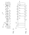
- FIG. 5 is a cross-sectional view of an example louver system 200 including a first connecting rod 226 and a second connecting rod 227, according to at least some aspects of the present disclosure.
- Louver system 200 may be mounted in bleed system discharge opening 48.
- Louver system 200 may include a plurality of louvers 202, 204, 206, 208, 210, 212, which may pivotably disposed, such as by pivot pins 214, 216, 218, 220, 222, 224, respectively.
- Louvers 202, 204, 206, 208, 210, 212 may comprise respective trailing edges 250, 252, 254, 256, 258, 260 (e.g., FIG. 5 ).
- trailing edges 250, 252, 254, 256, 258, 260 may be located generally opposite pivot pins 214, 216, 218, 220, 222, 224, respectively.
- Pivot pins 214, 216, 218, 220, 222, 224 may be generally upstream and trailing edges 250, 252, 254, 256, 258, 260 may be generally downstream with respect to exit flow stream 5.
- louvers 202, 204, 206, 208, 210, 212 of louver system 200 may be pivotable between an open position (e.g., louvers 202, 204, 206) and a shut position (e.g., louvers 208, 210, 212) (e.g., FIG. 5 ).
- an open position e.g., louvers 202, 204, 206
- a shut position e.g., louvers 208, 210, 212
- individual louvers 202, 204, 206, 208, 210, 212 may at least partially control a direction of exit flow stream 5 of bleed air 2 exiting discharge opening 48.
- one or more louvers 202, 204, 206, 208, 210, 212 may direct exit flow stream 5 generally upward and to the right in FIG. 5 .
- An example louver system 200 installed in a turbofan aircraft engine may be configured to use one or more louvers 202, 204, 206, 208, 210, 212
- individual louvers 202, 204, 206, 208, 210, 212 may at least partially obstruct discharge opening 48.
- the plurality of louvers 202, 204, 206, 208, 210, 212 may substantially obstruct discharge opening 48.
- first connecting rod 226 may be operatively coupled to two or more individual louvers 202, 204, 206 comprising a first group 262 of louvers and/or second connecting rod 227 may be operatively coupled to two or more individual louvers 208, 210, 212 comprising a second group 264 of louvers (e.g., FIG. 5 ).
- First connecting rod 226 may be pivotably connected to louvers 202, 204, 206 by pivot pins 228, 230, 232.
- First connecting rod 226 may provide substantially coordinated pivoting of first group 262 of louvers.
- louvers 202, 204, 206 may pivot between open and shut positions in a substantially coordinated manner.
- Second connecting rod 227 may be pivotably connected to louvers 208, 210, 212 by pivot pins 234, 236, 238. Second connecting rod 227 may provide substantially coordinated pivoting of first group 264 of louvers. For example, louvers 208, 210, 212 may pivot between open and shut positions in a substantially coordinated manner.
- louver system 200 may include an open position stopper 240, which may be arranged to limit pivoting of one or more of louvers 202, 204, 206, 208, 210, 212 in an opening direction 242.
- open position stopper 240 may directly limit pivoting of louver 202 in opening direction 242 by impeding rotation of louver 202 beyond a predetermined amount.
- Louvers 204, 206 may also be limited in pivoting in opening direction 242 by louver 202 contacting open position stopper 240 because louvers 202, 204, 206 may be linked together by first connecting rod 226.
- louver system 200 may include a shut position stopper 244, which may be arranged to limit pivoting of one or more of louvers 202, 204, 206, 208, 210, 212 in a shutting direction 246.
- shut position stopper 244 may directly limit pivoting of louver 212 in shutting direction 246 by impeding rotation of louver 212 beyond a predetermined amount.
- Louvers 202, 204, 206, 208, 210 may also be limited in pivoting in shutting direction 246 by louver 212 contacting shut position stopper 244 because louvers 202, 204, 206, 208, 210, 212 may be linked together by first connecting rod 226 and/or second connecting rod 227 and/or because louvers 202, 204, 206, 208, 210 may lie against louvers 204, 206, 208, 210, 212, respectively, in the shut position.
- first connecting rod 226 and second connecting rod 227 may be independently operable such that first group 262 of louvers and second group 264 of louvers may be at least partially independently pivotable (e.g., FIG. 5 ).
- louver system 200 may be configured such that first group 262 of louvers may be open at low and high bleed air 2 flow rates and/or second group 264 of louvers may be open at relatively high bleed air 2 flow rates and may be shut at relatively low flow rates.
- bleed air 2 flow may initially cause first group 262 of louvers to open, thereby discharging bleed air 2 as exit flow stream 5.
- Second group 264 of louvers may be maintained in the shut position.
- second group 264 of louvers may pivot to the open position. If the flow rate of bleed air 2 decreases, second group 264 of louvers may pivot to the shut position.
- first group 262 of louvers may pivot from the open position to the shut position.
- FIG. 6 is a plan view of an example louver system 300 including louvers 302, 304, 306, 308, 310, 312 with scalloped trailing edges 350, 352, 354 and/or chevron-shaped trailing edges 356, 358, 360, respectively, according to at least some aspects of the present disclosure.
- An example scalloped trailing edge 350 may include a plurality of alternating, generally curved projections 370, 372, 374 and/or recesses 376, 378.
- Some example embodiments may include a plurality of louvers having substantially the same shape of trailing edge, and some example embodiments may include a plurality of louvers having a plurality of different trailing edge shapes.
- FIG. 7 is a perspective view of an example louver 400 including a grooved trailing edge 404, according to at least some aspects of the present disclosure.
- Louver 400 may be pivotably mounted in a louver system generally as described in connection with other embodiments herein.
- louver 400 may receive a pivot pin through hole 402.
- Trailing edge 404 may be grooved, including a plurality of recesses 406, 408, 410, 412 interposed between a plurality of projections 414, 416, 418, 420, 422.
- recesses 406, 408, 410, 412 may be located on an area of trailing edge 404 that is generally opposite bypass flow stream 4.
- trailing edges with mixing features may improve mixing of exit flow stream 5 with bypass flow stream 4, for example.
- the sizes, proportions, and/or locations of projections 370, 372, 374, recesses 376, 378, projections 414, 416, 418, 420, 422, and/or recesses 406, 408, 410, 412 may be adjusted to achieve desired flow mixing characteristics.
- Some example embodiments may include one or more dampers operatively connected to one or more louvers. Such dampers may prevent and or limit flutter of the louvers.
- An example damper 161 may comprise a torsion spring operatively coupled between louver 102 and pivot pin 114, which may be staitionary. Damper 161 may initially resist opening movement of louver 102 until the differential pressure across louver 102 is sufficient to overcome the spring force.
- Alternative example damping systems may include one or more dampers operatively coupled to connecting rod 126 and/or one or more dampers operatively coupled between a rotating pivot pin 114 and a stationary part, such as open position stopper 140.
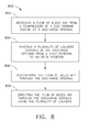
- FIG. 8 is flow chart of an example method 800 of operating a bleed system associated with a gas turbine engine, according to at least some aspects of the present disclosure.
- Method 800 may include an operation 802, which may include receiving a flow of bleed air from a compressor of a gas turbine engine at a discharge opening.
- Operation 802 may be followed by an operation 804, which may include pivoting a plurality of louvers disposed in the discharge opening from a shut position to an open position.
- Operation 804 may be followed by operation 806, which may include, discharging the flow of bleed air through the discharge opening.
- Operation 806 may be followed by operation 808, which may include directing the flow of bleed air through the discharge opening using the plurality of louvers.
Landscapes
- Engineering & Computer Science (AREA)
- Chemical & Material Sciences (AREA)
- Combustion & Propulsion (AREA)
- Mechanical Engineering (AREA)
- General Engineering & Computer Science (AREA)
- Physics & Mathematics (AREA)
- Fluid Mechanics (AREA)
- Structures Of Non-Positive Displacement Pumps (AREA)
- Control Of Turbines (AREA)
- Soundproofing, Sound Blocking, And Sound Damping (AREA)
- Air-Flow Control Members (AREA)
Abstract
Description
- The subject matter disclosed herein relates generally to bleed air systems for gas turbine engines, and, more specifically, to bleed air systems capable of providing pressure drops, acoustic improvements, and desirable flow properties.
- In a gas turbine engine, air is pressurized in a compression module. The air channeled through the compression module is mixed with fuel in a combustor and ignited, generating hot combustion gases, which flow through turbine stages that extract energy therefrom for powering the fan and compressor rotors and generate engine thrust to propel an aircraft in flight or to power a load, such as an electrical generator.
- In some gas turbine engines, a portion of the high-pressure air, such as, for example, bleed air from a compressor, may be extracted or bled from the compressor for various needs. These needs include, for example, compressor flow bleeding which may be used to improve operability as well as to provide turbine cooling, bearing sump pressurization, purge air, or aircraft environment control. The air may be bled off from the compressor using bleed slots located over specific portions or stages of the compressor.
- In at least some gas turbine engines, during engine operation occurring in some operating conditions, the compressor may pump more air than is required for needs including the combustion process. In order to manage operability of the engine and combustion performance, a portion of the excess bleed air from the compressor may be routed through bleed conduits and exhausted into the bypass flow stream, engine exhaust, or to ambient. The pressure and temperature of the air stream bled from the compressor may be very high. For example, bleed air pressure may be greater than about 1375 kPa and the bleed air temperature may be greater than about 538 degrees C. A transient bleed valve system (TBV) system and/or a variable bleed valve (VBV) system is sometimes used for bleeding and exhausting the air removed from the compressor. For example, the exhaust area of some conventional bleed systems may be oversized to lower the flow velocity at the exhaust location to assure that the acoustic requirements are met for the application. The exhaust area, as well as the expansions between the source pressure and exhaust, may contribute to the large size and/or weight of these systems.
- In addition, some exhaust designs on aircraft may require extensive thermal shielding on other components near the exhaust location,. Due to the nature of the high temperature and high pressure air, once it is discharged into the flow path, it may overwhelm the flowpath stream, causing the bleed air to impinge on the surrounding structure around the engine. In some aircraft, the surrounding structure may be made of lightweight composite material or of other metallic material with lesser temperature capability.
- In some applications (e.g., aircraft), it may be necessary to direct bleed air flow into the bypass stream to avoid thermal damage to bypass duct components.
- At least one solution for the above-mentioned problem(s) is provided by the present disclosure to include example embodiments, provided for illustrative teaching and not meant to be limiting.
- An example louver system for a gas turbine engine bleed system according to at least some aspects of the present disclosure may include a bleed system discharge opening arranged to vent bleed air from a bleed flow conduit and/or a plurality of pivotable louvers disposed proximate the discharge opening, the pivotable louvers being pivotable between a shut position and an open position. In the shut position, individual louvers may at least partially obstruct the discharge opening. In the open position, individual louvers may at least partially control a direction of flow of the bleed air exiting the discharge opening.
- An example gas turbine engine according to at least some aspects of the present disclosure may include a compressor; a combustor arranged to combust fuel in compressed air received from the compressor; a turbine configured to receive hot, pressurized gas from the combustor and to drive the compressor; a bleed conduit arranged to receive bleed air from the compressor; and/or a louver system operatively coupled to the bleed conduit. The louver system may include a plurality of louvers disposed in a discharge opening, the plurality of louvers being pivotable between a shut position and an open position.
- An example method of operating a bleed system associated with a gas turbine engine according to at least some aspects of the present disclosure may include receiving a flow of bleed air from a compressor of a gas turbine engine at a discharge opening; pivoting a plurality of louvers disposed in the discharge opening from a shut position to an open position; discharging the flow of bleed air through the discharge opening; and directing the flow of bleed air through the discharge opening using the plurality of louvers.
- The subject matter for which patent claim coverage is sought is particularly pointed out and claimed herein. The subject matter and embodiments thereof, however, may be best understood by reference to the following description taken in conjunction with the accompanying drawing figures in which:
-
FIG. 1 is a schematic cross-sectional view of a gas turbine engine including an example louver system; -
FIG. 2 is a cross-sectional view of an example louver system in an open position; -
FIG. 3 is a cross-sectional view of an example louver system in a shut position; -
FIG. 4 is a plan view of an example louver system; -
FIG. 5 is a cross-sectional view of an example louver system including a first connecting rod and a second connecting rod; -
FIG. 6 is a plan view of an example louver system including louvers with scalloped or chevron trailing edges; -
FIG. 7 is a perspective view of an example louver including a grooved trailing edge; and -
FIG. 8 is flow chart of an example method of operating a bleed system associated with a gas turbine engine, all in accordance with at least some aspects of the present disclosure. - In the following detailed description, reference is made to the accompanying drawings, which form a part hereof. In the drawings, similar symbols typically identify similar components, unless context dictates otherwise. The illustrative embodiments described in the detailed description, drawings, and claims are not meant to be limiting. Other embodiments may be utilized, and other changes may be made, without departing from the scope of the subject matter presented here. It will be readily understood that the aspects of the present disclosure, as generally described herein, and illustrated in the figures, can be arranged, substituted, combined, and designed in a wide variety of different configurations, all of which are explicitly contemplated and make part of this disclosure.
- The present disclosure includes, inter alia, gas turbine engines, bleed air systems, and methods of operating bleed air systems.
-
FIG. 1 is a schematic cross-sectional view of a gas turbine engine (GTE) 10 including anexample louver system 100, according to at least some aspects of the present disclosure. GTE 10 may include ableed system 40, which may incorporatelouver system 100. GTE 10 may include a coregas turbine engine 12 that includes a high-pressure compressor 14, acombustor 16, and/or a high-pressure turbine 18. GTE 10 may also include a low-pressure compressor 19, a low-pressure turbine 20, and/or afan assembly 22. - In operation, air may flow through
fan assembly 22. A portion of the air discharged fromfan assembly 22 may be channeled to high-pressure compressor 14, where it may be further compressed and channeled tocombustor 16. Products of combustion fromcombustor 16 may be utilized to drive high-pressure turbine 18 and/or low-pressure turbine 20. Another portion of the air discharged fromfan assembly 22 may bypass coregas turbine engine 10 and/or may be referred to as a bypass flow stream 4. - At some operating conditions, a portion of the compressed air produced by high-
pressure compressor 14 may be routed throughbleed system 40, thereby becomingbleed air 2. Bleedair 2 from high-pressure compressor 14 may enter a bleedflow conduit 44. Bleedair 2 may pass through bleedflow conduit 44, amuffling device 46, and/orlouver system 100, which may direct bleedair 2 into a flow path, such as the bypass flow stream 4. Bypass flow stream 4 may flow through a duct at partially defined bybypass duct walls air 2 through bleedflow conduit 44 may be controlled by a transient bleedvalve 45. - In some example embodiments, transient bleed
valve 45 may fluidicly interposecompressor 14 and bleedconduit 44.Muffling device 46 may fluidicly interpose bleedconduit 44 anddischarge opening 48. -
Louver system 100, described in more detail below, may be in flow communication with bleedflow conduit 44 such that bleedair 2 is discharged asexit flow stream 5 into bypass flow stream 4. Louversystem 100 may directexit flow stream 5 and/or may facilitate mixing ofexit flow stream 5 and bypass flow stream 4. Some example embodiments may include one or more structures configured to assist in controllingexit flow stream 5, such as an aero chimney, as described inU.S. Patent Application Publication No. 2011/0265490 , which is incorporated herein by reference. -
FIG. 2 is a cross-sectional view of anexample louver system 100 in an open position, according to at least some aspects of the present disclosure.FIG. 3 is a cross-sectional view of anexample louver system 100 in a shut position, according to at least some aspects of the present disclosure.Louver system 100 may be disposed proximate a bleedsystem discharge opening 48, which may be arranged to vent bleed air from a bleedconduit 44.Louver system 100 may include a plurality oflouvers pivot pins - Louvers 102, 104, 106, 108, 110, 112 may comprise respective
trailing edges trailing edges pivot pins Pivot pins trailing edges air 2 and/orexit flow stream 5. - Louvers 102, 104, 106, 108, 110, 112 may be pivotable between an open position (e.g.,
FIG. 2 ) and a shut position (e.g.,FIG. 3 ). In an example open position,individual louvers exit flow stream 5 ofbleed air 2 exitingdischarge opening 48. For example, when open,louvers exit flow stream 5 generally upward and to the right inFIG. 2 . Anexample louver system 100 installed in a turbofan aircraft engine may be configured to uselouvers direct exit flow 5 generally away frombypass duct walls 148, 149 (FIG. 1 ). - In an example shut position,
individual louvers discharge opening 48. In the shut position, the plurality oflouvers discharge opening 48. In some example embodiments, such as in aircraft turbofan engines, substantially obstructingdischarge opening 48 when shut may enablelouvers exit flow stream 5. - In some example embodiments,
louver system 48 may include a connectingrod 126 operatively coupled to two or moreindividual louvers FIG. 5 ). Returning toFIGS. 2 and3 , connectingrod 126 may be pivotably connected tolouvers pivot pins Connecting rod 126 may provide substantially coordinated pivoting oflouvers louvers - In some example embodiments,
louver system 100 may include anopen position stopper 140, which may be arranged to limit pivoting of one or more oflouvers FIG. 3 ). For example,open position stopper 140 may directly limit pivoting oflouver 102 in openingdirection 142 by impeding rotation oflouver 102 beyond a predetermined amount.Louvers direction 142 bylouver 102 contactingopen position stopper 140 becauselouvers rod 126. - In some example embodiments,
louver system 100 may include ashut position stopper 144, which may be arranged to limit pivoting of one or more oflouvers FIG. 3 ). For example, shutposition stopper 144 may directly limit pivoting oflouver 112 in shuttingdirection 146 by impeding rotation oflouver 112 beyond a predetermined amount.Louvers direction 146 bylouver 112 contacting shutposition stopper 144 becauselouvers rod 126 and/or becauselouvers louvers - Some example embodiments according to at least some aspects of the present disclosure may include more than one
open position stopper 140 and/or more than one shut position stopper 144 (e.g.,FIG. 3 ). An example embodiment may includeopen position stoppers 140 and/or shutposition stoppers 144 associated withindividual louvers louvers - In some example embodiments,
louvers bleed air 2 flow fromcompressor 14. For example, a pressure differential across shutlouvers louvers bleed air 2 fromcompressor 14,louvers Louvers bleed air 2 flow. -
FIG. 4 is a plan view of anexample louver system 100, according to at least some aspects of the present disclosure. In some example embodiments, trailingedges -
FIG. 5 is a cross-sectional view of anexample louver system 200 including a first connectingrod 226 and a second connectingrod 227, according to at least some aspects of the present disclosure.Louver system 200 may be mounted in bleedsystem discharge opening 48.Louver system 200 may include a plurality oflouvers pivot pins -
Louvers respective trailing edges FIG. 5 ). In some example embodiments, trailingedges edges exit flow stream 5. - Generally similar to
louver system 100,louvers louver system 200 may be pivotable between an open position (e.g.,louvers louvers FIG. 5 ). In an example open position,individual louvers exit flow stream 5 ofbleed air 2 exitingdischarge opening 48. For example, when open, one ormore louvers exit flow stream 5 generally upward and to the right inFIG. 5 . Anexample louver system 200 installed in a turbofan aircraft engine may be configured to use one ormore louvers direct exit flow 5 generally away frombypass duct walls - In an example shut position,
individual louvers discharge opening 48. In the shut position, the plurality oflouvers discharge opening 48. - In some example embodiments, first connecting
rod 226 may be operatively coupled to two or moreindividual louvers rod 227 may be operatively coupled to two or moreindividual louvers second group 264 of louvers (e.g.,FIG. 5 ). First connectingrod 226 may be pivotably connected tolouvers pivot pins rod 226 may provide substantially coordinated pivoting of first group 262 of louvers. For example,louvers rod 227 may be pivotably connected tolouvers pivot pins rod 227 may provide substantially coordinated pivoting offirst group 264 of louvers. For example,louvers - In some example embodiments,
louver system 200 may include anopen position stopper 240, which may be arranged to limit pivoting of one or more oflouvers opening direction 242. For example,open position stopper 240 may directly limit pivoting oflouver 202 in openingdirection 242 by impeding rotation oflouver 202 beyond a predetermined amount.Louvers direction 242 bylouver 202 contactingopen position stopper 240 becauselouvers rod 226. - In some example embodiments,
louver system 200 may include ashut position stopper 244, which may be arranged to limit pivoting of one or more oflouvers direction 246. For example, shutposition stopper 244 may directly limit pivoting oflouver 212 in shuttingdirection 246 by impeding rotation oflouver 212 beyond a predetermined amount.Louvers direction 246 bylouver 212 contacting shutposition stopper 244 becauselouvers rod 226 and/or second connectingrod 227 and/or becauselouvers louvers - In some example embodiments, first connecting
rod 226 and second connectingrod 227 may be independently operable such that first group 262 of louvers andsecond group 264 of louvers may be at least partially independently pivotable (e.g.,FIG. 5 ). For example,louver system 200 may be configured such that first group 262 of louvers may be open at low andhigh bleed air 2 flow rates and/orsecond group 264 of louvers may be open at relativelyhigh bleed air 2 flow rates and may be shut at relatively low flow rates. - In an example embodiment, bleed
air 2 flow may initially cause first group 262 of louvers to open, thereby dischargingbleed air 2 asexit flow stream 5.Second group 264 of louvers may be maintained in the shut position. In response to an increase inbleed air 2 flow,second group 264 of louvers may pivot to the open position. If the flow rate ofbleed air 2 decreases,second group 264 of louvers may pivot to the shut position. Upon substantially stopping the flow ofbleed air 2 fromcompressor 14, first group 262 of louvers may pivot from the open position to the shut position. - Some example embodiments according to at least some aspects of the present disclosure may include louvers comprising trailing edges with mixing features. For example,
FIG. 6 is a plan view of anexample louver system 300 includinglouvers edges trailing edges edge 350 may include a plurality of alternating, generally curvedprojections - Another example mixing feature may comprise a grooved edge.
FIG. 7 is a perspective view of anexample louver 400 including agrooved trailing edge 404, according to at least some aspects of the present disclosure.Louver 400 may be pivotably mounted in a louver system generally as described in connection with other embodiments herein. For example,louver 400 may receive a pivot pin throughhole 402. Trailingedge 404 may be grooved, including a plurality ofrecesses projections edge 404 that is generally opposite bypass flow stream 4. - In some example embodiments, trailing edges with mixing features (e.g., scalloped edges and/or grooved edges) may improve mixing of
exit flow stream 5 with bypass flow stream 4, for example. The sizes, proportions, and/or locations ofprojections projections - Some example embodiments may include one or more dampers operatively connected to one or more louvers. Such dampers may prevent and or limit flutter of the louvers. An
example damper 161 may comprise a torsion spring operatively coupled betweenlouver 102 andpivot pin 114, which may be staitionary.Damper 161 may initially resist opening movement oflouver 102 until the differential pressure acrosslouver 102 is sufficient to overcome the spring force. Alternative example damping systems may include one or more dampers operatively coupled to connectingrod 126 and/or one or more dampers operatively coupled between arotating pivot pin 114 and a stationary part, such asopen position stopper 140. -
FIG. 8 is flow chart of anexample method 800 of operating a bleed system associated with a gas turbine engine, according to at least some aspects of the present disclosure.Method 800 may include anoperation 802, which may include receiving a flow of bleed air from a compressor of a gas turbine engine at a discharge opening.Operation 802 may be followed by anoperation 804, which may include pivoting a plurality of louvers disposed in the discharge opening from a shut position to an open position.Operation 804 may be followed byoperation 806, which may include, discharging the flow of bleed air through the discharge opening.Operation 806 may be followed byoperation 808, which may include directing the flow of bleed air through the discharge opening using the plurality of louvers. - This written description uses examples to disclose the invention, including the best mode, and also to enable any person skilled in the art to practice the invention, including making and using any devices or systems and performing any incorporated methods. The patentable scope of the invention is defined by the claims, and may include other examples that occur to those skilled in the art. Such other examples are intended to be within the scope of the claims if they have structural elements that do not differ from the literal language of the claims, or if they include equivalent structural elements with insubstantial differences from the literal languages of the claims.
- Various aspects and embodiments of the present invention are defmed by the following numbered clauses:
- 1. A louver system for a gas turbine engine bleed system, the louver system comprising:
- a bleed system discharge opening arranged to vent bleed air from a bleed flow conduit; and
- a plurality of pivotable louvers disposed proximate the discharge opening, the pivotable louvers being pivotable between a shut position and an open position;
- wherein, in the shut position, individual louvers at least partially obstruct the discharge opening; and
- wherein, in the open position, individual louvers at least partially control a direction of flow of the bleed air exiting the discharge opening.
- 2. The louver system of clause 1, further comprising a first connecting rod operatively coupled to a first louver of the plurality of louvers and to a second louver of the plurality of louvers, the first connecting rod providing substantially coordinated pivoting of the first louver and the second louver.
- 3. The louver system of any preceding clause, further comprising a second connecting rod operatively coupled to a third louver of the plurality of louvers and to a fourth louver of the plurality of louvers, the second connecting rod providing substantially coordinated pivoting of the third louver and the fourth louver.
- 4. The louver system of any preceding clause, wherein the first connecting rod and the second connecting rod are independently operable.
- 5. The louver system of any preceding clause, wherein the plurality of pivotable louvers comprises at least two groups of louvers, each group of louvers being associated with a connecting rod providing substantially coordinated pivoting of the respective group of louvers.
- 6. The louver system of any preceding clause, further comprising an open position stopper arranged to limit pivoting of at least one louver of the plurality of louvers in an opening direction.
- 7. The louver system of any preceding clause, further comprising a shut position stopper arranged to limit pivoting of at least one louver of the plurality of louvers in a shutting direction.
- 8. The louver system of any preceding clause, wherein an individual louver comprises a trailing edge; wherein the trailing edge comprises a mixing feature; and wherein the mixing feature comprises at least one of a grooved edge, a scalloped edge, and a chevron-shaped edge.
- 9. A gas turbine engine, comprising:
- a compressor;
- a combustor arranged to combust fuel in compressed air received from the compressor;
- a turbine configured to receive hot, pressurized gas from the combustor and to drive the compressor;
- a bleed conduit arranged to receive bleed air from the compressor; and
- a louver system operatively coupled to the bleed conduit, the louver system comprising
- a plurality of louvers disposed in a discharge opening, the plurality of louvers being pivotable between a shut position and an open position.
- 10. The gas turbine engine of any preceding clause, wherein, in the shut position, the plurality of louvers substantially obstructs the discharge opening.
- 11. The gas turbine engine of any preceding clause, wherein, in the open position, the plurality of louvers are arranged to direct a flow of bleed air exiting the discharge opening.
- 12. The gas turbine engine of any preceding clause, further comprising
a transient bleed valve fluidicly interposing the compressor and the bleed conduit; and
a muffling device fluidicly interposing the bleed conduit and the discharge opening. - 13. The gas turbine engine of any preceding clause, wherein the discharge opening is arranged to vent the bleed air into a bypass flow stream.
- 14. The gas turbine engine of any preceding clause3, wherein, in the open position, the plurality of louvers is arranged to prevent bleed air impingement on a bypass duct wall.
- 15. A method of operating a bleed system associated with a gas turbine engine, the method comprising:
- receiving a flow of bleed air from a compressor of a gas turbine engine at a discharge opening;
- pivoting a plurality of louvers disposed in the discharge opening from a shut position to an open position;
- discharging the flow of bleed air through the discharge opening; and
- directing the flow of bleed air through the discharge opening using the plurality of louvers.
- 16. The method of any preceding clause, further comprising
substantially stopping the flow of bleed air from the compressor; and
pivoting the plurality of louvers from the open position to the shut position, the louvers substantially obstructing the discharge opening in the shut position. - 17. The method of any preceding clause, wherein pivoting a plurality of louvers disposed in the discharge opening from the shut position to the open position comprises
pivoting a first group of pivotable louvers from the shut position to the open position, and
maintaining a second group of pivotable louvers in the shut position. - 18. The method of any preceding clause, further comprising pivoting the second group of louvers from the shut position to the open position in response to an increase in a flow rate of bleed air from the compressor.
- 19. The method of any preceding clause, wherein receiving the flow of bleed air from the compressor of the gas turbine engine at the discharge opening comprises flowing the flow of bleed air through a muffling device fluidicly coupled upstream of the discharge opening.
Claims (15)
- A louver system (100) for a gas turbine engine bleed system (40), the louver system comprising:a bleed system discharge opening (48) arranged to vent bleed air (2) from a bleed flow conduit (44); anda plurality of pivotable louvers (102,104...112) disposed proximate the discharge opening (48), the pivotable louvers being pivotable between a shut position and an open position;wherein, in the shut position, individual louvers at least partially obstruct the discharge opening (48); andwherein, in the open position, individual louvers at least partially control a direction of flow (5) of the bleed air (2) exiting the discharge opening (48).
- The louver system (100) of claim 1, further comprising a first connecting rod (126) operatively coupled to a first louver (102) of the plurality of louvers and to a second louver (104) of the plurality of louvers, the first connecting rod providing substantially coordinated pivoting of the first louver and the second louver.
- The louver system (200) of claim 2, further comprising a second connecting rod (227) operatively coupled to a third louver (208) of the plurality of louvers and to a fourth louver (210) of the plurality of louvers, the second connecting rod (227) providing substantially coordinated pivoting of the third louver (208) and the fourth louver (210).
- The louver system (200) of claim 3, wherein the first connecting rod (226) and the second connecting rod (227) are independently operable.
- The louver system (200) of claim 1, wherein the plurality of pivotable louvers (202,204...212) comprises at least two groups (262,264) of louvers, each group of louvers being associated with a connecting rod (226,227) providing substantially coordinated pivoting of the respective group of louvers.
- The louver system (100) of any of the preceding claims, further comprising an open position stopper (140) arranged to limit pivoting of at least one louver of the plurality of louvers in an opening direction.
- The louver system (100) of any of the preceding claims, further comprising a shut position stopper (144) arranged to limit pivoting of at least one louver of the plurality of louvers in a shutting direction.
- The louver system of any of the preceding claims, wherein an individual louver comprises a trailing edge; wherein the trailing edge comprises a mixing feature; and wherein the mixing feature comprises at least one of a grooved edge (404), a scalloped edge (350,352,354), and a chevron-shaped edge (356,358,360).
- A gas turbine engine (10), comprising:a compressor (14);a combustor (16) arranged to combust fuel in compressed air received from the compressor;a turbine (18) configured to receive hot, pressurized gas from the combustor (16) and to drive the compressor (14);a bleed conduit (44) arranged to receive bleed air (2) from the compressor (14); anda louver system (100) operatively coupled to the bleed conduit (44), the louver system comprisinga plurality of louvers (102,104...112) disposed in a discharge opening (48), the plurality of louvers being pivotable between a shut position and an open position.
- The gas turbine engine (10) of claim 9, further comprising
a transient bleed valve (45) fluidicly interposing the compressor (14) and the bleed conduit (44); and
a muffling device (46) fluidicly interposing the bleed conduit (44) and the discharge opening (48). - The gas turbine engine (10) of either of claim 9 or 10, wherein the discharge opening (48) is arranged to vent the bleed air (2) into a bypass flow stream (4).
- The gas turbine engine (10) of claim 11, wherein, in the open position, the plurality of louvers (102,103...112) is arranged to prevent bleed air impingement on a bypass duct wall (148,149).
- A method (800) of operating a bleed system associated with a gas turbine engine, the method comprising:receiving (802) a flow of bleed air from a compressor of a gas turbine engine at a discharge opening;pivoting (804) a plurality of louvers disposed in the discharge opening from a shut position to an open position;discharging (806) the flow of bleed air through the discharge opening; anddirecting (808) the flow of bleed air through the discharge opening using the plurality of louvers.
- The method of claim 13, further comprising
substantially stopping the flow of bleed air (2) from the compressor (14); and
pivoting the plurality of louvers (102,104..112) from the open position to the shut position, the louvers substantially obstructing the discharge opening in the shut position. - The method of either of claim 13 or 14, wherein pivoting a plurality of louvers disposed in the discharge opening from the shut position to the open position comprises
pivoting a first group (262) of pivotable louvers from the shut position to the open position, and
maintaining a second group (264) of pivotable louvers in the shut position.
Applications Claiming Priority (1)
| Application Number | Priority Date | Filing Date | Title |
|---|---|---|---|
| US13/448,517 US9399951B2 (en) | 2012-04-17 | 2012-04-17 | Modular louver system |
Publications (2)
| Publication Number | Publication Date |
|---|---|
| EP2653699A2 true EP2653699A2 (en) | 2013-10-23 |
| EP2653699A3 EP2653699A3 (en) | 2017-05-17 |
Family
ID=48139736
Family Applications (1)
| Application Number | Title | Priority Date | Filing Date |
|---|---|---|---|
| EP13163434.7A Withdrawn EP2653699A3 (en) | 2012-04-17 | 2013-04-11 | Modular louver system |
Country Status (6)
| Country | Link |
|---|---|
| US (1) | US9399951B2 (en) |
| EP (1) | EP2653699A3 (en) |
| JP (1) | JP2013221520A (en) |
| CN (1) | CN103375304B (en) |
| BR (1) | BR102013008566A2 (en) |
| CA (1) | CA2811821A1 (en) |
Cited By (6)
| Publication number | Priority date | Publication date | Assignee | Title |
|---|---|---|---|---|
| FR3018096A1 (en) * | 2014-03-03 | 2015-09-04 | Snecma | DISCHARGE DUCT FOR A TURBOMACHINE |
| WO2016156739A1 (en) * | 2015-04-01 | 2016-10-06 | Snecma | Discharge flow duct of a turbine engine comprising a vbv grating with variable setting |
| FR3034462A1 (en) * | 2015-04-01 | 2016-10-07 | Snecma | TURBOMACHINE DISCHARGE VEIN CONDUIT COMPRISING A VARIABLE SECTION VBV GRID |
| EP3088703A1 (en) * | 2015-04-30 | 2016-11-02 | General Electric Company | Turbine engine thermal management |
| GB2550201A (en) * | 2016-05-13 | 2017-11-15 | Rolls Royce Plc | Gas turbine engine |
| FR3111948A1 (en) * | 2020-06-30 | 2021-12-31 | Safran Aircraft Engines | discharge valve for withdrawing fluid circulating in a turbomachine stream |
Families Citing this family (19)
| Publication number | Priority date | Publication date | Assignee | Title |
|---|---|---|---|---|
| EP2696040B1 (en) * | 2012-08-09 | 2017-03-15 | MTU Aero Engines AG | Flow guidance device for cooling the low pressure turbine casing of a gas turbine engine |
| US20140338360A1 (en) * | 2012-09-21 | 2014-11-20 | United Technologies Corporation | Bleed port ribs for turbomachine case |
| GB201322833D0 (en) | 2013-12-23 | 2014-02-12 | Rolls Royce Plc | |
| FR3036136B1 (en) * | 2015-05-15 | 2019-07-12 | Safran | INTERMEDIATE CASTER HUB FOR AIRCRAFT TURBOREACTOR COMPRISING A COMPOSITE DISCHARGE DUCT |
| FR3037617B1 (en) * | 2015-06-17 | 2019-06-28 | Safran Aircraft Engines | TURBOMACHINE DISCHARGE VEIN CONDUIT COMPRISING VARIABLE SECTION VBV GRID AND PASSIVE ACTUATION |
| US10077740B2 (en) * | 2015-10-16 | 2018-09-18 | The Boeing Company | Folding door thrust reversers for aircraft engines |
| US10794282B2 (en) * | 2016-01-25 | 2020-10-06 | Rolls-Royce North American Technologies Inc. | Inlet turbine for high-mach engines |
| US10934942B2 (en) | 2016-02-16 | 2021-03-02 | Rolls-Royce North American Technologies Inc. | Inlet turbine and transmission for high-mach engines |
| ITUA20161507A1 (en) * | 2016-03-09 | 2017-09-09 | Gen Electric | GAS TURBOMOTOR WITH AN AIR BREAKING. |
| CN105840314B (en) * | 2016-04-26 | 2017-09-19 | 中科合肥微小型燃气轮机研究院有限责任公司 | Gas turbine test bench exhaust system with heat storage |
| US10221773B2 (en) | 2016-10-07 | 2019-03-05 | General Electric Company | Bleed valve assembly for a gas turbine engine |
| US10233845B2 (en) | 2016-10-07 | 2019-03-19 | General Electric Company | Bleed valve assembly for a gas turbine engine |
| CN108267010B (en) * | 2018-03-28 | 2023-10-27 | 中冶长天国际工程有限责任公司 | A gas injection device and injection method that eliminates the influence of cross wind |
| GB201807267D0 (en) * | 2018-05-03 | 2018-06-20 | Rolls Royce Plc | Louvre offtake arrangement |
| GB201808852D0 (en) * | 2018-05-31 | 2018-07-18 | Rolls Royce Plc | Gas turbine engine |
| US11078842B2 (en) * | 2019-03-26 | 2021-08-03 | Raytheon Technologies Corporation | Exhaust distribution manifold |
| US10927761B2 (en) * | 2019-04-17 | 2021-02-23 | General Electric Company | Refreshing heat management fluid in a turbomachine |
| US11702995B2 (en) | 2020-07-15 | 2023-07-18 | Pratt & Whitney Canada Corp. | Devices and methods for guiding bleed air in a turbofan engine |
| FR3115837B1 (en) * | 2020-11-03 | 2025-09-19 | Safran Aircraft Engines | ASSEMBLY FOR A DOUBLE-FLOW AIRCRAFT TURBOMACHINE, THE ASSEMBLY BEING EQUIPPED WITH INCIDENCE-DRIVEN AIR DISCHARGE VINES |
Family Cites Families (101)
| Publication number | Priority date | Publication date | Assignee | Title |
|---|---|---|---|---|
| US700785A (en) | 1901-03-22 | 1902-05-27 | Albert L Kull | Muffler for explosive or other engines. |
| US1473349A (en) | 1921-04-01 | 1923-11-06 | Kach Robert | Gas mixer |
| US1539595A (en) | 1921-10-10 | 1925-05-26 | Powell Herbert Spencer | Muffler for explosive engines |
| US1697794A (en) | 1927-02-28 | 1929-01-01 | Gen Motors Corp | Exhaust-manifold muffler |
| US1794276A (en) | 1929-12-14 | 1931-02-24 | John J Bowes | Exhaust muffler |
| US2701557A (en) | 1950-11-24 | 1955-02-08 | Axiuer J Ramey | Atomizing and mixing device for internal-combustion engines |
| US2919761A (en) | 1957-05-13 | 1960-01-05 | Vernon N Holderman | Mufflers |
| US2929248A (en) | 1957-11-13 | 1960-03-22 | Bailey Meter Co | Flow meter |
| US3092206A (en) | 1958-12-29 | 1963-06-04 | Moreau Rene | Internal combustion engine silencers |
| US3016972A (en) | 1959-04-10 | 1962-01-16 | Rebert J Dugas | Muffler for an internal combustion engine |
| US3120877A (en) | 1960-10-27 | 1964-02-11 | Curtiss Wright Corp | Exhaust noise suppressor for reaction engines |
| US3159238A (en) | 1960-12-01 | 1964-12-01 | Curtiss Wright Corp | Diffuser screen with heat-insulating rungs for exhaust noise suppressor for reactionengines |
| US3105570A (en) | 1962-04-17 | 1963-10-01 | Bezemes Nicholas | Internal combustion engine exhaust muffler |
| US3191630A (en) | 1963-04-11 | 1965-06-29 | Cottrell Res Inc | Gas flow control system for sub-sonic divergent diffusers |
| US3338331A (en) | 1965-03-05 | 1967-08-29 | Walker Mfg Co | Exhaust system with plural silencing units |
| US3398881A (en) | 1967-01-10 | 1968-08-27 | United Aircraft Corp | Compressor bleed device |
| US3545492A (en) | 1968-05-16 | 1970-12-08 | Armco Steel Corp | Multiple plate throttling orifice |
| US3493169A (en) | 1968-06-03 | 1970-02-03 | United Aircraft Corp | Bleed for compressor |
| US3572391A (en) | 1969-07-10 | 1971-03-23 | Hirsch Abraham A | Flow uniformizing baffling for closed process vessels |
| US3632223A (en) | 1969-09-30 | 1972-01-04 | Gen Electric | Turbine engine having multistage compressor with interstage bleed air system |
| US3665965A (en) | 1970-05-26 | 1972-05-30 | Masonellan International Inc | Apparatus for reducing flowing fluid pressure with low noise generation |
| US3840051A (en) | 1971-03-11 | 1974-10-08 | Mitsubishi Heavy Ind Ltd | Straightener |
| US3692140A (en) | 1971-04-05 | 1972-09-19 | Cloyd D Smith | Exhaust noise suppressor for gas turbine |
| US4130173A (en) | 1971-10-01 | 1978-12-19 | Vought Corporation | Apparatus and method for reducing flow disturbances in a flowing stream of compressible fluid |
| US3777489A (en) | 1972-06-01 | 1973-12-11 | Gen Electric | Combustor casing and concentric air bleed structure |
| GB1454630A (en) | 1973-12-11 | 1976-11-03 | Electricite De France | Axial-flow fan |
| US3945759A (en) | 1974-10-29 | 1976-03-23 | General Electric Company | Bleed air manifold |
| US3964519A (en) | 1974-11-18 | 1976-06-22 | Air Monitor Corporation | Fluid velocity equalizing apparatus |
| DE2530800A1 (en) | 1975-07-10 | 1977-01-27 | Volkswagenwerk Ag | CONNECTING LINE WITHIN AN EXHAUST SYSTEM OF A MOTOR VEHICLE |
| GB1547168A (en) | 1975-09-25 | 1979-06-06 | British Gas Corp | Gas-flow noise reduction systems |
| US4022112A (en) | 1975-12-15 | 1977-05-10 | The Bendix Corporation | Flow through cap for attenuating any noise caused by air flow in a pneumatic servomotor |
| NL181292C (en) | 1976-06-08 | 1987-07-16 | Nederlandse Gasunie Nv | DEVICE FOR IMPROVING THE FLOW PROFILE IN A GAS PIPE. |
| US4128769A (en) | 1976-09-27 | 1978-12-05 | The Garrett Corporation | Eductor muffler |
| FR2370867A1 (en) | 1976-11-16 | 1978-06-09 | Pellerin Albert | DEVICE MAKING THE AIR-GASOLINE MIXTURE MORE HOMOGENEOUS IN EXPLOSION ENGINES |
| US4156344A (en) | 1976-12-27 | 1979-05-29 | The Boeing Company | Inlet guide vane bleed system |
| US4244440A (en) | 1978-12-01 | 1981-01-13 | General Electric Company | Apparatus for suppressing internally generated gas turbine engine low frequency noise |
| US4244441A (en) | 1979-07-31 | 1981-01-13 | The Garrett Corporation | Broad band acoustic attenuator |
| US4375841A (en) | 1981-06-18 | 1983-03-08 | Fluid Kinetics Corporation | Fluid flow apparatus for accommodating a pressure drop |
| JPS5897515A (en) * | 1981-12-04 | 1983-06-10 | Nissan Motor Co Ltd | Ventilator grill |
| US4463552A (en) | 1981-12-14 | 1984-08-07 | United Technologies Corporation | Combined surge bleed and dust removal system for a fan-jet engine |
| US4537277A (en) | 1982-12-03 | 1985-08-27 | The Secretary Of State For Defence In Her Britannic Majesty's Government Of The United Kingdom Of Great Britain And Northern Ireland | Silencer for high velocity gas flow |
| DE3464128D1 (en) | 1983-04-08 | 1987-07-16 | Avl Verbrennungskraft Messtech | Automotive vehicle |
| US4685533A (en) | 1985-12-27 | 1987-08-11 | General Dynamics, Pomona Division | Exhaust dissipator device |
| GB2196911B (en) * | 1986-10-30 | 1990-03-14 | Rolls Royce Plc | Thrust reverser |
| AU598944B2 (en) | 1987-07-22 | 1990-07-05 | Engenuity Pty Ltd | A gas blow-off attenuator |
| US4890691A (en) | 1988-11-16 | 1990-01-02 | Ching Ho Chen | Muffler |
| US4979587A (en) | 1989-08-01 | 1990-12-25 | The Boeing Company | Jet engine noise suppressor |
| JP2606466B2 (en) * | 1991-03-25 | 1997-05-07 | 三菱電機株式会社 | Air conditioner wind direction control device |
| US5205719A (en) | 1992-01-13 | 1993-04-27 | Copeland Corporation | Refrigerant compressor discharge muffler |
| US5327941A (en) | 1992-06-16 | 1994-07-12 | The United States Of America As Represented By The Secretary Of The Navy | Cascade orificial resistive device |
| US5429102A (en) | 1992-06-23 | 1995-07-04 | Anhydrous Devices, Inc. | Fuel saving device |
| US5261228A (en) | 1992-06-25 | 1993-11-16 | General Electric Company | Apparatus for bleeding air |
| US5758488A (en) | 1993-05-11 | 1998-06-02 | Roderick Thomson | Core flow expansion chamber device system for reduction of jet turbine engine noise |
| US5495872A (en) | 1994-01-31 | 1996-03-05 | Integrity Measurement Partners | Flow conditioner for more accurate measurement of fluid flow |
| US5428954A (en) | 1994-04-11 | 1995-07-04 | Cowan, Sr.; Howard H. | System for suppressing engine exhaust noise |
| US5557917A (en) | 1994-09-13 | 1996-09-24 | Scientific Monitoring, Inc. | Engine stall and distortion suppression system |
| CA2133793A1 (en) * | 1994-10-06 | 1996-04-07 | William E. Carscallen | Inter compressor duct variable geometry annular diffuser/bleed valve |
| US5580307A (en) * | 1995-02-22 | 1996-12-03 | Arosio F. Lli S.N.C. | Shutter for air or smoke conduits |
| US5706649A (en) * | 1995-04-03 | 1998-01-13 | Boeing North American, Inc. | Multi axis thrust vectoring for turbo fan engines |
| FR2776033B1 (en) | 1998-03-13 | 2000-08-18 | Gaz De France | FLOW CONDITIONER FOR GAS TRANSPORT PIPING |
| CA2275851A1 (en) | 1998-06-19 | 1999-12-19 | Kiyomori Asano | Two stroke, multiple cylinder engine for small vehicle |
| DE19959596A1 (en) | 1999-12-10 | 2001-06-13 | Rolls Royce Deutschland | Blow-off valve of a compressor, in particular for a twin-jet aircraft engine |
| US6558137B2 (en) | 2000-12-01 | 2003-05-06 | Tecumseh Products Company | Reciprocating piston compressor having improved noise attenuation |
| US6695094B2 (en) | 2001-02-02 | 2004-02-24 | The Boeing Company | Acoustic muffler for turbine engine |
| US6733240B2 (en) * | 2001-07-18 | 2004-05-11 | General Electric Company | Serrated fan blade |
| US6565313B2 (en) | 2001-10-04 | 2003-05-20 | United Technologies Corporation | Bleed deflector for a gas turbine engine |
| US20050067218A1 (en) | 2001-11-21 | 2005-03-31 | Dunlop Aerospace Limited | Noise attenuator arrangement |
| JP3962981B2 (en) * | 2001-12-07 | 2007-08-22 | 石川島播磨重工業株式会社 | Jet jet mixer |
| US6807986B2 (en) | 2002-03-22 | 2004-10-26 | Dresser, Inc. | Noise reduction device for fluid flow systems |
| US7089963B2 (en) | 2002-11-26 | 2006-08-15 | David Meheen | Flow laminarizing device |
| US8580076B2 (en) | 2003-05-22 | 2013-11-12 | Lam Research Corporation | Plasma apparatus, gas distribution assembly for a plasma apparatus and processes therewith |
| GB2405666A (en) * | 2003-09-05 | 2005-03-09 | Dunlop Aerospace Ltd | Noise attenuator, eg for turbofan engine air bleed system |
| DE10341319B4 (en) | 2003-09-08 | 2006-02-02 | Veritas Ag | silencer |
| US7147426B2 (en) | 2004-05-07 | 2006-12-12 | Pratt & Whitney Canada Corp. | Shockwave-induced boundary layer bleed |
| DE102004028744B3 (en) | 2004-06-14 | 2005-10-27 | Veritas Ag | silencer |
| US7267297B2 (en) | 2004-09-02 | 2007-09-11 | The Boeing Company | Integrated axially varying engine muffler, and associated methods and systems |
| US7364116B2 (en) | 2004-09-27 | 2008-04-29 | The Boeing Company | Automatic control systems for aircraft auxiliary power units, and associated methods |
| US7344107B2 (en) | 2004-10-26 | 2008-03-18 | The Boeing Company | Dual flow APU inlet and associated systems and methods |
| US7513119B2 (en) | 2005-02-03 | 2009-04-07 | The Boeing Company | Systems and methods for starting aircraft engines |
| US7367424B2 (en) | 2005-02-14 | 2008-05-06 | Honeywell International, Inc. | Eccentric exhaust muffler for use with auxiliary power units |
| FR2882112B1 (en) | 2005-02-16 | 2007-05-11 | Snecma Moteurs Sa | HEAD SAMPLING OF HIGH PRESSURE COMPRESSOR MOBILE WHEELS FROM TURBOREACTOR |
| US7146961B1 (en) | 2005-02-18 | 2006-12-12 | Jeff Westcott | Engine air inlet flow enhancement device for internal combustion engines |
| WO2006091138A1 (en) * | 2005-02-25 | 2006-08-31 | Volvo Aero Corporation | A bleed structure for a bleed passage in a gas turbine engine |
| US7431125B2 (en) | 2005-03-15 | 2008-10-07 | Honeywell International Inc. | Composite muffler for use with airborne auxiliary power unit |
| US7624581B2 (en) * | 2005-12-21 | 2009-12-01 | General Electric Company | Compact booster bleed turbofan |
| US7946104B2 (en) * | 2006-05-12 | 2011-05-24 | Rohr, Inc. | Bleed air relief system for engines |
| US7797945B2 (en) | 2006-09-06 | 2010-09-21 | Honeywell International Inc. | Bleed valve outlet flow deflector |
| US7765784B2 (en) | 2006-09-25 | 2010-08-03 | The Boeing Company | Thermally compliant APU exhaust duct arrangements and associated systems and methods |
| GB2443418B (en) | 2006-11-02 | 2011-05-04 | Rolls Royce Plc | An acoustic arrangement |
| US7762374B2 (en) | 2006-11-22 | 2010-07-27 | Honeywell International Inc. | Turbine engine diffusing exhaust muffler |
| GB0801301D0 (en) * | 2008-01-25 | 2008-03-05 | Rolls Royce Plc | Aeroengine bleed valve |
| GB0810883D0 (en) | 2008-06-16 | 2008-07-23 | Rolls Royce Plc | A bleed valve arrangement |
| GB0820597D0 (en) | 2008-11-11 | 2008-12-17 | Rolls Royce Plc | A noise reduction device |
| GB0820598D0 (en) | 2008-11-11 | 2008-12-17 | Rolls Royce Plc | A noise reduction device |
| US7798285B2 (en) | 2008-11-14 | 2010-09-21 | Rohr, Inc. | Acoustic barrel for aircraft engine nacelle including crack and delamination stoppers |
| GB2468669C (en) | 2009-03-17 | 2013-11-13 | Rolls Royce Plc | A flow discharge device |
| US20110265490A1 (en) | 2010-04-30 | 2011-11-03 | Kevin Samuel Klasing | Flow mixing vent system |
| US8016071B1 (en) | 2010-06-21 | 2011-09-13 | Trane International Inc. | Multi-stage low pressure drop muffler |
| US8266888B2 (en) * | 2010-06-24 | 2012-09-18 | Pratt & Whitney Canada Corp. | Cooler in nacelle with radial coolant |
| US8307943B2 (en) | 2010-07-29 | 2012-11-13 | General Electric Company | High pressure drop muffling system |
| US8511096B1 (en) | 2012-04-17 | 2013-08-20 | General Electric Company | High bleed flow muffling system |
-
2012
- 2012-04-17 US US13/448,517 patent/US9399951B2/en active Active
-
2013
- 2013-04-04 CA CA2811821A patent/CA2811821A1/en not_active Abandoned
- 2013-04-09 BR BR102013008566A patent/BR102013008566A2/en not_active IP Right Cessation
- 2013-04-11 EP EP13163434.7A patent/EP2653699A3/en not_active Withdrawn
- 2013-04-16 JP JP2013085744A patent/JP2013221520A/en active Pending
- 2013-04-17 CN CN201310133088.XA patent/CN103375304B/en active Active
Cited By (12)
| Publication number | Priority date | Publication date | Assignee | Title |
|---|---|---|---|---|
| FR3018096A1 (en) * | 2014-03-03 | 2015-09-04 | Snecma | DISCHARGE DUCT FOR A TURBOMACHINE |
| WO2016156739A1 (en) * | 2015-04-01 | 2016-10-06 | Snecma | Discharge flow duct of a turbine engine comprising a vbv grating with variable setting |
| FR3034461A1 (en) * | 2015-04-01 | 2016-10-07 | Snecma | TURBOMACHINE DISCHARGE VEIN CONDUIT COMPRISING A VARIABLE-SET VBV GRID |
| FR3034462A1 (en) * | 2015-04-01 | 2016-10-07 | Snecma | TURBOMACHINE DISCHARGE VEIN CONDUIT COMPRISING A VARIABLE SECTION VBV GRID |
| RU2715766C2 (en) * | 2015-04-01 | 2020-03-03 | Сафран Эркрафт Энджинз | Gas turbine engine bypass channel, containing channel closure grate with different mounting angles |
| US10794218B2 (en) | 2015-04-01 | 2020-10-06 | Safran Aircraft Engines | Discharge flow duct of a turbine engine comprising a VBV grating with variable setting |
| EP3088703A1 (en) * | 2015-04-30 | 2016-11-02 | General Electric Company | Turbine engine thermal management |
| US10107200B2 (en) | 2015-04-30 | 2018-10-23 | General Electric Company | Turbine engine thermal management |
| US10934939B2 (en) | 2015-04-30 | 2021-03-02 | General Electric Company | Turbine engine thermal management |
| GB2550201A (en) * | 2016-05-13 | 2017-11-15 | Rolls Royce Plc | Gas turbine engine |
| GB2550201B (en) * | 2016-05-13 | 2020-01-08 | Rolls Royce Plc | Gas turbine engine |
| FR3111948A1 (en) * | 2020-06-30 | 2021-12-31 | Safran Aircraft Engines | discharge valve for withdrawing fluid circulating in a turbomachine stream |
Also Published As
| Publication number | Publication date |
|---|---|
| BR102013008566A2 (en) | 2017-05-09 |
| US9399951B2 (en) | 2016-07-26 |
| CN103375304A (en) | 2013-10-30 |
| US20130269366A1 (en) | 2013-10-17 |
| EP2653699A3 (en) | 2017-05-17 |
| CN103375304B (en) | 2016-06-29 |
| CA2811821A1 (en) | 2013-10-17 |
| JP2013221520A (en) | 2013-10-28 |
Similar Documents
| Publication | Publication Date | Title |
|---|---|---|
| US9399951B2 (en) | Modular louver system | |
| JP5264184B2 (en) | Bleed structure for a bleed passage in a gas turbine engine | |
| EP2944767B1 (en) | Fluid system | |
| EP3115588B1 (en) | Cooled cooling air system for a turbofan engine | |
| US10583933B2 (en) | Method and apparatus for undercowl flow diversion cooling | |
| US11162417B2 (en) | Scoop inlet | |
| US10018121B2 (en) | Flow outlet | |
| US8511096B1 (en) | High bleed flow muffling system | |
| US9657646B2 (en) | Aircraft engine driveshaft vessel assembly and method of assembling the same | |
| CN106468181A (en) | Jet-impingement nozzle for gas-turbine unit | |
| JP2011256859A (en) | Flow mixing vent system | |
| WO2014018126A2 (en) | High pressure muffling devices | |
| JP2005023935A (en) | Method and apparatus for assembling a gas turbine engine | |
| EP3205816A1 (en) | Impingement holes for a turbine engine component | |
| JP2017214919A (en) | Gas turbine engine with duct | |
| US10822953B2 (en) | Coolant flow redirection component | |
| US11193720B2 (en) | Gas turbine engine having a heat absorption device and an associated method thereof | |
| WO2017218068A1 (en) | Inlet particle separator for a turbine engine | |
| CN120830564A (en) | Gas turbine engine with cooling system | |
| US8596076B1 (en) | Variable pressure ratio gas turbine engine | |
| EP1856398B1 (en) | A bleed structure for a bleed passage in a gas turbine engine | |
| CN120830562A (en) | Gas turbine engine with cooling system | |
| CN120830563A (en) | Gas turbine engine with cooling system | |
| WO2008057627A2 (en) | Flow-control technique to vector bulk flow leaving a vane |
Legal Events
| Date | Code | Title | Description |
|---|---|---|---|
| PUAI | Public reference made under article 153(3) epc to a published international application that has entered the european phase |
Free format text: ORIGINAL CODE: 0009012 |
|
| AK | Designated contracting states |
Kind code of ref document: A2 Designated state(s): AL AT BE BG CH CY CZ DE DK EE ES FI FR GB GR HR HU IE IS IT LI LT LU LV MC MK MT NL NO PL PT RO RS SE SI SK SM TR |
|
| AX | Request for extension of the european patent |
Extension state: BA ME |
|
| PUAL | Search report despatched |
Free format text: ORIGINAL CODE: 0009013 |
|
| AK | Designated contracting states |
Kind code of ref document: A3 Designated state(s): AL AT BE BG CH CY CZ DE DK EE ES FI FR GB GR HR HU IE IS IT LI LT LU LV MC MK MT NL NO PL PT RO RS SE SI SK SM TR |
|
| AX | Request for extension of the european patent |
Extension state: BA ME |
|
| RIC1 | Information provided on ipc code assigned before grant |
Ipc: F02C 9/18 20060101ALI20170408BHEP Ipc: F02C 6/08 20060101AFI20170408BHEP Ipc: F02C 3/13 20060101ALI20170408BHEP Ipc: F02K 3/075 20060101ALI20170408BHEP |
|
| STAA | Information on the status of an ep patent application or granted ep patent |
Free format text: STATUS: THE APPLICATION IS DEEMED TO BE WITHDRAWN |
|
| 18D | Application deemed to be withdrawn |
Effective date: 20171118 |