EP2653357A1 - Steering lock for vehicles - Google Patents
Steering lock for vehicles Download PDFInfo
- Publication number
- EP2653357A1 EP2653357A1 EP13164017.9A EP13164017A EP2653357A1 EP 2653357 A1 EP2653357 A1 EP 2653357A1 EP 13164017 A EP13164017 A EP 13164017A EP 2653357 A1 EP2653357 A1 EP 2653357A1
- Authority
- EP
- European Patent Office
- Prior art keywords
- additional
- steering lock
- lock according
- main member
- outer housing
- Prior art date
- Legal status (The legal status is an assumption and is not a legal conclusion. Google has not performed a legal analysis and makes no representation as to the accuracy of the status listed.)
- Granted
Links
- 238000006073 displacement reaction Methods 0.000 claims description 4
- 238000000605 extraction Methods 0.000 claims description 4
- 230000000717 retained effect Effects 0.000 abstract 1
- 239000003638 chemical reducing agent Substances 0.000 description 4
- 230000006835 compression Effects 0.000 description 2
- 238000007906 compression Methods 0.000 description 2
- 238000003780 insertion Methods 0.000 description 1
- 230000037431 insertion Effects 0.000 description 1
- 238000012423 maintenance Methods 0.000 description 1
- 238000012986 modification Methods 0.000 description 1
- 230000004048 modification Effects 0.000 description 1
- 230000001681 protective effect Effects 0.000 description 1
Images


Classifications
-
- B—PERFORMING OPERATIONS; TRANSPORTING
- B60—VEHICLES IN GENERAL
- B60R—VEHICLES, VEHICLE FITTINGS, OR VEHICLE PARTS, NOT OTHERWISE PROVIDED FOR
- B60R25/00—Fittings or systems for preventing or indicating unauthorised use or theft of vehicles
- B60R25/01—Fittings or systems for preventing or indicating unauthorised use or theft of vehicles operating on vehicle systems or fittings, e.g. on doors, seats or windscreens
- B60R25/02—Fittings or systems for preventing or indicating unauthorised use or theft of vehicles operating on vehicle systems or fittings, e.g. on doors, seats or windscreens operating on the steering mechanism
- B60R25/021—Fittings or systems for preventing or indicating unauthorised use or theft of vehicles operating on vehicle systems or fittings, e.g. on doors, seats or windscreens operating on the steering mechanism restraining movement of the steering column or steering wheel hub, e.g. restraining means controlled by ignition switch
- B60R25/02105—Arrangement of the steering column thereof
-
- B—PERFORMING OPERATIONS; TRANSPORTING
- B60—VEHICLES IN GENERAL
- B60R—VEHICLES, VEHICLE FITTINGS, OR VEHICLE PARTS, NOT OTHERWISE PROVIDED FOR
- B60R25/00—Fittings or systems for preventing or indicating unauthorised use or theft of vehicles
- B60R25/01—Fittings or systems for preventing or indicating unauthorised use or theft of vehicles operating on vehicle systems or fittings, e.g. on doors, seats or windscreens
- B60R25/02—Fittings or systems for preventing or indicating unauthorised use or theft of vehicles operating on vehicle systems or fittings, e.g. on doors, seats or windscreens operating on the steering mechanism
- B60R25/021—Fittings or systems for preventing or indicating unauthorised use or theft of vehicles operating on vehicle systems or fittings, e.g. on doors, seats or windscreens operating on the steering mechanism restraining movement of the steering column or steering wheel hub, e.g. restraining means controlled by ignition switch
- B60R25/0215—Fittings or systems for preventing or indicating unauthorised use or theft of vehicles operating on vehicle systems or fittings, e.g. on doors, seats or windscreens operating on the steering mechanism restraining movement of the steering column or steering wheel hub, e.g. restraining means controlled by ignition switch using electric means, e.g. electric motors or solenoids
- B60R25/02153—Fittings or systems for preventing or indicating unauthorised use or theft of vehicles operating on vehicle systems or fittings, e.g. on doors, seats or windscreens operating on the steering mechanism restraining movement of the steering column or steering wheel hub, e.g. restraining means controlled by ignition switch using electric means, e.g. electric motors or solenoids comprising a locking member radially and linearly moved towards the steering column
-
- B—PERFORMING OPERATIONS; TRANSPORTING
- B60—VEHICLES IN GENERAL
- B60R—VEHICLES, VEHICLE FITTINGS, OR VEHICLE PARTS, NOT OTHERWISE PROVIDED FOR
- B60R25/00—Fittings or systems for preventing or indicating unauthorised use or theft of vehicles
- B60R25/01—Fittings or systems for preventing or indicating unauthorised use or theft of vehicles operating on vehicle systems or fittings, e.g. on doors, seats or windscreens
- B60R25/02—Fittings or systems for preventing or indicating unauthorised use or theft of vehicles operating on vehicle systems or fittings, e.g. on doors, seats or windscreens operating on the steering mechanism
- B60R25/023—Countermeasures against the physical destruction of the steering lock
Definitions
- the present invention relates to a steering lock of the type comprising an outer housing coupled to a fixed support, a lug axially slidable within the support to and from a steering column between a locking forward position, wherein a lug end portion engages a retaining seat formed on the steering column, and a release or rest retracted position, wherein it allows the free rotation of the steering column.
- the main member and the additional member are housed in said housing in positions parallel to one another and the retaining means comprise said locking main member.
- number 1 indicates, as a whole, a steering lock for vehicles, comprising an outer housing 2, in turn, comprising a front collar portion 3 connected, in a per se known manner, to a fixed tubular body 4 crossed by a steering shaft 5 rotatable about its own axis 6.
- the housing 2 also comprises an intermediate hollow portion 7 and a rear portion 8.
- the lug 12 is movable under the thrust of an electric motor-reducer unit 13, per se known and not described in detail, permanently connected to the rear portion 8 along the direction 11 between a forward angular locking position, wherein a front end portion 12a of the lug 12 engages a retaining radial seat 14 formed on the steering shaft 5 ( Figure 1 ), and a retracted rest position, illustrated with dotted line in figure 1 , wherein the lug 12 allows the free rotation of the shaft 5.
Landscapes
- Engineering & Computer Science (AREA)
- Mechanical Engineering (AREA)
- Lock And Its Accessories (AREA)
Abstract
Description
- The present invention relates to a steering lock for vehicles.
- In particular, the present invention relates to a steering lock of the type comprising an outer housing coupled to a fixed support, a lug axially slidable within the support to and from a steering column between a locking forward position, wherein a lug end portion engages a retaining seat formed on the steering column, and a release or rest retracted position, wherein it allows the free rotation of the steering column.
- In order to prevent the extraction of the lug from the seat during an attempted break-in that involves the breaking of the housing, the known steering locks comprise tamper-proof devices, wherein following the rupture of the housing, a preloaded spring pushes a locking member within a lug seat preventing the sliding of the lug and, therefore, the disengagement of the seat on the steering column.
- Though universally used, known devices appear to be relatively complex, difficult to assemble and expensive in some cases, and relatively inefficient, in others.
- The purpose of the present invention is to provide a steering lock for vehicles, which allows to solve in a simple and economic way the problems outlined above.
- According to the present invention a steering lock for vehicles is provided, comprising an outer housing adapted to be blocked on a fixed body at least partially surrounding a rotating steering shaft, a main member for angular locking of said steering shaft, actuator means for displacing said main member with respect to said housing between a forward operational position, in which the main member is partially inserted within a retaining seat borne by the steering shaft, and a retracted rest position, in which it allows the free rotation of said steering shaft, and temper-proof means activated by the rupture of said outer housing or by the extraction of said main member, characterized in that said tamper-proof means comprise an angular locking additional member coupled to said housing and adapted to engage said retaining seat following the removal of said main member.
- Preferably, in the above mentioned steering lock, the tamper-proof means further comprise retaining means for maintaining said additional member in a standby position spaced from said retaining seat when said main member is movable between said forward position and retracted position and elastic thrust means for pushing said additional member in engagement with said retaining seat following the displacement of said retaining main member outside the space in the range between said forward position and retracted position.
- Preferably, furthermore, the main member and the additional member are housed in said housing in positions parallel to one another and the retaining means comprise said locking main member.
- The invention will now be described with reference to the accompanying drawings, which illustrate a non-limiting embodiment, wherein:
-
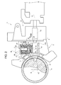
Figure 1 illustrates, schematically and in cross-section, a preferred embodiment of the steering lock device according to the present invention arranged in a normal operation condition; and -
Figures 2 and3 are figures similar toFigure 1 and illustrating the steering lock ofFigure 1 in two different functional conditions. - In
Figure 1 , number 1 indicates, as a whole, a steering lock for vehicles, comprising anouter housing 2, in turn, comprising afront collar portion 3 connected, in a per se known manner, to a fixed tubular body 4 crossed by asteering shaft 5 rotatable about its own axis 6. Thehousing 2 also comprises an intermediate hollow portion 7 and arear portion 8. - The
front portion 3 and intermediate portion 7 define in their inside arectilinear guide conduit 10, which extends in adirection 11 perpendicular to axis 6, and to which is coupled, in an axially sliding manner, alug 12, per se known, for angularly locking theshaft 5 with respect to the fixed tubular body 4. - The
lug 12 is movable under the thrust of an electric motor-reducer unit 13, per se known and not described in detail, permanently connected to therear portion 8 along thedirection 11 between a forward angular locking position, wherein afront end portion 12a of thelug 12 engages a retainingradial seat 14 formed on the steering shaft 5 (Figure 1 ), and a retracted rest position, illustrated with dotted line infigure 1 , wherein thelug 12 allows the free rotation of theshaft 5. - Again with reference to
Figure 1 , the steering lock 1 also comprises a tamper-proof device 15 activated by the rupture of theouter housing 2 and/or by the removal of the motor-reducer unit 13 and, in general, by the extraction of thelug 12 from theguide conduit 10, as illustrated inFigures 2 and3 . - The
device 15 is housed within thehousing 2 and, specifically, inside ancavity 16, which is elongated in adirection 18 perpendicular to thedirection 11 and to the axis 6 and communicates, on one side, with theguide conduit 10 and, on the other side, with the outside through a side opening 20 of the intermediate portion 7, closed by alid 21 connected integrally to the portion 7. - The
device 15 comprises aslide 22 housed in thecavity 16 and pushed in thedirection 18 towards theguide conduit 10 by a pair ofsprings 23 parallel to thedirection 18 itself and compressed between thelid 21, to which thesprings 23 are integrally connected, and anintermediate abutment wall 24 of theslide 22 parallel to thedirection 11. Thesprings 23 extend withinrespective guide sleeves 25 integral with theslide 22 and defining, with therespective springs 23, a guide and slide assembly for guiding theslide 22 in thedirection 18. - Again with reference to
Figure 2 , the tamper-proof device 15 further comprises an angular lockingadditional lug 27, which extends parallel to thelug 12 and to thedirection 11 and within acavity 29 of theslide 22. Thecavity 29 is open towards theconduit 10 and towards theportion 3 and is bounded by theintermediate wall 24 and by arear portion 30 perpendicular to thedirection 11. Theadditional lug 27 is adapted to engage theguide conduit 10 in axially sliding manner in the same way of thelug 12 and has a front end portion adapted to engage the retainingseat 14, as illustrated inFigure 3 . - Again with reference to
Figure 1 , theadditional lug 27 is maintained in contact with theintermediate wall 24 and theslide 22 is maintained in its retracted standby position (illustrated inFigures 1 and2 ) by thelug 12, which exerts a counter-action with respect to that of thesprings 23, and against which theadditional lug 27 is directly supported and slides, in use, during the displacement of thelug 12 between the forward position and the retracted position. When theslide 22 is arranged in its retracted standby position, the front portion of theadditional lug 27 is arranged in abutment against asurface 32 of thesupport portion 3 facing thewall 30 and the sameadditional lug 27 houses a forcedcompression spring 33 between theadditional lug 27 and thewall 30. In the particular example described, thecompression spring 33 slidingly engages ablind hole 34 for defining part of a guide and slide assembly adapted for guiding theadditional lug 27 in a direction parallel to thedirection 11. - Under normal conditions of use, the
lug 12 is displaced by the motor-reducer unit 13 between the aforementioned forward position and retracted position as in a conventional steering lock. In such conditions, theadditional lug 27 and theslide 22 are maintained in their retracted standby positions by thelug 12 itself. - When a break-in causes, for example, the rupture of the
outer housing 2 or the uncoupling of the motor-reducer unit 13 and, in general, the retraction of thelug 12 beyond its retracted position, i.e. outside the normal path between the forward position and the retracted position, the support of theadditional lug 27 on thelug 12 fails and, consequently, theslide 22 is forwarded by thesprings 23 towards theconduit 10 until engaging theadditional lug 27 itself inside theconduit 10. As soon as the support against thesurface 32 fails, theadditional lug 27 is pushed by thespring 33 towards theshaft 5 until theadditional lug 27 itself is brought to engagement with theseat 14. In this condition, theadditional lug 27 performs the same function as the main lug when the latter is in its forward position to prevent the rotation of thesteering shaft 5. - From the foregoing, it is evident that the steering lock 1 described allows in an extremely simple way to keep the steering shaft locked in any condition in which the
main lug 12 is arranged on the outside of its normal operative space. - The particular embodiment makes the tamper-
proof device 15 extremely efficient and reliable over time and is of simple and economical implementation and reduced dimensions. Furthermore, the particular embodiment of the tamper-proof device 15 allows a simple and immediate insertion inside thehousing 2 also facilitated by the presence of the side opening formed in the outer side part of thehousing 2. The fact of positioning theadditional lug 27 directly in contact with thelug 12 allows to reduce the size and geometry of the normal known steering locks when additional and/or dedicated components are avoided. Small overall dimensions and reduced costs are then consequent to the fact that thelug 12 and theadditional lug 27 share the same guide conduit to and from thesteering shaft 5. - From the above it is, finally, clear that the steering lock 1 described can be subject to modifications and variations without thereby departing from the protective scope defined by the independent claim. In particular, constructively different from the one described could be the
slide 22 and/or the pushing mode of theadditional lug 27 towards thetorsion shaft 5. - Furthermore, the same
additional lug 27 could have constructive characteristics different from those indicated and be, for example, coupled to theouter housing 2 in a different manner from that indicated. In particular, theadditional lug 27 could be hinged to theouter housing 2 and/or themain lug 12 acting indirectly to the maintenance of theadditional lug 27 in its standby position.
Claims (10)
- A steering lock for vehicles comprising an outer housing adapted to be blocked on a fixed body and at least partially surrounding a rotating steering shaft, a main member for angular locking of said steering shaft, actuator means for displacing said main member with respect to said housing between a forward operational position, in which the main member is partially inserted within a retaining seat borne by the steering shaft, and a retracted rest position, in which the main locking member allows the free rotation of said steering shaft, and tamper-proof means activated by the rupture of the outer housing or by the extraction of said main member, characterised in that said tamper-proof means comprise an angular locking additional member coupled to said outer housing and adapted to engage said retaining seat following the removal of said main angular member.
- The steering lock according to claim 1, characterised in that said tamper-proof means comprise retaining means for maintaining said additional member in a standby position spaced from said retaining seat when said main member is movable between said forward position and retracted position and elastic thrust means for pushing said additional element so as to engage said retaining seat following the displacement of said retaining main member outside the space in the range between said forward and retracted positions.
- The steering lock according to any of the preceding claims, characterised in that said main member and said additional member are housed in said housing in parallel positions.
- The steering lock according to claim 2, characterised in that said retaining means comprise said locking main member.
- The steering lock according to claim 4, characterised in that said main member slides in direct contact of said additional member when the additional locking member is arranged in said standby position.
- The steering lock according to claim 4 or 5, characterised in that said outer housing carries a rectilinear guide selectively and slidingly engaged by said locking members.
- The steering lock according to claim 6, characterised in that said tamper-proof means also comprise a movable frame for displacing said additional member, first elastic thrust means interposed between said outer housing and said movable frame for pushing said additional element towards said rectilinear guide and second elastic means interposed between said movable frame and said additional element for pushing said additional element in a direction parallel to said rectilinear guide towards said retaining seat.
- The steering lock according to claim 7, characterised by comprising a first guide and slide assembly for guiding said frame in a direction orthogonal to said rectilinear guide, and a second guide and slide assembly interposed between said movable frame and said additional member for guiding said additional member in a direction coinciding with the displacement direction of said main member.
- The steering lock according to claim 8, characterised in that said first and second elastic thrust means define the guides of the first and, respectively, of the second guide and slide assembly.
- The steering lock according to any of the preceding claims, characterised in that said outer housing has a side opening for inserting from outside said tamper-proof device; the tamper-proof device comprising a lid for closing said opening and stably connected to said outer housing.
Priority Applications (1)
| Application Number | Priority Date | Filing Date | Title |
|---|---|---|---|
| PL13164017T PL2653357T3 (en) | 2012-04-16 | 2013-04-16 | Steering lock for vehicles |
Applications Claiming Priority (1)
| Application Number | Priority Date | Filing Date | Title |
|---|---|---|---|
| IT000329A ITTO20120329A1 (en) | 2012-04-16 | 2012-04-16 | STEERING LOCK FOR VEHICLES |
Publications (2)
| Publication Number | Publication Date |
|---|---|
| EP2653357A1 true EP2653357A1 (en) | 2013-10-23 |
| EP2653357B1 EP2653357B1 (en) | 2015-03-11 |
Family
ID=46262247
Family Applications (1)
| Application Number | Title | Priority Date | Filing Date |
|---|---|---|---|
| EP13164017.9A Not-in-force EP2653357B1 (en) | 2012-04-16 | 2013-04-16 | Steering lock for vehicles |
Country Status (7)
| Country | Link |
|---|---|
| EP (1) | EP2653357B1 (en) |
| CN (1) | CN103373315B (en) |
| ES (1) | ES2534102T3 (en) |
| IT (1) | ITTO20120329A1 (en) |
| PL (1) | PL2653357T3 (en) |
| PT (1) | PT2653357E (en) |
| RS (1) | RS53969B1 (en) |
Cited By (1)
| Publication number | Priority date | Publication date | Assignee | Title |
|---|---|---|---|---|
| JP2017124724A (en) * | 2016-01-13 | 2017-07-20 | 株式会社ホンダロック | Electric steering lock device |
Citations (4)
| Publication number | Priority date | Publication date | Assignee | Title |
|---|---|---|---|---|
| WO1983003580A1 (en) * | 1982-04-14 | 1983-10-27 | Weber, Günter | Device for locking the rotation motion of a steering shaft of a motor vehicle |
| EP0219002A2 (en) * | 1985-10-09 | 1987-04-22 | Neiman | Device for blocking the rotational motion of a vehicle's steering column |
| US5635899A (en) * | 1994-10-17 | 1997-06-03 | Winner International Royalty Corporation | Vehicle anti-theft device and system |
| EP1688327B1 (en) * | 2005-02-07 | 2008-07-02 | Valeo Sicherheitssysteme GmbH | Locking device for a steering shaft |
Family Cites Families (1)
| Publication number | Priority date | Publication date | Assignee | Title |
|---|---|---|---|---|
| FR2909952B1 (en) * | 2006-12-19 | 2009-03-20 | Valeo Securite Habitacle Sas | VEHICLE ANTI-THEFT COMPRISING A EQUIPPED HOUSING AND METHOD OF MAKING SAID HOUSING. |
-
2012
- 2012-04-16 IT IT000329A patent/ITTO20120329A1/en unknown
-
2013
- 2013-04-16 EP EP13164017.9A patent/EP2653357B1/en not_active Not-in-force
- 2013-04-16 PT PT131640179T patent/PT2653357E/en unknown
- 2013-04-16 PL PL13164017T patent/PL2653357T3/en unknown
- 2013-04-16 CN CN201310130538.XA patent/CN103373315B/en not_active Expired - Fee Related
- 2013-04-16 RS RS20150277A patent/RS53969B1/en unknown
- 2013-04-16 ES ES13164017.9T patent/ES2534102T3/en active Active
Patent Citations (4)
| Publication number | Priority date | Publication date | Assignee | Title |
|---|---|---|---|---|
| WO1983003580A1 (en) * | 1982-04-14 | 1983-10-27 | Weber, Günter | Device for locking the rotation motion of a steering shaft of a motor vehicle |
| EP0219002A2 (en) * | 1985-10-09 | 1987-04-22 | Neiman | Device for blocking the rotational motion of a vehicle's steering column |
| US5635899A (en) * | 1994-10-17 | 1997-06-03 | Winner International Royalty Corporation | Vehicle anti-theft device and system |
| EP1688327B1 (en) * | 2005-02-07 | 2008-07-02 | Valeo Sicherheitssysteme GmbH | Locking device for a steering shaft |
Cited By (1)
| Publication number | Priority date | Publication date | Assignee | Title |
|---|---|---|---|---|
| JP2017124724A (en) * | 2016-01-13 | 2017-07-20 | 株式会社ホンダロック | Electric steering lock device |
Also Published As
| Publication number | Publication date |
|---|---|
| RS53969B1 (en) | 2015-08-31 |
| PT2653357E (en) | 2015-05-12 |
| PL2653357T3 (en) | 2015-08-31 |
| EP2653357B1 (en) | 2015-03-11 |
| CN103373315A (en) | 2013-10-30 |
| ITTO20120329A1 (en) | 2013-10-17 |
| ES2534102T3 (en) | 2015-04-17 |
| CN103373315B (en) | 2017-03-01 |
Similar Documents
| Publication | Publication Date | Title |
|---|---|---|
| US9403489B2 (en) | Vehicle dashboard provided with a portable electronic device | |
| ES2699675T3 (en) | Device for controlled retention or release of a mobile component relevant for safety | |
| JP6110333B2 (en) | Vehicle parking lock release device | |
| EP2980343B1 (en) | Door handle apparatus for vehicle | |
| KR101504450B1 (en) | Steering lock device | |
| EP2653357B1 (en) | Steering lock for vehicles | |
| CN105636837B (en) | Burglary-resisting installation for motor vehicle steering column | |
| CN108005475B (en) | Mechanical separation type handle lock | |
| JP5037486B2 (en) | Releasable lock for automotive locking system | |
| CN109890251B (en) | Push-out device for movable furniture part, furniture and method for opening movable furniture part | |
| EP3640097B1 (en) | Steering lock device | |
| RU2583423C2 (en) | Antitheft device for steering column and corresponding steering column | |
| JP5989507B2 (en) | Lid lock device | |
| US9827948B2 (en) | Anti-theft device for a steering column of a motor vehicle | |
| EP2821571B1 (en) | Locking mechanism, opening system and motor vehicle | |
| JP5722724B2 (en) | Safety switch | |
| CN105839995B (en) | A kind of tapered end and its lock pin | |
| JP6169731B2 (en) | Steering lock device for automobile | |
| CN105764757B (en) | Mechanical steering for vehicle is locked | |
| WO2021110572A1 (en) | Aircraft door with retraction of the means for retaining the deployable evacuation device | |
| EP4399126B1 (en) | Device for locking a roller blind cassette on a trunk of a vehicle | |
| EP3241962B1 (en) | Latch lock with a modifiable opening direction | |
| JP6486448B2 (en) | Steering lock device | |
| WO2013136297A2 (en) | Key lock for vehicles | |
| CN102747868B (en) | Anti-theft control mechanism of anti-theft lock |
Legal Events
| Date | Code | Title | Description |
|---|---|---|---|
| PUAI | Public reference made under article 153(3) epc to a published international application that has entered the european phase |
Free format text: ORIGINAL CODE: 0009012 |
|
| AK | Designated contracting states |
Kind code of ref document: A1 Designated state(s): AL AT BE BG CH CY CZ DE DK EE ES FI FR GB GR HR HU IE IS IT LI LT LU LV MC MK MT NL NO PL PT RO RS SE SI SK SM TR |
|
| AX | Request for extension of the european patent |
Extension state: BA ME |
|
| 17P | Request for examination filed |
Effective date: 20140423 |
|
| RBV | Designated contracting states (corrected) |
Designated state(s): AL AT BE BG CH CY CZ DE DK EE ES FI FR GB GR HR HU IE IS IT LI LT LU LV MC MK MT NL NO PL PT RO RS SE SI SK SM TR |
|
| GRAP | Despatch of communication of intention to grant a patent |
Free format text: ORIGINAL CODE: EPIDOSNIGR1 |
|
| INTG | Intention to grant announced |
Effective date: 20140930 |
|
| GRAS | Grant fee paid |
Free format text: ORIGINAL CODE: EPIDOSNIGR3 |
|
| GRAA | (expected) grant |
Free format text: ORIGINAL CODE: 0009210 |
|
| AK | Designated contracting states |
Kind code of ref document: B1 Designated state(s): AL AT BE BG CH CY CZ DE DK EE ES FI FR GB GR HR HU IE IS IT LI LT LU LV MC MK MT NL NO PL PT RO RS SE SI SK SM TR |
|
| REG | Reference to a national code |
Ref country code: GB Ref legal event code: FG4D |
|
| REG | Reference to a national code |
Ref country code: CH Ref legal event code: EP |
|
| REG | Reference to a national code |
Ref country code: IE Ref legal event code: FG4D |
|
| REG | Reference to a national code |
Ref country code: AT Ref legal event code: REF Ref document number: 715127 Country of ref document: AT Kind code of ref document: T Effective date: 20150415 |
|
| REG | Reference to a national code |
Ref country code: ES Ref legal event code: FG2A Ref document number: 2534102 Country of ref document: ES Kind code of ref document: T3 Effective date: 20150417 |
|
| REG | Reference to a national code |
Ref country code: DE Ref legal event code: R096 Ref document number: 602013001150 Country of ref document: DE Effective date: 20150423 |
|
| REG | Reference to a national code |
Ref country code: RO Ref legal event code: EPE |
|
| REG | Reference to a national code |
Ref country code: PT Ref legal event code: SC4A Free format text: AVAILABILITY OF NATIONAL TRANSLATION Effective date: 20150414 |
|
| REG | Reference to a national code |
Ref country code: NL Ref legal event code: VDEP Effective date: 20150311 |
|
| REG | Reference to a national code |
Ref country code: NL Ref legal event code: VDEP Effective date: 20150311 |
|
| PG25 | Lapsed in a contracting state [announced via postgrant information from national office to epo] |
Ref country code: FI Free format text: LAPSE BECAUSE OF FAILURE TO SUBMIT A TRANSLATION OF THE DESCRIPTION OR TO PAY THE FEE WITHIN THE PRESCRIBED TIME-LIMIT Effective date: 20150311 Ref country code: LT Free format text: LAPSE BECAUSE OF FAILURE TO SUBMIT A TRANSLATION OF THE DESCRIPTION OR TO PAY THE FEE WITHIN THE PRESCRIBED TIME-LIMIT Effective date: 20150311 Ref country code: SE Free format text: LAPSE BECAUSE OF FAILURE TO SUBMIT A TRANSLATION OF THE DESCRIPTION OR TO PAY THE FEE WITHIN THE PRESCRIBED TIME-LIMIT Effective date: 20150311 Ref country code: NO Free format text: LAPSE BECAUSE OF FAILURE TO SUBMIT A TRANSLATION OF THE DESCRIPTION OR TO PAY THE FEE WITHIN THE PRESCRIBED TIME-LIMIT Effective date: 20150611 Ref country code: HR Free format text: LAPSE BECAUSE OF FAILURE TO SUBMIT A TRANSLATION OF THE DESCRIPTION OR TO PAY THE FEE WITHIN THE PRESCRIBED TIME-LIMIT Effective date: 20150311 |
|
| REG | Reference to a national code |
Ref country code: AT Ref legal event code: MK05 Ref document number: 715127 Country of ref document: AT Kind code of ref document: T Effective date: 20150311 |
|
| REG | Reference to a national code |
Ref country code: LT Ref legal event code: MG4D |
|
| PG25 | Lapsed in a contracting state [announced via postgrant information from national office to epo] |
Ref country code: GR Free format text: LAPSE BECAUSE OF FAILURE TO SUBMIT A TRANSLATION OF THE DESCRIPTION OR TO PAY THE FEE WITHIN THE PRESCRIBED TIME-LIMIT Effective date: 20150612 Ref country code: LV Free format text: LAPSE BECAUSE OF FAILURE TO SUBMIT A TRANSLATION OF THE DESCRIPTION OR TO PAY THE FEE WITHIN THE PRESCRIBED TIME-LIMIT Effective date: 20150311 |
|
| REG | Reference to a national code |
Ref country code: PL Ref legal event code: T3 |
|
| REG | Reference to a national code |
Ref country code: SK Ref legal event code: T3 Ref document number: E 18760 Country of ref document: SK |
|
| PG25 | Lapsed in a contracting state [announced via postgrant information from national office to epo] |
Ref country code: NL Free format text: LAPSE BECAUSE OF FAILURE TO SUBMIT A TRANSLATION OF THE DESCRIPTION OR TO PAY THE FEE WITHIN THE PRESCRIBED TIME-LIMIT Effective date: 20150311 |
|
| PG25 | Lapsed in a contracting state [announced via postgrant information from national office to epo] |
Ref country code: EE Free format text: LAPSE BECAUSE OF FAILURE TO SUBMIT A TRANSLATION OF THE DESCRIPTION OR TO PAY THE FEE WITHIN THE PRESCRIBED TIME-LIMIT Effective date: 20150311 |
|
| PG25 | Lapsed in a contracting state [announced via postgrant information from national office to epo] |
Ref country code: MC Free format text: LAPSE BECAUSE OF FAILURE TO SUBMIT A TRANSLATION OF THE DESCRIPTION OR TO PAY THE FEE WITHIN THE PRESCRIBED TIME-LIMIT Effective date: 20150311 Ref country code: IS Free format text: LAPSE BECAUSE OF FAILURE TO SUBMIT A TRANSLATION OF THE DESCRIPTION OR TO PAY THE FEE WITHIN THE PRESCRIBED TIME-LIMIT Effective date: 20150711 Ref country code: AT Free format text: LAPSE BECAUSE OF FAILURE TO SUBMIT A TRANSLATION OF THE DESCRIPTION OR TO PAY THE FEE WITHIN THE PRESCRIBED TIME-LIMIT Effective date: 20150311 |
|
| REG | Reference to a national code |
Ref country code: DE Ref legal event code: R097 Ref document number: 602013001150 Country of ref document: DE |
|
| PG25 | Lapsed in a contracting state [announced via postgrant information from national office to epo] |
Ref country code: IT Free format text: LAPSE BECAUSE OF FAILURE TO SUBMIT A TRANSLATION OF THE DESCRIPTION OR TO PAY THE FEE WITHIN THE PRESCRIBED TIME-LIMIT Effective date: 20150311 |
|
| PLBE | No opposition filed within time limit |
Free format text: ORIGINAL CODE: 0009261 |
|
| STAA | Information on the status of an ep patent application or granted ep patent |
Free format text: STATUS: NO OPPOSITION FILED WITHIN TIME LIMIT |
|
| REG | Reference to a national code |
Ref country code: IE Ref legal event code: MM4A |
|
| PG25 | Lapsed in a contracting state [announced via postgrant information from national office to epo] |
Ref country code: DK Free format text: LAPSE BECAUSE OF FAILURE TO SUBMIT A TRANSLATION OF THE DESCRIPTION OR TO PAY THE FEE WITHIN THE PRESCRIBED TIME-LIMIT Effective date: 20150311 |
|
| 26N | No opposition filed |
Effective date: 20151214 |
|
| PG25 | Lapsed in a contracting state [announced via postgrant information from national office to epo] |
Ref country code: SI Free format text: LAPSE BECAUSE OF FAILURE TO SUBMIT A TRANSLATION OF THE DESCRIPTION OR TO PAY THE FEE WITHIN THE PRESCRIBED TIME-LIMIT Effective date: 20150311 |
|
| REG | Reference to a national code |
Ref country code: FR Ref legal event code: PLFP Year of fee payment: 4 |
|
| PG25 | Lapsed in a contracting state [announced via postgrant information from national office to epo] |
Ref country code: IE Free format text: LAPSE BECAUSE OF NON-PAYMENT OF DUE FEES Effective date: 20150416 |
|
| PG25 | Lapsed in a contracting state [announced via postgrant information from national office to epo] |
Ref country code: BE Free format text: LAPSE BECAUSE OF FAILURE TO SUBMIT A TRANSLATION OF THE DESCRIPTION OR TO PAY THE FEE WITHIN THE PRESCRIBED TIME-LIMIT Effective date: 20150311 |
|
| REG | Reference to a national code |
Ref country code: CH Ref legal event code: PL |
|
| PG25 | Lapsed in a contracting state [announced via postgrant information from national office to epo] |
Ref country code: MT Free format text: LAPSE BECAUSE OF FAILURE TO SUBMIT A TRANSLATION OF THE DESCRIPTION OR TO PAY THE FEE WITHIN THE PRESCRIBED TIME-LIMIT Effective date: 20150311 |
|
| PG25 | Lapsed in a contracting state [announced via postgrant information from national office to epo] |
Ref country code: LI Free format text: LAPSE BECAUSE OF NON-PAYMENT OF DUE FEES Effective date: 20160430 Ref country code: CH Free format text: LAPSE BECAUSE OF NON-PAYMENT OF DUE FEES Effective date: 20160430 |
|
| REG | Reference to a national code |
Ref country code: FR Ref legal event code: PLFP Year of fee payment: 5 |
|
| PG25 | Lapsed in a contracting state [announced via postgrant information from national office to epo] |
Ref country code: HU Free format text: LAPSE BECAUSE OF FAILURE TO SUBMIT A TRANSLATION OF THE DESCRIPTION OR TO PAY THE FEE WITHIN THE PRESCRIBED TIME-LIMIT; INVALID AB INITIO Effective date: 20130416 Ref country code: BG Free format text: LAPSE BECAUSE OF FAILURE TO SUBMIT A TRANSLATION OF THE DESCRIPTION OR TO PAY THE FEE WITHIN THE PRESCRIBED TIME-LIMIT Effective date: 20150311 |
|
| PG25 | Lapsed in a contracting state [announced via postgrant information from national office to epo] |
Ref country code: CY Free format text: LAPSE BECAUSE OF FAILURE TO SUBMIT A TRANSLATION OF THE DESCRIPTION OR TO PAY THE FEE WITHIN THE PRESCRIBED TIME-LIMIT Effective date: 20150311 |
|
| PG25 | Lapsed in a contracting state [announced via postgrant information from national office to epo] |
Ref country code: LU Free format text: LAPSE BECAUSE OF NON-PAYMENT OF DUE FEES Effective date: 20150416 |
|
| REG | Reference to a national code |
Ref country code: FR Ref legal event code: PLFP Year of fee payment: 6 |
|
| PG25 | Lapsed in a contracting state [announced via postgrant information from national office to epo] |
Ref country code: SM Free format text: LAPSE BECAUSE OF FAILURE TO SUBMIT A TRANSLATION OF THE DESCRIPTION OR TO PAY THE FEE WITHIN THE PRESCRIBED TIME-LIMIT Effective date: 20150311 |
|
| REG | Reference to a national code |
Ref country code: DE Ref legal event code: R082 Ref document number: 602013001150 Country of ref document: DE Representative=s name: PRINZ & PARTNER MBB PATENTANWAELTE RECHTSANWAE, DE |
|
| PG25 | Lapsed in a contracting state [announced via postgrant information from national office to epo] |
Ref country code: MK Free format text: LAPSE BECAUSE OF FAILURE TO SUBMIT A TRANSLATION OF THE DESCRIPTION OR TO PAY THE FEE WITHIN THE PRESCRIBED TIME-LIMIT Effective date: 20150311 |
|
| REG | Reference to a national code |
Ref country code: DE Ref legal event code: R082 Ref document number: 602013001150 Country of ref document: DE Representative=s name: PRINZ & PARTNER MBB PATENTANWAELTE RECHTSANWAE, DE |
|
| PGFP | Annual fee paid to national office [announced via postgrant information from national office to epo] |
Ref country code: PT Payment date: 20180403 Year of fee payment: 6 Ref country code: ES Payment date: 20180503 Year of fee payment: 6 Ref country code: SK Payment date: 20180404 Year of fee payment: 6 Ref country code: CZ Payment date: 20180409 Year of fee payment: 6 |
|
| PGFP | Annual fee paid to national office [announced via postgrant information from national office to epo] |
Ref country code: FR Payment date: 20180420 Year of fee payment: 11 Ref country code: RS Payment date: 20180413 Year of fee payment: 6 Ref country code: TR Payment date: 20180403 Year of fee payment: 6 Ref country code: RO Payment date: 20180403 Year of fee payment: 6 |
|
| PG25 | Lapsed in a contracting state [announced via postgrant information from national office to epo] |
Ref country code: AL Free format text: LAPSE BECAUSE OF FAILURE TO SUBMIT A TRANSLATION OF THE DESCRIPTION OR TO PAY THE FEE WITHIN THE PRESCRIBED TIME-LIMIT Effective date: 20150311 |
|
| PGFP | Annual fee paid to national office [announced via postgrant information from national office to epo] |
Ref country code: DE Payment date: 20190416 Year of fee payment: 7 |
|
| REG | Reference to a national code |
Ref country code: DE Ref legal event code: R082 Ref document number: 602013001150 Country of ref document: DE Representative=s name: PRINZ & PARTNER MBB PATENTANWAELTE RECHTSANWAE, DE Ref country code: DE Ref legal event code: R081 Ref document number: 602013001150 Country of ref document: DE Owner name: BCS AUTOMOTIVE INTERFACE SOLUTIONS ITALY S.R.L, IT Free format text: FORMER OWNER: TRW AUTOMOTIVE ITALIA S.R.L., TORINO, IT |
|
| PGFP | Annual fee paid to national office [announced via postgrant information from national office to epo] |
Ref country code: GB Payment date: 20190418 Year of fee payment: 7 |
|
| REG | Reference to a national code |
Ref country code: SK Ref legal event code: MM4A Ref document number: E 18760 Country of ref document: SK Effective date: 20190416 |
|
| PG25 | Lapsed in a contracting state [announced via postgrant information from national office to epo] |
Ref country code: RO Free format text: LAPSE BECAUSE OF NON-PAYMENT OF DUE FEES Effective date: 20190416 Ref country code: CZ Free format text: LAPSE BECAUSE OF NON-PAYMENT OF DUE FEES Effective date: 20190416 Ref country code: PT Free format text: LAPSE BECAUSE OF NON-PAYMENT OF DUE FEES Effective date: 20191016 Ref country code: SK Free format text: LAPSE BECAUSE OF NON-PAYMENT OF DUE FEES Effective date: 20190416 |
|
| PG25 | Lapsed in a contracting state [announced via postgrant information from national office to epo] |
Ref country code: RS Free format text: LAPSE BECAUSE OF NON-PAYMENT OF DUE FEES Effective date: 20191031 |
|
| REG | Reference to a national code |
Ref country code: ES Ref legal event code: FD2A Effective date: 20200831 |
|
| PG25 | Lapsed in a contracting state [announced via postgrant information from national office to epo] |
Ref country code: ES Free format text: LAPSE BECAUSE OF NON-PAYMENT OF DUE FEES Effective date: 20190417 |
|
| REG | Reference to a national code |
Ref country code: DE Ref legal event code: R119 Ref document number: 602013001150 Country of ref document: DE |
|
| PG25 | Lapsed in a contracting state [announced via postgrant information from national office to epo] |
Ref country code: FR Free format text: LAPSE BECAUSE OF NON-PAYMENT OF DUE FEES Effective date: 20200430 Ref country code: DE Free format text: LAPSE BECAUSE OF NON-PAYMENT OF DUE FEES Effective date: 20201103 |
|
| GBPC | Gb: european patent ceased through non-payment of renewal fee |
Effective date: 20200416 |
|
| PG25 | Lapsed in a contracting state [announced via postgrant information from national office to epo] |
Ref country code: GB Free format text: LAPSE BECAUSE OF NON-PAYMENT OF DUE FEES Effective date: 20200416 |
|
| PG25 | Lapsed in a contracting state [announced via postgrant information from national office to epo] |
Ref country code: PL Free format text: LAPSE BECAUSE OF NON-PAYMENT OF DUE FEES Effective date: 20190416 |
|
| PG25 | Lapsed in a contracting state [announced via postgrant information from national office to epo] |
Ref country code: TR Free format text: LAPSE BECAUSE OF NON-PAYMENT OF DUE FEES Effective date: 20190416 |