EP2653254A2 - Workpiece holder for holding a plurality of plate-like workpieces used for wire electric discharge machine - Google Patents
Workpiece holder for holding a plurality of plate-like workpieces used for wire electric discharge machine Download PDFInfo
- Publication number
- EP2653254A2 EP2653254A2 EP13157283.6A EP13157283A EP2653254A2 EP 2653254 A2 EP2653254 A2 EP 2653254A2 EP 13157283 A EP13157283 A EP 13157283A EP 2653254 A2 EP2653254 A2 EP 2653254A2
- Authority
- EP
- European Patent Office
- Prior art keywords
- plate
- workpieces
- electric discharge
- wire electric
- cylindrical member
- Prior art date
- Legal status (The legal status is an assumption and is not a legal conclusion. Google has not performed a legal analysis and makes no representation as to the accuracy of the status listed.)
- Granted
Links
Images




Classifications
-
- B—PERFORMING OPERATIONS; TRANSPORTING
- B23—MACHINE TOOLS; METAL-WORKING NOT OTHERWISE PROVIDED FOR
- B23H—WORKING OF METAL BY THE ACTION OF A HIGH CONCENTRATION OF ELECTRIC CURRENT ON A WORKPIECE USING AN ELECTRODE WHICH TAKES THE PLACE OF A TOOL; SUCH WORKING COMBINED WITH OTHER FORMS OF WORKING OF METAL
- B23H11/00—Auxiliary apparatus or details, not otherwise provided for
- B23H11/003—Mounting of workpieces, e.g. working-tables
-
- B—PERFORMING OPERATIONS; TRANSPORTING
- B23—MACHINE TOOLS; METAL-WORKING NOT OTHERWISE PROVIDED FOR
- B23H—WORKING OF METAL BY THE ACTION OF A HIGH CONCENTRATION OF ELECTRIC CURRENT ON A WORKPIECE USING AN ELECTRODE WHICH TAKES THE PLACE OF A TOOL; SUCH WORKING COMBINED WITH OTHER FORMS OF WORKING OF METAL
- B23H7/00—Processes or apparatus applicable to both electrical discharge machining and electrochemical machining
- B23H7/02—Wire-cutting
Definitions
- the present invention relates to a plate-like workpiece holder used for a wire electric discharge machine when stacked workpieces are machined to reduce machining time per workpiece.
- Japanese Patent Application Laid-Open No. 6-47625 discloses a securing tool for stack cutting that secures, in a tightening manner, upper and lower metal plates to a machining workpiece stage with a plurality of securing bolts.
- a force to hold stacked plate-like workpieces is applied only in a vertical direction (Z-axis direction). However, there is no force that holds these stacked plate-like workpieces in a horizontal direction (X-axis direction) or an anteroposterior direction (Y-axis direction), so the stacked workpieces deviate. If the stacked plate-like workpieces are held in the horizontal direction (X-axis direction) or the anteroposterior direction (Y-axis direction), the stacked plate-like workpieces are deformed by the holding force and the space between the stacked plate-like workpieces is generated, thereby causing a wire break as described above. In addition, a wire electric discharge machine cannot be used until the plurality of plate-like workpieces are secured to the wire electric discharge machine, so the availability rate of the wire electric discharge machine is reduced.
- the securing tool for stack cutting disclosed in the above Japanese Patent Application Laid-Open No. 6-47625 secures the upper and lower metals plates to the machining workpiece stage using the plurality of securing bolts, so the tightening force is unlikely to become even in some places, a space is generated between stacked upper and lower metal sheets, the speed of electric discharge machining is different between the stacked upper and lower metal sheets, or the tightening force of securing bolts becomes uneven as the cutting position in an object to be machined advances during electric discharge machining by the wire electrode.
- the object of the present invention is, in view of the above problems of the prior art technique, to provide a workpiece holder for holding a plurality of plate-like workpieces used for a wire electric discharge machine that can hold the plurality plate-like workpieces precisely in close contact with each other when the plurality plate-like workpieces are held in a stacked state, and can perform efficient wire electric discharge machining.
- the present invention relates to a plate-like workpiece holder for holding a plurality of plate-like workpieces used for a wire electric discharge machine, wherein the wire electric discharge machine relatively moves a wire electrode stretched between upper and lower wire guides with respect to the plurality of plate-like workpieces stacked on a workpiece stage so as to machine the plurality of plate-like workpieces stacked.
- the workpiece holder for holding the plurality of plate-like workpieces stacked includes: a cylindrical member in which the plurality of plate-like workpieces are held in a stacked state and which has an inner circumference surface where concave sections corresponding to a machining start point and a machining end point are provided; lid members that are mounted on an upper end and a lower end of the cylindrical member to press the plurality of plate-like workpieces; and a workpiece stage mount member which is secured to the workpiece stage and which has an insertion hole in which the cylindrical member is inserted and housed.
- a projection or an elastic member that holds the plurality of plate-like workpieces may be provided in a predetermined position on the inner circumference surface of the cylindrical member.
- a projection or an elastic member that holds the plurality of plate-like workpieces may be provided on surfaces of the lid members that face the plurality of plate-like workpieces.
- Each of the lid members may be divided according to a machining path of the plurality of plate-like workpieces.
- a workpiece holder for holding a plurality of plate-like workpieces used for a wire electric discharge machine that can hold the plurality of plate-like workpieces precisely in close contact with each other when the plurality plate-like workpieces are held in a stacked state and can perform efficient wire electric discharge machining.
- a plate-like workpiece holder according to an embodiment of the present invention will be described with reference to Figs. 1A to 4B .
- FIGs. 1A and 1B show an example of one plate-like workpiece.
- a plate-like workpiece 2 is a substantially rectangular thin-plate with a hole 3 at the center thereof as shown in the plan view in Fig. 1A and upper, and lower surfaces of which are parallel to each other as shown in Fig. 1B .
- the workpiece holder for holding a plurality of the plate-like workpieces shown in Figs. 1A (plan view) and 1B (side view) includes a cylindrical member 10 (see Figs. 2A and 2B ), upper and lower lid members 20 (see Figs. 3A to 3C ), and a workpiece stage mount member 30 (see Figs. 4A and 4B ).
- This workpiece holder is used for wire electric discharge machines.
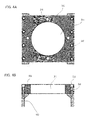
- Fig. 2A is a top view and Fig. 2B is a cross-sectional view taken along a dashed line 18.
- the cylindrical member 10 includes a through hole 11 in which the plurality of plate-like workpieces 2 are inserted and housed, a flange 14 for supporting the cylindrical member 10 via the workpiece stage mount member 30 (described later), bolt holes 15 into which securing bolts 5 (see Fig. 8A ) are inserted, bolt holes 17 into which securing bolts 7 (see Fig. 8A ) are inserted, and an insertion section 16, which is inserted into an insertion hole 31 of the workpiece stage mount member 30.
- Concave sections 12 and 13 are disposed in positions that correspond to the machining start point and the machining end point of wire electric discharge machining, respectively, on an inner circumference surface of the through hole 11.
- Fig. 3A is a top view of the lid member 20
- Fig. 3B is a side view of the lid member 20 secured to the upper surface of the cylindrical member 10 with the securing bolts 5
- Fig. 3C is a side view of the lid member 20 secured to the lower surface of the cylindrical member 10 with the securing bolts 5.
- the lid members 20 are placed on the upper end and lower end of the cylindrical member 10 in which the plurality of plate-like workpieces 2 are housed so as to press the upper end and the lower end of the plate-like workpieces 2.
- the lid member 20 mounted on the upper surface of the cylindrical member 10 includes a member 20a and a member 20b, which are symmetrical.
- the lid member 20 mounted on the lower surface of the cylindrical member 10 includes a member 20c and a member 20d, which are symmetrical.
- these members 20a, 20b, 20c, and 20d included in the lid members 20 have the same shape, and bolt holes 21 that correspond to the bolt holes 15 disposed in the cylindrical member 10 are provided in the members 20a, 20b, 20c, and 20d, respectively. Insertion of the securing bolts 5 (see Fig. 8A ) into the bolt holes 15 and the bolt holes 21 can secure the upper lid member 20 and the lower lid member 20 to the upper surface and the lower surface of the cylindrical member 10, respectively.
- the cylindrical member 10 to prevent the plurality of plate-like workpieces 2 from moving in the anteroposterior direction or in the horizontal direction and causes the upper and lower lid members 20 to prevent the plurality of plate-like workpieces 2 from moving in the vertical direction.
- the plate-like workpieces 2 may be held by providing a projection or an elastic member on surfaces of the cylindrical member 10 and the lid members 20 that face the plate-like workpieces 2.
- the projection or elastic member to be provided may be detachable.
- Fig. 4A is a top view as viewed from above and Fig. 4B is a cross-sectional view of the workpiece stage mount member of Fig. 4A .
- the workpiece stage mount member 30 has the insertion hole 31 into which the insertion section 16 of the cylindrical member 10 is inserted, bolt holes 33 into which securing bolts 32 are screwed, and bolt holes 34 into which the securing bolts 7 to be screwed into bolt holes 17 formed in the flange 14 of the cylindrical member 10 are screwed.
- the workpiece stage mount member 30 is secured to a workpiece stage 40 of the machine body (not shown) of a wire electric discharge machine with the securing bolts 32, as shown in Fig. 4B .
- the workpiece holder includes the cylindrical member 10, the upper and lower lid members 20, and the workpiece stage mount member 30.
- the cylindrical member 10 houses a plurality of plate-like workpieces 2 and holds the ends of these plate-like workpieces 2 in their horizontal direction and anteroposterior direction
- the upper and lower lid members 20 holds the upper and lower ends of the plurality of plate-like workpieces 2 housed in the cylindrical member 10
- the workpiece stage mount member 30 secures the cylindrical member 10 that has housed the plurality of plate-like workpieces 2 to the lid members 20 placed on the upper and lower ends of the plurality of plate-like workpieces 2.
- the plurality of plate-like workpieces 2 are stacked and inserted into the through hole 11 of the cylindrical member 10 (see the arrow in Fig. 5B ).
- the lid members 20 are placed on the upper end and the lower end of the plurality of plate-like workpieces 2 housed in the through hole 11 of the cylindrical member 10 so as to press the upper end and the lower end of the plurality of plate-like workpieces 2 (see the arrows in Fig. 6B ). This holds the ends in the horizontal direction, the anteroposterior direction, and vertical direction of the plurality of the plate-like workpieces 2 stacked (see the arrows in Fig. 6B ).
- wire electric discharge machining is started upon completion of connection of a wire electrode 46 passing through an upper nozzle 42 of an upper guide part and a lower nozzle 44 of a lower guide part.
- wire electric discharge machining is completed when wire electric discharge machining proceeds and reaches the concave section 13 formed in a position that corresponds to the machining end point of wire electric discharge machining on the inner circumference surface of the through hole 11 of the cylindrical member 10, the wire electrode 46 is cut in this position.
- the cylindrical member 10 that holds the plurality of plate-like workpieces 2 for which electric discharge machining was completed and the lid members 20 are removed from the workpiece stage mount member 30.
- the cylindrical member 10 that holds the plurality of plate-like workpieces 2 and the lid members 20 may be mounted on the workpiece stage mount member 30 secured in advance to a different position on the workpiece stage 40, and, as in the above case, the X-axis and Y-axis of the wire electric discharge machine may be moved to the concave section 12 (see Fig. 8A ) formed in a position that corresponds to the machining start point of wire electric discharge machining on the inner circumference surface of the through hole 11 of the mounted cylindrical member 10 in order to perform wire electric discharge machining.
- the workpiece holder of the present invention that holds a plurality of plate-like workpieces, used for electric discharge machines, has the following effects more advantageous than the prior art.
Landscapes
- Engineering & Computer Science (AREA)
- Mechanical Engineering (AREA)
- Electrical Discharge Machining, Electrochemical Machining, And Combined Machining (AREA)
Abstract
Description
- The present invention relates to a plate-like workpiece holder used for a wire electric discharge machine when stacked workpieces are machined to reduce machining time per workpiece.
- When a plurality of plate-like workpieces are machined by a wire electric discharge machine, if the plurality of plate-like workpieces stacked are machined, the machining time per workpiece can be reduced. However, when the plurality of workpieces stacked are secured, the machining time or machining precision may be adversely affected depending on the method of securing the plurality of workpieces. Accordingly, the plurality of workpieces need to be secured to prevent a generation of space between workpieces that causes a wire break during wire electric discharge machining or reduction in the machining precision. For example, Japanese Patent Application Laid-Open No.
6-47625 - A force to hold stacked plate-like workpieces is applied only in a vertical direction (Z-axis direction). However, there is no force that holds these stacked plate-like workpieces in a horizontal direction (X-axis direction) or an anteroposterior direction (Y-axis direction), so the stacked workpieces deviate. If the stacked plate-like workpieces are held in the horizontal direction (X-axis direction) or the anteroposterior direction (Y-axis direction), the stacked plate-like workpieces are deformed by the holding force and the space between the stacked plate-like workpieces is generated, thereby causing a wire break as described above. In addition, a wire electric discharge machine cannot be used until the plurality of plate-like workpieces are secured to the wire electric discharge machine, so the availability rate of the wire electric discharge machine is reduced.
- The securing tool for stack cutting disclosed in the above Japanese Patent Application Laid-Open No.
6-47625 - The object of the present invention is, in view of the above problems of the prior art technique, to provide a workpiece holder for holding a plurality of plate-like workpieces used for a wire electric discharge machine that can hold the plurality plate-like workpieces precisely in close contact with each other when the plurality plate-like workpieces are held in a stacked state, and can perform efficient wire electric discharge machining.
- The present invention relates to a plate-like workpiece holder for holding a plurality of plate-like workpieces used for a wire electric discharge machine, wherein the wire electric discharge machine relatively moves a wire electrode stretched between upper and lower wire guides with respect to the plurality of plate-like workpieces stacked on a workpiece stage so as to machine the plurality of plate-like workpieces stacked. The workpiece holder for holding the plurality of plate-like workpieces stacked includes: a cylindrical member in which the plurality of plate-like workpieces are held in a stacked state and which has an inner circumference surface where concave sections corresponding to a machining start point and a machining end point are provided; lid members that are mounted on an upper end and a lower end of the cylindrical member to press the plurality of plate-like workpieces; and a workpiece stage mount member which is secured to the workpiece stage and which has an insertion hole in which the cylindrical member is inserted and housed.
- A projection or an elastic member that holds the plurality of plate-like workpieces may be provided in a predetermined position on the inner circumference surface of the cylindrical member.
- A projection or an elastic member that holds the plurality of plate-like workpieces may be provided on surfaces of the lid members that face the plurality of plate-like workpieces.
- Each of the lid members may be divided according to a machining path of the plurality of plate-like workpieces.
- According to the present invention, it is possible to provide a workpiece holder for holding a plurality of plate-like workpieces used for a wire electric discharge machine that can hold the plurality of plate-like workpieces precisely in close contact with each other when the plurality plate-like workpieces are held in a stacked state and can perform efficient wire electric discharge machining.
- The forgoing and other objects and feature of the invention will be apparent from the following description of preferred embodiments of the invention with reference to the accompanying drawings, in which:
-
Figs. 1A and 1B show an example of one plate-like workpiece; -
Figs. 2A and 2B show an example of a cylindrical member included in a plate-like workpiece holder according to the present invention, wherein a plurality of the plate-like workpieces shown inFigs. 1A and 1B are stacked and housed in the cylindrical member; -
Figs. 3A to 3C show an example of upper and lower lid members included in the plate-like workpiece holder according to the present invention, wherein the lid members press the upper end and lower end of the plate-like workpieces shown inFigs. 1A and 1B stacked and housed in the cylindrical member shown inFigs. 2A and 2B ; -
Figs. 4A and 4B show an example of a workpiece stage mount member included in the plate-like workpiece holder according to the present invention, wherein the cylindrical member shown inFigs. 2A and 2B in which a plurality of plate-like workpieces are held and the upper and lower lid members shown inFigs. 3A to 3C are secured to the workpiece stage mount member; -
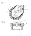
Figs. 5A and 5B show the stacking and inserting of the plurality of the plate-like workpieces shown inFigs. 1A and 1B in the cylindrical member shown inFigs. 2A and 2B ; -
Figs. 6A and 6B show the holding of the upper end and lower end of the plate-like workpieces stacked and inserted in the cylindrical member shown inFigs. 2A and 2B using the lid members shown inFigs. 3A to 3C ; -
Figs. 7A and 7B show the mounting of the cylindrical member that holds the plurality of workpieces as shown inFigs. 6A and 6B and the upper and lower lid members on the workpiece stage mount member shown inFigs. 4A and 4B ; and -
Figs. 8A and 8B show the machining of the plurality of plate-like workpieces held by the cylindrical member attached to the workpiece stage mount member as shown inFigs. 7A and 7B and the upper and lower lid members using a wire electric discharge machine. - First, a plate-like workpiece holder according to an embodiment of the present invention will be described with reference to
Figs. 1A to 4B . -
Figs. 1A and 1B show an example of one plate-like workpiece. A plate-like workpiece 2 is a substantially rectangular thin-plate with ahole 3 at the center thereof as shown in the plan view inFig. 1A and upper, and lower surfaces of which are parallel to each other as shown inFig. 1B . - The workpiece holder for holding a plurality of the plate-like workpieces shown in
Figs. 1A (plan view) and 1B (side view) includes a cylindrical member 10 (seeFigs. 2A and 2B ), upper and lower lid members 20 (seeFigs. 3A to 3C ), and a workpiece stage mount member 30 (seeFigs. 4A and 4B ). This workpiece holder is used for wire electric discharge machines. - First, an example of the
cylindrical member 10 included in the workpiece holder will be described with reference toFigs. 2A and 2B. Fig. 2A is a top view andFig. 2B is a cross-sectional view taken along a dashedline 18. - The
cylindrical member 10 includes a throughhole 11 in which the plurality of plate-like workpieces 2 are inserted and housed, aflange 14 for supporting thecylindrical member 10 via the workpiece stage mount member 30 (described later), bolt holes 15 into which securing bolts 5 (seeFig. 8A ) are inserted, bolt holes 17 into which securing bolts 7 (seeFig. 8A ) are inserted, and aninsertion section 16, which is inserted into aninsertion hole 31 of the workpiecestage mount member 30.Concave sections hole 11. - Next, an example of the
lid members 20 included in the workpiece holder will be described with reference toFigs. 3A to 3C. Fig. 3A is a top view of thelid member 20,Fig. 3B is a side view of thelid member 20 secured to the upper surface of thecylindrical member 10 with the securingbolts 5, andFig. 3C is a side view of thelid member 20 secured to the lower surface of thecylindrical member 10 with the securingbolts 5. - The
lid members 20 are placed on the upper end and lower end of thecylindrical member 10 in which the plurality of plate-like workpieces 2 are housed so as to press the upper end and the lower end of the plate-like workpieces 2. Thelid member 20 mounted on the upper surface of thecylindrical member 10 includes amember 20a and amember 20b, which are symmetrical. Similarly, thelid member 20 mounted on the lower surface of thecylindrical member 10 includes amember 20c and amember 20d, which are symmetrical. In this embodiment, thesemembers lid members 20 have the same shape, and boltholes 21 that correspond to the bolt holes 15 disposed in thecylindrical member 10 are provided in themembers Fig. 8A ) into the bolt holes 15 and the bolt holes 21 can secure theupper lid member 20 and thelower lid member 20 to the upper surface and the lower surface of thecylindrical member 10, respectively. - This causes the
cylindrical member 10 to prevent the plurality of plate-like workpieces 2 from moving in the anteroposterior direction or in the horizontal direction and causes the upper andlower lid members 20 to prevent the plurality of plate-like workpieces 2 from moving in the vertical direction. In addition, the plate-like workpieces 2 may be held by providing a projection or an elastic member on surfaces of thecylindrical member 10 and thelid members 20 that face the plate-like workpieces 2. The projection or elastic member to be provided may be detachable. - Next, an example of the workpiece stage mount member included in the workpiece holder will be described with reference to
Figs. 4A and 4B. Fig. 4A is a top view as viewed from above andFig. 4B is a cross-sectional view of the workpiece stage mount member ofFig. 4A . - The workpiece
stage mount member 30 has theinsertion hole 31 into which theinsertion section 16 of thecylindrical member 10 is inserted, bolt holes 33 into which securingbolts 32 are screwed, and boltholes 34 into which the securingbolts 7 to be screwed into bolt holes 17 formed in theflange 14 of thecylindrical member 10 are screwed. The workpiecestage mount member 30 is secured to aworkpiece stage 40 of the machine body (not shown) of a wire electric discharge machine with the securingbolts 32, as shown inFig. 4B . - Next, stacking and holding of a plurality of plate-
like workpieces 2 shown inFigs. 1A and 1B in the workpiece holder shown inFigs. 2A to 4B and securing of the workpiece holder that holds the plurality of plate-like workpieces 2 to the workpiece stage 40 (seeFig. 4B ) will be described with reference toFigs. 5A to 7B . - As described above, the workpiece holder includes the
cylindrical member 10, the upper andlower lid members 20, and the workpiecestage mount member 30. Thecylindrical member 10 houses a plurality of plate-like workpieces 2 and holds the ends of these plate-like workpieces 2 in their horizontal direction and anteroposterior direction, the upper andlower lid members 20 holds the upper and lower ends of the plurality of plate-like workpieces 2 housed in thecylindrical member 10, and the workpiecestage mount member 30 secures thecylindrical member 10 that has housed the plurality of plate-like workpieces 2 to thelid members 20 placed on the upper and lower ends of the plurality of plate-like workpieces 2. - As shown in
Figs. 5A and 5B , the plurality of plate-like workpieces 2 are stacked and inserted into the throughhole 11 of the cylindrical member 10 (see the arrow inFig. 5B ). In addition, as shown inFigs. 6A and 6B , thelid members 20 are placed on the upper end and the lower end of the plurality of plate-like workpieces 2 housed in the throughhole 11 of thecylindrical member 10 so as to press the upper end and the lower end of the plurality of plate-like workpieces 2 (see the arrows inFig. 6B ). This holds the ends in the horizontal direction, the anteroposterior direction, and vertical direction of the plurality of the plate-like workpieces 2 stacked (see the arrows inFig. 6B ). - Then, as shown in
Figs. 7A and 7B , thecylindrical member 10 in which the plurality of plate-like workpieces 2 are held in a stacked state and thelid members 20 are mounted on the workpiecestage mount member 30 secured to theworkpiece stage 40 of the wire electric discharge machine with the securing bolts 5 (seeFig. 8A ) screwed into the bolt holes 15 of thecylindrical member 10 and the bolt holes 21 of thelid members 20 in a state where the plate-like workpieces 2 is held (see the arrow inFig. 7B ). - Next, how a plurality of plate-
like workpieces 2 held by the workpiece holder (including thecylindrical member 10, the upper andlower lid members 20, and the workpiece stage mount member 30) are machined by a wire electric discharge machine will be described with reference toFigs. 8A and 8B . - After moving the X-axis and Y-axis of the wire electric discharge machine to the concave section 12 (see
Fig. 8A ) formed in a position that corresponds to the machining start point of wire electric discharge machining on the inner circumference surface of the throughhole 11 of thecylindrical member 10 in which a plurality of plate-like workpieces 2 is inserted and housed, wire electric discharge machining is started upon completion of connection of awire electrode 46 passing through anupper nozzle 42 of an upper guide part and alower nozzle 44 of a lower guide part. Since wire electric discharge machining is completed when wire electric discharge machining proceeds and reaches theconcave section 13 formed in a position that corresponds to the machining end point of wire electric discharge machining on the inner circumference surface of the throughhole 11 of thecylindrical member 10, thewire electrode 46 is cut in this position. - The
cylindrical member 10 that holds the plurality of plate-like workpieces 2 for which electric discharge machining was completed and thelid members 20 are removed from the workpiecestage mount member 30. Alternatively, thecylindrical member 10 that holds the plurality of plate-like workpieces 2 and thelid members 20 may be mounted on the workpiecestage mount member 30 secured in advance to a different position on theworkpiece stage 40, and, as in the above case, the X-axis and Y-axis of the wire electric discharge machine may be moved to the concave section 12 (seeFig. 8A ) formed in a position that corresponds to the machining start point of wire electric discharge machining on the inner circumference surface of the throughhole 11 of the mountedcylindrical member 10 in order to perform wire electric discharge machining. - As described above, the workpiece holder of the present invention that holds a plurality of plate-like workpieces, used for electric discharge machines, has the following effects more advantageous than the prior art.
- (1) Since the plate-
like workpieces 2 can be held precisely in close contact with each other if the plate-like workpieces 2 are held in a stacked state, efficient wire electric discharge machining is enabled. - (2) Since the workpiece holder can hold the plurality of plate-
like workpieces 2 housed in thecylindrical member 10 vialid members 20 at the outside of the body of the wire electric discharge machine, it is possible to prepare the workpiece holder for holding the plate-like workpieces 2 regardless of the operation state of the wire electric discharge machine, thereby enabling efficient wire electric discharge machining. - (3) Since the workpiece holder can be secured to the wire electric discharge machine in a state where the plate-
like workpieces 2 are held and wire electric discharge machining can be performed in a state where the plate-like workpieces 2 are held, thereby enabling efficient wire electric discharge machining. - (4) Since the plate-
like workpieces 2 make closely contact with theupper nozzle 42 and thelower nozzle 44 of the wire electric discharge machine when thecylindrical member 10 that housed the plate-like workpieces 2 and thelid members 20 are mounted on the workpiecestage mount member 30 of the wire electric discharge machine, machining fluid from theupper nozzle 42 and thelower nozzle 44 can be efficiently supplied to a part undergoing electric discharge during wire electric discharge machining, thereby enabling efficient wire electric discharge machining. - (5) Since the
concave sections cylindrical member 10, wire electric discharge machining is not blocked when the workpieces are held via thelid members 20, thereby enabling efficient wire electric discharge machining. - (6) Since the
concave sections cylindrical member 10 having housed the plurality of plate-like workpieces 2 and thelid members 20 on the workpiecestage mount member 30, wire electric discharge machining is not blocked, thereby enabling efficient wire electric discharge machining. - (7) Since the workpiece holder holds the plate-
like workpieces 2 to prevent movement in the horizontal direction (X-axis direction) and the anteroposterior direction (Y-axis direction) in addition to the vertical direction (Z-axis direction), the plate-like workpieces 2 can be secured with little deviation and space between the stacked workpieces.
Claims (4)
- A plate-like workpiece holder for holding a plurality of plate-like workpieces used for a wire electric discharge machine, in which the wire electric discharge machine relatively moves a wire electrode stretched between upper and lower wire guides with respect to the plurality of plate-like workpieces stacked on a workpiece stage so as to machine the plurality of plate-like workpieces stacked, the workpiece holder for holding the plurality of plate-like workpieces stacked comprising:a cylindrical member in which the plurality of plate-like workpieces are held in a stacked state and which has an inner circumference surface where concave sections corresponding to a machining start point and a machining end point are provided;lid members that are mounted on an upper end and a lower end of the cylindrical member to press the plurality of plate-like workpieces; anda workpiece stage mount member which is secured to the workpiece stage and which has an insertion hole in which the cylindrical member is inserted and housed.
- The plate-like workpiece holder for holding a plurality of plate-like workpieces used for a wire electric discharge machine according to claim 1, wherein a projection or an elastic member that holds the plurality of plate-like workpieces is provided in a predetermined position on the inner circumference surface of the cylindrical member.
- The plate-like workpiece holder for holding a plurality of plate-like workpieces used for a wire electric discharge machine according to claim 1 or 2, wherein a projection or an elastic member that holds the plurality of plate-like workpieces is provided on surfaces of the lid members that face the plurality of plate-like workpieces.
- The plate-like workpiece holder for holding a plurality of plate-like workpieces used for a wire electric discharge machine according to any one of claims 1 to 3, wherein each of the lid members is divided according to a machining path of the plurality of plate-like workpieces.
Applications Claiming Priority (1)
| Application Number | Priority Date | Filing Date | Title |
|---|---|---|---|
| JP2012096820A JP5369215B2 (en) | 2012-04-20 | 2012-04-20 | Holder for multiple plate workpieces used in wire electric discharge machines |
Publications (3)
| Publication Number | Publication Date |
|---|---|
| EP2653254A2 true EP2653254A2 (en) | 2013-10-23 |
| EP2653254A3 EP2653254A3 (en) | 2014-11-12 |
| EP2653254B1 EP2653254B1 (en) | 2017-03-22 |
Family
ID=47779929
Family Applications (1)
| Application Number | Title | Priority Date | Filing Date |
|---|---|---|---|
| EP13157283.6A Active EP2653254B1 (en) | 2012-04-20 | 2013-02-28 | Workpiece holder for holding a plurality of plate-like workpieces used for wire electric discharge machine |
Country Status (4)
| Country | Link |
|---|---|
| US (1) | US8975552B2 (en) |
| EP (1) | EP2653254B1 (en) |
| JP (1) | JP5369215B2 (en) |
| CN (1) | CN203316863U (en) |
Cited By (4)
| Publication number | Priority date | Publication date | Assignee | Title |
|---|---|---|---|---|
| EP3072623A1 (en) * | 2015-03-23 | 2016-09-28 | Fanuc Corporation | Workpiece fixing jig used in wire electric discharge machine |
| CN108723522A (en) * | 2018-06-25 | 2018-11-02 | 浙江芊荷科技有限公司 | A kind of spark-erosion machine tool manufactures process equipment and its manufacture processing method automatically |
| CN113634833A (en) * | 2021-08-20 | 2021-11-12 | 江西昌河航空工业有限公司 | A high-precision non-integral surface of revolution processing device and using method |
| CN117399730A (en) * | 2023-10-17 | 2024-01-16 | 新乡航空工业(集团)有限公司 | A wire cutting method and device for heat dissipation bamboo tubes |
Families Citing this family (10)
| Publication number | Priority date | Publication date | Assignee | Title |
|---|---|---|---|---|
| US20150314403A1 (en) * | 2014-05-01 | 2015-11-05 | Siemens Energy, Inc. | Arrangement for laser processing of turbine component |
| CN104816058B (en) * | 2015-04-28 | 2018-01-23 | 力帆实业(集团)股份有限公司 | Motorcycle gear-shifting wheel wire cutting tool structure |
| CN105108381A (en) * | 2015-08-31 | 2015-12-02 | 北京无线电测量研究所 | Manufacturing method for metal-based foil-like brazing filler metal in complex shape |
| CN109822171B (en) * | 2016-08-31 | 2020-10-23 | 郑州磨料磨具磨削研究所有限公司 | Electric spark wire cutting clamp |
| BE1025016B1 (en) * | 2017-03-02 | 2018-10-03 | Safran Aero Boosters S.A. | MACHINE AND METHOD FOR ELECTROEROSION MACHINING OF GEROTOR PUMP |
| JP6291619B1 (en) * | 2017-07-20 | 2018-03-14 | 西部電機株式会社 | Wire electric discharge machining system and wire electric discharge machining method |
| CN108406021B (en) * | 2018-04-03 | 2019-06-11 | 航天精工股份有限公司 | A kind of inside and outside toothing processing unit (plant) of tooth form bushing |
| US12194557B2 (en) * | 2019-07-19 | 2025-01-14 | The Boeing Company | Fixture that holds a specimen during electrical discharge machining of the specimen |
| CN112975019B (en) * | 2021-02-07 | 2022-04-22 | 深圳市星欣磊实业有限公司 | Wire cutting tool for processing single-fiber bidirectional optical transceiver module component |
| CN113634838A (en) * | 2021-07-28 | 2021-11-12 | 上海实达精密不锈钢有限公司 | A kind of stainless steel strip wire cutting tool and using method |
Citations (1)
| Publication number | Priority date | Publication date | Assignee | Title |
|---|---|---|---|---|
| JPH0647625A (en) | 1992-07-28 | 1994-02-22 | Kurosaki Rokogyo Kk | Stack-cutting method for metallic foil and its locking device for stack cutting |
Family Cites Families (9)
| Publication number | Priority date | Publication date | Assignee | Title |
|---|---|---|---|---|
| JPS61260937A (en) * | 1985-05-16 | 1986-11-19 | Japax Inc | Method of fabricating functional component part |
| JPS62157723A (en) * | 1985-09-06 | 1987-07-13 | Hirotake Morita | Workpiece fixing device for wire-cut electric discharge machine |
| CH668331A5 (en) * | 1985-11-11 | 1988-12-15 | Studer Willi Ag | Magnetic head core mfr. from stack of laminations - involves linear machining of patterns from adhesively bonded and rolled sandwich of permeable and non-permeable layers |
| US5019129A (en) * | 1990-07-18 | 1991-05-28 | Lars Johanson | Workpiece holding system |
| US5981895A (en) * | 1997-06-03 | 1999-11-09 | Grace Manufacturing Inc. | Method of manufacture of a bone saw blade by wire cutting electric discharge machining |
| JP2003220427A (en) * | 2002-01-25 | 2003-08-05 | Seiko Epson Corp | Mold plate simultaneous processing method and mold plate |
| JP4434158B2 (en) * | 2006-02-17 | 2010-03-17 | 株式会社デンソー | Electric discharge machining method and electric discharge machining apparatus used therefor |
| IL180639A0 (en) * | 2006-03-13 | 2007-06-03 | Tool Internat Ag F | Clamping apparatus for positioning and fixing work pieces |
| JP5096717B2 (en) * | 2006-09-26 | 2012-12-12 | パナソニック株式会社 | Work fixture and work machining method |
-
2012
- 2012-04-20 JP JP2012096820A patent/JP5369215B2/en not_active Expired - Fee Related
-
2013
- 2013-02-28 EP EP13157283.6A patent/EP2653254B1/en active Active
- 2013-03-08 US US13/791,037 patent/US8975552B2/en active Active
- 2013-04-22 CN CN2013202061227U patent/CN203316863U/en not_active Expired - Lifetime
Patent Citations (1)
| Publication number | Priority date | Publication date | Assignee | Title |
|---|---|---|---|---|
| JPH0647625A (en) | 1992-07-28 | 1994-02-22 | Kurosaki Rokogyo Kk | Stack-cutting method for metallic foil and its locking device for stack cutting |
Cited By (4)
| Publication number | Priority date | Publication date | Assignee | Title |
|---|---|---|---|---|
| EP3072623A1 (en) * | 2015-03-23 | 2016-09-28 | Fanuc Corporation | Workpiece fixing jig used in wire electric discharge machine |
| CN108723522A (en) * | 2018-06-25 | 2018-11-02 | 浙江芊荷科技有限公司 | A kind of spark-erosion machine tool manufactures process equipment and its manufacture processing method automatically |
| CN113634833A (en) * | 2021-08-20 | 2021-11-12 | 江西昌河航空工业有限公司 | A high-precision non-integral surface of revolution processing device and using method |
| CN117399730A (en) * | 2023-10-17 | 2024-01-16 | 新乡航空工业(集团)有限公司 | A wire cutting method and device for heat dissipation bamboo tubes |
Also Published As
| Publication number | Publication date |
|---|---|
| EP2653254A3 (en) | 2014-11-12 |
| CN203316863U (en) | 2013-12-04 |
| JP2013223900A (en) | 2013-10-31 |
| JP5369215B2 (en) | 2013-12-18 |
| EP2653254B1 (en) | 2017-03-22 |
| US8975552B2 (en) | 2015-03-10 |
| US20130277347A1 (en) | 2013-10-24 |
Similar Documents
| Publication | Publication Date | Title |
|---|---|---|
| EP2653254B1 (en) | Workpiece holder for holding a plurality of plate-like workpieces used for wire electric discharge machine | |
| US8800128B2 (en) | Workpiece clamping jig and workpiece machining method using workpiece clamping jig | |
| US10298103B2 (en) | Manufacturing method of laminated core and manufacturing device of laminated core | |
| JP2015530275A (en) | Method for setting punching gap and tool unit | |
| US10556310B2 (en) | Method for cutting machining of turbine blades | |
| CN106826331A (en) | Positioning clamp | |
| EP3072623A1 (en) | Workpiece fixing jig used in wire electric discharge machine | |
| US20170043439A1 (en) | Vibration suppression method for suppressing vibration of object to be processed, and machine processing system | |
| KR101843254B1 (en) | Electrical discharge machine | |
| US20120312064A1 (en) | Punching Sheet Metal | |
| JP6282773B1 (en) | Masking jig, electroplating equipment | |
| JP6604438B2 (en) | Cutting tool support device and machine tool | |
| JP2019536637A (en) | Manufacturing equipment with clamping tool and method for adapting the overall length of the bending edge of the clamping tool | |
| JP2007000985A (en) | Jig, workpiece manufacturing method and sewing head manufacturing method | |
| JP2019162693A (en) | Punching method and metal die | |
| JP2015022839A (en) | Fixing jig and assembled battery assembling method using the same | |
| CN203579222U (en) | Positioning device | |
| KR101453394B1 (en) | Apparatus of coil cutting and grinding jig sets | |
| JP2015039706A (en) | Mold for punch press, punch press device and processing method | |
| CN210099844U (en) | Special fixture for machining center of large electric hammer electric tool | |
| JP2015098078A (en) | Rod-like or platy workpiece-holding tool in wire electric discharge machine | |
| US20160059396A1 (en) | Device for assembling a fuel injector assembly | |
| CN211276874U (en) | Electronic product soldering tin anchor clamps and soldering tin machine | |
| CN104325319A (en) | Base for shell fixture | |
| CN213225212U (en) | Auxiliary fixing tool for machining side plates of machine head of belt conveyor |
Legal Events
| Date | Code | Title | Description |
|---|---|---|---|
| PUAI | Public reference made under article 153(3) epc to a published international application that has entered the european phase |
Free format text: ORIGINAL CODE: 0009012 |
|
| AK | Designated contracting states |
Kind code of ref document: A2 Designated state(s): AL AT BE BG CH CY CZ DE DK EE ES FI FR GB GR HR HU IE IS IT LI LT LU LV MC MK MT NL NO PL PT RO RS SE SI SK SM TR |
|
| AX | Request for extension of the european patent |
Extension state: BA ME |
|
| PUAL | Search report despatched |
Free format text: ORIGINAL CODE: 0009013 |
|
| AK | Designated contracting states |
Kind code of ref document: A3 Designated state(s): AL AT BE BG CH CY CZ DE DK EE ES FI FR GB GR HR HU IE IS IT LI LT LU LV MC MK MT NL NO PL PT RO RS SE SI SK SM TR |
|
| AX | Request for extension of the european patent |
Extension state: BA ME |
|
| RIC1 | Information provided on ipc code assigned before grant |
Ipc: B23H 11/00 20060101AFI20141006BHEP Ipc: B23H 7/02 20060101ALN20141006BHEP |
|
| 17P | Request for examination filed |
Effective date: 20150506 |
|
| RBV | Designated contracting states (corrected) |
Designated state(s): AL AT BE BG CH CY CZ DE DK EE ES FI FR GB GR HR HU IE IS IT LI LT LU LV MC MK MT NL NO PL PT RO RS SE SI SK SM TR |
|
| GRAP | Despatch of communication of intention to grant a patent |
Free format text: ORIGINAL CODE: EPIDOSNIGR1 |
|
| RIC1 | Information provided on ipc code assigned before grant |
Ipc: B23H 11/00 20060101AFI20161012BHEP Ipc: B23H 7/02 20060101ALN20161012BHEP |
|
| INTG | Intention to grant announced |
Effective date: 20161104 |
|
| RIC1 | Information provided on ipc code assigned before grant |
Ipc: B23H 7/02 20060101ALN20161024BHEP Ipc: B23H 11/00 20060101AFI20161024BHEP |
|
| GRAS | Grant fee paid |
Free format text: ORIGINAL CODE: EPIDOSNIGR3 |
|
| GRAA | (expected) grant |
Free format text: ORIGINAL CODE: 0009210 |
|
| AK | Designated contracting states |
Kind code of ref document: B1 Designated state(s): AL AT BE BG CH CY CZ DE DK EE ES FI FR GB GR HR HU IE IS IT LI LT LU LV MC MK MT NL NO PL PT RO RS SE SI SK SM TR |
|
| REG | Reference to a national code |
Ref country code: GB Ref legal event code: FG4D |
|
| REG | Reference to a national code |
Ref country code: CH Ref legal event code: EP Ref country code: CH Ref legal event code: NV Representative=s name: DR. LUSUARDI AG, CH |
|
| REG | Reference to a national code |
Ref country code: AT Ref legal event code: REF Ref document number: 877223 Country of ref document: AT Kind code of ref document: T Effective date: 20170415 |
|
| REG | Reference to a national code |
Ref country code: IE Ref legal event code: FG4D |
|
| REG | Reference to a national code |
Ref country code: DE Ref legal event code: R096 Ref document number: 602013018782 Country of ref document: DE |
|
| REG | Reference to a national code |
Ref country code: NL Ref legal event code: MP Effective date: 20170322 |
|
| PG25 | Lapsed in a contracting state [announced via postgrant information from national office to epo] |
Ref country code: NO Free format text: LAPSE BECAUSE OF FAILURE TO SUBMIT A TRANSLATION OF THE DESCRIPTION OR TO PAY THE FEE WITHIN THE PRESCRIBED TIME-LIMIT Effective date: 20170622 Ref country code: GR Free format text: LAPSE BECAUSE OF FAILURE TO SUBMIT A TRANSLATION OF THE DESCRIPTION OR TO PAY THE FEE WITHIN THE PRESCRIBED TIME-LIMIT Effective date: 20170623 Ref country code: HR Free format text: LAPSE BECAUSE OF FAILURE TO SUBMIT A TRANSLATION OF THE DESCRIPTION OR TO PAY THE FEE WITHIN THE PRESCRIBED TIME-LIMIT Effective date: 20170322 Ref country code: FI Free format text: LAPSE BECAUSE OF FAILURE TO SUBMIT A TRANSLATION OF THE DESCRIPTION OR TO PAY THE FEE WITHIN THE PRESCRIBED TIME-LIMIT Effective date: 20170322 Ref country code: LT Free format text: LAPSE BECAUSE OF FAILURE TO SUBMIT A TRANSLATION OF THE DESCRIPTION OR TO PAY THE FEE WITHIN THE PRESCRIBED TIME-LIMIT Effective date: 20170322 |
|
| REG | Reference to a national code |
Ref country code: LT Ref legal event code: MG4D |
|
| REG | Reference to a national code |
Ref country code: AT Ref legal event code: MK05 Ref document number: 877223 Country of ref document: AT Kind code of ref document: T Effective date: 20170322 |
|
| PG25 | Lapsed in a contracting state [announced via postgrant information from national office to epo] |
Ref country code: SE Free format text: LAPSE BECAUSE OF FAILURE TO SUBMIT A TRANSLATION OF THE DESCRIPTION OR TO PAY THE FEE WITHIN THE PRESCRIBED TIME-LIMIT Effective date: 20170322 Ref country code: LV Free format text: LAPSE BECAUSE OF FAILURE TO SUBMIT A TRANSLATION OF THE DESCRIPTION OR TO PAY THE FEE WITHIN THE PRESCRIBED TIME-LIMIT Effective date: 20170322 Ref country code: RS Free format text: LAPSE BECAUSE OF FAILURE TO SUBMIT A TRANSLATION OF THE DESCRIPTION OR TO PAY THE FEE WITHIN THE PRESCRIBED TIME-LIMIT Effective date: 20170322 Ref country code: BG Free format text: LAPSE BECAUSE OF FAILURE TO SUBMIT A TRANSLATION OF THE DESCRIPTION OR TO PAY THE FEE WITHIN THE PRESCRIBED TIME-LIMIT Effective date: 20170622 |
|
| PG25 | Lapsed in a contracting state [announced via postgrant information from national office to epo] |
Ref country code: NL Free format text: LAPSE BECAUSE OF FAILURE TO SUBMIT A TRANSLATION OF THE DESCRIPTION OR TO PAY THE FEE WITHIN THE PRESCRIBED TIME-LIMIT Effective date: 20170322 |
|
| PG25 | Lapsed in a contracting state [announced via postgrant information from national office to epo] |
Ref country code: AT Free format text: LAPSE BECAUSE OF FAILURE TO SUBMIT A TRANSLATION OF THE DESCRIPTION OR TO PAY THE FEE WITHIN THE PRESCRIBED TIME-LIMIT Effective date: 20170322 Ref country code: SK Free format text: LAPSE BECAUSE OF FAILURE TO SUBMIT A TRANSLATION OF THE DESCRIPTION OR TO PAY THE FEE WITHIN THE PRESCRIBED TIME-LIMIT Effective date: 20170322 Ref country code: RO Free format text: LAPSE BECAUSE OF FAILURE TO SUBMIT A TRANSLATION OF THE DESCRIPTION OR TO PAY THE FEE WITHIN THE PRESCRIBED TIME-LIMIT Effective date: 20170322 Ref country code: ES Free format text: LAPSE BECAUSE OF FAILURE TO SUBMIT A TRANSLATION OF THE DESCRIPTION OR TO PAY THE FEE WITHIN THE PRESCRIBED TIME-LIMIT Effective date: 20170322 Ref country code: EE Free format text: LAPSE BECAUSE OF FAILURE TO SUBMIT A TRANSLATION OF THE DESCRIPTION OR TO PAY THE FEE WITHIN THE PRESCRIBED TIME-LIMIT Effective date: 20170322 Ref country code: CZ Free format text: LAPSE BECAUSE OF FAILURE TO SUBMIT A TRANSLATION OF THE DESCRIPTION OR TO PAY THE FEE WITHIN THE PRESCRIBED TIME-LIMIT Effective date: 20170322 |
|
| PG25 | Lapsed in a contracting state [announced via postgrant information from national office to epo] |
Ref country code: PT Free format text: LAPSE BECAUSE OF FAILURE TO SUBMIT A TRANSLATION OF THE DESCRIPTION OR TO PAY THE FEE WITHIN THE PRESCRIBED TIME-LIMIT Effective date: 20170724 Ref country code: IS Free format text: LAPSE BECAUSE OF FAILURE TO SUBMIT A TRANSLATION OF THE DESCRIPTION OR TO PAY THE FEE WITHIN THE PRESCRIBED TIME-LIMIT Effective date: 20170722 Ref country code: SM Free format text: LAPSE BECAUSE OF FAILURE TO SUBMIT A TRANSLATION OF THE DESCRIPTION OR TO PAY THE FEE WITHIN THE PRESCRIBED TIME-LIMIT Effective date: 20170322 Ref country code: PL Free format text: LAPSE BECAUSE OF FAILURE TO SUBMIT A TRANSLATION OF THE DESCRIPTION OR TO PAY THE FEE WITHIN THE PRESCRIBED TIME-LIMIT Effective date: 20170322 |
|
| REG | Reference to a national code |
Ref country code: DE Ref legal event code: R097 Ref document number: 602013018782 Country of ref document: DE |
|
| PLBE | No opposition filed within time limit |
Free format text: ORIGINAL CODE: 0009261 |
|
| STAA | Information on the status of an ep patent application or granted ep patent |
Free format text: STATUS: NO OPPOSITION FILED WITHIN TIME LIMIT |
|
| PG25 | Lapsed in a contracting state [announced via postgrant information from national office to epo] |
Ref country code: DK Free format text: LAPSE BECAUSE OF FAILURE TO SUBMIT A TRANSLATION OF THE DESCRIPTION OR TO PAY THE FEE WITHIN THE PRESCRIBED TIME-LIMIT Effective date: 20170322 |
|
| 26N | No opposition filed |
Effective date: 20180102 |
|
| PG25 | Lapsed in a contracting state [announced via postgrant information from national office to epo] |
Ref country code: SI Free format text: LAPSE BECAUSE OF FAILURE TO SUBMIT A TRANSLATION OF THE DESCRIPTION OR TO PAY THE FEE WITHIN THE PRESCRIBED TIME-LIMIT Effective date: 20170322 Ref country code: IT Free format text: LAPSE BECAUSE OF FAILURE TO SUBMIT A TRANSLATION OF THE DESCRIPTION OR TO PAY THE FEE WITHIN THE PRESCRIBED TIME-LIMIT Effective date: 20170322 |
|
| PG25 | Lapsed in a contracting state [announced via postgrant information from national office to epo] |
Ref country code: MC Free format text: LAPSE BECAUSE OF FAILURE TO SUBMIT A TRANSLATION OF THE DESCRIPTION OR TO PAY THE FEE WITHIN THE PRESCRIBED TIME-LIMIT Effective date: 20170322 |
|
| GBPC | Gb: european patent ceased through non-payment of renewal fee |
Effective date: 20180228 |
|
| REG | Reference to a national code |
Ref country code: IE Ref legal event code: MM4A |
|
| REG | Reference to a national code |
Ref country code: BE Ref legal event code: MM Effective date: 20180228 |
|
| PG25 | Lapsed in a contracting state [announced via postgrant information from national office to epo] |
Ref country code: LU Free format text: LAPSE BECAUSE OF NON-PAYMENT OF DUE FEES Effective date: 20180228 |
|
| REG | Reference to a national code |
Ref country code: FR Ref legal event code: ST Effective date: 20181031 |
|
| PG25 | Lapsed in a contracting state [announced via postgrant information from national office to epo] |
Ref country code: IE Free format text: LAPSE BECAUSE OF NON-PAYMENT OF DUE FEES Effective date: 20180228 |
|
| PG25 | Lapsed in a contracting state [announced via postgrant information from national office to epo] |
Ref country code: FR Free format text: LAPSE BECAUSE OF NON-PAYMENT OF DUE FEES Effective date: 20180228 Ref country code: BE Free format text: LAPSE BECAUSE OF NON-PAYMENT OF DUE FEES Effective date: 20180228 Ref country code: GB Free format text: LAPSE BECAUSE OF NON-PAYMENT OF DUE FEES Effective date: 20180228 |
|
| PG25 | Lapsed in a contracting state [announced via postgrant information from national office to epo] |
Ref country code: MT Free format text: LAPSE BECAUSE OF NON-PAYMENT OF DUE FEES Effective date: 20180228 |
|
| PG25 | Lapsed in a contracting state [announced via postgrant information from national office to epo] |
Ref country code: TR Free format text: LAPSE BECAUSE OF FAILURE TO SUBMIT A TRANSLATION OF THE DESCRIPTION OR TO PAY THE FEE WITHIN THE PRESCRIBED TIME-LIMIT Effective date: 20170322 |
|
| PG25 | Lapsed in a contracting state [announced via postgrant information from national office to epo] |
Ref country code: HU Free format text: LAPSE BECAUSE OF FAILURE TO SUBMIT A TRANSLATION OF THE DESCRIPTION OR TO PAY THE FEE WITHIN THE PRESCRIBED TIME-LIMIT; INVALID AB INITIO Effective date: 20130228 |
|
| PG25 | Lapsed in a contracting state [announced via postgrant information from national office to epo] |
Ref country code: MK Free format text: LAPSE BECAUSE OF NON-PAYMENT OF DUE FEES Effective date: 20170322 Ref country code: CY Free format text: LAPSE BECAUSE OF FAILURE TO SUBMIT A TRANSLATION OF THE DESCRIPTION OR TO PAY THE FEE WITHIN THE PRESCRIBED TIME-LIMIT Effective date: 20170322 |
|
| PG25 | Lapsed in a contracting state [announced via postgrant information from national office to epo] |
Ref country code: AL Free format text: LAPSE BECAUSE OF FAILURE TO SUBMIT A TRANSLATION OF THE DESCRIPTION OR TO PAY THE FEE WITHIN THE PRESCRIBED TIME-LIMIT Effective date: 20170322 |
|
| REG | Reference to a national code |
Ref country code: DE Ref legal event code: R082 Ref document number: 602013018782 Country of ref document: DE Representative=s name: HL KEMPNER PATENTANWAELTE, SOLICITORS (ENGLAND, DE Ref country code: DE Ref legal event code: R082 Ref document number: 602013018782 Country of ref document: DE Representative=s name: HL KEMPNER PATENTANWALT, RECHTSANWALT, SOLICIT, DE Ref country code: DE Ref legal event code: R082 Ref document number: 602013018782 Country of ref document: DE Representative=s name: HL KEMPNER PARTG MBB, DE |
|
| PGFP | Annual fee paid to national office [announced via postgrant information from national office to epo] |
Ref country code: DE Payment date: 20231229 Year of fee payment: 12 Ref country code: CH Payment date: 20240301 Year of fee payment: 12 |
|
| REG | Reference to a national code |
Ref country code: DE Ref legal event code: R119 Ref document number: 602013018782 Country of ref document: DE |
|
| REG | Reference to a national code |
Ref country code: CH Ref legal event code: PL |
|
| PG25 | Lapsed in a contracting state [announced via postgrant information from national office to epo] |
Ref country code: CH Free format text: LAPSE BECAUSE OF NON-PAYMENT OF DUE FEES Effective date: 20250228 |
|
| PG25 | Lapsed in a contracting state [announced via postgrant information from national office to epo] |
Ref country code: DE Free format text: LAPSE BECAUSE OF NON-PAYMENT OF DUE FEES Effective date: 20250902 |