EP2653099A1 - Lancet device capable of lancet detachment - Google Patents
Lancet device capable of lancet detachment Download PDFInfo
- Publication number
- EP2653099A1 EP2653099A1 EP11848367.6A EP11848367A EP2653099A1 EP 2653099 A1 EP2653099 A1 EP 2653099A1 EP 11848367 A EP11848367 A EP 11848367A EP 2653099 A1 EP2653099 A1 EP 2653099A1
- Authority
- EP
- European Patent Office
- Prior art keywords
- lancet
- holder
- separation
- bar
- hole
- Prior art date
- Legal status (The legal status is an assumption and is not a legal conclusion. Google has not performed a legal analysis and makes no representation as to the accuracy of the status listed.)
- Granted
Links
Images


Classifications
-
- A—HUMAN NECESSITIES
- A61—MEDICAL OR VETERINARY SCIENCE; HYGIENE
- A61B—DIAGNOSIS; SURGERY; IDENTIFICATION
- A61B5/00—Measuring for diagnostic purposes; Identification of persons
- A61B5/15—Devices for taking samples of blood
- A61B5/151—Devices specially adapted for taking samples of capillary blood, e.g. by lancets, needles or blades
- A61B5/15101—Details
-
- A—HUMAN NECESSITIES
- A61—MEDICAL OR VETERINARY SCIENCE; HYGIENE
- A61B—DIAGNOSIS; SURGERY; IDENTIFICATION
- A61B5/00—Measuring for diagnostic purposes; Identification of persons
- A61B5/15—Devices for taking samples of blood
- A61B5/151—Devices specially adapted for taking samples of capillary blood, e.g. by lancets, needles or blades
- A61B5/15101—Details
- A61B5/15103—Piercing procedure
- A61B5/15107—Piercing being assisted by a triggering mechanism
- A61B5/15113—Manually triggered, i.e. the triggering requires a deliberate action by the user such as pressing a drive button
-
- A—HUMAN NECESSITIES
- A61—MEDICAL OR VETERINARY SCIENCE; HYGIENE
- A61B—DIAGNOSIS; SURGERY; IDENTIFICATION
- A61B5/00—Measuring for diagnostic purposes; Identification of persons
- A61B5/15—Devices for taking samples of blood
- A61B5/151—Devices specially adapted for taking samples of capillary blood, e.g. by lancets, needles or blades
- A61B5/15101—Details
- A61B5/15115—Driving means for propelling the piercing element to pierce the skin, e.g. comprising mechanisms based on shape memory alloys, magnetism, solenoids, piezoelectric effect, biased elements, resilient elements, vacuum or compressed fluids
- A61B5/15117—Driving means for propelling the piercing element to pierce the skin, e.g. comprising mechanisms based on shape memory alloys, magnetism, solenoids, piezoelectric effect, biased elements, resilient elements, vacuum or compressed fluids comprising biased elements, resilient elements or a spring, e.g. a helical spring, leaf spring, or elastic strap
-
- A—HUMAN NECESSITIES
- A61—MEDICAL OR VETERINARY SCIENCE; HYGIENE
- A61B—DIAGNOSIS; SURGERY; IDENTIFICATION
- A61B5/00—Measuring for diagnostic purposes; Identification of persons
- A61B5/15—Devices for taking samples of blood
- A61B5/151—Devices specially adapted for taking samples of capillary blood, e.g. by lancets, needles or blades
- A61B5/15186—Devices loaded with a single lancet, i.e. a single lancet with or without a casing is loaded into a reusable drive device and then discarded after use; drive devices reloadable for multiple use
- A61B5/15188—Constructional features of reusable driving devices
- A61B5/1519—Constructional features of reusable driving devices comprising driving means, e.g. a spring, for propelling the piercing unit
-
- A—HUMAN NECESSITIES
- A61—MEDICAL OR VETERINARY SCIENCE; HYGIENE
- A61B—DIAGNOSIS; SURGERY; IDENTIFICATION
- A61B5/00—Measuring for diagnostic purposes; Identification of persons
- A61B5/15—Devices for taking samples of blood
- A61B5/150007—Details
- A61B5/150015—Source of blood
- A61B5/150022—Source of blood for capillary blood or interstitial fluid
-
- A—HUMAN NECESSITIES
- A61—MEDICAL OR VETERINARY SCIENCE; HYGIENE
- A61B—DIAGNOSIS; SURGERY; IDENTIFICATION
- A61B5/00—Measuring for diagnostic purposes; Identification of persons
- A61B5/15—Devices for taking samples of blood
- A61B5/150007—Details
- A61B5/150053—Details for enhanced collection of blood or interstitial fluid at the sample site, e.g. by applying compression, heat, vibration, ultrasound, suction or vacuum to tissue; for reduction of pain or discomfort; Skin piercing elements, e.g. blades, needles, lancets or canulas, with adjustable piercing speed
- A61B5/150061—Means for enhancing collection
- A61B5/150068—Means for enhancing collection by tissue compression, e.g. with specially designed surface of device contacting the skin area to be pierced
-
- A—HUMAN NECESSITIES
- A61—MEDICAL OR VETERINARY SCIENCE; HYGIENE
- A61B—DIAGNOSIS; SURGERY; IDENTIFICATION
- A61B5/00—Measuring for diagnostic purposes; Identification of persons
- A61B5/15—Devices for taking samples of blood
- A61B5/150007—Details
- A61B5/150053—Details for enhanced collection of blood or interstitial fluid at the sample site, e.g. by applying compression, heat, vibration, ultrasound, suction or vacuum to tissue; for reduction of pain or discomfort; Skin piercing elements, e.g. blades, needles, lancets or canulas, with adjustable piercing speed
- A61B5/150106—Means for reducing pain or discomfort applied before puncturing; desensitising the skin at the location where body is to be pierced
- A61B5/150114—Means for reducing pain or discomfort applied before puncturing; desensitising the skin at the location where body is to be pierced by tissue compression, e.g. with specially designed surface of device contacting the skin area to be pierced
-
- A—HUMAN NECESSITIES
- A61—MEDICAL OR VETERINARY SCIENCE; HYGIENE
- A61B—DIAGNOSIS; SURGERY; IDENTIFICATION
- A61B5/00—Measuring for diagnostic purposes; Identification of persons
- A61B5/15—Devices for taking samples of blood
- A61B5/150007—Details
- A61B5/150374—Details of piercing elements or protective means for preventing accidental injuries by such piercing elements
- A61B5/150381—Design of piercing elements
- A61B5/150412—Pointed piercing elements, e.g. needles, lancets for piercing the skin
-
- A—HUMAN NECESSITIES
- A61—MEDICAL OR VETERINARY SCIENCE; HYGIENE
- A61B—DIAGNOSIS; SURGERY; IDENTIFICATION
- A61B5/00—Measuring for diagnostic purposes; Identification of persons
- A61B5/15—Devices for taking samples of blood
- A61B5/150007—Details
- A61B5/150374—Details of piercing elements or protective means for preventing accidental injuries by such piercing elements
- A61B5/150381—Design of piercing elements
- A61B5/150503—Single-ended needles
- A61B5/150519—Details of construction of hub, i.e. element used to attach the single-ended needle to a piercing device or sampling device
-
- A—HUMAN NECESSITIES
- A61—MEDICAL OR VETERINARY SCIENCE; HYGIENE
- A61B—DIAGNOSIS; SURGERY; IDENTIFICATION
- A61B5/00—Measuring for diagnostic purposes; Identification of persons
- A61B5/15—Devices for taking samples of blood
- A61B5/150007—Details
- A61B5/150374—Details of piercing elements or protective means for preventing accidental injuries by such piercing elements
- A61B5/150534—Design of protective means for piercing elements for preventing accidental needle sticks, e.g. shields, caps, protectors, axially extensible sleeves, pivotable protective sleeves
- A61B5/150664—Pivotable protective sleeves, i.e. sleeves connected to, or integrated in, the piercing or driving device, and which are pivoted for covering or uncovering the piercing element
-
- A—HUMAN NECESSITIES
- A61—MEDICAL OR VETERINARY SCIENCE; HYGIENE
- A61B—DIAGNOSIS; SURGERY; IDENTIFICATION
- A61B5/00—Measuring for diagnostic purposes; Identification of persons
- A61B5/15—Devices for taking samples of blood
- A61B5/150007—Details
- A61B5/150374—Details of piercing elements or protective means for preventing accidental injuries by such piercing elements
- A61B5/150534—Design of protective means for piercing elements for preventing accidental needle sticks, e.g. shields, caps, protectors, axially extensible sleeves, pivotable protective sleeves
- A61B5/150694—Procedure for removing protection means at the time of piercing
- A61B5/150717—Procedure for removing protection means at the time of piercing manually removed
Definitions
- the present invention relates to a lancet-separable lancet device. More particularly, the present invention relates to a lancet-separable lancet device which can minimize the danger of being pricked or touched by a lancet needle due to spring of a lancet when the lancet is separated.
- a lancing device is generally used as the device for taking blood.
- the lancing device is composed of a lancet holder mounted with a disposable lancet, a cover that covers a lancet and has a hole through which only the tip of a needle protrudes to penetrate a skin, and a spring and a releasing member that provide a penetration force.
- the disposable lancet has lancet needle at one end of a lancet body and a protection cap is combined with the lancet needle.
- a user removes the cover from a lancing device, mounts a disposable lancet onto the lancet holder, attaches the cover with the spring compressed, brings the lancet in close contact with a portion with many capillaries such as fingers, and then releases the disposable lancet by pulling a releasing switch, such that the lancet penetrates the skin.
- Lancets are supposed to be disposable to prevent infection, because they penetrate the skin of a human.
- a subject should remove a lancet after using it with a lancing device.
- a subject should remove a lancet by hand when separating a disposable lancet used for taking blood and the lancet is separated and springs by the internal elastic force, such that there is some possibility that the lancet pricks the skin of the subject or people around, which causes a serious problem in safety.
- the examiner's hand may be pricked or touched by the needle with the blood of the subject thereon when separating a disposable lancet from a lancing device, such that there is a problem in that viruses may be transmitted.
- the present invention has been made in an effort to provide a lancet-separable lancet device having advantages of being able to minimize the danger of being pricked or touched by a lancet needle due to spring of a lancet when the lancet is separated.
- An exemplary embodiment of the present invention provides a lancet-separable lancet device including: a lancet holder having a lancet seat to mount a lancet at one end and a separation hole at the other end; and a lancet separation mechanism inserted into the separation hole of the lancet holder and separating the lancet from the lancet holder by pressing the lancet.
- the lancet separation switch is used while the lancet that finished taking blood is separated from the lancet device, it is possible to minimize the possibility of sticking the skin of a subject or people around with the lancet needle, the subject can stably separate the lancet, and it is possible to minimize infection by viruses due to the reason that the examiner's fingers are pricked or touched by the lancet needle used for taking blood.
- FIG. 1 is a perspective view a lancet-separable lancet device according to an exemplary embodiment of the present invention
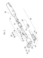
- FIG. 2 is an exploded perspective view the lancet-separable lancet device according to an exemplary embodiment of the present invention
- FIG. 3 is a cross-sectional view of the assembly of the parts shown in FIG. 1 .
- a lance-separable lancet device 100 largely includes a lancet holder 110, an operating mechanism 120, a housing 130, an operation switch 170, a depth adjusting member 140, a cover 150, a coupling portion 160, and a lancet separation mechanism 180.
- the lancet holder 110 has a lancet seat 111 to mount a lancet 10 at one end and is disposed at a side in the housing 130.
- the lancet 10 which is disposable, has a lancet needle 12 at one end of a lancet body 11 with a predetermined length and the lancet needle 12 is combined with a protection cap (not shown).
- the protection cap is coupled to one end of the lancet needle 12 by insert injection, and according to this configuration, the protection cap can be separated from the lancet needle 12 even by a small force.
- the operating mechanism 120 is disposed at the other end of the lancet holder 110, has a structure for loading and releasing the lancet holder 110 along a predetermined path, and for this operation, it includes a plurality of springs 121, 122, and 123, as shown in FIG. 1 .
- the housing 130 receives the operating mechanism 120, with the lancet holder 110 coupled to one end, and the operation switch 170 operating with the operating mechanism 120 is disposed at a predetermined position.
- the operation switch 170 is connected to the operating mechanism 120 and operates the operating mechanism 120 by pressing it.
- the springs 121, 122, and 123 are instantaneously compressed, and extend and hit a movable shaft 125 under which a shock transmission rod 124 is positioned, the movable shaft 125 hits the lancet holder 110 holding the lancet 10, and the lancet 10 protrudes outward.
- the depth adjusting member 140 adjusts the penetration depth under the skin of the lancet needle 12.
- the cover 150 covers one end of the housing 130 and has a through-hole 152 at the center through which the lancet needle 12 of the lancet 10 instantaneously protrudes and a plurality of protrusions 153 radially formed and arranged at predetermined angles on the front side.
- the coupling portion 160 hinges one end of the housing 130 and the cover 150.
- the lancet separation mechanism 180 is disposed at the other side of the lancet holder 110, and is inserted into the lancet holder 110 through a separation hole 119 of the lancet holder 110 and separates the lancet 10 from the lancet holder 110 by pressing the lancet 10.
- the lancet separation mechanism 180 includes an L-shaped bar 181 with an end 181 a inserted in the separation hole 118 of the lancet holder 110 and a lancet separation switch 182 that has a fitting recess 182a fitted to the other end 181 b with a step of the L-shaped bar 181 and is in close contact with the outer side of the housing 130.
- the end 181 a of the L-shaped bar 181 is elongated in the longitudinal direction of the movable shaft 125 to be able to press the bottom of the lancet holder 110 through the separation hole 119 of the lancet holder 110 and the other end 181 b is formed perpendicularly from the end 181 a, has a step, and is fitted in the fitting recess 182a of the lancet separation switch 182.
- the lancet separation switch 182 is fitted in a coupling hole 139 formed on the outer side of the housing 130 and coupled to the other end 181 b of the bar 181, such that it inserts the bar 181 into the lancet holder 110 through the separation hole 119 of the lancet holder 110, when being moved in the longitudinal direction of the bar 181 by a user.
- An elastic member 183 may be further provided so that the lancet separation switch 182 moved by a user can smoothly return to the initial position.
- the elastic member 183 which is a spring, has one end being in contact with the other end of the depth adjusting member 140 and the other end coupled to a side of the bar 181 or the lancet separation switch 182, such that it returns the bar 181 inserted in the separation hole 119 of the lancet holder 110 to the initial position.
- the elastic member 183 is combined with the lancet separation switch 182 or combined with the bar 181, as in an exemplary embodiment of the present invention, and is disposed in the internal space between the bar 181 and the housing 130 in the longitudinal direction of the bar 181. Further, the elastic member 183 may be compressed in the movement direction of the lancet separation switch 182 or may be returned by the elastic force of the elastic member 183 after compressed.
- Wrinkles 182b are formed perpendicular to the longitudinal direction on the outer side of the lancet separation switch 182 and increase the friction force between the user's fingers and the surface, such that the lancet separation switch 128 can be easily longitudinally moved.
- the lancet separation switch 182 when the lancet separation switch 182 is pushed with the lancet 10 spaced at a predetermined distance from the bar 182, the bar 181 is moved to the lancet 10 through the separation hole 119, such that the lancet 10 can be separated from the lancet holder 110.
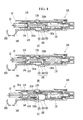
- FIG. 4 is a status view for illustrating how to use a lancet separation mechanism of the lancet-separable lancet device according to an exemplary embodiment of the present invention.
- the cover 150 is opened and the lancet 10 is mounted on the lancet holder 110 (a).
- the lancet separation switch 180 is pushed to the lancet 10 so that the bar 181 is inserted into the lancet holder 110 through the separation hole 119. Accordingly, the lancet 10 is separated from the lancet holder 110 by the bar 181 and the elastic member 183 is compressed in the movement direction of the lancet separation switch 182 and the bar 181 (b).
- the elastic member 183 When the lancet separation switch 182 is released, after the lancet 10 is separated, the elastic member 183 returns to the initial status by the restoring force, and accordingly, the lancet separation switch 182 and the bar 181 are also moved in the direction opposite to the compression direction of the elastic member 183, returning to the initial position (c).
- the lancet separation switch 182 is used while the lancet 10 that finished taking blood is separated from the lancet device 100, it is possible to minimize the possibility of sticking the skin of the subject or people around with the lancet needle 12.
- the lancet 10 since it is required to pull out the lancet 10 to separate it from the lancet device 100 after taking blood, there is a problem in that the lancet 10 may spring in separating or a user may be pricked by the lancet needle 12; however, in the present invention, a subject can not only easily use the lancet separation switch 182, but stably separate the lancet 10.
Landscapes
- Health & Medical Sciences (AREA)
- Life Sciences & Earth Sciences (AREA)
- Heart & Thoracic Surgery (AREA)
- Medical Informatics (AREA)
- Biophysics (AREA)
- Pathology (AREA)
- Engineering & Computer Science (AREA)
- Biomedical Technology (AREA)
- Hematology (AREA)
- Physics & Mathematics (AREA)
- Molecular Biology (AREA)
- Surgery (AREA)
- Animal Behavior & Ethology (AREA)
- General Health & Medical Sciences (AREA)
- Public Health (AREA)
- Veterinary Medicine (AREA)
- Measurement Of The Respiration, Hearing Ability, Form, And Blood Characteristics Of Living Organisms (AREA)
Abstract
Description
- The present invention relates to a lancet-separable lancet device. More particularly, the present invention relates to a lancet-separable lancet device which can minimize the danger of being pricked or touched by a lancet needle due to spring of a lancet when the lancet is separated.
- In general, chronic diabetics have to measure the blood glucose level by performing a blood sugar test by themselves everyday at home and to perform disease control in order to keep a predetermined blood glucose level.
- They have to collect blood for the blood glucose test, and this case, generally, they stick a disposable lancet into the skin of a portion, usually a finger, of their bodies, take and put a small amount of capillary blood onto a strip, and then measure the blood glucose level using a blood glucose meter with the strip mounted.
- A lancing device is generally used as the device for taking blood.
- The lancing device is composed of a lancet holder mounted with a disposable lancet, a cover that covers a lancet and has a hole through which only the tip of a needle protrudes to penetrate a skin, and a spring and a releasing member that provide a penetration force. The disposable lancet has lancet needle at one end of a lancet body and a protection cap is combined with the lancet needle.
- According to the lancing devices having this configuration in the related art, a user removes the cover from a lancing device, mounts a disposable lancet onto the lancet holder, attaches the cover with the spring compressed, brings the lancet in close contact with a portion with many capillaries such as fingers, and then releases the disposable lancet by pulling a releasing switch, such that the lancet penetrates the skin.
- Lancets are supposed to be disposable to prevent infection, because they penetrate the skin of a human.
- Therefore, a subject should remove a lancet after using it with a lancing device.
- However, a subject should remove a lancet by hand when separating a disposable lancet used for taking blood and the lancet is separated and springs by the internal elastic force, such that there is some possibility that the lancet pricks the skin of the subject or people around, which causes a serious problem in safety.
- In particular, when an examiner (the third person) takes blood, the examiner's hand may be pricked or touched by the needle with the blood of the subject thereon when separating a disposable lancet from a lancing device, such that there is a problem in that viruses may be transmitted.
- The present invention has been made in an effort to provide a lancet-separable lancet device having advantages of being able to minimize the danger of being pricked or touched by a lancet needle due to spring of a lancet when the lancet is separated.
- An exemplary embodiment of the present invention provides a lancet-separable lancet device including: a lancet holder having a lancet seat to mount a lancet at one end and a separation hole at the other end; and a lancet separation mechanism inserted into the separation hole of the lancet holder and separating the lancet from the lancet holder by pressing the lancet.
- According to the present invention described above, since the lancet separation switch is used while the lancet that finished taking blood is separated from the lancet device, it is possible to minimize the possibility of sticking the skin of a subject or people around with the lancet needle, the subject can stably separate the lancet, and it is possible to minimize infection by viruses due to the reason that the examiner's fingers are pricked or touched by the lancet needle used for taking blood.
-
-
FIG. 1 is a perspective view a lancet-separable lancet device according to an exemplary embodiment of the present invention. -
FIG. 2 is an exploded perspective view the lancet-separable lancet device according to an exemplary embodiment of the present invention. -
FIG. 3 is a cross-sectional view of the assembly of the parts shown inFIG. 1 . -
FIG. 4 is a status view for illustrating how to use a lancet separation mechanism of the lancet-separable lancet device according to an exemplary embodiment of the present invention. - Hereinafter, exemplary embodiment of the present invention will be described in detail with reference to the accompanying drawings. First, when giving the components in the drawings reference numerals, it should be noted that the same reference numerals are given to reference numerals as same as possible even if they are shown in different drawings. Further, the in description of the present invention, the detailed description of related well-known configurations and functions is not provided, when it is determined as making the scope of the present invention unclear.
-
FIG. 1 is a perspective view a lancet-separable lancet device according to an exemplary embodiment of the present invention,FIG. 2 is an exploded perspective view the lancet-separable lancet device according to an exemplary embodiment of the present invention, andFIG. 3 is a cross-sectional view of the assembly of the parts shown inFIG. 1 . - Referring to
FIGS. 1 to 3 , a lance-separable lancet device 100 according to an exemplary embodiment of the present invention largely includes alancet holder 110, anoperating mechanism 120, ahousing 130, anoperation switch 170, adepth adjusting member 140, acover 150, acoupling portion 160, and alancet separation mechanism 180. - The
lancet holder 110 has alancet seat 111 to mount alancet 10 at one end and is disposed at a side in thehousing 130. - The
lancet 10, which is disposable, has alancet needle 12 at one end of a lancet body 11 with a predetermined length and thelancet needle 12 is combined with a protection cap (not shown). - The protection cap is coupled to one end of the
lancet needle 12 by insert injection, and according to this configuration, the protection cap can be separated from thelancet needle 12 even by a small force. - The
operating mechanism 120 is disposed at the other end of thelancet holder 110, has a structure for loading and releasing thelancet holder 110 along a predetermined path, and for this operation, it includes a plurality ofsprings FIG. 1 . - The
housing 130, a cylinder sized to be portable by a user, receives theoperating mechanism 120, with thelancet holder 110 coupled to one end, and theoperation switch 170 operating with theoperating mechanism 120 is disposed at a predetermined position. - The
operation switch 170 is connected to theoperating mechanism 120 and operates theoperating mechanism 120 by pressing it. - When a user presses the
operation switch 170, thesprings movable shaft 125 under which ashock transmission rod 124 is positioned, themovable shaft 125 hits thelancet holder 110 holding thelancet 10, and thelancet 10 protrudes outward. - The
depth adjusting member 140 adjusts the penetration depth under the skin of thelancet needle 12. - The
cover 150 covers one end of thehousing 130 and has a through-hole 152 at the center through which thelancet needle 12 of thelancet 10 instantaneously protrudes and a plurality ofprotrusions 153 radially formed and arranged at predetermined angles on the front side. - The
coupling portion 160 hinges one end of thehousing 130 and thecover 150. - The
lancet separation mechanism 180 is disposed at the other side of thelancet holder 110, and is inserted into thelancet holder 110 through aseparation hole 119 of thelancet holder 110 and separates thelancet 10 from thelancet holder 110 by pressing thelancet 10. To this end, thelancet separation mechanism 180 includes an L-shaped bar 181 with anend 181 a inserted in the separation hole 118 of thelancet holder 110 and alancet separation switch 182 that has afitting recess 182a fitted to theother end 181 b with a step of the L-shaped bar 181 and is in close contact with the outer side of thehousing 130. - The
end 181 a of the L-shaped bar 181 is elongated in the longitudinal direction of themovable shaft 125 to be able to press the bottom of thelancet holder 110 through theseparation hole 119 of thelancet holder 110 and theother end 181 b is formed perpendicularly from theend 181 a, has a step, and is fitted in thefitting recess 182a of thelancet separation switch 182. - The
lancet separation switch 182 is fitted in acoupling hole 139 formed on the outer side of thehousing 130 and coupled to theother end 181 b of thebar 181, such that it inserts thebar 181 into thelancet holder 110 through theseparation hole 119 of thelancet holder 110, when being moved in the longitudinal direction of thebar 181 by a user. - An
elastic member 183 may be further provided so that thelancet separation switch 182 moved by a user can smoothly return to the initial position. Theelastic member 183, which is a spring, has one end being in contact with the other end of thedepth adjusting member 140 and the other end coupled to a side of thebar 181 or thelancet separation switch 182, such that it returns thebar 181 inserted in theseparation hole 119 of thelancet holder 110 to the initial position. - In other words, the
elastic member 183 is combined with thelancet separation switch 182 or combined with thebar 181, as in an exemplary embodiment of the present invention, and is disposed in the internal space between thebar 181 and thehousing 130 in the longitudinal direction of thebar 181. Further, theelastic member 183 may be compressed in the movement direction of thelancet separation switch 182 or may be returned by the elastic force of theelastic member 183 after compressed. - Wrinkles 182b are formed perpendicular to the longitudinal direction on the outer side of the
lancet separation switch 182 and increase the friction force between the user's fingers and the surface, such that the lancet separation switch 128 can be easily longitudinally moved. - As shown in
FIG. 3 , when thelancet separation switch 182 is pushed with thelancet 10 spaced at a predetermined distance from thebar 182, thebar 181 is moved to thelancet 10 through theseparation hole 119, such that thelancet 10 can be separated from thelancet holder 110. - How to use the
lancet separation mechanism 180 is described below in more detail with reference toFIG. 4 . -
FIG. 4 is a status view for illustrating how to use a lancet separation mechanism of the lancet-separable lancet device according to an exemplary embodiment of the present invention. - First, the
cover 150 is opened and thelancet 10 is mounted on the lancet holder 110 (a). - Thereafter, the
cover 150 is closed and the under-skin penetration depth of thelancet needle 12 is adjusted, and then theoperating mechanism 120 is operated by pressing theoperation switch 170, thereby taking blood. The detailed description of this step is not provided. - Next, it is required to separate the
lancet 10 from thelancet device 100, in which thelancet separation switch 180 is pushed to thelancet 10 so that thebar 181 is inserted into thelancet holder 110 through theseparation hole 119. Accordingly, thelancet 10 is separated from thelancet holder 110 by thebar 181 and theelastic member 183 is compressed in the movement direction of thelancet separation switch 182 and the bar 181 (b). - When the
lancet separation switch 182 is released, after thelancet 10 is separated, theelastic member 183 returns to the initial status by the restoring force, and accordingly, thelancet separation switch 182 and thebar 181 are also moved in the direction opposite to the compression direction of theelastic member 183, returning to the initial position (c). - According to the structure and the operation way of the
lancet separation mechanism 180, since thelancet separation switch 182 is used while thelancet 10 that finished taking blood is separated from thelancet device 100, it is possible to minimize the possibility of sticking the skin of the subject or people around with thelancet needle 12. - That is, according to the existing products, since it is required to pull out the
lancet 10 to separate it from thelancet device 100 after taking blood, there is a problem in that thelancet 10 may spring in separating or a user may be pricked by thelancet needle 12; however, in the present invention, a subject can not only easily use thelancet separation switch 182, but stably separate thelancet 10. - Therefore, it is possible to minimize infection by viruses due to the reason that the examiner's fingers are pricked or touched by the
lancet needle 12 used for taking blood. - The above description is an example of the spirit of the present invention and may be changed and modified in various ways by those skilled in the art without departing from the scope of the present invention. Therefore, the exemplary embodiments described herein are not for limiting the spirit of the present invention, but for explaining the present invention and the scope of the present invention is not limited to the exemplary embodiments. The protective range of the present invention should be construed by claims and the equivalents should be construed as being included in the scope of the present invention.
- While this invention has been described in connection with what is presently considered to be practical exemplary embodiments, it is to be understood that the invention is not limited to the disclosed embodiments, but, on the contrary, is intended to cover various modifications and equivalent arrangements included within the spirit and scope of the appended claims.
Claims (6)
- A lancet-separable lancet device, comprising: a lancet holder having a lancet seat to mount a lancet at one end and a separation hole at the other end; and a lancet separation mechanism inserted into the separation hole of the lancet holder and separating the lancet from the lancet holder by pressing the lancet.
- The device of claim 1, wherein the lancet separation mechanism includes:a bar having one end that is inserted into the lancet holder through the separation hole of the lancet holdera lancet separation switch coupled to the other end of the bar and moving one end of the bar to the lancet.
- The device of 2, wherein the bar is formed in an L-shape and has a step at the other end and the lancet separation switch has a fitting recess therein in which the other end of the bar is fitted.
- The device of 3, wherein the lancet separation switch is fitted longitudinally in a coupling hole formed on the outer side of the housing and movable in the longitudinal direction.
- The device of 2, wherein the lancet separation mechanism
further includes an elastic member combined with the bar or the lancet separation switch and returning the bar inserted in the lancet holder to the initial position. - The device of 5, wherein wrinkles perpendicular to the longitudinal direction are formed on the outer side of the lancet separation switch which is fitted on the outer side of the housing.
Applications Claiming Priority (2)
| Application Number | Priority Date | Filing Date | Title |
|---|---|---|---|
| KR1020100129246A KR101214652B1 (en) | 2010-12-16 | 2010-12-16 | Lancet apparatus for separating lancet |
| PCT/KR2011/006935 WO2012081808A1 (en) | 2010-12-16 | 2011-09-20 | Lancet device capable of lancet detachment |
Publications (3)
| Publication Number | Publication Date |
|---|---|
| EP2653099A1 true EP2653099A1 (en) | 2013-10-23 |
| EP2653099A4 EP2653099A4 (en) | 2014-05-07 |
| EP2653099B1 EP2653099B1 (en) | 2015-12-16 |
Family
ID=46244880
Family Applications (1)
| Application Number | Title | Priority Date | Filing Date |
|---|---|---|---|
| EP11848367.6A Not-in-force EP2653099B1 (en) | 2010-12-16 | 2011-09-20 | Lancet device capable of lancet detachment |
Country Status (5)
| Country | Link |
|---|---|
| US (1) | US20130267976A1 (en) |
| EP (1) | EP2653099B1 (en) |
| KR (1) | KR101214652B1 (en) |
| CN (1) | CN103347445B (en) |
| WO (1) | WO2012081808A1 (en) |
Families Citing this family (1)
| Publication number | Priority date | Publication date | Assignee | Title |
|---|---|---|---|---|
| CN103371831B (en) * | 2012-04-12 | 2016-03-23 | 上海宝尔生贸易有限公司 | A kind of safety blood taking pen |
Family Cites Families (9)
| Publication number | Priority date | Publication date | Assignee | Title |
|---|---|---|---|---|
| US5196025A (en) * | 1990-05-21 | 1993-03-23 | Ryder International Corporation | Lancet actuator with retractable mechanism |
| US5984940A (en) * | 1997-05-29 | 1999-11-16 | Atrion Medical Products, Inc. | Lancet device |
| CN2579344Y (en) * | 2002-11-29 | 2003-10-15 | 施国平 | Improved schbil disposable adjustable safety autoamtic blood taking needle |
| US20070083222A1 (en) * | 2005-06-16 | 2007-04-12 | Stat Medical Devices, Inc. | Lancet device, removal system for lancet device, and method |
| CN200945164Y (en) * | 2006-08-14 | 2007-09-12 | 施国平 | Disposable safety blood taking needle capable of adjusting puncture depth |
| US9179867B2 (en) * | 2007-06-19 | 2015-11-10 | Stat Medical Devices, Inc. | Lancet device with depth adjustment and lancet removal system and method |
| KR20090049505A (en) * | 2007-11-13 | 2009-05-18 | 서지희 | Blood collection lancet device and blood collection method using the blood collection lancet device |
| KR100932946B1 (en) * | 2008-03-19 | 2009-12-21 | 홍관호 | Blood collector |
| KR100912202B1 (en) * | 2008-07-03 | 2009-08-14 | (주)보성메디텍 | Lancet integrated cap and painless blood collector |
-
2010
- 2010-12-16 KR KR1020100129246A patent/KR101214652B1/en not_active Expired - Fee Related
-
2011
- 2011-09-20 WO PCT/KR2011/006935 patent/WO2012081808A1/en not_active Ceased
- 2011-09-20 EP EP11848367.6A patent/EP2653099B1/en not_active Not-in-force
- 2011-09-20 CN CN201180060503.2A patent/CN103347445B/en not_active Expired - Fee Related
- 2011-09-20 US US13/995,151 patent/US20130267976A1/en not_active Abandoned
Also Published As
| Publication number | Publication date |
|---|---|
| KR20120067700A (en) | 2012-06-26 |
| US20130267976A1 (en) | 2013-10-10 |
| CN103347445A (en) | 2013-10-09 |
| CN103347445B (en) | 2015-05-27 |
| EP2653099B1 (en) | 2015-12-16 |
| KR101214652B1 (en) | 2012-12-24 |
| EP2653099A4 (en) | 2014-05-07 |
| WO2012081808A1 (en) | 2012-06-21 |
Similar Documents
| Publication | Publication Date | Title |
|---|---|---|
| EP1827234B1 (en) | Skin pricking apparatus | |
| US5871494A (en) | Reproducible lancing for sampling blood | |
| AU2011209847B2 (en) | Analyte measurement device with a single shot actuator | |
| US8828038B2 (en) | Lancing device | |
| CN100508888C (en) | Dampening and retraction mechanism for a lancing device | |
| US8303615B2 (en) | Lancet-eject mechanism | |
| KR20210032258A (en) | Pressure-Actuated Disposable Painless Lancet With Improved Performance And Construction | |
| CN101163447A (en) | Lancet Release Mechanism | |
| US9375175B2 (en) | Lancing device | |
| US20130281882A1 (en) | Lancet device | |
| EP2653100A1 (en) | Lancet device capable of adjusting subcutaneous peneration depth | |
| RU2717636C1 (en) | Disposable lancet for painless skin puncture and piercing instrument comprising said lancet | |
| EP2653099B1 (en) | Lancet device capable of lancet detachment | |
| EP2381847B1 (en) | Skin pricking device | |
| US9351678B2 (en) | Lancet holder and lancet device including the same | |
| US11672451B2 (en) | Lancing device | |
| KR20200016070A (en) | Pain-free blood collection device | |
| WO2009148431A1 (en) | Lancing device | |
| GB2373731A (en) | Apparatus and method for sampling blood | |
| HK1171933B (en) | Analyte measurement device with a single shot actuator |
Legal Events
| Date | Code | Title | Description |
|---|---|---|---|
| PUAI | Public reference made under article 153(3) epc to a published international application that has entered the european phase |
Free format text: ORIGINAL CODE: 0009012 |
|
| 17P | Request for examination filed |
Effective date: 20130704 |
|
| AK | Designated contracting states |
Kind code of ref document: A1 Designated state(s): AL AT BE BG CH CY CZ DE DK EE ES FI FR GB GR HR HU IE IS IT LI LT LU LV MC MK MT NL NO PL PT RO RS SE SI SK SM TR |
|
| DAX | Request for extension of the european patent (deleted) | ||
| A4 | Supplementary search report drawn up and despatched |
Effective date: 20140403 |
|
| RIC1 | Information provided on ipc code assigned before grant |
Ipc: A61B 5/151 20060101AFI20140328BHEP |
|
| GRAP | Despatch of communication of intention to grant a patent |
Free format text: ORIGINAL CODE: EPIDOSNIGR1 |
|
| INTG | Intention to grant announced |
Effective date: 20150611 |
|
| GRAS | Grant fee paid |
Free format text: ORIGINAL CODE: EPIDOSNIGR3 |
|
| GRAA | (expected) grant |
Free format text: ORIGINAL CODE: 0009210 |
|
| AK | Designated contracting states |
Kind code of ref document: B1 Designated state(s): AL AT BE BG CH CY CZ DE DK EE ES FI FR GB GR HR HU IE IS IT LI LT LU LV MC MK MT NL NO PL PT RO RS SE SI SK SM TR |
|
| REG | Reference to a national code |
Ref country code: GB Ref legal event code: FG4D |
|
| REG | Reference to a national code |
Ref country code: CH Ref legal event code: EP |
|
| REG | Reference to a national code |
Ref country code: IE Ref legal event code: FG4D |
|
| REG | Reference to a national code |
Ref country code: AT Ref legal event code: REF Ref document number: 765114 Country of ref document: AT Kind code of ref document: T Effective date: 20160115 |
|
| REG | Reference to a national code |
Ref country code: DE Ref legal event code: R096 Ref document number: 602011022152 Country of ref document: DE |
|
| REG | Reference to a national code |
Ref country code: NL Ref legal event code: MP Effective date: 20151216 |
|
| REG | Reference to a national code |
Ref country code: LT Ref legal event code: MG4D |
|
| PG25 | Lapsed in a contracting state [announced via postgrant information from national office to epo] |
Ref country code: NO Free format text: LAPSE BECAUSE OF FAILURE TO SUBMIT A TRANSLATION OF THE DESCRIPTION OR TO PAY THE FEE WITHIN THE PRESCRIBED TIME-LIMIT Effective date: 20160316 Ref country code: HR Free format text: LAPSE BECAUSE OF FAILURE TO SUBMIT A TRANSLATION OF THE DESCRIPTION OR TO PAY THE FEE WITHIN THE PRESCRIBED TIME-LIMIT Effective date: 20151216 Ref country code: LT Free format text: LAPSE BECAUSE OF FAILURE TO SUBMIT A TRANSLATION OF THE DESCRIPTION OR TO PAY THE FEE WITHIN THE PRESCRIBED TIME-LIMIT Effective date: 20151216 |
|
| REG | Reference to a national code |
Ref country code: AT Ref legal event code: MK05 Ref document number: 765114 Country of ref document: AT Kind code of ref document: T Effective date: 20151216 |
|
| PG25 | Lapsed in a contracting state [announced via postgrant information from national office to epo] |
Ref country code: GR Free format text: LAPSE BECAUSE OF FAILURE TO SUBMIT A TRANSLATION OF THE DESCRIPTION OR TO PAY THE FEE WITHIN THE PRESCRIBED TIME-LIMIT Effective date: 20160317 Ref country code: LV Free format text: LAPSE BECAUSE OF FAILURE TO SUBMIT A TRANSLATION OF THE DESCRIPTION OR TO PAY THE FEE WITHIN THE PRESCRIBED TIME-LIMIT Effective date: 20151216 Ref country code: NL Free format text: LAPSE BECAUSE OF FAILURE TO SUBMIT A TRANSLATION OF THE DESCRIPTION OR TO PAY THE FEE WITHIN THE PRESCRIBED TIME-LIMIT Effective date: 20151216 Ref country code: FI Free format text: LAPSE BECAUSE OF FAILURE TO SUBMIT A TRANSLATION OF THE DESCRIPTION OR TO PAY THE FEE WITHIN THE PRESCRIBED TIME-LIMIT Effective date: 20151216 Ref country code: SE Free format text: LAPSE BECAUSE OF FAILURE TO SUBMIT A TRANSLATION OF THE DESCRIPTION OR TO PAY THE FEE WITHIN THE PRESCRIBED TIME-LIMIT Effective date: 20151216 Ref country code: RS Free format text: LAPSE BECAUSE OF FAILURE TO SUBMIT A TRANSLATION OF THE DESCRIPTION OR TO PAY THE FEE WITHIN THE PRESCRIBED TIME-LIMIT Effective date: 20151216 |
|
| PG25 | Lapsed in a contracting state [announced via postgrant information from national office to epo] |
Ref country code: ES Free format text: LAPSE BECAUSE OF FAILURE TO SUBMIT A TRANSLATION OF THE DESCRIPTION OR TO PAY THE FEE WITHIN THE PRESCRIBED TIME-LIMIT Effective date: 20151216 Ref country code: CZ Free format text: LAPSE BECAUSE OF FAILURE TO SUBMIT A TRANSLATION OF THE DESCRIPTION OR TO PAY THE FEE WITHIN THE PRESCRIBED TIME-LIMIT Effective date: 20151216 Ref country code: IT Free format text: LAPSE BECAUSE OF FAILURE TO SUBMIT A TRANSLATION OF THE DESCRIPTION OR TO PAY THE FEE WITHIN THE PRESCRIBED TIME-LIMIT Effective date: 20151216 |
|
| PG25 | Lapsed in a contracting state [announced via postgrant information from national office to epo] |
Ref country code: SK Free format text: LAPSE BECAUSE OF FAILURE TO SUBMIT A TRANSLATION OF THE DESCRIPTION OR TO PAY THE FEE WITHIN THE PRESCRIBED TIME-LIMIT Effective date: 20151216 Ref country code: SM Free format text: LAPSE BECAUSE OF FAILURE TO SUBMIT A TRANSLATION OF THE DESCRIPTION OR TO PAY THE FEE WITHIN THE PRESCRIBED TIME-LIMIT Effective date: 20151216 Ref country code: RO Free format text: LAPSE BECAUSE OF FAILURE TO SUBMIT A TRANSLATION OF THE DESCRIPTION OR TO PAY THE FEE WITHIN THE PRESCRIBED TIME-LIMIT Effective date: 20151216 Ref country code: AT Free format text: LAPSE BECAUSE OF FAILURE TO SUBMIT A TRANSLATION OF THE DESCRIPTION OR TO PAY THE FEE WITHIN THE PRESCRIBED TIME-LIMIT Effective date: 20151216 Ref country code: EE Free format text: LAPSE BECAUSE OF FAILURE TO SUBMIT A TRANSLATION OF THE DESCRIPTION OR TO PAY THE FEE WITHIN THE PRESCRIBED TIME-LIMIT Effective date: 20151216 Ref country code: PT Free format text: LAPSE BECAUSE OF FAILURE TO SUBMIT A TRANSLATION OF THE DESCRIPTION OR TO PAY THE FEE WITHIN THE PRESCRIBED TIME-LIMIT Effective date: 20160418 Ref country code: IS Free format text: LAPSE BECAUSE OF FAILURE TO SUBMIT A TRANSLATION OF THE DESCRIPTION OR TO PAY THE FEE WITHIN THE PRESCRIBED TIME-LIMIT Effective date: 20160416 |
|
| REG | Reference to a national code |
Ref country code: DE Ref legal event code: R097 Ref document number: 602011022152 Country of ref document: DE |
|
| PLBE | No opposition filed within time limit |
Free format text: ORIGINAL CODE: 0009261 |
|
| STAA | Information on the status of an ep patent application or granted ep patent |
Free format text: STATUS: NO OPPOSITION FILED WITHIN TIME LIMIT |
|
| PG25 | Lapsed in a contracting state [announced via postgrant information from national office to epo] |
Ref country code: DK Free format text: LAPSE BECAUSE OF FAILURE TO SUBMIT A TRANSLATION OF THE DESCRIPTION OR TO PAY THE FEE WITHIN THE PRESCRIBED TIME-LIMIT Effective date: 20151216 Ref country code: PL Free format text: LAPSE BECAUSE OF FAILURE TO SUBMIT A TRANSLATION OF THE DESCRIPTION OR TO PAY THE FEE WITHIN THE PRESCRIBED TIME-LIMIT Effective date: 20151216 |
|
| 26N | No opposition filed |
Effective date: 20160919 |
|
| PG25 | Lapsed in a contracting state [announced via postgrant information from national office to epo] |
Ref country code: BE Free format text: LAPSE BECAUSE OF FAILURE TO SUBMIT A TRANSLATION OF THE DESCRIPTION OR TO PAY THE FEE WITHIN THE PRESCRIBED TIME-LIMIT Effective date: 20151216 |
|
| PG25 | Lapsed in a contracting state [announced via postgrant information from national office to epo] |
Ref country code: SI Free format text: LAPSE BECAUSE OF FAILURE TO SUBMIT A TRANSLATION OF THE DESCRIPTION OR TO PAY THE FEE WITHIN THE PRESCRIBED TIME-LIMIT Effective date: 20151216 |
|
| PG25 | Lapsed in a contracting state [announced via postgrant information from national office to epo] |
Ref country code: MC Free format text: LAPSE BECAUSE OF FAILURE TO SUBMIT A TRANSLATION OF THE DESCRIPTION OR TO PAY THE FEE WITHIN THE PRESCRIBED TIME-LIMIT Effective date: 20151216 |
|
| REG | Reference to a national code |
Ref country code: CH Ref legal event code: PL |
|
| GBPC | Gb: european patent ceased through non-payment of renewal fee |
Effective date: 20160920 |
|
| REG | Reference to a national code |
Ref country code: IE Ref legal event code: MM4A |
|
| REG | Reference to a national code |
Ref country code: FR Ref legal event code: ST Effective date: 20170531 |
|
| PG25 | Lapsed in a contracting state [announced via postgrant information from national office to epo] |
Ref country code: GB Free format text: LAPSE BECAUSE OF NON-PAYMENT OF DUE FEES Effective date: 20160920 Ref country code: IE Free format text: LAPSE BECAUSE OF NON-PAYMENT OF DUE FEES Effective date: 20160920 Ref country code: FR Free format text: LAPSE BECAUSE OF NON-PAYMENT OF DUE FEES Effective date: 20160930 Ref country code: LI Free format text: LAPSE BECAUSE OF NON-PAYMENT OF DUE FEES Effective date: 20160930 Ref country code: CH Free format text: LAPSE BECAUSE OF NON-PAYMENT OF DUE FEES Effective date: 20160930 |
|
| PG25 | Lapsed in a contracting state [announced via postgrant information from national office to epo] |
Ref country code: LU Free format text: LAPSE BECAUSE OF NON-PAYMENT OF DUE FEES Effective date: 20160920 |
|
| PG25 | Lapsed in a contracting state [announced via postgrant information from national office to epo] |
Ref country code: HU Free format text: LAPSE BECAUSE OF FAILURE TO SUBMIT A TRANSLATION OF THE DESCRIPTION OR TO PAY THE FEE WITHIN THE PRESCRIBED TIME-LIMIT; INVALID AB INITIO Effective date: 20110920 Ref country code: CY Free format text: LAPSE BECAUSE OF FAILURE TO SUBMIT A TRANSLATION OF THE DESCRIPTION OR TO PAY THE FEE WITHIN THE PRESCRIBED TIME-LIMIT Effective date: 20151216 |
|
| PG25 | Lapsed in a contracting state [announced via postgrant information from national office to epo] |
Ref country code: TR Free format text: LAPSE BECAUSE OF FAILURE TO SUBMIT A TRANSLATION OF THE DESCRIPTION OR TO PAY THE FEE WITHIN THE PRESCRIBED TIME-LIMIT Effective date: 20151216 Ref country code: MK Free format text: LAPSE BECAUSE OF FAILURE TO SUBMIT A TRANSLATION OF THE DESCRIPTION OR TO PAY THE FEE WITHIN THE PRESCRIBED TIME-LIMIT Effective date: 20151216 Ref country code: MT Free format text: LAPSE BECAUSE OF NON-PAYMENT OF DUE FEES Effective date: 20160930 |
|
| PG25 | Lapsed in a contracting state [announced via postgrant information from national office to epo] |
Ref country code: BG Free format text: LAPSE BECAUSE OF FAILURE TO SUBMIT A TRANSLATION OF THE DESCRIPTION OR TO PAY THE FEE WITHIN THE PRESCRIBED TIME-LIMIT Effective date: 20151216 |
|
| PG25 | Lapsed in a contracting state [announced via postgrant information from national office to epo] |
Ref country code: AL Free format text: LAPSE BECAUSE OF FAILURE TO SUBMIT A TRANSLATION OF THE DESCRIPTION OR TO PAY THE FEE WITHIN THE PRESCRIBED TIME-LIMIT Effective date: 20151216 |
|
| PGFP | Annual fee paid to national office [announced via postgrant information from national office to epo] |
Ref country code: DE Payment date: 20180904 Year of fee payment: 8 |
|
| REG | Reference to a national code |
Ref country code: DE Ref legal event code: R119 Ref document number: 602011022152 Country of ref document: DE |
|
| PG25 | Lapsed in a contracting state [announced via postgrant information from national office to epo] |
Ref country code: DE Free format text: LAPSE BECAUSE OF NON-PAYMENT OF DUE FEES Effective date: 20200401 |