EP2653097A1 - Biological information monitoring apparatus - Google Patents
Biological information monitoring apparatus Download PDFInfo
- Publication number
- EP2653097A1 EP2653097A1 EP13163712.6A EP13163712A EP2653097A1 EP 2653097 A1 EP2653097 A1 EP 2653097A1 EP 13163712 A EP13163712 A EP 13163712A EP 2653097 A1 EP2653097 A1 EP 2653097A1
- Authority
- EP
- European Patent Office
- Prior art keywords
- biological information
- measurer
- monitoring apparatus
- time
- calibration process
- Prior art date
- Legal status (The legal status is an assumption and is not a legal conclusion. Google has not performed a legal analysis and makes no representation as to the accuracy of the status listed.)
- Withdrawn
Links
Images



Classifications
-
- A—HUMAN NECESSITIES
- A61—MEDICAL OR VETERINARY SCIENCE; HYGIENE
- A61B—DIAGNOSIS; SURGERY; IDENTIFICATION
- A61B5/00—Measuring for diagnostic purposes; Identification of persons
- A61B5/72—Signal processing specially adapted for physiological signals or for diagnostic purposes
-
- A—HUMAN NECESSITIES
- A61—MEDICAL OR VETERINARY SCIENCE; HYGIENE
- A61B—DIAGNOSIS; SURGERY; IDENTIFICATION
- A61B5/00—Measuring for diagnostic purposes; Identification of persons
- A61B5/08—Measuring devices for evaluating the respiratory organs
- A61B5/082—Evaluation by breath analysis, e.g. determination of the chemical composition of exhaled breath
-
- A—HUMAN NECESSITIES
- A61—MEDICAL OR VETERINARY SCIENCE; HYGIENE
- A61B—DIAGNOSIS; SURGERY; IDENTIFICATION
- A61B5/00—Measuring for diagnostic purposes; Identification of persons
- A61B5/145—Measuring characteristics of blood in vivo, e.g. gas concentration or pH-value ; Measuring characteristics of body fluids or tissues, e.g. interstitial fluid or cerebral tissue
- A61B5/1495—Calibrating or testing of in-vivo probes
-
- A—HUMAN NECESSITIES
- A61—MEDICAL OR VETERINARY SCIENCE; HYGIENE
- A61B—DIAGNOSIS; SURGERY; IDENTIFICATION
- A61B5/00—Measuring for diagnostic purposes; Identification of persons
- A61B5/74—Details of notification to user or communication with user or patient; User input means
- A61B5/742—Details of notification to user or communication with user or patient; User input means using visual displays
-
- G—PHYSICS
- G01—MEASURING; TESTING
- G01N—INVESTIGATING OR ANALYSING MATERIALS BY DETERMINING THEIR CHEMICAL OR PHYSICAL PROPERTIES
- G01N33/00—Investigating or analysing materials by specific methods not covered by groups G01N1/00 - G01N31/00
- G01N33/48—Biological material, e.g. blood, urine; Haemocytometers
-
- G—PHYSICS
- G16—INFORMATION AND COMMUNICATION TECHNOLOGY [ICT] SPECIALLY ADAPTED FOR SPECIFIC APPLICATION FIELDS
- G16H—HEALTHCARE INFORMATICS, i.e. INFORMATION AND COMMUNICATION TECHNOLOGY [ICT] SPECIALLY ADAPTED FOR THE HANDLING OR PROCESSING OF MEDICAL OR HEALTHCARE DATA
- G16H40/00—ICT specially adapted for the management or administration of healthcare resources or facilities; ICT specially adapted for the management or operation of medical equipment or devices
- G16H40/40—ICT specially adapted for the management or administration of healthcare resources or facilities; ICT specially adapted for the management or operation of medical equipment or devices for the management of medical equipment or devices, e.g. scheduling maintenance or upgrades
-
- A—HUMAN NECESSITIES
- A61—MEDICAL OR VETERINARY SCIENCE; HYGIENE
- A61B—DIAGNOSIS; SURGERY; IDENTIFICATION
- A61B10/00—Instruments for taking body samples for diagnostic purposes; Other methods or instruments for diagnosis, e.g. for vaccination diagnosis, sex determination or ovulation-period determination; Throat striking implements
- A61B2010/0083—Instruments for taking body samples for diagnostic purposes; Other methods or instruments for diagnosis, e.g. for vaccination diagnosis, sex determination or ovulation-period determination; Throat striking implements for taking gas samples
- A61B2010/0087—Breath samples
-
- A—HUMAN NECESSITIES
- A61—MEDICAL OR VETERINARY SCIENCE; HYGIENE
- A61B—DIAGNOSIS; SURGERY; IDENTIFICATION
- A61B2505/00—Evaluating, monitoring or diagnosing in the context of a particular type of medical care
- A61B2505/05—Surgical care
-
- A—HUMAN NECESSITIES
- A61—MEDICAL OR VETERINARY SCIENCE; HYGIENE
- A61B—DIAGNOSIS; SURGERY; IDENTIFICATION
- A61B5/00—Measuring for diagnostic purposes; Identification of persons
- A61B5/08—Measuring devices for evaluating the respiratory organs
- A61B5/091—Measuring volume of inspired or expired gases, e.g. to determine lung capacity
Definitions
- the presently disclosed subject matter relates to a biological information monitoring apparatus which measures biological information of the subject, and which includes a display that displays the measurement value of the biological information.
- an apparatus of this kind there is an apparatus in which the concentration of a predetermined gas (carbon dioxide, oxygen, a volatile anesthetic agent, or the like) contained in the expired gas of the subject is measured as biological information by a sensor, and the measurement value is displayed on a display (for example, see JP-T-2010-508523 and JP-A-2000-245711 ).
- a predetermined gas carbon dioxide, oxygen, a volatile anesthetic agent, or the like
- the measurement accuracy may be sometimes lowered over time by various causes, and therefore calibration must be performed at an adequate timing.
- the operation mode is automatically shifted to a mode in which a calibration process is performed.
- biological information cannot be measured, and therefore the portion in which the biological information is to be displayed is set to a state where a measurement value is not displayed (for example, "---" is displayed) (hereinafter, the state is referred to as the measurement value non-displayed state).
- the presently disclosed subject matter may provide a biological information monitoring apparatus which can relieve the stress that, during shifting to the calibration mode, is applied to the observer monitoring biological information, and avoid lowering of the working efficiency.
- the biological information monitoring apparatus may comprise: a measurer which is configured to measure biological information of a subject; a display on which a measurement value of the biological information measured by the measurer is displayed; a calibration controller which, when a predetermined condition is satisfied, is configured to perform a calibration process on the measurer; a time measurer which is configured to acquire a remaining time before the calibration process is ended; and a display controller which is configured to cause an index indicating the remaining time to be displayed on the display.
- the index may be at least one of a numeral and a progress bar.
- the time measurer may select one of a plurality of predetermined values which indicate times required for the calibration process, respectively, and, based on the selected one of the plurality of predetermined values, acquire the remaining time.
- the time measurer may calculate or acquire the remaining time.
- the biological information may include at least one of a concentration of a predetermined gas contained in an expired gas of the subject, a concentration of an anesthetic agent contained in an expired gas of the subject, a respiratory volume, and an airway pressure.
- the biological information may include at least two or more of an electrocardiogram, a pulse wave, and a blood pressure
- the measurer may include a calculator which is configured to calculate a cardiac output of the subject, based on the at least two or more biological information.
- the predetermined condition may relate to at least one of an elapsed time from a previous calibration process, an elapsed time from activation of the biological information monitoring apparatus, a current time, a temperature in the biological information monitoring apparatus, an atmospheric pressure, an input of an instruction by an operator, and stabilization of a signal relating to the biological information.
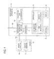
- Fig. 1 is a functional block diagram showing the configuration of a biological information monitoring apparatus 10 (hereinafter, referred to simply as the monitoring apparatus) of a first embodiment of the presently disclosed subject matter.
- the monitoring apparatus 10 includes a measurer 11, a measurement/calibration switcher 12, a controller 13, a display 14, and a storage 15.
- a plurality of kinds of signals relating to biological information which is acquired through various sensors 21 (including electrodes, a cuff, and the like) attached to the subject 20 are supplied to the measurer 11 directly or through a network.
- biological information of the subject are the pulse rate, an electrocardiogram, the blood pressure, the oxygen saturation, etc.
- the measurer 11 obtains measurement values of various kinds of biological information based on the supplied signals.
- the measurement/calibration switcher 12 includes a related-art valve device (not shown) which selectively causes one of a respiratory gas introducing passage 12a and an atmosphere opening passage 12b to communicate with a measurement gas passage 12c.
- the respiratory gas introducing passage 12a is connected an airway adaptor 22 which is attached to the mouth or nose of the subject 20.
- One end of the atmosphere opening passage 12b is opened in the atmosphere.
- the valve device of the measurement/calibration switcher 12 normally causes the respiratory gas introducing passage 12a to communicate with the measurement gas passage 12c.
- the respiratory gas of the subject 20 is introduced into the measurer 11 through the respiratory gas introducing passage 12a and the measurement gas passage 12c.
- the measurer 11 includes various related-art gas sensors (not shown), and is configured so as to measure the concentrations of specific gasses contained in the respiratory gas of the subject.
- the measurer 11 acquires measurement values of the concentrations of specific gasses, i.e., carbon dioxide (CO 2 ), oxygen (O 2 ), laughing gas (N 2 O), and isoflurane (ISO) which is a volatile anesthetic agent.
- the controller 13 is communicably connected to the measurer 11, and receives measurements values which are acquired by the measurer 11 based on the inputs from the various sensors 21, and measurement values of the concentrations of the various gasses which are acquired from the respiratory gas of the subject.
- the display 14 is a displaying device which is disposed in the front surface of the apparatus, and communicably connected to the controller 13.
- the controller 13 causes the various measurement values which are received through the measurer 11, to be displayed in real time on the display 14.
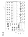
- Fig. 2 is a view showing an example of a screen displayed on the display 14. Based on the measurement values which are supplied from the measurer 11 to the controller 13, the various kinds of biological information are displayed in the form of a waveform or numerals.
- an area for displaying the measurement values of the concentrations of carbon dioxide, oxygen, laughing gas, and isoflurane which are contained in the expired gas of the subject 20 is disposed.
- the measurement value of the concentration of carbon dioxide is displayed in a first concentration display region 14a
- that of oxygen is displayed in a second concentration display region 14b
- the measurement values of the concentrations of laughing gas and isoflurane are displayed in a third concentration display region 14c.
- the accuracies of the gas sensors provided in the measurer 11 are varied over time or depending on the surrounding environment. In order to supply correct measurement values to the controller 13, it is necessary to calibrate the gas sensors at an adequate timing.
- the controller 13 functions as the calibration controller in the presently disclosed subject matter, and is configured so that, when predetermined conditions are satisfied, it is automatically shifted to a calibration mode, and performs a calibration process on the gas sensors.
- the calibration process for the gas sensors is performed immediately after activation of the monitoring apparatus 10, and at a timing when the elapsed time from the previous calibration process exceeds a predetermined value.
- the controller 13 functions as a time measurer to perform time measurement, and it is determined that the elapsed time from the previous calibration reaches the predetermined value.
- the controller 13 is communicably connected to the measurement/calibration switcher 12.
- the controller 13 controls the valve device of the measurement/calibration switcher 12 so as to cause the atmosphere opening passage 12b to communicate with the measurement gas passage 12c.
- the atmosphere is introduced into the measurer 11 through the atmosphere opening passage 12b and the measurement gas passage 12c, and the gas sensors are calibrated based on the composition of the atmosphere.
- the calibration process is well known, and therefore its detailed description is omitted.
- the respiratory gas of the subject 20 is not introduced into the measurer 11 through the respiratory gas introducing passage 12a. Therefore, the measurer 11 cannot acquire measurement values of the concentrations of the specific gasses contained in the expired gas of the subject 20.
- the second concentration display region 14b and the third concentration display region 14c are set to the measurement value non-displayed state where "---" is displayed.
- the controller 13 which functions as the time measurer acquires the remaining time before the calibration process for the gas sensors is ended.
- the calibration process which is to be performed after activation of the apparatus requires 60 seconds, and those which are to be periodically executed after each elapse of a predetermined time (for example, each elapse of 1 hour after activation) require 20 second, for example, two predetermined values which indicate the required times for the calibration process, respectively, i.e., 60 seconds and 20 seconds are stored in the storage 15.
- the controller 13 selects one of the predetermined values, and reads out it.
- the controller 13 which functions as the time measurer starts the time measuring process for the predetermined value that is read out from the storage 15.
- the process of measuring the time or 60 seconds which is the predetermined value read out from the storage 15 is started.
- the remaining time before the calibration process is ended is acquired by direct subtraction of the read out predetermined value, or by subtracting the measured time from the read out predetermined value.
- the controller 13 also functions as the display controller in the presently disclosed subject matter, and causes an index indicating the acquired remaining time to be displayed on the display 14.
- a message which is an index, and which indicates the remaining time is displayed in place of the display of "---" showing the state where the measurement of the concentration of carbon dioxide is disabled.
- the example of Fig. 3 shows a state where 30 seconds have elapsed after starting of the calibration process which is performed after activation of the monitoring apparatus 10, and a message 30 of "30 seconds remain" is displayed in the first concentration display region 14a.
- the observer monitoring the biological information can view the remaining time before the calibration process is ended. Even when the shifting to the calibration mode is unexpected to the observer monitoring the biological information, therefore, the operator can know the remaining time, and hence stress during the waiting state can be largely relieved. When the remaining time which is known by the observer is allocated for another work, or like, the working efficiency of nursing care or surgery can be improved.
- the controller 13 functioning as the time measurer selects one of a plurality of predetermined values which indicate required times for the calibration process, respectively, from the storage 15, and, based on the selected predetermined value, acquires the remaining time. Therefore, it is possible to provide a display mode in which stress can be relieved while suppressing the calculation load of the controller 13.
- the controller 13 is an arithmetic processing circuit which is configured by including an arithmetic device such as a CPU.
- the functions as the above-described calibration controller, time measurer, and display controller can be realized by the operation of hardware such as circuit devices, that of software such as programs stored in the arithmetic device, or a combination of these operations.
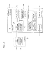
- a monitoring apparatus 10A of a second embodiment of the presently disclosed subject matter will be described with reference to Fig. 4 .
- Components which are identical with or equivalent to those of the monitoring apparatus 10 of the first embodiment are denoted by the same reference numerals, and duplicated description is omitted.
- the monitoring apparatus 10A of the embodiment includes a measurer 11A.
- the measurer 11A calculates the cardiac output based on an electrocardiogram (ECG) and pulse wave which are biological information measured from the subject 20.
- ECG electrocardiogram
- pulse wave which are biological information measured from the subject 20.
- the measurer 11A further includes a calculator 11c.
- the calculator 11c obtains by calculation the cardiac output of the subject 20 by, for example, the technique disclosed in Japanese Patent No. 4,742,644 . It is assumed that "measurement value" in the presently disclosed subject matter includes a value which is obtained by calculation based on biological information in this way.
- the calculator 11c In order to obtain the cardiac output, the calculator 11c requires information (for details, see JP-A-2010-246801 ) of the subject, and an ECG signal and pulse wave signal which are stably obtained for several minutes. Therefore, the calculation result (measurement value) of the cardiac output cannot be immediately sent to the controller 13, and hence a calibration process for several minutes is necessary for obtaining the average value of the cardiac output.
- the controller 13 functions as the calibration controller, the calibration process is performed.
- a measurement/calibration switcher 12A transmits either one of a calculation result (measurement value) of the cardiac output which is obtained as a result of calculation, and a signal indicating that the measurer 11A is performing a calculation process, to the controller 13 in accordance with the operation status of the calculator 11c.
- the controller 13 Upon receiving the signal indicating that the measurer 11A is performing a calculation process, the controller 13 which functions as the time measurer in the presently disclosed subject matter acquires the remaining time before the calibration process performed by the measurer 11A is ended (i.e., the time elapsing before the state where the calculation result can display is attained) in a similar manner as the first embodiment.
- the controller 13 which functions as the display controller in the presently disclosed subject matter causes the index indicating the acquired remaining time to be displayed on the display 14 in a similar manner as the first embodiment.
- the index which is displayed on the display 14 by the controller 13 functioning as the display controller, and which indicates the remaining time before the calibration process is ended is not limited to the above-described one, and may be displayed by using adequate characters, symbol, graph, chart, or the like from which the remaining time can be known.
- a progress bar 40 which visualizes the progress of the process may be used as the index.
- the controller 13 functioning as the time measurer obtains the rate of the elapsed time from the calibration process with respect to the predetermined value which is read out from the storage 15, and which indicates the required time for the calibration process, and the controller 13 functioning as the display controller changes the length of the progress bar 40 in accordance with the obtained rate.
- the observer monitoring a biological signal can know the progress situation (the amount of the remaining time) of the calibration process by means of viewing, and stress during the waiting state can be relieved.
- both the message 30 including numerals and the progress bar 40 may be used as the index.
- a dedicated display region 14d for displaying the index indicating the remaining time before the calibration process is ended is displayed in place of the first to third concentration display regions 14a to 14c where the measurement non-displayed state is set.
- the state where 2 seconds have elapsed after the measurement of 20 seconds read out as the predetermined value from the storage 15 is started as a result that the elapsed time from the previous calibration reaches the predetermined value is exemplarily shown.
- the storage 15 stores information indicating relationships between the predetermined conditions and the required calibration time in the form of a table or a function, and the controller 13 functioning as the time measurer calculates or acquires the remaining time before the calibration process is ended, based on the information.
- conditions such as the elapsed time from activation of the monitoring apparatus 10, the current time, the temperature in the apparatus, the atmospheric pressure, an input of an instruction for executing the calibration process by the operator, and stabilization of a signal relating to the biological information may set as the predetermined conditions. According to the configuration, even in a situation where the required time is different depending on the predetermined conditions, the remaining time can be correctly acquired.
- the time measurer provided in the controller 13, an internal timer (not shown), or the like is used, and, with respect to the temperature in the apparatus and the atmospheric pressure, sensors which can measure these parameters are disposed, whereby it is enabled to determine whether the predetermined conditions are satisfied or not.
- the biological information which relates to the respiration of the subject 20, and which is measured by the measurer 11 of the monitoring apparatus 10 of the first embodiment is not limited to the above-described concentrations of carbon dioxide, oxygen, laughing gas, and isoflurane.
- Another example of the volatile anesthetic agent which is to be measured is at least one of enflurane, sevoflurane, halothane, and desfluran.
- a configuration where the respiratory volume and the airway pressure are measured as biological information may be employed.
- a configuration where, as indicated by the broken line in Fig. 1 , a calibration gas passage 12d connected to a calibration gas accommodator 16 is disposed in place of or in addition to the atmosphere opening passage 12b may be employed.
- An adequate gas which is necessary for the calibration process is filled in the calibration gas accommodator 16.
- the controller 13 functioning as the calibration controller controls the valve device of the measurement/calibration switcher 12 so as to cause the calibration gas passage 12d to communicate with the measurement gas passage 12c.
- the calibration gas filled in the calibration gas accommodator 16 is introduced into the measurer 11 through the calibration gas passage 12d and the measurement gas passage 12c, and the gas sensors are calibrated based on the composition of the calibration gas.
- a configuration where a cylinder in which a calibration gas of known concentration is filled is connected to the atmosphere opening passage 12b may be employed.
- the controller 13 functioning as the calibration controller controls the valve device so as to cause the atmosphere opening passage 12b to communicate with the measurement gas passage 12c.
- the calibration gas filled in the cylinder is introduced into the measurer 11 through the atmosphere opening passage 12b and the measurement gas passage 12c.
- the biological information of the subject 20 which is to be measured by the measurer 11A of the monitoring apparatus 10A of the second embodiment is not limited to an ECG and the pulse wave.
- the biological information may include information relating to the blood pressure, such as the pulse pressure, or a configuration where the cardiac output is obtained by using at least two of the kinds of information may be employed.
- a configuration may be employed where the function as the time measurer is realized by at least one of the calculator 11c and the measurement/calibration switcher 12A in place of or in addition to the controller 13.
- the display 14 is not always necessary to be disposed as a part of the monitoring apparatus 10.
- a configuration where a displaying device which is disposed outside the monitoring apparatus 10, and which is communicably connected to the controller 13 functions as the display 14 may be employed.
- the storage 15 is not always necessary to be disposed separately from the controller 13, and may be configured as a part of a memory of the processing circuit constituting the controller 13.
Landscapes
- Health & Medical Sciences (AREA)
- Life Sciences & Earth Sciences (AREA)
- Engineering & Computer Science (AREA)
- Biomedical Technology (AREA)
- Physics & Mathematics (AREA)
- General Health & Medical Sciences (AREA)
- Public Health (AREA)
- Medical Informatics (AREA)
- Molecular Biology (AREA)
- Pathology (AREA)
- Heart & Thoracic Surgery (AREA)
- Surgery (AREA)
- Animal Behavior & Ethology (AREA)
- Biophysics (AREA)
- Veterinary Medicine (AREA)
- Physiology (AREA)
- Business, Economics & Management (AREA)
- General Business, Economics & Management (AREA)
- Chemical & Material Sciences (AREA)
- Computer Vision & Pattern Recognition (AREA)
- Signal Processing (AREA)
- Psychiatry (AREA)
- Artificial Intelligence (AREA)
- Primary Health Care (AREA)
- Pulmonology (AREA)
- Epidemiology (AREA)
- Optics & Photonics (AREA)
- Hematology (AREA)
- Urology & Nephrology (AREA)
- Food Science & Technology (AREA)
- Medicinal Chemistry (AREA)
- Analytical Chemistry (AREA)
- Biochemistry (AREA)
- General Physics & Mathematics (AREA)
- Immunology (AREA)
- Measuring And Recording Apparatus For Diagnosis (AREA)
Abstract
Description
- This application is based upon and claims the benefit of priority from prior Japanese patent application No. 2012-092790, filed on April 16, 2012, the entire contents of which are incorporated herein by reference.
- The presently disclosed subject matter relates to a biological information monitoring apparatus which measures biological information of the subject, and which includes a display that displays the measurement value of the biological information.
- As an apparatus of this kind, there is an apparatus in which the concentration of a predetermined gas (carbon dioxide, oxygen, a volatile anesthetic agent, or the like) contained in the expired gas of the subject is measured as biological information by a sensor, and the measurement value is displayed on a display (for example, see
JP-T-2010-508523 JP-A-2000-245711 - In a sensor, the measurement accuracy may be sometimes lowered over time by various causes, and therefore calibration must be performed at an adequate timing. In an apparatus of this kind, when a given requirement is satisfied (for example, in activation of the apparatus, or elapse of a prescribed time period from a previous calibration process), the operation mode is automatically shifted to a mode in which a calibration process is performed. During a period when a calibration process is performed, biological information cannot be measured, and therefore the portion in which the biological information is to be displayed is set to a state where a measurement value is not displayed (for example, "---" is displayed) (hereinafter, the state is referred to as the measurement value non-displayed state).
- From the standpoint of the observer monitoring biological information, it is often that the shifting to the calibration mode cannot be expected. Furthermore, the time period required for calibration is different in each case. Therefore, waiting for the end of the calibration process in which the end of the process is not known, and which is performed in the state measurement value non-displayed state causes the observer to have serious stress. In the case where such a monitoring apparatus is used for monitoring the condition of the patient under surgery, moreover, waiting for the end of the calibration process causes the working efficiency of the surgery personnel to be lowered.
- The presently disclosed subject matter may provide a biological information monitoring apparatus which can relieve the stress that, during shifting to the calibration mode, is applied to the observer monitoring biological information, and avoid lowering of the working efficiency.
- The biological information monitoring apparatus may comprise: a measurer which is configured to measure biological information of a subject; a display on which a measurement value of the biological information measured by the measurer is displayed; a calibration controller which, when a predetermined condition is satisfied, is configured to perform a calibration process on the measurer; a time measurer which is configured to acquire a remaining time before the calibration process is ended; and a display controller which is configured to cause an index indicating the remaining time to be displayed on the display.
- The index may be at least one of a numeral and a progress bar.
- Based on the predetermined condition, the time measurer may select one of a plurality of predetermined values which indicate times required for the calibration process, respectively, and, based on the selected one of the plurality of predetermined values, acquire the remaining time.
- Based on information indicating a relationship between the predetermined condition and a time required for the calibration process, the time measurer may calculate or acquire the remaining time.
- The biological information may include at least one of a concentration of a predetermined gas contained in an expired gas of the subject, a concentration of an anesthetic agent contained in an expired gas of the subject, a respiratory volume, and an airway pressure.
- The biological information may include at least two or more of an electrocardiogram, a pulse wave, and a blood pressure, and the measurer may include a calculator which is configured to calculate a cardiac output of the subject, based on the at least two or more biological information.
- The predetermined condition may relate to at least one of an elapsed time from a previous calibration process, an elapsed time from activation of the biological information monitoring apparatus, a current time, a temperature in the biological information monitoring apparatus, an atmospheric pressure, an input of an instruction by an operator, and stabilization of a signal relating to the biological information.
-
-
Fig. 1 is a functional block diagram showing the configuration of a monitoring apparatus of a first embodiment of the presently disclosed subject matter. -
Fig. 2 is a view showing an example of a screen displayed on a display of the monitoring apparatus ofFig. 1 . -
Fig. 3 is a view showing another example of the screen displayed on the display of the monitoring apparatus ofFig. 1 . -
Fig. 4 is a functional block diagram showing the configuration of a monitoring apparatus of a second embodiment of the presently disclosed subject matter. -
Fig. 5 is a view showing a further example of the screen displayed on the display of the monitoring apparatus ofFig. 1 . -
Fig. 6 is a view showing a still further example of the screen displayed on the display of the monitoring apparatus ofFig. 1 . - Hereinafter, embodiments of the presently disclosed subject matter will be described in detail with reference to the accompanying drawings.
-
Fig. 1 is a functional block diagram showing the configuration of a biological information monitoring apparatus 10 (hereinafter, referred to simply as the monitoring apparatus) of a first embodiment of the presently disclosed subject matter. Themonitoring apparatus 10 includes ameasurer 11, a measurement/calibration switcher 12, acontroller 13, adisplay 14, and astorage 15. - A plurality of kinds of signals relating to biological information which is acquired through various sensors 21 (including electrodes, a cuff, and the like) attached to the
subject 20 are supplied to themeasurer 11 directly or through a network. Examples of biological information of the subject are the pulse rate, an electrocardiogram, the blood pressure, the oxygen saturation, etc. Themeasurer 11 obtains measurement values of various kinds of biological information based on the supplied signals. - The measurement/
calibration switcher 12 includes a related-art valve device (not shown) which selectively causes one of a respiratorygas introducing passage 12a and an atmosphere openingpassage 12b to communicate with ameasurement gas passage 12c. The respiratorygas introducing passage 12a is connected anairway adaptor 22 which is attached to the mouth or nose of thesubject 20. One end of theatmosphere opening passage 12b is opened in the atmosphere. - The valve device of the measurement/
calibration switcher 12 normally causes the respiratorygas introducing passage 12a to communicate with themeasurement gas passage 12c. The respiratory gas of thesubject 20 is introduced into themeasurer 11 through the respiratorygas introducing passage 12a and themeasurement gas passage 12c. - The
measurer 11 includes various related-art gas sensors (not shown), and is configured so as to measure the concentrations of specific gasses contained in the respiratory gas of the subject. In the embodiment, themeasurer 11 acquires measurement values of the concentrations of specific gasses, i.e., carbon dioxide (CO2), oxygen (O2), laughing gas (N2O), and isoflurane (ISO) which is a volatile anesthetic agent. - The
controller 13 is communicably connected to themeasurer 11, and receives measurements values which are acquired by themeasurer 11 based on the inputs from thevarious sensors 21, and measurement values of the concentrations of the various gasses which are acquired from the respiratory gas of the subject. - The
display 14 is a displaying device which is disposed in the front surface of the apparatus, and communicably connected to thecontroller 13. Thecontroller 13 causes the various measurement values which are received through themeasurer 11, to be displayed in real time on thedisplay 14. -
Fig. 2 is a view showing an example of a screen displayed on thedisplay 14. Based on the measurement values which are supplied from themeasurer 11 to thecontroller 13, the various kinds of biological information are displayed in the form of a waveform or numerals. In the lower left portion of the screen, an area for displaying the measurement values of the concentrations of carbon dioxide, oxygen, laughing gas, and isoflurane which are contained in the expired gas of thesubject 20 is disposed. Specifically, the measurement value of the concentration of carbon dioxide is displayed in a firstconcentration display region 14a, that of oxygen is displayed in a secondconcentration display region 14b, and the measurement values of the concentrations of laughing gas and isoflurane are displayed in a thirdconcentration display region 14c. - The accuracies of the gas sensors provided in the
measurer 11 are varied over time or depending on the surrounding environment. In order to supply correct measurement values to thecontroller 13, it is necessary to calibrate the gas sensors at an adequate timing. Thecontroller 13 functions as the calibration controller in the presently disclosed subject matter, and is configured so that, when predetermined conditions are satisfied, it is automatically shifted to a calibration mode, and performs a calibration process on the gas sensors. - Specifically, the calibration process for the gas sensors is performed immediately after activation of the
monitoring apparatus 10, and at a timing when the elapsed time from the previous calibration process exceeds a predetermined value. In this case, thecontroller 13 functions as a time measurer to perform time measurement, and it is determined that the elapsed time from the previous calibration reaches the predetermined value. - As shown in
Fig. 1 , thecontroller 13 is communicably connected to the measurement/calibration switcher 12. When the predetermined conditions are satisfied, thecontroller 13 controls the valve device of the measurement/calibration switcher 12 so as to cause theatmosphere opening passage 12b to communicate with themeasurement gas passage 12c. As a result, the atmosphere is introduced into themeasurer 11 through theatmosphere opening passage 12b and themeasurement gas passage 12c, and the gas sensors are calibrated based on the composition of the atmosphere. The calibration process is well known, and therefore its detailed description is omitted. - During execution of the calibration process, the respiratory gas of the
subject 20 is not introduced into themeasurer 11 through the respiratorygas introducing passage 12a. Therefore, themeasurer 11 cannot acquire measurement values of the concentrations of the specific gasses contained in the expired gas of thesubject 20. In this case, as shown inFig. 3 , the secondconcentration display region 14b and the thirdconcentration display region 14c are set to the measurement value non-displayed state where "---" is displayed. - By contrast, the
controller 13 which functions as the time measurer acquires the remaining time before the calibration process for the gas sensors is ended. In the case where the calibration process which is to be performed after activation of the apparatus requires 60 seconds, and those which are to be periodically executed after each elapse of a predetermined time (for example, each elapse of 1 hour after activation) require 20 second, for example, two predetermined values which indicate the required times for the calibration process, respectively, i.e., 60 seconds and 20 seconds are stored in thestorage 15. In accordance with the conditions which are satisfied at the timing when the calibration process is to be performed, thecontroller 13 selects one of the predetermined values, and reads out it. - The
controller 13 which functions as the time measurer starts the time measuring process for the predetermined value that is read out from thestorage 15. In the calibration process which is performed immediately after activation of the apparatus, for example, the process of measuring the time or 60 seconds which is the predetermined value read out from thestorage 15 is started. The remaining time before the calibration process is ended is acquired by direct subtraction of the read out predetermined value, or by subtracting the measured time from the read out predetermined value. - The
controller 13 also functions as the display controller in the presently disclosed subject matter, and causes an index indicating the acquired remaining time to be displayed on thedisplay 14. In the firstconcentration display region 14a, as shown inFig. 3 , a message which is an index, and which indicates the remaining time is displayed in place of the display of "---" showing the state where the measurement of the concentration of carbon dioxide is disabled. The example ofFig. 3 shows a state where 30 seconds have elapsed after starting of the calibration process which is performed after activation of themonitoring apparatus 10, and amessage 30 of "30 seconds remain" is displayed in the firstconcentration display region 14a. - According to the configuration of the embodiment, the observer monitoring the biological information can view the remaining time before the calibration process is ended. Even when the shifting to the calibration mode is unexpected to the observer monitoring the biological information, therefore, the operator can know the remaining time, and hence stress during the waiting state can be largely relieved. When the remaining time which is known by the observer is allocated for another work, or like, the working efficiency of nursing care or surgery can be improved.
- Based on predetermined conditions, the
controller 13 functioning as the time measurer selects one of a plurality of predetermined values which indicate required times for the calibration process, respectively, from thestorage 15, and, based on the selected predetermined value, acquires the remaining time. Therefore, it is possible to provide a display mode in which stress can be relieved while suppressing the calculation load of thecontroller 13. - The
controller 13 is an arithmetic processing circuit which is configured by including an arithmetic device such as a CPU. The functions as the above-described calibration controller, time measurer, and display controller can be realized by the operation of hardware such as circuit devices, that of software such as programs stored in the arithmetic device, or a combination of these operations. - Next, a
monitoring apparatus 10A of a second embodiment of the presently disclosed subject matter will be described with reference toFig. 4 . Components which are identical with or equivalent to those of themonitoring apparatus 10 of the first embodiment are denoted by the same reference numerals, and duplicated description is omitted. - The
monitoring apparatus 10A of the embodiment includes ameasurer 11A. Themeasurer 11A calculates the cardiac output based on an electrocardiogram (ECG) and pulse wave which are biological information measured from the subject 20. - Signals which relate to the electrocardiogram and the pulse wave, respectively, and which are acquired through an
ECG sensor 21a andpulse wave sensor 21b that are attached to the subject 20 are supplied to anECG measurer 11a andpulse wave measurer 11b in themeasurer 11A. Themeasurer 11A further includes acalculator 11c. Thecalculator 11c obtains by calculation the cardiac output of the subject 20 by, for example, the technique disclosed in Japanese Patent No.4,742,644 - In order to obtain the cardiac output, the
calculator 11c requires information (for details, seeJP-A-2010-246801 controller 13, and hence a calibration process for several minutes is necessary for obtaining the average value of the cardiac output. When thecontroller 13 functions as the calibration controller, the calibration process is performed. - The calibration time depends also on the measurement environment, and therefore is hardly identified in an unambiguous manner. This causes the observer to have serious stress. In the embodiment, therefore, a measurement/
calibration switcher 12A transmits either one of a calculation result (measurement value) of the cardiac output which is obtained as a result of calculation, and a signal indicating that themeasurer 11A is performing a calculation process, to thecontroller 13 in accordance with the operation status of thecalculator 11c. - Upon receiving the signal indicating that the
measurer 11A is performing a calculation process, thecontroller 13 which functions as the time measurer in the presently disclosed subject matter acquires the remaining time before the calibration process performed by themeasurer 11A is ended (i.e., the time elapsing before the state where the calculation result can display is attained) in a similar manner as the first embodiment. Thecontroller 13 which functions as the display controller in the presently disclosed subject matter causes the index indicating the acquired remaining time to be displayed on thedisplay 14 in a similar manner as the first embodiment. - The embodiments have been described in order to facilitate understanding of the presently disclosed subject matter, and are not intended to limit the presently disclosed subject matter. It is a matter of course that the presently disclosed subject matter may be changed or improved without departing the spirit thereof, and includes equivalents thereof.
- The index which is displayed on the
display 14 by thecontroller 13 functioning as the display controller, and which indicates the remaining time before the calibration process is ended is not limited to the above-described one, and may be displayed by using adequate characters, symbol, graph, chart, or the like from which the remaining time can be known. - As shown in
Fig. 5 , for example, aprogress bar 40 which visualizes the progress of the process may be used as the index. Thecontroller 13 functioning as the time measurer obtains the rate of the elapsed time from the calibration process with respect to the predetermined value which is read out from thestorage 15, and which indicates the required time for the calibration process, and thecontroller 13 functioning as the display controller changes the length of theprogress bar 40 in accordance with the obtained rate. According to the configuration, the observer monitoring a biological signal can know the progress situation (the amount of the remaining time) of the calibration process by means of viewing, and stress during the waiting state can be relieved. - As shown in
Fig. 6 , both themessage 30 including numerals and theprogress bar 40 may be used as the index. In this example, adedicated display region 14d for displaying the index indicating the remaining time before the calibration process is ended is displayed in place of the first to thirdconcentration display regions 14a to 14c where the measurement non-displayed state is set. In the figure, the state where 2 seconds have elapsed after the measurement of 20 seconds read out as the predetermined value from thestorage 15 is started as a result that the elapsed time from the previous calibration reaches the predetermined value is exemplarily shown. - In place of or in addition to the configuration where the predetermined value indicating the required calibration time is previously stored in the
storage 15, a configuration may be employed where thestorage 15 stores information indicating relationships between the predetermined conditions and the required calibration time in the form of a table or a function, and thecontroller 13 functioning as the time measurer calculates or acquires the remaining time before the calibration process is ended, based on the information. - In place of or in addition to the conditions where the
monitoring apparatus 10 has been activated, and where the elapsed time from the previous calibration process reaches the predetermined value, conditions such as the elapsed time from activation of themonitoring apparatus 10, the current time, the temperature in the apparatus, the atmospheric pressure, an input of an instruction for executing the calibration process by the operator, and stabilization of a signal relating to the biological information may set as the predetermined conditions. According to the configuration, even in a situation where the required time is different depending on the predetermined conditions, the remaining time can be correctly acquired. - With respect to the elapsed time and the current time, the time measurer provided in the
controller 13, an internal timer (not shown), or the like is used, and, with respect to the temperature in the apparatus and the atmospheric pressure, sensors which can measure these parameters are disposed, whereby it is enabled to determine whether the predetermined conditions are satisfied or not. - The biological information which relates to the respiration of the subject 20, and which is measured by the
measurer 11 of themonitoring apparatus 10 of the first embodiment is not limited to the above-described concentrations of carbon dioxide, oxygen, laughing gas, and isoflurane. Another example of the volatile anesthetic agent which is to be measured is at least one of enflurane, sevoflurane, halothane, and desfluran. Alternatively, a configuration where the respiratory volume and the airway pressure are measured as biological information may be employed. - A configuration where, as indicated by the broken line in
Fig. 1 , acalibration gas passage 12d connected to acalibration gas accommodator 16 is disposed in place of or in addition to theatmosphere opening passage 12b may be employed. An adequate gas which is necessary for the calibration process is filled in thecalibration gas accommodator 16. When the predetermined conditions are satisfied, thecontroller 13 functioning as the calibration controller controls the valve device of the measurement/calibration switcher 12 so as to cause thecalibration gas passage 12d to communicate with themeasurement gas passage 12c. The calibration gas filled in thecalibration gas accommodator 16 is introduced into themeasurer 11 through thecalibration gas passage 12d and themeasurement gas passage 12c, and the gas sensors are calibrated based on the composition of the calibration gas. - Alternatively, a configuration where a cylinder in which a calibration gas of known concentration is filled is connected to the
atmosphere opening passage 12b may be employed. In this case, thecontroller 13 functioning as the calibration controller controls the valve device so as to cause theatmosphere opening passage 12b to communicate with themeasurement gas passage 12c. The calibration gas filled in the cylinder is introduced into themeasurer 11 through theatmosphere opening passage 12b and themeasurement gas passage 12c. - The biological information of the subject 20 which is to be measured by the
measurer 11A of themonitoring apparatus 10A of the second embodiment is not limited to an ECG and the pulse wave. As required, the biological information may include information relating to the blood pressure, such as the pulse pressure, or a configuration where the cardiac output is obtained by using at least two of the kinds of information may be employed. - In the
monitoring apparatus 10A of the second embodiment, a configuration may be employed where the function as the time measurer is realized by at least one of thecalculator 11c and the measurement/calibration switcher 12A in place of or in addition to thecontroller 13. - The
display 14 is not always necessary to be disposed as a part of themonitoring apparatus 10. A configuration where a displaying device which is disposed outside themonitoring apparatus 10, and which is communicably connected to thecontroller 13 functions as thedisplay 14 may be employed. - The
storage 15 is not always necessary to be disposed separately from thecontroller 13, and may be configured as a part of a memory of the processing circuit constituting thecontroller 13.
Claims (7)
- A biological information monitoring apparatus comprising:a measurer which is configured to measure biological information of a subject;a display on which a measurement value of the biological information measured by the measurer is displayed;a calibration controller which, when a predetermined condition is satisfied, is configured to perform a calibration process on the measurer;a time measurer which is configured to acquire a remaining time before the calibration process is ended; anda display controller which is configured to cause an index indicating the remaining time to be displayed on the display.
- The biological information monitoring apparatus according to claim 1, wherein the index is at least one of a numeral and a progress bar.
- The biological information monitoring apparatus according to claim 1, wherein, based on the predetermined condition, the time measurer selects one of a plurality of predetermined values which indicate times required for the calibration process, respectively, and, based on the selected one of the plurality of predetermined values, acquires the remaining time.
- The biological information monitoring apparatus according to claim 1, wherein, based on information indicating a relationship between the predetermined condition and a time required for the calibration process, the time measurer calculates or acquires the remaining time.
- The biological information monitoring apparatus according to claim 1, wherein the biological information includes at least one of a concentration of a predetermined gas contained in an expired gas of the subject, a concentration of an anesthetic agent contained in an expired gas of the subject, a respiratory volume, and an airway pressure.
- The biological information monitoring apparatus according to claim 1, wherein
the biological information includes at least two or more of an electrocardiogram, a pulse wave, and a blood pressure, and
the measurer includes a calculator which is configured to calculate a cardiac output of the subject, based on the at least two or more biological information. - The biological information monitoring apparatus according to claim 1, wherein the predetermined condition relates to at least one of an elapsed time from a previous calibration process, an elapsed time from activation of the biological information monitoring apparatus, a current time, a temperature in the biological information monitoring apparatus, an atmospheric pressure, an input of an instruction by an operator, and stabilization of a signal relating to the biological information.
Applications Claiming Priority (1)
| Application Number | Priority Date | Filing Date | Title |
|---|---|---|---|
| JP2012092790A JP5927013B2 (en) | 2012-04-16 | 2012-04-16 | Biological information monitor device |
Publications (1)
| Publication Number | Publication Date |
|---|---|
| EP2653097A1 true EP2653097A1 (en) | 2013-10-23 |
Family
ID=48143458
Family Applications (1)
| Application Number | Title | Priority Date | Filing Date |
|---|---|---|---|
| EP13163712.6A Withdrawn EP2653097A1 (en) | 2012-04-16 | 2013-04-15 | Biological information monitoring apparatus |
Country Status (3)
| Country | Link |
|---|---|
| US (1) | US10058286B2 (en) |
| EP (1) | EP2653097A1 (en) |
| JP (1) | JP5927013B2 (en) |
Families Citing this family (7)
| Publication number | Priority date | Publication date | Assignee | Title |
|---|---|---|---|---|
| JP6422653B2 (en) * | 2014-01-24 | 2018-11-14 | 日本光電工業株式会社 | Monitoring device |
| DE102016218009B4 (en) * | 2016-09-20 | 2023-08-31 | Siemens Healthcare Gmbh | A method for outputting output information during a medical imaging examination, the output information indicating a remaining examination time of the medical imaging examination for a patient |
| CN111093746B (en) * | 2017-10-20 | 2023-02-28 | 深圳迈瑞生物医疗电子股份有限公司 | Anesthesia machine, oxygen battery calibration system and calibration method thereof |
| US11510579B2 (en) | 2018-01-19 | 2022-11-29 | Samsung Electronics Co., Ltd. | Apparatus and method for determining calibration timing for blood pressure measurement in electronic device |
| JP7141681B2 (en) | 2018-01-29 | 2022-09-26 | 株式会社Agama-X | Information processing device, information processing system and program |
| JP7141680B2 (en) * | 2018-01-29 | 2022-09-26 | 株式会社Agama-X | Information processing device, information processing system and program |
| JP7105530B2 (en) * | 2019-04-24 | 2022-07-25 | 株式会社日立ハイテク | Automated analyzers and maintenance guide methods for automated analyzers |
Citations (9)
| Publication number | Priority date | Publication date | Assignee | Title |
|---|---|---|---|---|
| US5899855A (en) * | 1992-11-17 | 1999-05-04 | Health Hero Network, Inc. | Modular microprocessor-based health monitoring system |
| JP2000245711A (en) | 1999-02-25 | 2000-09-12 | Instrumentarium Oy | Method for compensating measured concentration value and use thereof |
| US20070034792A1 (en) * | 2005-08-12 | 2007-02-15 | Shenzhen Mindray Bio-Medical Electronics Co., Ltd. | Method and apparatus for detecting gas concentration with infrared absorption characteristics |
| US20090326335A1 (en) * | 2008-06-30 | 2009-12-31 | Baker Clark R | Pulse Oximeter With Wait-Time Indication |
| JP2010508523A (en) | 2006-10-31 | 2010-03-18 | アールアイシー・インベストメンツ・エルエルシー | System and method for calibrating determination of partial pressure of one or more gaseous analytes |
| CN101176663B (en) * | 2007-12-06 | 2010-10-27 | 山东大学 | Non-invasive cardiac output detection method and device based on pulse wave |
| JP2010246801A (en) | 2009-04-17 | 2010-11-04 | Nippon Koden Corp | Blood volume measuring method, blood volume measuring apparatus and blood volume measuring program |
| WO2011026053A1 (en) * | 2009-08-31 | 2011-03-03 | Abbott Diabetes Care Inc. | Displays for a medical device |
| JP4742644B2 (en) | 2004-03-31 | 2011-08-10 | 日本光電工業株式会社 | Blood volume measuring method, measuring apparatus and biological signal monitoring apparatus |
Family Cites Families (16)
| Publication number | Priority date | Publication date | Assignee | Title |
|---|---|---|---|---|
| JPH09133646A (en) * | 1995-11-07 | 1997-05-20 | Yazaki Corp | Alcohol concentration measuring device and control method thereof |
| JP2003524149A (en) * | 1999-06-08 | 2003-08-12 | オリディオン ブレシド リミティド | Gas analyzer verification test equipment |
| CN100563547C (en) | 2001-11-01 | 2009-12-02 | 斯科特实验室公司 | User interface for sedative and analgesic delivery systems and methods |
| US6711425B1 (en) * | 2002-05-28 | 2004-03-23 | Ob Scientific, Inc. | Pulse oximeter with calibration stabilization |
| SG152019A1 (en) * | 2003-01-29 | 2009-05-29 | Healthstats Int Pte Ltd | Noninvasive blood pressure monitoring system |
| WO2005025646A2 (en) * | 2003-09-08 | 2005-03-24 | U.S. Government As Represented By The Secretary Of The Army | System and method for providing servo-controlled resuscitation |
| US7402138B2 (en) | 2004-03-31 | 2008-07-22 | Nihon Kohden Corporation | Method and apparatus for measuring blood volume, and vital sign monitor using the same |
| JP4606069B2 (en) * | 2004-06-11 | 2011-01-05 | 興和株式会社 | Ophthalmic measuring device |
| CN101547716B (en) * | 2005-11-16 | 2013-06-26 | 心肺技术公司 | Side-stream respiratory gas monitoring system and method |
| US8998809B2 (en) * | 2006-05-15 | 2015-04-07 | Cercacor Laboratories, Inc. | Systems and methods for calibrating minimally invasive and non-invasive physiological sensor devices |
| EP2150814A2 (en) * | 2007-05-10 | 2010-02-10 | Glumetrics, Inc. | Device and methods for calibrating analyte sensors |
| US20080300572A1 (en) * | 2007-06-01 | 2008-12-04 | Medtronic Minimed, Inc. | Wireless monitor for a personal medical device system |
| WO2009082318A1 (en) * | 2007-12-20 | 2009-07-02 | Aerocrine Ab | Method for testing the function of a device |
| RU2556515C2 (en) * | 2008-08-28 | 2015-07-10 | Конинклейке Филипс Электроникс, Н.В. | Method of providing data remoteness visualisation |
| GB2487882B (en) * | 2009-12-04 | 2017-03-29 | Masimo Corp | Calibration for multi-stage physiological monitors |
| US9848809B2 (en) * | 2011-04-15 | 2017-12-26 | Dexcom, Inc. | Advanced analyte sensor calibration and error detection |
-
2012
- 2012-04-16 JP JP2012092790A patent/JP5927013B2/en not_active Expired - Fee Related
-
2013
- 2013-04-15 US US13/862,974 patent/US10058286B2/en active Active
- 2013-04-15 EP EP13163712.6A patent/EP2653097A1/en not_active Withdrawn
Patent Citations (9)
| Publication number | Priority date | Publication date | Assignee | Title |
|---|---|---|---|---|
| US5899855A (en) * | 1992-11-17 | 1999-05-04 | Health Hero Network, Inc. | Modular microprocessor-based health monitoring system |
| JP2000245711A (en) | 1999-02-25 | 2000-09-12 | Instrumentarium Oy | Method for compensating measured concentration value and use thereof |
| JP4742644B2 (en) | 2004-03-31 | 2011-08-10 | 日本光電工業株式会社 | Blood volume measuring method, measuring apparatus and biological signal monitoring apparatus |
| US20070034792A1 (en) * | 2005-08-12 | 2007-02-15 | Shenzhen Mindray Bio-Medical Electronics Co., Ltd. | Method and apparatus for detecting gas concentration with infrared absorption characteristics |
| JP2010508523A (en) | 2006-10-31 | 2010-03-18 | アールアイシー・インベストメンツ・エルエルシー | System and method for calibrating determination of partial pressure of one or more gaseous analytes |
| CN101176663B (en) * | 2007-12-06 | 2010-10-27 | 山东大学 | Non-invasive cardiac output detection method and device based on pulse wave |
| US20090326335A1 (en) * | 2008-06-30 | 2009-12-31 | Baker Clark R | Pulse Oximeter With Wait-Time Indication |
| JP2010246801A (en) | 2009-04-17 | 2010-11-04 | Nippon Koden Corp | Blood volume measuring method, blood volume measuring apparatus and blood volume measuring program |
| WO2011026053A1 (en) * | 2009-08-31 | 2011-03-03 | Abbott Diabetes Care Inc. | Displays for a medical device |
Also Published As
| Publication number | Publication date |
|---|---|
| US20130274617A1 (en) | 2013-10-17 |
| JP5927013B2 (en) | 2016-05-25 |
| US10058286B2 (en) | 2018-08-28 |
| JP2013220175A (en) | 2013-10-28 |
Similar Documents
| Publication | Publication Date | Title |
|---|---|---|
| US10058286B2 (en) | Biological information monitoring apparatus | |
| US10350374B2 (en) | Ventilator system and method | |
| RU2624343C2 (en) | Device to control warning device signal limit | |
| EP1951347B1 (en) | Side-stream respiratory gas monitoring system | |
| US10022084B2 (en) | Apparatus for determining respiratory condition | |
| US20130345532A1 (en) | Medical ventilator with integrated oximeter data | |
| Luján et al. | Basic concepts for tidal volume and leakage estimation in non-invasive ventilation | |
| JP2004313795A (en) | Apparatus for monitoring gas concentration | |
| US11717247B2 (en) | Blood flow control system and methods for in-vivo imaging and other applications | |
| US20110112424A1 (en) | Determining functional residual lung capacity | |
| Newth et al. | Multiple-breath nitrogen washout techniques: including measurements with patients on ventilators | |
| CN106659436B (en) | Determination of arterial partial pressure of CO2 | |
| SE1550671A1 (en) | Method System and Software for Protective Ventilation | |
| US20140336523A1 (en) | Estimation of energy expenditure | |
| US20220008698A1 (en) | Automatic evaluation of a filling volume of an oesophageal balloon catheter | |
| WO2005058127B1 (en) | Laryngoscope with time indicating means and method for use thereof | |
| US11045105B2 (en) | Determination of cardiac output or effective pulmonary blood flow during mechanical ventilation | |
| CN105520723A (en) | Vital sign measuring device, vital sign display method and program | |
| US8858457B2 (en) | Method and device for the automatic evaluation and analysis of a capnogram and computer program for implementing the method as well as computer program product with such a computer program | |
| WO2017138580A1 (en) | Bioinformation display device | |
| EP4454688A1 (en) | Respiration monitoring method and respiration monitoring apparatus | |
| US20050288602A1 (en) | Device and method for determining respiratory quotient without measuring lung ventilation | |
| JP6140404B2 (en) | Calibration of the delay time of the breath gas analyzer | |
| EP3158926B1 (en) | Pulse wave analyzer | |
| US11636950B2 (en) | System for non-invasive examination of blood environment parameters |
Legal Events
| Date | Code | Title | Description |
|---|---|---|---|
| PUAI | Public reference made under article 153(3) epc to a published international application that has entered the european phase |
Free format text: ORIGINAL CODE: 0009012 |
|
| AK | Designated contracting states |
Kind code of ref document: A1 Designated state(s): AL AT BE BG CH CY CZ DE DK EE ES FI FR GB GR HR HU IE IS IT LI LT LU LV MC MK MT NL NO PL PT RO RS SE SI SK SM TR |
|
| AX | Request for extension of the european patent |
Extension state: BA ME |
|
| 17P | Request for examination filed |
Effective date: 20140410 |
|
| RBV | Designated contracting states (corrected) |
Designated state(s): AL AT BE BG CH CY CZ DE DK EE ES FI FR GB GR HR HU IE IS IT LI LT LU LV MC MK MT NL NO PL PT RO RS SE SI SK SM TR |
|
| STAA | Information on the status of an ep patent application or granted ep patent |
Free format text: STATUS: EXAMINATION IS IN PROGRESS |
|
| 17Q | First examination report despatched |
Effective date: 20170222 |
|
| STAA | Information on the status of an ep patent application or granted ep patent |
Free format text: STATUS: THE APPLICATION IS DEEMED TO BE WITHDRAWN |
|
| 18D | Application deemed to be withdrawn |
Effective date: 20191101 |