EP2653087A1 - Geschirrspülautomat - Google Patents
Geschirrspülautomat Download PDFInfo
- Publication number
- EP2653087A1 EP2653087A1 EP13401038.8A EP13401038A EP2653087A1 EP 2653087 A1 EP2653087 A1 EP 2653087A1 EP 13401038 A EP13401038 A EP 13401038A EP 2653087 A1 EP2653087 A1 EP 2653087A1
- Authority
- EP
- European Patent Office
- Prior art keywords
- rinsing
- housing
- dishwasher according
- lamp
- scraper
- Prior art date
- Legal status (The legal status is an assumption and is not a legal conclusion. Google has not performed a legal analysis and makes no representation as to the accuracy of the status listed.)
- Granted
Links
Images



Classifications
-
- A—HUMAN NECESSITIES
- A47—FURNITURE; DOMESTIC ARTICLES OR APPLIANCES; COFFEE MILLS; SPICE MILLS; SUCTION CLEANERS IN GENERAL
- A47L—DOMESTIC WASHING OR CLEANING; SUCTION CLEANERS IN GENERAL
- A47L15/00—Washing or rinsing machines for crockery or tableware
- A47L15/42—Details
- A47L15/4236—Arrangements to sterilize or disinfect dishes or washing liquids
- A47L15/4242—Arrangements to sterilize or disinfect dishes or washing liquids by using ultraviolet generators
-
- A—HUMAN NECESSITIES
- A47—FURNITURE; DOMESTIC ARTICLES OR APPLIANCES; COFFEE MILLS; SPICE MILLS; SUCTION CLEANERS IN GENERAL
- A47L—DOMESTIC WASHING OR CLEANING; SUCTION CLEANERS IN GENERAL
- A47L15/00—Washing or rinsing machines for crockery or tableware
- A47L15/42—Details
- A47L15/4251—Details of the casing
- A47L15/4257—Details of the loading door
Definitions
- the invention relates to an automatic dishwasher, in particular a dishwasher for use in the home, with a rinsing container providing a rinsing container, which has a closable by means of a pivotally mounted Spülraumt feed opening, and with a reservoir for the intermediate storage of rinsing liquor.
- Dishwashers of the type mentioned are well known in the art. They have a rinsing container which provides a rinsing container which, in the intended use, serves to receive items to be cleaned. To feed the washing container is a feed opening, which is closed fluid-tight by means of a pivotally mounted dish door.
- spray arms For loading of items to be cleaned with rinse liquor within the rinsing container rotatably arranged spray arms. These are supplied with rinsing fluid via a circulation pump. Depending on the configuration of the dishwasher, preferably two or three spray arms are provided.
- the rinsing fluid cached within the storage container is subject to contamination. This often results in conjunction with an odor nuisance.
- a filter in the fluidic connection between the washing container and the reservoir. It is the purpose of such a filter to filter out particles, impurities, contaminants and / or the like present in the wash liquor, before the wash liquor is transferred into the storage container for intermediate storage.
- a dishwashing machine of the type mentioned above is proposed with the invention, which is characterized by a germinating device used in the fluidic connection between washing container and reservoir, wherein the sterilizing device comprises a housing, a UV lamp arranged therein and a with the UV Lamp and the housing has cooperating scraper, wherein the scraper is slidably mounted in the housing.
- the dishwashing machine proposed by the invention has a sterilizing device.
- This sterilization device is passed by the rinsing liquor before it flows into the reservoir, whereby it comes to a sterilization of the same.
- For intermediate storage in the reservoir thus sterilized rinse liquor.
- the degerminator has a housing.
- a UV lamp is arranged in the UV lamp is preferably a UVC lamp, that is, a lamp that emits light in the ultraviolet spectrum in the wavelength range between 280 nm and 200 nm.
- the UV lamp is the heart of the sterilization device. It is in the case of the intended admission with rinsing liquor, that is turned on in the case of transfer of rinsing water from the washing container into the reservoir.
- the radiation emitted by it acts on the rinsing liquor introduced into the sterilization device, as a result of which an inactivation, that is to say the killing of bacteria, germs and / or similar biological substances, occurs.
- an inactivation that is to say the killing of bacteria, germs and / or similar biological substances
- deposits of impurities, contaminants and / or the like originating from the rinsing liquor can occur on the housing of the sterilizing device and / or on the UV lamp.
- any deposits on the UV lamp can interfere with the intended operation of the sterilization device, as in the intended use of radiation emitted by the UV lamp radiation can not fully reach the rinsing water to be sterilized.
- this is equipped with a scraper, which cooperates with the UV lamp on the one hand and the housing on the other.
- the scraper is guided displaceably in the housing, so that in the case of an intended displacement movement, in particular, it travels along the UV lamp and strips off any deposits of particles, contaminants, dirt and / or the like.
- these deposits removed by the scraper can be transported back into the washing room, from where they can be disposed of by pumping. In this case, such pumping preferably takes place during a subsequent intended program execution.
- the provided according to the invention sterilizing device is self-cleaning.
- the scraper guided in the housing of the sterilizing device ensures that deposits forming in the sterilizing device, in particular on the UV lamp, are removed, so that a return of the same into the washing container is permitted. Clogging of the sterilization device is thus prevented.
- a manual cleaning to be performed by the user is advantageously not required.
- a sterilization of the rinsing liquor to be supplied to the storage container takes place via the sterilization device provided according to the invention.
- the sterilization device For intermediate storage in the reservoir thus sterilized rinse liquor, so that the risk of microbial contamination in the reservoir and the associated risk of odor nuisance is minimized.
- the sterilizing device is backwashed, so that deposits previously formed in the sterilizing device may flow into the rinsing container, where it will then be disposed of in the course of a proper program execution.
- the scraper provided according to the invention ensures that a cleaning of the sterilization device is carried out, so that a user-side manual cleaning is not necessary.
- the sterilizing device has a cooperating with the scraper driver, which is arranged on the outside of the housing on this displaceable.
- the scraper and / or the driver on a magnet and / or the scraper or the driver are at least partially formed as a magnet.
- the driver is mechanically coupled to the Spülraume, for which purpose preferably a Bowden cable is provided.
- a pivoting movement of the Spülraume it comes so to a movement of coupled via the Bowden cable with the Spülraumc driver.
- This in turn interacts magnetically with the scraper, resulting in a result of a movement of the Spülraumc in the result a movement of the cooperating with particular UV lamp scraper comes.
- Each user-side actuation of the Spülraumt it comes with it to a movement of the scraper and thus to a removal of any deposits on the housing and / or the UV lamp of the sterilization device.
- the UV lamp is arranged according to a special feature of the invention within a hollow cylinder.
- This hollow cylinder is inserted while leaving an annular gap in the housing of the sterilization device.
- This hollow cylinder serves to protect the UV lamp and is formed from a material permeable to the radiation emitted by the UV lamp. A direct contact of the rinsing liquor with the UV lamp does not take place according to this embodiment.
- the rinsing fluid flows on the outside of the UV lamp receiving hollow cylinder along.
- the scraper is annular according to a further feature of the invention and arranged on the other hand within the annular gap space between the housing on the one hand and the hollow cylinder. Within this annular gap, the scraper can be moved in the height direction of the housing. In this case, the scraper is preferably in contact both with the inside of the housing and with the outside of the hollow cylinder. As a result, it comes with a movement of the scraper to remove any deposits that can form on the inside of the housing and / or on the outside of the hollow cylinder. During a traversing movement of the scraper this moves both on the inside of the housing and on the outside of the wooden cylinder along, as a result of which there is a Mitrymaschine tearing off any deposits located here.
- a plurality of UV lamps may be arranged.
- the radiation intensity can be increased in this way.
- the UV lamps are preferably rod-shaped and placed side by side within the hollow cylinder.
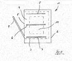
- Fig. 1 can be seen in a schematic representation of a dishwasher 1. This has a housing 2, which receives a washing compartment 4 providing a washing compartment 3. The washing container 3 is used in the intended use of the inclusion of items to be cleaned.
- the washing compartment 4 provided by the washing container 3 is accessible via a charging opening 8. This is by means of a pivotally mounted on the housing 2 Spülraumt 9 fluid-tight closed.
- spray arms are arranged within the washing container, wherein in the illustrated embodiment a total of three spray arms are provided, namely an upper spray arm 5, a central spray arm 6 and a lower spray arm. 7
- the dishwasher 1 further has a reservoir 10 for the intermediate storage of rinsing water.
- This reservoir 10 may be formed within the housing 2 or outside thereof. In the illustrated embodiment, the reservoir 10 is housed in the gap space not shown between rinsing 3 on the one hand and housing 2 on the other.
- the reservoir 10 is fluidly coupled to the washing container 3. About this fluidic connection can be removed from the rinse tank 3 rinse and fed to the reservoir 10 or transferred in the reverse direction from the reservoir 10 in the washing compartment 3.
- the storage container 10 serves for the intermediate storage of rinsing liquor.
- the rinse tank 3 is removed at the end of a designated wash cycle rinsing program and cached in the reservoir 10 until the beginning of a next wash program.
- the storage container 10 allows the intermediate storage of rinsing water, whereby the total amount of fresh water required for a proper program flow can be reduced, since with the beginning of a new washing program from a previous washing program originating rinse water can be used. There is a reuse of rinsing water instead.
- Typical storage containers 10 have a storage volume of two liters, three liters or four liters.
- the rinsing fluid cached in the storage container 10 germinates over time and deposits, bio-films and the like can form inside the storage container 10. This can cause unpleasant odors. There is also the risk that any deposits, organic films and / or the like replace, which then can lead to a functional impairment or even a complete failure of the reservoir 10 or even the entire dishwasher 1.
- a sterilization device 17 is provided according to the invention, which is used in the fluidic connection between washing 3 and reservoir 10.
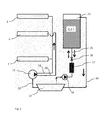
- Fig. 2 lets this be seen by means of a functional representation.
- the sterilization device has a UV lamp 22 carried by a lamp holder 39.
- Fig. 2 are schematically illustrated the upper spray arm 5, the middle spray arm 6 and the lower spray arm 7. Via a line 14, the upper spray arm 5 and the lower spray arm 7 are connected to a circulation pump 11. The middle spray arm 6 is connected via a separate line 20 to the circulation pump 11.
- the circulating pump 11 is in turn connected via a line 13 with the collection pot 12 provided by the washing container 3 in fluid communication.
- circulating through the circulation pump 11 rinse liquor and fed either via the line 14 to the upper spray arm 5 and the lower spray arm 7 or via the line 20 to the middle spray arm 6.
- the items to be cleaned is treated with wash liquor, from where it enters the collection pot 12.
- the reservoir 10 is also fluidly connected via a line 15. Rinse liquor can be removed from the collecting pot 12 via an additional pump 16 and transferred to the storage reservoir 10.
- the line 15 in addition to the auxiliary pump 16 nor the sterilizing filter 17 and a valve 18 are turned on. In this case, the line 15 can be closed or opened by means of the valve 18.
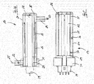
- the sterilization device 17 has a cylindrically shaped housing 21. This is equipped with a connecting piece 23. Within the housing 21, a hollow cylinder 35 is arranged. In this case, the hollow cylinder 35 to form an annular Gap space, that is an annular space 28 received by the housing 21. The annular space 28 is in turn connected to a connecting piece 24.
- the UVC lamps emit radiation having a wavelength in the range of 280nm to 200nm, preferably 254nm.
- the hollow cylinder 35 is formed of a material which transmits the radiation emitted by the UVC lamp, for example ETFE or quartz glass.
- FIGS. 3a and 3b The mode of operation of the degerming device 17 results from the illustrations according to FIGS. 3a and 3b , in which Fig. 3a the so-called degerming function and Fig. 3b represent the so-called cleaning function.
- Fig. 3a polluted rinsing flows in accordance with the arrow 25 via the connecting piece 23 in the housing 21 a. This is guided in accordance with the arrows 26 through the annular space 28 to the connecting piece 24, via which it exits the sterilization application 17 in accordance with the arrow 27 again.
- the UVC lamps 22 are turned on for the purpose of sterilizing the rinsing liquor and emit their radiation in correspondence of the arrows 38 in the direction of the annular space 28 through which the rinsing liquor flows.
- the bacteria, germs and / or the like possibly contained in the rinsing liquor are inactivated, that is to say killed. Consequently, sterilized rinsing fluid flows out of the degerminating device 17 via the connection 24, from where it then reaches the reservoir 10 in the manner already described above.
- the cleaning function is in Fig. 3b shown.
- deposits can accumulate inside the housing 21 and the outside of the UV lamps 22 receiving hollow cylinder. These are removed by means of a scraper 29 described in more detail below from the inner wall 36 of the housing 21 and the outer wall 37 of the hollow cylinder 35. It can then be carried out a flushing out of the dissolved deposits, for which purpose rinsing liquor is introduced via the connecting piece 23 into the sterilizing device 17.
- the rinsing liquor passes via the connecting piece 23 into the annular space 28, takes there the previously detached by means of the scraper 29 deposits and leaves the degerming device 17 via the connecting piece 24 in accordance with the arrow 27th According to this procedure, a rinsing of the degerming device 17 is carried out with not previously sterilized rinsing liquor.
- a flushing of the sterilizing device 17 can also be carried out with previously sterilized rinsing liquor.
- a backwash takes place in a for presentation Fig. 3b reverse direction.
- Previously sterilized and cached in reservoir 10 rinse liquor passes through the connecting piece 24 in the space provided by the sterilization device 17 annulus.
- There existing particles, impurities, contaminants and / or the like are then entrained and flushed out through the pipe 23, whereby via the connecting piece 23, a return to the collecting pot 12 of the washing compartment 3 takes place.
- a ring-shaped scraper 29 is arranged in the annular space 28 of the degerminator 17. This scraper 29 is slidably guided in the housing 21 and can with respect to the drawing plane to Fig. 5 be moved from top to bottom or in the opposite direction.
- the scraper 29 is on the one hand with the inner side 36 of the housing 21 and on the other hand with the outer side 37 of the hollow cylinder 35 in contact. As a result of a movement of the scraper 29 any deposits on the inside 36 of the housing 21 and / or on the outside 37 of the hollow cylinder 35 entrained, so that it comes to a cleaning of the housing 21 and / or the hollow cylinder 35.
- a part-circular trained driver 31 which is formed on the outside of the housing 21.
- the Driver 31 has a in the Fign. not shown in detail franking for the connecting piece 23rd
- the driver 31 and the wiper 29 act magnetically together, for which purpose the wiper 29 has corresponding magnets 30. During a movement of the driver 31, the scraper 29 follows due to the magnetic effect.
- the driver 31 is mechanically coupled to the Spülraumt 9 of the dishwasher 1, for which purpose a guided over pulleys 33 Bowden cable 32 is provided. If there is a pivoting movement of the Spül mattersert 9, then via the Bowden cable 32 a movement of the driver 31 depending on the door movement with respect to the drawing plane after Fig. 5 either brought up or down. As a result of this movement also moves the cooperating with the driver 31 scraper 29 so that it comes as a result of pivoting the Spülraume 9 to a cleaning of the filter fabric 2.
- Fig. 6 can be seen in a schematic representation of an example installation situation.
- This illustration shows the flushing chamber door 9, which is coupled to the Bowden cable 32 via a movement device 34.
- the Bowden cable 32 is in turn coupled in the manner already described to the driver 31 of the degerminator 17.
- the driver 31 is in closed Spülraumt 9 in its lower position. If the Spülraumt 9 is opened, that is with respect to the drawing level after Fig. 6 pivoted to the left, moves the driver 31 with respect to the plane of the drawing Fig. 6 up. If the Spülraumt 9 is closed, the driver 31 moves in the opposite direction, that is, with respect to the plane of the drawing Fig. 6 downward.
- a in the Fign. not shown filter device be part of the degerminator 17. It is preferred that the filter device has a filter fabric arranged in the housing 21, which is preferably cylindrical. The filter fabric can be arranged inside the annular space 28 and serve for pre-filtering and / or subsequent filtering of the rinsing liquor. It is preferred to form the scraper in two parts, so that not only a cleaning of the housing 21 and the hollow cylinder 35 but also a cleaning of the filter fabric takes place in the case of the movement.
Landscapes
- Physical Water Treatments (AREA)
- Apparatus For Disinfection Or Sterilisation (AREA)
- Washing And Drying Of Tableware (AREA)
Abstract
Description
- Die Erfindung betrifft einen Geschirrspülautomaten, insbesondere einen Geschirrspülautomaten zur Verwendung im Haushalt, mit einem einen Spülraum bereitstellenden Spülbehälter, der eine mittels einer verschwenkbar gelagerten Spülraumtür verschließbare Beschickungsöffnung aufweist, und mit einem Vorratsbehälter für die Zwischenspeicherung von Spülflotte.
- Geschirrspülautomaten der eingangs genannten Art sind aus dem Stand der Technik gut bekannt. Sie verfügen über einen einen Spülraum bereitstellenden Spülbehälter, der im bestimmungsgemäßen Verwendungsfall der Aufnahme von zu reinigendem Spülgut dient. Zur Beschickung des Spülbehälters dient eine Beschickungsöffnung, die mittels einer verschwenkbar gelagerten Spülraumtür fluiddicht verschließbar ist.
- Für eine Beaufschlagung von zu reinigendem Spülgut mit Spülflotte dienen innerhalb des Spülbehälters verdrehbar angeordnete Sprüharme. Diese werden über eine Umwälzpumpe mit Spülflotte versorgt. Je nach Ausgestaltung des Geschirrspülautomaten sind bevorzugterweise zwei oder drei Sprüharme vorgesehen.
- Aus dem Stand der Technik ist es ferner bekannt, Geschirrspülautomaten der eingangs genannten Art zum Zwecke der Wassereinsparung mit einem Vorratsbehälter zur Zwischenspeicherung von Spülflotte auszurüsten. Dieser Vorratsbehälter dient dazu, am Ende eines bestimmungsgemäßen Programmablaufes im Spülbehälter noch befindliche Restspülflotte aufzunehmen und bis zum Beginn eines nächsten Spülprogramms zu bevorraten. Typischerweise wird die zum Ende eines Spülprogramms verhältnismäßig saubere Klarspülflotte zur Zwischenspeicherung genutzt. Mit Beginn eines neuen Spülprogramms wird die zwischengespeicherte Spülflotte in den Spülbehälter abgelassen, so dass eine um die Menge an zurückgeführter Spülflotte reduzierte Menge an Frischwasser für den Beginn des neuen Spülprogramms erforderlich ist.
- Die innerhalb des Vorratsbehälters zwischengespeicherte Spülflotte unterliegt der Verkeimung. Diese ergibt sich häufig einhergehend mit einer Geruchsbelästigung. Um dem entgegenzuwirken, sind aus dem Stand der Technik zahlreiche unterschiedliche Maßnahmen bekannt geworden. So ist zum Beispiel vorgeschlagen worden, in die strömungstechnische Verbindung zwischen Spülbehälter und Vorratsbehälter einen Filter einzusetzen. Dabei ist es Sinn und Zweck eines solchen Filters, in der Spülflotte befindliche Partikel, Verunreinigungen, Verschmutzungen und/oder dergleichen herauszufiltern, bevor die Spülflotte zwecks Zwischenspeicherung in den Vorratsbehälter überführt wird.
- Obgleich sich der Einsatz eines Filters zur Reinigung der Spülflotte dem Grunde nach bewährt hat, bestehen gewisse Nachteile, insbesondere in der Handhabung. So setzt sich das Filtergewebe mit fortgesetzter Anwendungsdauer nach und nach zu. Um weiterhin eine bestimmungsgemäße Funktionstüchtigkeit gewährleisten zu können, ist eine Reinigung des Filters erforderlich. Dies wird verwenderseitig als lästig empfunden, weshalb es regelmäßig mit der Folge unterbleibt, dass der Vorratsbehälter wegen Verstopfens des Filters nicht in dem möglichen Maße mit Spülflotte zum Zwecke der Zwischenspeicherung aufgefüllt wird.
- Ausgehend vom Vorbeschriebenen ist es die Aufgabe der Erfindung, einen Geschirrspülautomaten der eingangs genannten Art vorzuschlagen, der eine insgesamt vereinfachte Handhabung ermöglicht.
- Zur Lösung dieser Aufgabe wird mit der Erfindung ein Geschirrspülautomat der eingangs genannten Art vorgeschlagen, der sich auszeichnet durch eine in die strömungstechnische Verbindung zwischen Spülbehälter und Vorratsbehälter eingesetzten Keimungseinrichtung, wobei die Entkeimungseinrichtung ein Gehäuse, eine darin angeordnete UV-Lampe sowie einen mit der UV-Lampe und dem Gehäuse zusammenwirkenden Abstreifer aufweist, wobei der Abstreifer im Gehäuse verschieblich gelagert ist.
- Der mit der Erfindung vorgeschlagene Geschirrspülautomat verfügt über eine Entkeimungseinrichtung. Diese Entkeimungseinrichtung wird von der Spülflotte vor einem Einströmen in den Vorratsbehälter passiert, wodurch es zu einer Entkeimung derselben kommt. Zur Zwischenspeicherung in den Vorratsbehälter gelangt mithin entkeimte Spülflotte.
- Die Entkeimungseinrichtung verfügt über ein Gehäuse. Innerhalb des Gehäuses ist eine UV-Lampe angeordnet bei der UV-Lampe handelt es sich bevorzugterweise um eine UVC-Lampe, das heißt um eine Lampe, die Licht im ultravioletten Spektrum im Wellenlängenbereich zwischen 280 nm und 200 nm abgibt.
- Die UV-Lampe stellt das Herzstück der Entkeimungseinrichtung dar. Sie wird im Falle der bestimmungsgemäßen Beaufschlagung mit Spülflotte, das heißt im Falle der Überführung von Spülflotte aus dem Spülbehälter in den Vorratsbehälter eingeschaltet. Die von ihr abgegebene Strahlung wirkt auf die in die Entkeimungseinrichtung eingeführte Spülflotte ein, infolge dessen es zu einer Inaktivierung, das heißt Abtötung von Bakterien, Keimen und/oder dergleichen biologischen Substanzen kommt. Im Ergebnis der Vorbeiführung der Spülflotte an der UV-Lampe der Entkeimungseinrichtung ist die Spülflotte entkeimt, so dass es zur Zwischenspeicherung von entkeimter Spülflotte im Vorratsbehälter kommt.
- Infolge des Hindurchführens von zu entkeimender Spülflotte durch die Entkeimungseinrichtung kann es am Gehäuse der Entkeimungseinrichtung und/oder an der UV-Lampe zu Ablagerungen von aus der Spülflotte stammenden Partikeln, Verunreinigungen, Verschmutzungen und/oder dergleichen kommen. Insbesondere etwaige Ablagerungen an der UV-Lampe können die bestimmungsgemäße Funktionsweise der Entkeimungseinrichtung stören, da im bestimmungsgemäßen Verwendungsfall von der UV-Lampe abgegebene Strahlung nicht mehr in vollem Umfang die zu entkeimende Spülflotte erreichen kann.
- Um einer Verunreinigung der Entkeimungseinrichtung vorzubeugen, ist diese mit einem Abstreifer ausgerüstet, der mit der UV-Lampe einerseits und dem Gehäuse andererseits zusammenwirkt. Der Abstreifer ist im Gehäuse verschieblich geführt, so dass er im Falle einer bestimmungsgemäßen Verschiebebewegung insbesondere an der UV-Lampe entlangfährt und dabei etwaige Ablagerungen von Partikeln, Verunreinigungen, Verschmutzungen und/oder dergleichen abstreift. In einer Rückspülung können diese durch den Abstreifer entfernten Ablagerungen zurück in den Spülraum befördert werden, von wo aus sie durch Abpumpen entsorgt werden können. Dabei erfolgt ein solches Abpumpen bevorzugterweise während einer nachfolgenden bestimmungsgemäßen Programmdurchführung.
- Die nach der Erfindung vorgesehene Entkeimungseinrichtung ist selbstreinigend. Der im Gehäuse der Entkeimungseinrichtung geführte Abstreifer sorgt dafür, dass sich in der Entkeimungseinrichtung insbesondere an der UV-Lampe ausbildende Ablagerungen entfernt werden, so dass eine Rückführung derselben in den Spülbehälter gestattet ist. Ein Zusetzen der Entkeimungseinrichtung ist damit unterbunden. Eine vom Verwender durchzuführende manuelle Reinigung ist in vorteilhafter Weise nicht erforderlich.
- Im bestimmungsgemäßen Verwendungsfall erfolgt über die erfindungsgemäß vorgesehene Entkeimungseinrichtung eine Entkeimung der dem Vorratsbehälter zuzuführende Spülflotte. Zur Zwischenspeicherung im Vorratsbehälter gelangt mithin entkeimte Spülflotte, so dass die Gefahr von Verkeimungen im Vorratsbehälter und die damit einhergehende Gefahr von Geruchsbelästigungen minimiert ist. Bei einer Rückführung der Spülflotte in den Spülbehälter erfolgt eine Rückspülung der Entkeimungseinrichtung, so dass sich unter Umständen zuvor in der Entkeimungseinrichtung ausgebildete Ablagerungen in den Spülbehälter strömen, wo es dann im Zuge einer bestimmungsgemäßen Programmdurchführung zu einer Entsorgung derselben kommt. Dabei sorgt der erfindungsgemäß vorgesehene Abstreifer dafür, dass eine Reinigung der Entkeimungseinrichtung durchgeführt wird, so dass eine verwenderseitige manuelle Reinigung nicht von Nöten ist.
- Gemäß einem besonderen Vorschlag der Erfindung ist vorgesehen, dass die Entkeimungseinrichtung einen mit dem Abstreifer zusammenwirkenden Mitnehmer aufweist, der außenseitig des Gehäuses an diesem verschieblich angeordnet ist. Dabei weist der Abstreifer und/oder der Mitnehmer einen Magneten auf und/oder der Abstreifer beziehungsweise der Mitnehmer sind zumindest teilweise als Magnet ausgebildet. Bei einer Verfahrbewegung des Mitnehmers kommt es aufgrund der zwischen dem Mitnehmer und dem Abstreifer wirkenden magnetischen Kraft zu einer Verfahrbewegung auch des Abstreifers. Der Abstreifer folgt in seiner Bewegung mithin der durch den Mitnehmer vorgegebenen Bewegung.
- Der Mitnehmer ist mechanisch mit der Spülraumtür gekoppelt, zu welchem Zweck bevorzugterweise ein Bowdenzug vorgesehen ist. Bei einer Verschwenkbewegung der Spülraumtür kommt es so zu einer Verfahrbewegung des über den Bowdenzug mit der Spülraumtür gekoppelten Mitnehmers. Dieser wirkt wiederum magnetische mit dem Abstreifer zusammen, so dass es infolge einer Bewegung der Spülraumtür im Ergebnis zu einer Verfahrbewegung des mit insbesondere der UV-Lampe zusammenwirkenden Abstreifers kommt. Bei jeder verwenderseitigen Betätigung der Spülraumtür kommt es damit zu einer Verfahrbewegung des Abstreifers und damit zu einer Entfernung von etwaigen Ablagerungen am Gehäuse und/oder der UV-Lampe der Entkeimungseinrichtung.
- Die UV-Lampe ist gemäß einem besonderen Merkmal der Erfindung innerhalb eines Hohlzylinders angeordnet. Dieser Hohlzylinder ist unter Belassung eines ringförmigen Spaltraums in das Gehäuse der Entkeimungseinrichtung eingesetzt. Dieser Hohlzylinder dient zum Schutz der UV-Lampe und ist aus einem für die von der UV-Lampe abgegebene Strahlung durchlässigen Material gebildet. Ein direkter Kontakt der Spülflotte mit der UV-Lampe findet gemäß dieser Ausgestaltungsform nicht statt. Die Spülflotte strömt vielmehr außenseitig des die UV-Lampe aufnehmenden Hohlzylinders entlang.
- Der Abstreifer ist gemäß einem weiteren Merkmal der Erfindung ringförmig ausgebildet und innerhalb des ringförmigen Spaltraums zwischen Gehäuse einerseits und Hohlzylinder andererseits angeordnet. Innerhalb dieses Ringspalts kann der Abstreifer in Höhenrichtung des Gehäuses verfahren werden. Dabei steht der Abstreifer bevorzugterweise sowohl mit der Innenseite des Gehäuses als auch mit der Außenseite des Hohlzylinders in Kontakt. Infolge dessen kommt es bei einer Verfahrbewegung des Abstreifers zur Entfernung von etwaigen Ablagerungen, die sich auf der Innenseite des Gehäuses und/oder auf der Außenseite des Hohlzylinders ausbilden können. Bei einer Verfahrbewegung des Abstreifers fährt dieser sowohl an der Innenseite des Gehäuses als auch an der Außenseite des Holzylinders entlang, infolge dessen es zu einem Mitbeziehungsweise Abreißen etwaiger hier befindlicher Ablagerungen kommt.
- Innerhalb des Hohlzylinders können eine Mehrzahl von UV-Lampen angeordnet sein. Die Strahlungsintensität kann so erhöht werden. Dabei sind die UV-Lampen bevorzugterweise stabförmig ausgebildet und nebeneinander innerhalb des Hohlzylinders platziert.
- Die vorbeschriebene Konstruktion erweist sich als besondere anwendungsfreundlich. Eine Wartung der einzelnen Baukomponenten ist nicht erforderlich. Insgesamt ergibt sich damit eine vereinfachte Handhabung des Geschirrspülautomatens, wobei eine Entkeimung der im Vorratsbehälter zwischen zu speichernden Spülflotte sichergestellt ist.
- Weitere Vorteile und Merkmale der Erfindung ergeben sich aus der nachfolgenden Beschreibung anhand der Figuren. Dabei zeigen
- Fig. 1
- in schematischer Darstellung einen Geschirrspülautomaten nach der Erfindung,
- Fig. 2
- in einer schematischen Funktionsdarstellung den erfindungsgemäßen Geschirrspülautomaten;
- Fig. 3a
- in einer schematischen Darstellung die Entkeimungseinrichtung nach der Erfindung gemäß einer ersten Funktionsweise;
- Fig. 3b
- in einer schematischen Darstellung die Entkeimungseinrichtung nach der Erfindung gemäß einer zweiten Funktionsweise;
- Fig. 4
- in schematisch perspektivischer Darstellung die Entkeimungseinrichtung nach der Erfindung;
- Fig. 5
- in schematischer Seitenansicht die Entkeimungseinrichtung nach
Fig. 4 und - Fig. 6
- in einer schematischen Darstellung die erfindungsgemäße Entkeimungseinrichtung in Einbausituation.
-
Fig. 1 lässt in schematischer Darstellung einen Geschirrspülautomaten 1 erkennen. Dieser verfügt über ein Gehäuse 2, das einen einen Spülraum 4 bereitstellenden Spülbehälter 3 aufnimmt. Der Spülbehälter 3 dient im bestimmungsgemäßen Verwendungsfall der Aufnahme von zu reinigendem Spülgut. - Der vom Spülbehälter 3 bereitgestellte Spülraum 4 ist über eine Beschickungsöffnung 8 zugänglich. Diese ist mittels einer verschwenkbar am Gehäuse 2 angeordneten Spülraumtür 9 fluiddicht verschließbar.
- Zur Beschickung von zu reinigendem Spülgut mit Spülflotte sind innerhalb des Spülbehälters 3 Sprüharme angeordnet, wobei im gezeigten Ausführungsbeispiel insgesamt drei Sprüharme vorgesehen sind, und zwar ein oberer Sprüharm 5, ein mittlerer Sprüharm 6 sowie ein unterer Sprüharm 7.
- Der Geschirrspülautomat 1 verfügt desweiteren über einen Vorratsbehälter 10 für die Zwischenspeicherung von Spülflotte. Dieser Vorratsbehälter 10 kann innerhalb des Gehäuses 2 oder auch außerhalb desselben ausgebildet sein. Im gezeigten Ausführungsbeispiel ist der Vorratsbehälter 10 im nicht näher dargestellten Spaltraum zwischen Spülbehälter 3 einerseits und Gehäuse 2 andererseits untergebracht.
- Der Vorratsbehälter 10 ist strömungstechnisch mit dem Spülbehälter 3 gekoppelt. Über diese strömungstechnische Verbindung kann dem Spülbehälter 3 Spülflotte entnommen und dem Vorratsbehälter 10 zugeführt beziehungsweise in umgekehrter Richtung aus dem Vorratsbehälter 10 in den Spülbehälter 3 überführt werden.
- Der Vorratsbehälter 10 dient der Zwischenspeicherung von Spülflotte. Typischerweise wird dem Spülbehälter 3 zum Ende eines bestimmungsgemäß durchlaufenen Spülprogramms Spülflotte entnommen und im Vorratsbehälter 10 bis zum Beginn eines nächsten Spülprogramms zwischengespeichert. Damit erlaubt der Vorratsbehälter 10 die Zwischenspeicherung von Spülflotte, womit die insgesamt für einen bestimmungsgemäßen Programmablauf benötigte Menge an Frischwasser reduziert werden kann, da mit Beginn eines neuen Spülprogramms aus einem vorangegangenen Spülprogramm stammende Spülflotte genutzt werden kann. Es findet insofern eine Wiederverwendung von Spülflotte statt.
- Typische Vorratsbehälter 10 haben ein Speichervolumen von zwei Liter, drei Liter oder vier Liter.
- Die im Vorratsbehälter 10 zwischengespeicherte Spülflotte verkeimt im Laufe der Zeit und es können sich Ablagerungen, Bio-Filme und dergleichen im Inneren des Vorratsbehälters 10 ausbilden. Hierdurch können unangenehme Gerüche entstehen. Es besteht zudem die Gefahr, dass sich etwaige Ablagerungen, Bio-Filme und/oder dergleichen ablösen, was dann zu einer Funktionsbeeinträchtigung oder sogar zu einem Komplettausfall des Vorratsbehälters 10 oder sogar des gesamten Geschirrspülautomaten 1 führen kann.
- Um dieser Problematik vorzubeugen, ist erfindungsgemäß eine Entkeimungseinrichtung 17 vorgesehen, die in die strömungstechnische Verbindung zwischen Spülbehälter 3 und Vorratsbehälter 10 eingesetzt ist.
Fig. 2 lässt dies anhand einer Funktionsdarstellung erkennen. Die Entkeimungseinrichtung verfügt über eine von einer Lampenfassung 39 getragene UV-Lampe 22. - In
Fig. 2 sind schematisch dargestellt der obere Sprüharm 5, der mittlere Sprüharm 6 sowie der untere Sprüharm 7. Über eine Leitung 14 sind der obere Sprüharm 5 und der untere Sprüharm 7 an eine Umwälzpumpe 11 angeschlossen. Der mittlere Sprüharm 6 ist über eine separate Leitung 20 an die Umwälzpumpe 11 angeschlossen. - Die Umwälzpumpe 11 steht ihrerseits über eine Leitung 13 mit dem vom Spülbehälter 3 bereitgestellten Sammeltopf 12 in strömungstechnischer Verbindung. Im bestimmungsgemäßen Verwendungsfall wird über die Umwälzpumpe 11 Spülflotte umgewälzt und entweder über die Leitung 14 dem oberen Sprüharm 5 und dem unteren Sprüharm 7 oder über die Leitung 20 dem mittleren Sprüharm 6 zugeführt. Über die Sprüharme 5, 6 und 7 wird das zu reinigende Spülgut mit Spülflotte beaufschlagt, von wo aus sie in den Sammeltopf 12 gelangt.
- An den Sammeltopf 12 ist ferner der Vorratsbehälter 10 strömungstechnisch über eine Leitung 15 angeschlossen. Über eine Zusatzpumpe 16 kann Spülflotte dem Sammeltopf 12 entnommen und in den Vorratsspeicher 10 überführt werden. In die Leitung 15 sind neben der Zusatzpumpe 16 noch die Entkeimungseinrichtung Filter 17 sowie ein Ventil 18 eingeschaltet. Dabei kann mittels des Ventils 18 die Leitung 15 geschlossen oder geöffnet werden.
- Über eine Leitung 19 erfolgt eine Rückführung der zwischengespeicherten Spülflotte aus dem Vorratsbehälter 10 zurück in den Sammeltopf 12.
- Die in die Leitung 15 eingesetzte Entkeimungseinrichtung 17 ist in den
Fig. 4 und5 dargestellt. Wie diesen Fign. zu entnehmen ist, verfügt die Entkeimungseinrichtung 17 über ein zylinderförmig ausgebildetes Gehäuses 21. Dieses ist mit einem Anschlussstutzen 23 ausgerüstet. Innerhalb des Gehäuses 21 ist ein Hohlzylinder 35 angeordnet. Dabei ist der Hohlzylinder 35 unter Ausbildung eines ringförmigen Spaltraums, das heißt eines Ringraums 28 vom Gehäuse 21 aufgenommen. Der Ringraum 28 ist seinerseits an einen Anschlussstutzen 24 angeschlossen. - Innerhalb des Hohlzylinders 35 sind im gezeigten Ausführungsbeispiel zwei stabförmig ausgebildete UVC-Lampen angeordnet. Die UVC-Lampen geben eine Strahlung mit einer Wellenlänge im Bereich von 280nm bis 200nm, vorzugsweise von 254nm ab. Der Hohlzylinder 35 ist aus einem Material gebildet, der die von der UVC-Lampe abgegebene Strahlung durchlässt, beispielsweise ETFE oder Quarzglas.
- Die Funktionsweise der Entkeimungseinrichtung 17 ergibt sich aus den Darstellungen nach den
Fign. 3a und3b , wobeiFig. 3a die sogenannte Entkeimungsfunktion undFig. 3b die sogenannte Reinigungsfunktion darstellen. - Gemäß der Darstellung nach
Fig. 3a strömt verschmutzte Spülflotte in Entsprechung des Pfeils 25 über den Anschlussstutzen 23 in das Gehäuse 21 ein. Diese wird in Entsprechung der Pfeile 26 durch den Ringraum 28 bis zum Anschlussstutzen 24 geführt, über den sie die Entkeimungseinreichung 17 in Entsprechung des Pfeils 27 wieder verlässt. Im bestimmungsgemäßen Verwendungsfall sind die UVC-Lampen 22 zum Zwecke der Entkeimung der Spülflotte eingeschaltet und geben ihre Strahlung in Entsprechung der Pfeile 38 in Richtung auf den von der Spülflotte durchströmten Ringraum 28 ab. Infolge der Bestrahlung werden die in der Spülflotte unter Umständen enthaltenen Bakterien, Keime und/oder dergleichen inaktiviert, das heißt abgetötet. Über den Stutzen 24 strömt mithin entkeimte Spülflotte aus der Entkeimungseinrichtung 17, von wo aus sie dann in der schon vorbeschriebenen Weise zum Vorratsbehälter 10 gelangt. - Die Reinigungsfunktion ist in
Fig. 3b dargestellt. Im Zuge einer bestimmungsgemäßen Verwendung können sich innenseitig des Gehäuses 21 und außenseitig des die UV-Lampen 22 aufnehmenden Hohlzylinders 35 Ablagerungen ansammeln. Diese werden mittels eines im Weiteren noch näher beschriebenen Abstreifers 29 von der Innenwand 36 des Gehäuses 21 beziehungsweise der Außenwand 37 des Hohlzylinders 35 entfernt. Es kann sodann ein Herausspülen der gelösten Ablagerungen erfolgen, zu welchem Zweck Spülflotte über den Anschlussstutzen 23 in die Entkeimungseinrichtung 17 eingeführt wird. Die Spülflotte gelangt über den Anschlussstutzen 23 in den Ringraum 28, nimmt dort die zuvor mittels des Abstreifers 29 abgelösten Ablagerungen mit und verlässt die Entkeimungseinrichtung 17 über den Anschlussstutzen 24 in Entsprechung des Pfeils 27. Gemäß dieser Verfahrensdurchführung erfolgt eine Spülung der Entkeimungseinrichtung 17 mit nicht zuvor entkeimter Spülflotte. - Gemäß einer alternativen Verfahrensdurchführung kann eine Durchspülung der Entkeimungseinrichtung 17 auch mit zuvor entkeimter Spülflotte durchgeführt werden. In diesem Fall erfolgt eine Rückspülung in einer zur Darstellung nach
Fig. 3b umgekehrten Richtung. Zuvor entkeimte und in Vorratsbehälter 10 zwischengespeicherte Spülflotte gelangt über den Anschlussstutzen 24 in den von der Entkeimungseinrichtung 17 bereitgestellten Ringraum. Dort vorhandene Partikel, Verunreinigungen, Verschmutzungen und/oder dergleichen werden sodann mitgerissen und über den Stutzen 23 ausgespült, wobei über den Anschlussstutzen 23 eine Rückführung in den Sammeltopf 12 des Spülbehälters 3 erfolgt. - Wie die Darstellung nach
Fig. 2 erkennen lässt, erfolgt eine Rückführung der im Vorratsbehälter 10 gespeicherten Spülflotte zurück in den Spülbehälter 3 über die Leitung 19. Ein Teil der im Vorratsbehälter 10 gespeicherten Spülflotte wird bei geöffnetem Ventil 18 gemäß vorbeschriebener Verfahrensalternative für die vorbeschriebenen Rückspülung der Entkeimungseinrichtung 17 genutzt, und sie strömt über die Leitung 15 aus dem Vorratsbehälter 10 zurück in den Sammeltopf 12. - Wie insbesondere die Darstellungen nach den
Fign. 4 und5 erkennen lassen, ist im Ringraum 28 der Entkeimungseinrichtung 17 ein ringförmig ausgebildeter Abstreifer 29 angeordnet. Dieser Abstreifer 29 ist im Gehäuse 21 verschieblich geführt und kann mit Bezug auf die Zeichnungsebene nachFig. 5 von oben nach unten beziehungsweise in umgekehrter Richtung verfahren werden. - Der Abstreifer 29 steht einerseits mit der Innenseite 36 des Gehäuses 21 und andererseits mit der Außenseite 37 des Hohlzylinders 35 in Kontakt. Infolge einer Verfahrbewegung des Abstreifers 29 werden etwaige Ablagerungen an der Innenseite 36 des Gehäuses 21 und/oder an der Außenseite 37 des Hohlzylinders 35 mitgerissen, so dass es zu einer Reinigung des Gehäuses 21 und/oder des Hohlzylinders 35 kommt.
- Zur Einleitung einer Verfahrbewegung des Abstreifers 29 dient ein teilkreisförmig ausgebildeter Mitnehmer 31, der außenseitig des Gehäuses 21 ausgebildet ist. Der Mitnehmer 31 verfügt über eine in den Fign. nicht näher dargestellte Freimachung für den Anschlussstutzen 23.
- Der Mitnehmer 31 und der Abstreifer 29 wirken magnetisch zusammen, zu welchem Zweck der Abstreifer 29 über entsprechende Magnete 30 verfügt. Bei einer Verfahrbewegung des Mitnehmers 31 folgt der Abstreifer 29 aufgrund der Magnetwirkung nach.
- Der Mitnehmer 31 ist mechanisch mit der Spülraumtür 9 des Geschirrspülautomatens 1 gekoppelt, zu welchem Zweck ein über Umlenkrollen 33 geführter Bowdenzug 32 vorgesehen ist. Kommt es zu einer Verschwenkbewegung der Spülbehältertür 9, so wird über den Bowdenzug 32 eine Verfahrbewegung des Mitnehmers 31 je nach Türbewegung mit Bezug auf die Zeichnungsebene nach
Fig. 5 entweder nach oben oder nach unten herbeigeführt. Infolge dieser Verfahrbewegung verfährt auch der mit dem Mitnehmer 31 zusammenwirkende Abstreifer 29, so dass es infolge einer Verschwenkung der Spülraumtür 9 zu einer Reinigung des Filtergewebes 2 kommt. -
Fig. 6 lässt in schematischer Darstellung beispielhaft eine Einbausituation erkennen. Zu entnehmen ist dieser Darstellung die Spülraumtür 9, die über eine Bewegungseinrichtung 34 mit dem Bowdenzug 32 gekoppelt ist. Der Bowdenzug 32 ist wiederum in der schon vorbeschriebenen Weise an den Mitnehmer 31 der Entkeimungseinrichtung 17 angekoppelt. Wie sich aus dieser Darstellung ergibt, befindet sich der Mitnehmer 31 bei verschlossener Spülraumtür 9 in seiner unteren Stellung. Wird die Spülraumtür 9 geöffnet, das heißt mit Bezug auf die Zeichnungsebene nachFig. 6 nach links verschwenkt, verfährt der Mitnehmer 31 mit Bezug auf die Zeichnungsebene nachFig. 6 nach oben. Wird die Spülraumtür 9 geschlossen, so verfährt der Mitnehmer 31 in entgegengesetzter Richtung, das heißt mit Bezug auf die Zeichnungsebene nachFig. 6 nach unten. - Gemäß einem weiteren Merkmal der Erfindung kann eine in den Fign. nicht näher dargestellte Filtereinrichtung Bestandteil der Entkeimungseinrichtung 17 sein. Dabei ist bevorzugt, dass die Filtereinrichtung ein im Gehäuse 21 angeordnetes Filtergewebe aufweist, das bevorzugterweise zylindrisch ausgebildet ist. Das Filtergewebe kann innerhalb des Ringraums 28 angeordnet sein und einer Vor- und/oder Nachfilterung der Spülflotte dienen. Dabei ist es bevorzugt, den Abstreifer zweiteilig auszubilden, so dass durch diesen im Falle der Verfahrbewegung nicht nur eine Reinigung des Gehäuses 21 und des Hohlzylinders 35 sondern auch eine Reinigung des Filtergewebes stattfindet.
Bezugszeichenliste 1 Geschirrspülautomat 21 Gehäuse 2 Gehäuse 22 UV-Lampe 3 Spülbehälter 23 Anschlussstutzen 4 Spülraum 24 Anschlussstutzen 5 oberer Sprüharm 25 Pfeil 6 mittlerer Sprüharm 26 Pfeil 7 unterer Sprüharm 27 Pfeil 8 Beschickungsöffnung 28 Ringraum 9 Spülraumtür 29 Abstreifer 10 Vorratsbehälter 30 Magnet 11 Umwälzpumpe 31 Mitnehmer 12 Sammeltopf 32 Bowdenzug 13 Leitung 33 Umlenkrolle 14 Leitung 34 Bewegungseinrichtung 15 Leitung 35 Hohlzylinder 16 Zusatzpumpe 36 Innenseite 17 Entkeimungseinrichtung 37 Außenseite 18 Ventil 38 Pfeil 19 Leitung 39 Lampenfassung 20 Leitung
Claims (12)
- Geschirrspülautomat mit einem einen Spülraum (4) bereitstellenden Spülbehälter (3), der eine mittels einer verschwenkbar gelagerten Spülraumtür (9) verschließbare Beschickungsöffnung (8) aufweist, und mit einem Vorratsbehälter (10) für die Zwischenspeicherung von Spülflotte, der strömungstechnisch an den Spülbehälter (3) angeschlossen ist,
gekennzeichnet durch
eine in die strömungstechnische Verbindung zwischen Spülbehälter (3) und Vorratsbehälter (10) eingesetzte Entkeimungseinrichtung (17), wobei die Entkeimungseinrichtung (17) ein Gehäuse (21), eine darin angeordnete UV-Lampe (22) sowie einen mit der UV-Lampe (22) und dem Gehäuse (21) zusammenwirkenden Abstreifer (29) aufweist, wobei der Abstreifer (29) in Gehäuse (21) verschieblich geführt ist. - Geschirrspülautomat nach Anspruch 1,
dadurch gekennzeichnet,
dass die Entkeimungseinrichtung (17) einen mit dem Abstreifer (29) zusammenwirkenden Mitnehmer (31) aufweist, der außenseitig des Gehäuses (21) an diesem verschieblich angeordnet ist. - Geschirrspülautomat nach Anspruch 2,
dadurch gekennzeichnet,
dass der Abstreifer (29) und/oder der Mitnehmer (31) einen Magneten aufweist/aufweisen und/oder zumindest teilweise als Magnet ausgebildet ist/sind. - Geschirrspülautomat nach einem der vorhergehenden Ansprüche,
dadurch gekennzeichnet,
dass der Mitnehmer (31) mit der Spülraumtür (9) mechanisch gekoppelt ist. - Geschirrspülautomat nach einem der vorhergehenden Ansprüche,
dadurch gekennzeichnet,
dass der Mitnehmer (31) unter Zwischenschaltung eines Bowdenzugs an die Spülraumtür (9) angeschlossen ist. - Geschirrspülautomat nach einem der vorhergehenden Ansprüche,
dadurch gekennzeichnet,
dass das Gehäuse (21) zylinderförmig ausgebildet ist. - Geschirrspülautomat nach einem der vorhergehenden Ansprüche,
dadurch gekennzeichnet,
dass der Mitnehmer (31) teilringförmig ausgebildet ist. - Geschirrspülautomat nach einem der vorhergehenden Ansprüche,
dadurch gekennzeichnet,
dass die UV-Lampe (22) von einem Hohlzylinder (35) aufgenommen ist, der unter Belassung eines ringförmigen Spaltraums (28) in das Gehäuse (21) eingesetzt ist. - Geschirrspülautomat nach Anspruch 8,
dadurch gekennzeichnet,
dass der Abstreifer (29) ringförmig ausgebildet und innerhalb des ringförmigen Spaltraums (28) geführt ist. - Geschirrspülautomat nach einem der vorhergehenden Ansprüche,
dadurch gekennzeichnet,
dass der Abstreifer (29) mit der Innenseite (36) des Gehäuses (21) und mit der Außenseite (37) des Hohlzylinders (35) in Kontakt steht. - Geschirrspülautomat nach einem der vorhergehenden Ansprüche,
dadurch gekennzeichnet,
dass innerhalb des Hohlzylinders (35) eine Mehrzahl von UV-Lampen (22) angeordnet sind. - Geschirrspülautomat nach einem der vorhergehenden Ansprüche,
dadurch gekennzeichnet,
dass die UV-Lampe (22) eine UVC-Lampe ist.
Priority Applications (1)
| Application Number | Priority Date | Filing Date | Title |
|---|---|---|---|
| PL13401038T PL2653087T3 (pl) | 2012-04-20 | 2013-04-15 | Zmywarka do naczyń |
Applications Claiming Priority (1)
| Application Number | Priority Date | Filing Date | Title |
|---|---|---|---|
| DE102012103497A DE102012103497A1 (de) | 2012-04-20 | 2012-04-20 | Geschirrspülautomat |
Publications (2)
| Publication Number | Publication Date |
|---|---|
| EP2653087A1 true EP2653087A1 (de) | 2013-10-23 |
| EP2653087B1 EP2653087B1 (de) | 2015-04-15 |
Family
ID=48446223
Family Applications (1)
| Application Number | Title | Priority Date | Filing Date |
|---|---|---|---|
| EP13401038.8A Active EP2653087B1 (de) | 2012-04-20 | 2013-04-15 | Geschirrspülautomat |
Country Status (3)
| Country | Link |
|---|---|
| EP (1) | EP2653087B1 (de) |
| DE (1) | DE102012103497A1 (de) |
| PL (1) | PL2653087T3 (de) |
Cited By (1)
| Publication number | Priority date | Publication date | Assignee | Title |
|---|---|---|---|---|
| CN104605802A (zh) * | 2015-02-27 | 2015-05-13 | 佛山市顺德区美的洗涤电器制造有限公司 | 洗碗机 |
Families Citing this family (1)
| Publication number | Priority date | Publication date | Assignee | Title |
|---|---|---|---|---|
| EP4456776A4 (de) * | 2021-12-30 | 2025-12-31 | Arcelik As | Geschirrspülmaschine mit uv-licht |
Citations (5)
| Publication number | Priority date | Publication date | Assignee | Title |
|---|---|---|---|---|
| DE3913355A1 (de) * | 1989-04-22 | 1990-10-25 | Licentia Gmbh | Programmgesteuerte wasch- oder geschirrspuelmaschine |
| DE4004057A1 (de) * | 1990-02-10 | 1991-08-14 | Miele & Cie | Programmgesteuertes haushaltgeraet, wie geschirrspuelmaschine oder waschmaschine, sowie verfahren zum betrieb des haushaltgeraetes |
| EP2397062A2 (de) * | 2011-07-12 | 2011-12-21 | V-Zug AG | Haushaltsgerät mit Tank zur Lagerung von Prozesswasser und mit Gassensor |
| DE102010038690A1 (de) * | 2010-07-30 | 2012-02-02 | BSH Bosch und Siemens Hausgeräte GmbH | Wasserführendes Haushaltsgerät, insbesondere Geschirrspülmaschine |
| WO2012084492A1 (en) * | 2010-12-24 | 2012-06-28 | Arcelik Anonim Sirketi | A dishwasher comprising a storage tank |
Family Cites Families (4)
| Publication number | Priority date | Publication date | Assignee | Title |
|---|---|---|---|---|
| DE1753071A1 (de) * | 1968-02-10 | 1971-07-01 | Rowenta Werke Gmbh | Lagerung der Tuer eines Haushaltsschrankes |
| DE19908583C2 (de) * | 1998-03-05 | 2002-10-24 | Wedeco Uv Verfahrenstechnik Gm | Vorrichtung zur kontinuierlichen Ermittlung der UV-Transmission fließender oder strömender Medien |
| EP0995483A1 (de) * | 1998-10-23 | 2000-04-26 | The Procter & Gamble Company | Querstromfiltrationsvorrichtung |
| CA2306546C (en) * | 2000-04-20 | 2006-06-27 | Photoscience Japan Corporation | Tube scraper |
-
2012
- 2012-04-20 DE DE102012103497A patent/DE102012103497A1/de not_active Ceased
-
2013
- 2013-04-15 EP EP13401038.8A patent/EP2653087B1/de active Active
- 2013-04-15 PL PL13401038T patent/PL2653087T3/pl unknown
Patent Citations (5)
| Publication number | Priority date | Publication date | Assignee | Title |
|---|---|---|---|---|
| DE3913355A1 (de) * | 1989-04-22 | 1990-10-25 | Licentia Gmbh | Programmgesteuerte wasch- oder geschirrspuelmaschine |
| DE4004057A1 (de) * | 1990-02-10 | 1991-08-14 | Miele & Cie | Programmgesteuertes haushaltgeraet, wie geschirrspuelmaschine oder waschmaschine, sowie verfahren zum betrieb des haushaltgeraetes |
| DE102010038690A1 (de) * | 2010-07-30 | 2012-02-02 | BSH Bosch und Siemens Hausgeräte GmbH | Wasserführendes Haushaltsgerät, insbesondere Geschirrspülmaschine |
| WO2012084492A1 (en) * | 2010-12-24 | 2012-06-28 | Arcelik Anonim Sirketi | A dishwasher comprising a storage tank |
| EP2397062A2 (de) * | 2011-07-12 | 2011-12-21 | V-Zug AG | Haushaltsgerät mit Tank zur Lagerung von Prozesswasser und mit Gassensor |
Cited By (1)
| Publication number | Priority date | Publication date | Assignee | Title |
|---|---|---|---|---|
| CN104605802A (zh) * | 2015-02-27 | 2015-05-13 | 佛山市顺德区美的洗涤电器制造有限公司 | 洗碗机 |
Also Published As
| Publication number | Publication date |
|---|---|
| EP2653087B1 (de) | 2015-04-15 |
| PL2653087T3 (pl) | 2015-08-31 |
| DE102012103497A1 (de) | 2013-10-24 |
Similar Documents
| Publication | Publication Date | Title |
|---|---|---|
| EP3712320B1 (de) | Wasserführendes haushaltsgerät und verfahren zu seinem betrieb | |
| DE102019205919B4 (de) | Wasserführendes Haushaltsgerät und Verfahren zu seinem Betrieb | |
| DE102012109360A1 (de) | Geschirrspülautomat, insbesondere Haushaltsgeschirrspülmaschine | |
| DE102009028357B4 (de) | Wasserführendes Hausgerät mit einem Abpumpstrang | |
| EP1835840A1 (de) | Mehrtankgeschirrspülmaschine mit rückspülvorrichtung | |
| EP1699344B1 (de) | GESCHIRRSPüLMASCHINE MIT EINER VORRICHTUNG ZUM SPEICHERN VON SPüLFLOTTE | |
| DE102013105338A1 (de) | Geschirrspüler mit Ozongenerator | |
| DE102016107054A1 (de) | Transportspülmaschine zum reinigen von spülgut | |
| EP2653087B1 (de) | Geschirrspülautomat | |
| DE102010038690A1 (de) | Wasserführendes Haushaltsgerät, insbesondere Geschirrspülmaschine | |
| DE202015103163U1 (de) | Filteranordnung | |
| DE102012213271A1 (de) | Spülmaschine sowie Verfahren zum Betreiben einer Spülmaschine | |
| DE102017112460A1 (de) | Geschirrspülmaschine | |
| EP2653088B1 (de) | Geschirrspülautomat | |
| BE1029234B1 (de) | Gerät | |
| DE102018107287A1 (de) | Geschirrspülmaschine, insbesondere Haushaltsgeschirrspülmaschine | |
| DE202006020580U1 (de) | Gewerbliche Geschirrspülmaschine in Form eines Programmautomaten | |
| EP2878726B1 (de) | Wasserführendes Haushaltsgerät mit einer Aufbereitung von gespeichertem Grauwasser | |
| EP1830688A1 (de) | Wasserf]hrendes haushaltsger[t und verfahren zum betreiben desselben | |
| DE102006049990A1 (de) | Filter zur Wasserreinigung von Schwimmbecken | |
| DE2460065C2 (de) | Sanitärer Spülapparat | |
| EP1468640A2 (de) | Programmgesteuerte Spülmaschine mit einem Sicherheitsüberlauf | |
| DE29920100U1 (de) | Vorrichtung zur automatischen Naßreinigung von offenen Behältern, insbesondere Mülltonnen | |
| DE102011083208B4 (de) | Geschirrspülmaschine mit einem Flottenspeicher und Verfahren zum Betrieb derselben | |
| DE2139767A1 (de) | Vorrichtung zum Reinigen einer Flüssigkeit |
Legal Events
| Date | Code | Title | Description |
|---|---|---|---|
| PUAI | Public reference made under article 153(3) epc to a published international application that has entered the european phase |
Free format text: ORIGINAL CODE: 0009012 |
|
| AK | Designated contracting states |
Kind code of ref document: A1 Designated state(s): AL AT BE BG CH CY CZ DE DK EE ES FI FR GB GR HR HU IE IS IT LI LT LU LV MC MK MT NL NO PL PT RO RS SE SI SK SM TR |
|
| AX | Request for extension of the european patent |
Extension state: BA ME |
|
| 17P | Request for examination filed |
Effective date: 20140423 |
|
| RBV | Designated contracting states (corrected) |
Designated state(s): AL AT BE BG CH CY CZ DE DK EE ES FI FR GB GR HR HU IE IS IT LI LT LU LV MC MK MT NL NO PL PT RO RS SE SI SK SM TR |
|
| GRAP | Despatch of communication of intention to grant a patent |
Free format text: ORIGINAL CODE: EPIDOSNIGR1 |
|
| INTG | Intention to grant announced |
Effective date: 20141211 |
|
| GRAS | Grant fee paid |
Free format text: ORIGINAL CODE: EPIDOSNIGR3 |
|
| GRAA | (expected) grant |
Free format text: ORIGINAL CODE: 0009210 |
|
| AK | Designated contracting states |
Kind code of ref document: B1 Designated state(s): AL AT BE BG CH CY CZ DE DK EE ES FI FR GB GR HR HU IE IS IT LI LT LU LV MC MK MT NL NO PL PT RO RS SE SI SK SM TR |
|
| REG | Reference to a national code |
Ref country code: GB Ref legal event code: FG4D Free format text: NOT ENGLISH Ref country code: CH Ref legal event code: EP |
|
| REG | Reference to a national code |
Ref country code: DE Ref legal event code: R084 Ref document number: 502013000557 Country of ref document: DE |
|
| REG | Reference to a national code |
Ref country code: IE Ref legal event code: FG4D Free format text: LANGUAGE OF EP DOCUMENT: GERMAN |
|
| REG | Reference to a national code |
Ref country code: AT Ref legal event code: REF Ref document number: 721470 Country of ref document: AT Kind code of ref document: T Effective date: 20150515 |
|
| REG | Reference to a national code |
Ref country code: DE Ref legal event code: R096 Ref document number: 502013000557 Country of ref document: DE Effective date: 20150528 |
|
| REG | Reference to a national code |
Ref country code: DE Ref legal event code: R084 Ref document number: 502013000557 Country of ref document: DE Effective date: 20150427 |
|
| REG | Reference to a national code |
Ref country code: PL Ref legal event code: T3 |
|
| REG | Reference to a national code |
Ref country code: NL Ref legal event code: VDEP Effective date: 20150415 |
|
| REG | Reference to a national code |
Ref country code: LT Ref legal event code: MG4D |
|
| PG25 | Lapsed in a contracting state [announced via postgrant information from national office to epo] |
Ref country code: NL Free format text: LAPSE BECAUSE OF FAILURE TO SUBMIT A TRANSLATION OF THE DESCRIPTION OR TO PAY THE FEE WITHIN THE PRESCRIBED TIME-LIMIT Effective date: 20150415 |
|
| PG25 | Lapsed in a contracting state [announced via postgrant information from national office to epo] |
Ref country code: ES Free format text: LAPSE BECAUSE OF FAILURE TO SUBMIT A TRANSLATION OF THE DESCRIPTION OR TO PAY THE FEE WITHIN THE PRESCRIBED TIME-LIMIT Effective date: 20150415 Ref country code: NO Free format text: LAPSE BECAUSE OF FAILURE TO SUBMIT A TRANSLATION OF THE DESCRIPTION OR TO PAY THE FEE WITHIN THE PRESCRIBED TIME-LIMIT Effective date: 20150715 Ref country code: HR Free format text: LAPSE BECAUSE OF FAILURE TO SUBMIT A TRANSLATION OF THE DESCRIPTION OR TO PAY THE FEE WITHIN THE PRESCRIBED TIME-LIMIT Effective date: 20150415 Ref country code: LT Free format text: LAPSE BECAUSE OF FAILURE TO SUBMIT A TRANSLATION OF THE DESCRIPTION OR TO PAY THE FEE WITHIN THE PRESCRIBED TIME-LIMIT Effective date: 20150415 Ref country code: PT Free format text: LAPSE BECAUSE OF FAILURE TO SUBMIT A TRANSLATION OF THE DESCRIPTION OR TO PAY THE FEE WITHIN THE PRESCRIBED TIME-LIMIT Effective date: 20150817 Ref country code: FI Free format text: LAPSE BECAUSE OF FAILURE TO SUBMIT A TRANSLATION OF THE DESCRIPTION OR TO PAY THE FEE WITHIN THE PRESCRIBED TIME-LIMIT Effective date: 20150415 |
|
| PG25 | Lapsed in a contracting state [announced via postgrant information from national office to epo] |
Ref country code: IS Free format text: LAPSE BECAUSE OF FAILURE TO SUBMIT A TRANSLATION OF THE DESCRIPTION OR TO PAY THE FEE WITHIN THE PRESCRIBED TIME-LIMIT Effective date: 20150815 Ref country code: LV Free format text: LAPSE BECAUSE OF FAILURE TO SUBMIT A TRANSLATION OF THE DESCRIPTION OR TO PAY THE FEE WITHIN THE PRESCRIBED TIME-LIMIT Effective date: 20150415 Ref country code: RS Free format text: LAPSE BECAUSE OF FAILURE TO SUBMIT A TRANSLATION OF THE DESCRIPTION OR TO PAY THE FEE WITHIN THE PRESCRIBED TIME-LIMIT Effective date: 20150415 Ref country code: GR Free format text: LAPSE BECAUSE OF FAILURE TO SUBMIT A TRANSLATION OF THE DESCRIPTION OR TO PAY THE FEE WITHIN THE PRESCRIBED TIME-LIMIT Effective date: 20150716 |
|
| REG | Reference to a national code |
Ref country code: PL Ref legal event code: LICE Effective date: 20150527 |
|
| REG | Reference to a national code |
Ref country code: DE Ref legal event code: R097 Ref document number: 502013000557 Country of ref document: DE |
|
| REG | Reference to a national code |
Ref country code: IE Ref legal event code: MM4A |
|
| PG25 | Lapsed in a contracting state [announced via postgrant information from national office to epo] |
Ref country code: EE Free format text: LAPSE BECAUSE OF FAILURE TO SUBMIT A TRANSLATION OF THE DESCRIPTION OR TO PAY THE FEE WITHIN THE PRESCRIBED TIME-LIMIT Effective date: 20150415 Ref country code: DK Free format text: LAPSE BECAUSE OF FAILURE TO SUBMIT A TRANSLATION OF THE DESCRIPTION OR TO PAY THE FEE WITHIN THE PRESCRIBED TIME-LIMIT Effective date: 20150415 |
|
| PLBE | No opposition filed within time limit |
Free format text: ORIGINAL CODE: 0009261 |
|
| STAA | Information on the status of an ep patent application or granted ep patent |
Free format text: STATUS: NO OPPOSITION FILED WITHIN TIME LIMIT |
|
| PG25 | Lapsed in a contracting state [announced via postgrant information from national office to epo] |
Ref country code: SK Free format text: LAPSE BECAUSE OF FAILURE TO SUBMIT A TRANSLATION OF THE DESCRIPTION OR TO PAY THE FEE WITHIN THE PRESCRIBED TIME-LIMIT Effective date: 20150415 Ref country code: CZ Free format text: LAPSE BECAUSE OF FAILURE TO SUBMIT A TRANSLATION OF THE DESCRIPTION OR TO PAY THE FEE WITHIN THE PRESCRIBED TIME-LIMIT Effective date: 20150415 Ref country code: RO Free format text: LAPSE BECAUSE OF NON-PAYMENT OF DUE FEES Effective date: 20150415 |
|
| 26N | No opposition filed |
Effective date: 20160118 |
|
| REG | Reference to a national code |
Ref country code: FR Ref legal event code: PLFP Year of fee payment: 4 |
|
| PG25 | Lapsed in a contracting state [announced via postgrant information from national office to epo] |
Ref country code: IE Free format text: LAPSE BECAUSE OF NON-PAYMENT OF DUE FEES Effective date: 20150415 |
|
| PG25 | Lapsed in a contracting state [announced via postgrant information from national office to epo] |
Ref country code: SI Free format text: LAPSE BECAUSE OF FAILURE TO SUBMIT A TRANSLATION OF THE DESCRIPTION OR TO PAY THE FEE WITHIN THE PRESCRIBED TIME-LIMIT Effective date: 20150415 |
|
| REG | Reference to a national code |
Ref country code: CH Ref legal event code: PL |
|
| PG25 | Lapsed in a contracting state [announced via postgrant information from national office to epo] |
Ref country code: MT Free format text: LAPSE BECAUSE OF FAILURE TO SUBMIT A TRANSLATION OF THE DESCRIPTION OR TO PAY THE FEE WITHIN THE PRESCRIBED TIME-LIMIT Effective date: 20150415 |
|
| PG25 | Lapsed in a contracting state [announced via postgrant information from national office to epo] |
Ref country code: CH Free format text: LAPSE BECAUSE OF NON-PAYMENT OF DUE FEES Effective date: 20160430 Ref country code: LI Free format text: LAPSE BECAUSE OF NON-PAYMENT OF DUE FEES Effective date: 20160430 |
|
| REG | Reference to a national code |
Ref country code: FR Ref legal event code: PLFP Year of fee payment: 5 |
|
| PG25 | Lapsed in a contracting state [announced via postgrant information from national office to epo] |
Ref country code: BG Free format text: LAPSE BECAUSE OF FAILURE TO SUBMIT A TRANSLATION OF THE DESCRIPTION OR TO PAY THE FEE WITHIN THE PRESCRIBED TIME-LIMIT Effective date: 20150415 Ref country code: MC Free format text: LAPSE BECAUSE OF FAILURE TO SUBMIT A TRANSLATION OF THE DESCRIPTION OR TO PAY THE FEE WITHIN THE PRESCRIBED TIME-LIMIT Effective date: 20150415 Ref country code: HU Free format text: LAPSE BECAUSE OF FAILURE TO SUBMIT A TRANSLATION OF THE DESCRIPTION OR TO PAY THE FEE WITHIN THE PRESCRIBED TIME-LIMIT; INVALID AB INITIO Effective date: 20130415 |
|
| PG25 | Lapsed in a contracting state [announced via postgrant information from national office to epo] |
Ref country code: CY Free format text: LAPSE BECAUSE OF FAILURE TO SUBMIT A TRANSLATION OF THE DESCRIPTION OR TO PAY THE FEE WITHIN THE PRESCRIBED TIME-LIMIT Effective date: 20150415 Ref country code: SE Free format text: LAPSE BECAUSE OF FAILURE TO SUBMIT A TRANSLATION OF THE DESCRIPTION OR TO PAY THE FEE WITHIN THE PRESCRIBED TIME-LIMIT Effective date: 20150415 |
|
| PG25 | Lapsed in a contracting state [announced via postgrant information from national office to epo] |
Ref country code: BE Free format text: LAPSE BECAUSE OF NON-PAYMENT OF DUE FEES Effective date: 20150430 |
|
| PG25 | Lapsed in a contracting state [announced via postgrant information from national office to epo] |
Ref country code: TR Free format text: LAPSE BECAUSE OF FAILURE TO SUBMIT A TRANSLATION OF THE DESCRIPTION OR TO PAY THE FEE WITHIN THE PRESCRIBED TIME-LIMIT Effective date: 20150415 |
|
| PG25 | Lapsed in a contracting state [announced via postgrant information from national office to epo] |
Ref country code: LU Free format text: LAPSE BECAUSE OF NON-PAYMENT OF DUE FEES Effective date: 20150415 |
|
| GBPC | Gb: european patent ceased through non-payment of renewal fee |
Effective date: 20170415 |
|
| PG25 | Lapsed in a contracting state [announced via postgrant information from national office to epo] |
Ref country code: GB Free format text: LAPSE BECAUSE OF NON-PAYMENT OF DUE FEES Effective date: 20170415 |
|
| REG | Reference to a national code |
Ref country code: FR Ref legal event code: PLFP Year of fee payment: 6 |
|
| PG25 | Lapsed in a contracting state [announced via postgrant information from national office to epo] |
Ref country code: SM Free format text: LAPSE BECAUSE OF FAILURE TO SUBMIT A TRANSLATION OF THE DESCRIPTION OR TO PAY THE FEE WITHIN THE PRESCRIBED TIME-LIMIT Effective date: 20150415 |
|
| PG25 | Lapsed in a contracting state [announced via postgrant information from national office to epo] |
Ref country code: MK Free format text: LAPSE BECAUSE OF FAILURE TO SUBMIT A TRANSLATION OF THE DESCRIPTION OR TO PAY THE FEE WITHIN THE PRESCRIBED TIME-LIMIT Effective date: 20150415 |
|
| PG25 | Lapsed in a contracting state [announced via postgrant information from national office to epo] |
Ref country code: AL Free format text: LAPSE BECAUSE OF FAILURE TO SUBMIT A TRANSLATION OF THE DESCRIPTION OR TO PAY THE FEE WITHIN THE PRESCRIBED TIME-LIMIT Effective date: 20150415 |
|
| REG | Reference to a national code |
Ref country code: AT Ref legal event code: MM01 Ref document number: 721470 Country of ref document: AT Kind code of ref document: T Effective date: 20180415 |
|
| PG25 | Lapsed in a contracting state [announced via postgrant information from national office to epo] |
Ref country code: AT Free format text: LAPSE BECAUSE OF NON-PAYMENT OF DUE FEES Effective date: 20180415 |
|
| PGFP | Annual fee paid to national office [announced via postgrant information from national office to epo] |
Ref country code: PL Payment date: 20220309 Year of fee payment: 10 |
|
| PGFP | Annual fee paid to national office [announced via postgrant information from national office to epo] |
Ref country code: IT Payment date: 20220421 Year of fee payment: 10 Ref country code: FR Payment date: 20220427 Year of fee payment: 10 |
|
| P01 | Opt-out of the competence of the unified patent court (upc) registered |
Effective date: 20230529 |
|
| PG25 | Lapsed in a contracting state [announced via postgrant information from national office to epo] |
Ref country code: FR Free format text: LAPSE BECAUSE OF NON-PAYMENT OF DUE FEES Effective date: 20230430 |
|
| PG25 | Lapsed in a contracting state [announced via postgrant information from national office to epo] |
Ref country code: IT Free format text: LAPSE BECAUSE OF NON-PAYMENT OF DUE FEES Effective date: 20230415 |
|
| PG25 | Lapsed in a contracting state [announced via postgrant information from national office to epo] |
Ref country code: PL Free format text: LAPSE BECAUSE OF NON-PAYMENT OF DUE FEES Effective date: 20230415 |
|
| PG25 | Lapsed in a contracting state [announced via postgrant information from national office to epo] |
Ref country code: PL Free format text: LAPSE BECAUSE OF NON-PAYMENT OF DUE FEES Effective date: 20230415 |
|
| PGFP | Annual fee paid to national office [announced via postgrant information from national office to epo] |
Ref country code: DE Payment date: 20260430 Year of fee payment: 14 |