EP2652468B1 - Spectroscopic instruments and foot portions for spectroscopic instruments - Google Patents
Spectroscopic instruments and foot portions for spectroscopic instruments Download PDFInfo
- Publication number
- EP2652468B1 EP2652468B1 EP11802120.3A EP11802120A EP2652468B1 EP 2652468 B1 EP2652468 B1 EP 2652468B1 EP 11802120 A EP11802120 A EP 11802120A EP 2652468 B1 EP2652468 B1 EP 2652468B1
- Authority
- EP
- European Patent Office
- Prior art keywords
- stub
- elastomeric
- load bearing
- bore
- foot
- Prior art date
- Legal status (The legal status is an assumption and is not a legal conclusion. Google has not performed a legal analysis and makes no representation as to the accuracy of the status listed.)
- Not-in-force
Links
- 239000007788 liquid Substances 0.000 claims description 25
- 239000012530 fluid Substances 0.000 claims description 5
- 238000004891 communication Methods 0.000 claims description 4
- 230000001419 dependent effect Effects 0.000 claims description 2
- 238000004519 manufacturing process Methods 0.000 claims description 2
- 238000000034 method Methods 0.000 claims description 2
- 238000002955 isolation Methods 0.000 description 4
- 239000000463 material Substances 0.000 description 2
- 239000002184 metal Substances 0.000 description 2
- 239000004033 plastic Substances 0.000 description 2
- 229920003023 plastic Polymers 0.000 description 2
- 239000004810 polytetrafluoroethylene Substances 0.000 description 2
- 229920001343 polytetrafluoroethylene Polymers 0.000 description 2
- 241001481828 Glyptocephalus cynoglossus Species 0.000 description 1
- 239000000853 adhesive Substances 0.000 description 1
- 230000001070 adhesive effect Effects 0.000 description 1
- 238000013016 damping Methods 0.000 description 1
- 239000013536 elastomeric material Substances 0.000 description 1
- 231100001261 hazardous Toxicity 0.000 description 1
- 239000002991 molded plastic Substances 0.000 description 1
- 229920001296 polysiloxane Polymers 0.000 description 1
- 238000007789 sealing Methods 0.000 description 1
Images


Classifications
-
- G—PHYSICS
- G01—MEASURING; TESTING
- G01J—MEASUREMENT OF INTENSITY, VELOCITY, SPECTRAL CONTENT, POLARISATION, PHASE OR PULSE CHARACTERISTICS OF INFRARED, VISIBLE OR ULTRAVIOLET LIGHT; COLORIMETRY; RADIATION PYROMETRY
- G01J3/00—Spectrometry; Spectrophotometry; Monochromators; Measuring colours
- G01J3/02—Details
- G01J3/0291—Housings; Spectrometer accessories; Spatial arrangement of elements, e.g. folded path arrangements
-
- F—MECHANICAL ENGINEERING; LIGHTING; HEATING; WEAPONS; BLASTING
- F16—ENGINEERING ELEMENTS AND UNITS; GENERAL MEASURES FOR PRODUCING AND MAINTAINING EFFECTIVE FUNCTIONING OF MACHINES OR INSTALLATIONS; THERMAL INSULATION IN GENERAL
- F16F—SPRINGS; SHOCK-ABSORBERS; MEANS FOR DAMPING VIBRATION
- F16F13/00—Units comprising springs of the non-fluid type as well as vibration-dampers, shock-absorbers, or fluid springs
- F16F13/04—Units comprising springs of the non-fluid type as well as vibration-dampers, shock-absorbers, or fluid springs comprising both a plastics spring and a damper, e.g. a friction damper
- F16F13/06—Units comprising springs of the non-fluid type as well as vibration-dampers, shock-absorbers, or fluid springs comprising both a plastics spring and a damper, e.g. a friction damper the damper being a fluid damper, e.g. the plastics spring not forming a part of the wall of the fluid chamber of the damper
- F16F13/08—Units comprising springs of the non-fluid type as well as vibration-dampers, shock-absorbers, or fluid springs comprising both a plastics spring and a damper, e.g. a friction damper the damper being a fluid damper, e.g. the plastics spring not forming a part of the wall of the fluid chamber of the damper the plastics spring forming at least a part of the wall of the fluid chamber of the damper
-
- F—MECHANICAL ENGINEERING; LIGHTING; HEATING; WEAPONS; BLASTING
- F16—ENGINEERING ELEMENTS AND UNITS; GENERAL MEASURES FOR PRODUCING AND MAINTAINING EFFECTIVE FUNCTIONING OF MACHINES OR INSTALLATIONS; THERMAL INSULATION IN GENERAL
- F16F—SPRINGS; SHOCK-ABSORBERS; MEANS FOR DAMPING VIBRATION
- F16F13/00—Units comprising springs of the non-fluid type as well as vibration-dampers, shock-absorbers, or fluid springs
- F16F13/04—Units comprising springs of the non-fluid type as well as vibration-dampers, shock-absorbers, or fluid springs comprising both a plastics spring and a damper, e.g. a friction damper
- F16F13/06—Units comprising springs of the non-fluid type as well as vibration-dampers, shock-absorbers, or fluid springs comprising both a plastics spring and a damper, e.g. a friction damper the damper being a fluid damper, e.g. the plastics spring not forming a part of the wall of the fluid chamber of the damper
- F16F13/08—Units comprising springs of the non-fluid type as well as vibration-dampers, shock-absorbers, or fluid springs comprising both a plastics spring and a damper, e.g. a friction damper the damper being a fluid damper, e.g. the plastics spring not forming a part of the wall of the fluid chamber of the damper the plastics spring forming at least a part of the wall of the fluid chamber of the damper
- F16F13/10—Units comprising springs of the non-fluid type as well as vibration-dampers, shock-absorbers, or fluid springs comprising both a plastics spring and a damper, e.g. a friction damper the damper being a fluid damper, e.g. the plastics spring not forming a part of the wall of the fluid chamber of the damper the plastics spring forming at least a part of the wall of the fluid chamber of the damper the wall being at least in part formed by a flexible membrane or the like
-
- F—MECHANICAL ENGINEERING; LIGHTING; HEATING; WEAPONS; BLASTING
- F16—ENGINEERING ELEMENTS AND UNITS; GENERAL MEASURES FOR PRODUCING AND MAINTAINING EFFECTIVE FUNCTIONING OF MACHINES OR INSTALLATIONS; THERMAL INSULATION IN GENERAL
- F16M—FRAMES, CASINGS OR BEDS OF ENGINES, MACHINES OR APPARATUS, NOT SPECIFIC TO ENGINES, MACHINES OR APPARATUS PROVIDED FOR ELSEWHERE; STANDS; SUPPORTS
- F16M13/00—Other supports for positioning apparatus or articles; Means for steadying hand-held apparatus or articles
- F16M13/005—Other supports for positioning apparatus or articles; Means for steadying hand-held apparatus or articles integral with the apparatus or articles to be supported
-
- G—PHYSICS
- G01—MEASURING; TESTING
- G01J—MEASUREMENT OF INTENSITY, VELOCITY, SPECTRAL CONTENT, POLARISATION, PHASE OR PULSE CHARACTERISTICS OF INFRARED, VISIBLE OR ULTRAVIOLET LIGHT; COLORIMETRY; RADIATION PYROMETRY
- G01J3/00—Spectrometry; Spectrophotometry; Monochromators; Measuring colours
- G01J3/02—Details
-
- G—PHYSICS
- G01—MEASURING; TESTING
- G01J—MEASUREMENT OF INTENSITY, VELOCITY, SPECTRAL CONTENT, POLARISATION, PHASE OR PULSE CHARACTERISTICS OF INFRARED, VISIBLE OR ULTRAVIOLET LIGHT; COLORIMETRY; RADIATION PYROMETRY
- G01J3/00—Spectrometry; Spectrophotometry; Monochromators; Measuring colours
- G01J3/02—Details
- G01J3/0202—Mechanical elements; Supports for optical elements
-
- G—PHYSICS
- G01—MEASURING; TESTING
- G01J—MEASUREMENT OF INTENSITY, VELOCITY, SPECTRAL CONTENT, POLARISATION, PHASE OR PULSE CHARACTERISTICS OF INFRARED, VISIBLE OR ULTRAVIOLET LIGHT; COLORIMETRY; RADIATION PYROMETRY
- G01J3/00—Spectrometry; Spectrophotometry; Monochromators; Measuring colours
- G01J3/28—Investigating the spectrum
- G01J3/45—Interferometric spectrometry
-
- Y—GENERAL TAGGING OF NEW TECHNOLOGICAL DEVELOPMENTS; GENERAL TAGGING OF CROSS-SECTIONAL TECHNOLOGIES SPANNING OVER SEVERAL SECTIONS OF THE IPC; TECHNICAL SUBJECTS COVERED BY FORMER USPC CROSS-REFERENCE ART COLLECTIONS [XRACs] AND DIGESTS
- Y10—TECHNICAL SUBJECTS COVERED BY FORMER USPC
- Y10T—TECHNICAL SUBJECTS COVERED BY FORMER US CLASSIFICATION
- Y10T29/00—Metal working
- Y10T29/49—Method of mechanical manufacture
- Y10T29/4998—Combined manufacture including applying or shaping of fluent material
- Y10T29/49993—Filling of opening
Definitions
- This invention relates to spectroscopic instruments supported by at least one anti-vibration foot portion and also to anti-vibration foot portions for use in supporting spectroscopic instruments.
- the foot portions provided to support spectroscopic instruments need to be able to satisfactorily provide vibration isolation, and also support the instrument in a way which does not give rise to dangerous or alarming wobbling of the instrument and furthermore the foot portions should be able to withstand deliberate moving of the instrument by sliding across the supporting surface.
- US 2007/0259141 describes a viscous fluid-sealed damper for attenuating vibration of a supported object such as a mechanical chassis in, for example, a disk (say CD) reader/player.
- the chassis is supported in a housing via several such dampers.
- a load bearing anti-vibration foot portion for mounting to a main body of a spectroscopic instrument for supporting the spectroscopic instrument on a surface, as claimed in claim 1.
- a spacing between the elastomeric portion and the stub portion may be smaller in the region of the second portion than in the region of the first portion.
- the elastomeric portion may have a circular annular cross-section, the diameter of the annulus may vary along the length of the elastomeric portion.
- the liquid in the internal bore of the stub may be in fluid communication with the liquid provided in the spacing between the internal wall of the elastomeric portion and the external wall of the stub portion via an open end of the stub portion.
- a vent aperture may be provided in the stub.
- the vent aperture may allow fluid communication between a region in the bore of the stub which is above the level of the liquid in the bore during normal operation and a region between the external wall of the stub portion and the internal wall of the elastomeric portion which is above the level of the liquid in the spacing between the external wall of the stub portion and the internal wall of the elastomeric portion during normal operation.
- the bore provided in the stub portion may be a through bore.
- One end of the bore may be covered by the elastomeric portion.
- Another end of the bore may be blanked by a plug which is inserted during assembly.
- the plug may be inserted after said liquid is introduced into the foot portion via the respective end of the bore.
- the plug may also serve as a mounting for mounting the foot portion to the main body of the instrument.
- the plug may be a set screw.
- the foot may comprise a load bearing spring one end of which is mounted to the stub and provided within the elastomeric member. Another end of the spring may bear on an internal axial surface of the elastomeric member. Said other end of the spring may bear on an internal surface of the base portion.
- the spring will be arranged to take some of the vertical load of supporting the instrument to help reduce creep of the elastomeric member, whilst not impeding lateral movement of the foot portion.
- One end of the spring may be provided in the bore of the stub portion, with the other end of the spring projecting out beyond the stub portion.
- the stub portion and elastomeric portion may be dimensioned and arranged so as to resist lateral movement of the second portion of the elastomeric portion relative to the first portion of the elastomeric portion by a distance that is greater than said spacing between the internal wall of the elastomeric portion and the external wall of the stub portion.
- a spectroscopic instrument comprising at least one load bearing anti-vibration foot portion as defined above.
- the method may comprise further steps corresponding to the further features defined above in respect of the other aspects of the invention.
- Figure 2 shows one of the foot portions 3, used to support the spectroscopic instrument 1 of Figure 1 , in more detail and Figure 3 is a sectional view of the foot portion 3 shown in Figure 2 .
- the remaining foot portions 3 provided on the spectroscopic instrument 1, in the present embodiment, are the same as the foot portion shown in Figures 2 and 3 .
- a spring 8 is also provided within the interior of the elastomeric portion 5.
- the spring 8 is shown in position in Figure 3 , but Figure 4 shows the foot portion 3 with the spring 8 omitted.
- Figure 5 shows a detail of the foot portion as shown in Figure 4 again with the spring omitted.
- the spring is omitted from Figures 4 and 5 partly for reasons of clarity.
- the plug 6 projects from the stub portion 4 as shown in Figure 3 even when it is fully inserted into the stub 4 so as to seal the interior.
- a sealing medium for example PTFE tape, is provided on the plug's 6 thread.
- the projecting portion of the plug 6 is used in mounting each foot portion 3 to the main body 2 of the spectroscopic instrument 1 as illustrated in Figure 1 .
- the stub portion 4 is generally cylindrical with the bore 41 running though its axis. However the stub portion 4 has portions of differing diameter such that its outer surface is stepped.
- a first cylindrical portion 42 of the stub portion 4 is provided part way along its length and has a first external diameter which is larger than the external diameter of a second cylindrical portion 43 and smaller than the external diameter of a third cylindrical portion (or lip) 44.
- the first cylindrical portion 42 can be considered a main body of the stub portion and the elastomeric portion 5 fits closely with the curved surface of this first cylindrical portion 42 and is adhesively bonded to the lip 44.
- the second cylindrical portion 43 extends away from the first cylindrical portion 42 into the elastomeric portion 5.
- the bore 41 is of larger diameter along a substantial portion of this second cylindrical portion 43 of the stub 4. This larger diameter portion 41a of the bore 41 serves to accommodate some of the liquid 7 provided in the foot portion to act as a reservoir and also accommodates the majority of the spring 8.
- the spring 8 is located within the enlarged portion 41a of the internal bore 41 and attached to the stub portion in the enlarged portion of the bore 41 a. Whilst the spring 8 is attached to the stub portion 4 and guided within the enlarged portion of the bore 41 a, the other end of the spring 8 is not attached to the elastomeric portion 5, but rather simply bears on it.
- the elastomeric portion 5 has a first cylindrical portion 51, a second cylindrical portion 52 having a smaller internal (and external) diameter than that of the first cylindrical portion 51, and a flared portion 53 between these two portions. Further the elastomeric portion 5 has a base portion 54 which is arranged for contacting the surface on which the instrument 1 carrying the foot portion 3 is to be stood.
- the elastomeric portion 5 is load bearing in the sense that it supports at least a proportion of the weight of the instrument 1. In the present embodiment, where the spring 8 is provided, the spring 8 will also bear a proportion of the weight of the instrument. In alternatives, as mentioned above, where the spring 8 is omitted, then the elastomeric portion 5 will bear all of the weight which is borne by the foot portion 3.
- the foot portion 3 is constructed and arranged so that in normal usage the weight of the instrument 1 will not be borne through the stub portion 4. In particular it will not be borne through the second cylindrical portion 43 of the stub portion. In other words the foot is arranged so that in normal usage the elastomeric member 5, and in particular the base portion 54 of the elastomeric member 5, will not contact with the axial end of the stub portion 4.
- the second cylindrical portion 52 of the elastomeric member 5 is arranged so as to closely surround but be spaced from the second cylindrical portion 43 of the stub portion 4. As such there is a spacing or gap G between the external wall of the second cylindrical portion of the stub portion 4 and the internal wall of the second cylindrical portion 52 of the elastomeric portion 5.
- This gap G may be most clearly seen in Figure 5 . Again, as most clearly can be seen in Figure 5 , this annular spacing G is occupied to a predetermined depth (dependent upon the amount of liquid 7 in the foot) by the liquid 7 when the foot portion 3 is in its normal orientation for supporting the instrument 1.
- the liquid 7 in the reservoir, including that in the enlarged portion of the bore 41 a is free to flow into and out of the gap G via the open end of the enlarged portion of the bore 41 a.
- a vent aperture 45 is provided in the stub portion 4.
- the vent aperture 45 is provided through the side wall of the second cylindrical portion 43 of the stub portion such that there is a fluid communication path from above the liquid level in the bore 41 to above the liquid level in the region between the stub portion 4 and elastomeric member 5.
- vent aperture 45 serves to avoid any air lock problems occurring in the spacing G to ensure that this functionality is not inhibited.
- the second cylindrical portion 43 of the (metal) stub portion 4 will be considerably more rigid than the elastomeric portion 5. Due to the spacing G, the stub portion 4 (in particular the second cylindrical portion 43 of the stub portion 4) does not prevent transverse movement of the elastomeric portion 5 (in particular the second cylindrical portion 52 and the base portion 54) relative to the stub portion 4 whilst these movements are small. However, any large movement which might otherwise take place (i.e. a movement greater than the spacing G) will be resisted and in normal circumstances prevented by the presence of the second cylindrical portion 43 of the stub portion 4 extending down into the elastomeric portion 5.
- the arrangement of the stub portion 4, elastomeric portion 5, and liquid 7 in the spacing therebetween serve to both damp vibrational movements which the foot portion may incur, and (in practical terms) prevent excessive translational movement which might otherwise occur for example when the instrument 1 is slid across the supporting surface. Accordingly these features can provide good damping by allowing the elastomeric material 5 to be soft to maximise the vibration protection delivered, whilst avoiding potentially hazardous or alarming wobbling of the instrument 1 during normal use and slumping of foot portions 3 during movement of the instrument 1.
- the end of the spring 8 (which is not mounted in the second cylindrical portion 43 of the stub portion 4) bears against an internal axial surface of the elastomeric portion 5 at its base portion 54.
- the arrangement provides very little interference to the transverse or horizontal compliance of the foot portion 3. This is largely due to the fact that the spring 8 tends not to resist such transverse movement to any large degree.
- the viscosity of the liquid 7, softness of the elastomeric portion 5 and spacing G between the elastomeric portion 5 and stub portion 4 may be chosen to give different degrees of strength and vibration isolation characteristics.
- the flared design of the elastomeric portion 5 helps to increase horizontal, or transverse, compliance of the foot portion 3.
- a foot portion 3 which is not flared in this way might be used.
Landscapes
- Physics & Mathematics (AREA)
- Spectroscopy & Molecular Physics (AREA)
- Engineering & Computer Science (AREA)
- General Engineering & Computer Science (AREA)
- General Physics & Mathematics (AREA)
- Mechanical Engineering (AREA)
- Combined Devices Of Dampers And Springs (AREA)
Description
- This invention relates to spectroscopic instruments supported by at least one anti-vibration foot portion and also to anti-vibration foot portions for use in supporting spectroscopic instruments.
- Many types of instruments are susceptible to vibration arising from external sources and there is consequently need for anti-vibration mountings of one kind oranother. One particular set of such instruments are spectroscopic instruments which are supported on feet or foot portions. Such instruments need vibration isolation and sometimes are deliberately moved from one location to another by sliding the instrument across the mounting surface on its feet.
- Consequently the foot portions provided to support spectroscopic instruments need to be able to satisfactorily provide vibration isolation, and also support the instrument in a way which does not give rise to dangerous or alarming wobbling of the instrument and furthermore the foot portions should be able to withstand deliberate moving of the instrument by sliding across the supporting surface.
- It is an object of the present invention to provide such foot portions.
-
US 2007/0259141 describes a viscous fluid-sealed damper for attenuating vibration of a supported object such as a mechanical chassis in, for example, a disk (say CD) reader/player. The chassis is supported in a housing via several such dampers. - According to one aspect of the present invention there is provided a load bearing anti-vibration foot portion for mounting to a main body of a spectroscopic instrument for supporting the spectroscopic instrument on a surface, as claimed in claim 1.
- Witch such an arrangement whilst the elastomeric portion is bearing at least some of the weight of the instrument, damped movement of the elastomeric portion can absorb vibration whilst the presence of the stub can serve to restrict transverse movement of the elastomeric portion to some degree.
- A spacing between the elastomeric portion and the stub portion may be smaller in the region of the second portion than in the region of the first portion.
- The elastomeric portion may have a circular annular cross-section, the diameter of the annulus may vary along the length of the elastomeric portion.
- A liquid reservoir may be provided within the elastomeric portion. The stub portion may comprise an internal bore, at least part of which may be occupied by at least part of the liquid reservoir. The bore may vary in diameter along its length. The portion of the bore including the liquid reservoir may be of larger diameter than at least one other portion of the bore.
- The liquid in the internal bore of the stub may be in fluid communication with the liquid provided in the spacing between the internal wall of the elastomeric portion and the external wall of the stub portion via an open end of the stub portion.
- A vent aperture may be provided in the stub. The vent aperture may allow fluid communication between a region in the bore of the stub which is above the level of the liquid in the bore during normal operation and a region between the external wall of the stub portion and the internal wall of the elastomeric portion which is above the level of the liquid in the spacing between the external wall of the stub portion and the internal wall of the elastomeric portion during normal operation.
- The stub portion may have a third cylindrical portion which has a diameter which is larger than the first cylindrical portion and which is disposed between the first cylindrical portion and the main body of the instrument. The outer surface of the elastomeric portion may be flush with the outer surface of the third cylindrical portion of the stub portion.
- The bore provided in the stub portion may be a through bore. One end of the bore may be covered by the elastomeric portion. Another end of the bore may be blanked by a plug which is inserted during assembly. The plug may be inserted after said liquid is introduced into the foot portion via the respective end of the bore. The plug may also serve as a mounting for mounting the foot portion to the main body of the instrument. The plug may be a set screw.
- The foot may comprise a load bearing spring one end of which is mounted to the stub and provided within the elastomeric member. Another end of the spring may bear on an internal axial surface of the elastomeric member. Said other end of the spring may bear on an internal surface of the base portion. Typically the spring will be arranged to take some of the vertical load of supporting the instrument to help reduce creep of the elastomeric member, whilst not impeding lateral movement of the foot portion.
- One end of the spring may be provided in the bore of the stub portion, with the other end of the spring projecting out beyond the stub portion.
- The stub portion and elastomeric portion may be dimensioned and arranged so as to resist lateral movement of the second portion of the elastomeric portion relative to the first portion of the elastomeric portion by a distance that is greater than said spacing between the internal wall of the elastomeric portion and the external wall of the stub portion.
- According to another aspect of the present invention there is provided a spectroscopic instrument comprising at least one load bearing anti-vibration foot portion as defined above.
- According to another aspect of the present invention there is provided a method of making a spectroscopic instrument or a load bearing anti-vibration foot portion for mounting to a main body of a spectroscopic instrument as claimed in claim 14.
- A plug used in plugging the bore may also be used or usable for mounting the foot portion to the body of a spectroscopic instrument.
- The method may comprise further steps corresponding to the further features defined above in respect of the other aspects of the invention.
- Embodiments of the present invention will now be described, by way of example only, with reference to the accompanying drawings in which:
-
Figure 1 is a schematic view of a spectroscopic instrument showing its underside which carries four foot portions; -
Figure 2 shows in more detail one of the foot portions of the spectroscopic instrument shown inFigure 1 ; -
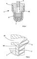
Figure 3 is a section through the foot portion shown inFigure 2 ; -
Figure 4 shows the foot portion ofFigures 2 and3 with an internal spring removed; and -
Figure 5 shows an enlarged detail of part of the foot portion shown inFigure 4 . -
Figure 1 shows a spectroscopic instrument 1, which in this embodiment is a Fourier Transform spectrometer with a scan mechanism that rotates back and forth around a vertical axis. The instrument comprises amain body 2 and has four supportingfoot portions 3 on its underside. Inside the main body of theinstrument 2 are the operative parts of the instrument including the scan mechanism as mentioned above. However, the detail of the structure and operation of the internal parts of the instrument 1 are not of any particular interest in relation to the present invention save for the fact that they need to be protected from vibration. Thus detailed drawings and description of the internal working components of the spectrometer 1 are omitted. It will be appreciated that thefoot portions 3, which are described in more detail below, could equally be used to protect other spectroscopic instruments with similar requirements for vibration isolation. -
Figure 2 shows one of thefoot portions 3, used to support the spectroscopic instrument 1 ofFigure 1 , in more detail andFigure 3 is a sectional view of thefoot portion 3 shown inFigure 2 . Theremaining foot portions 3 provided on the spectroscopic instrument 1, in the present embodiment, are the same as the foot portion shown inFigures 2 and3 . - Referring particularly to
Figure 3 , thefoot portion 3 comprises a stub portion 4 (which in this embodiment is of metal) to which is mounted a generally cup shapedelastomeric portion 5. Theelastomeric portion 5 is bonded with an adhesive to thestub portion 4. - The
stub portion 4 has aninternal bore 41. Thebore 41 runs along the axis of thestub portion 4 and passes through the whole of its length. A first end of thebore 41 is covered by theelastomeric portion 5 and a second end of thebore 41 is plugged with aplug 6 which, in this embodiment, is in the form of a set screw. - Together the
stub portion 4,elastomeric portion 5, andplug 6 form a sealed interior in thefoot portion 3. Liquid 7 is provided within this sealed region. - A
spring 8 is also provided within the interior of theelastomeric portion 5. Thespring 8 is shown in position inFigure 3 , butFigure 4 shows thefoot portion 3 with thespring 8 omitted.Figure 5 shows a detail of the foot portion as shown inFigure 4 again with the spring omitted. The spring is omitted fromFigures 4 and 5 partly for reasons of clarity. However, as an alternative to the present embodiment as shown inFigure 3 , it is possible to omit thespring 8 to form an alternative foot portion as illustrated inFigure 4 . - The
plug 6 projects from thestub portion 4 as shown inFigure 3 even when it is fully inserted into thestub 4 so as to seal the interior. A sealing medium, for example PTFE tape, is provided on the plug's 6 thread. The projecting portion of theplug 6 is used in mounting eachfoot portion 3 to themain body 2 of the spectroscopic instrument 1 as illustrated inFigure 1 . - The
stub portion 4 is generally cylindrical with thebore 41 running though its axis. However thestub portion 4 has portions of differing diameter such that its outer surface is stepped. A firstcylindrical portion 42 of thestub portion 4 is provided part way along its length and has a first external diameter which is larger than the external diameter of a secondcylindrical portion 43 and smaller than the external diameter of a third cylindrical portion (or lip) 44. - The first
cylindrical portion 42 can be considered a main body of the stub portion and theelastomeric portion 5 fits closely with the curved surface of this firstcylindrical portion 42 and is adhesively bonded to thelip 44. - The second
cylindrical portion 43 extends away from the firstcylindrical portion 42 into theelastomeric portion 5. Thebore 41 is of larger diameter along a substantial portion of this secondcylindrical portion 43 of thestub 4. Thislarger diameter portion 41a of thebore 41 serves to accommodate some of the liquid 7 provided in the foot portion to act as a reservoir and also accommodates the majority of thespring 8. - The
spring 8 is located within theenlarged portion 41a of theinternal bore 41 and attached to the stub portion in the enlarged portion of thebore 41 a. Whilst thespring 8 is attached to thestub portion 4 and guided within the enlarged portion of thebore 41 a, the other end of thespring 8 is not attached to theelastomeric portion 5, but rather simply bears on it. - The
elastomeric portion 5 has a firstcylindrical portion 51, a secondcylindrical portion 52 having a smaller internal (and external) diameter than that of the firstcylindrical portion 51, and a flaredportion 53 between these two portions. Further theelastomeric portion 5 has abase portion 54 which is arranged for contacting the surface on which the instrument 1 carrying thefoot portion 3 is to be stood. - The
elastomeric portion 5 is load bearing in the sense that it supports at least a proportion of the weight of the instrument 1. In the present embodiment, where thespring 8 is provided, thespring 8 will also bear a proportion of the weight of the instrument. In alternatives, as mentioned above, where thespring 8 is omitted, then theelastomeric portion 5 will bear all of the weight which is borne by thefoot portion 3. - Note in particular that the
foot portion 3 is constructed and arranged so that in normal usage the weight of the instrument 1 will not be borne through thestub portion 4. In particular it will not be borne through the secondcylindrical portion 43 of the stub portion. In other words the foot is arranged so that in normal usage theelastomeric member 5, and in particular thebase portion 54 of theelastomeric member 5, will not contact with the axial end of thestub portion 4. - The second
cylindrical portion 52 of theelastomeric member 5 is arranged so as to closely surround but be spaced from the secondcylindrical portion 43 of thestub portion 4. As such there is a spacing or gap G between the external wall of the second cylindrical portion of thestub portion 4 and the internal wall of the secondcylindrical portion 52 of theelastomeric portion 5. This gap G may be most clearly seen inFigure 5 . Again, as most clearly can be seen inFigure 5 , this annular spacing G is occupied to a predetermined depth (dependent upon the amount ofliquid 7 in the foot) by theliquid 7 when thefoot portion 3 is in its normal orientation for supporting the instrument 1. The liquid 7 in the reservoir, including that in the enlarged portion of thebore 41 a is free to flow into and out of the gap G via the open end of the enlarged portion of thebore 41 a. - A
vent aperture 45 is provided in thestub portion 4. Thevent aperture 45 is provided through the side wall of the secondcylindrical portion 43 of the stub portion such that there is a fluid communication path from above the liquid level in thebore 41 to above the liquid level in the region between thestub portion 4 andelastomeric member 5. - It will be appreciated that in use when the
elastomeric member 5 tends to move relative to thestub portion 4 due to vibrations and so on, then the existence of the liquid 7 in the spacing G will tend to damp such movement. Thevent aperture 45 serves to avoid any air lock problems occurring in the spacing G to ensure that this functionality is not inhibited. - It will also be noted that the second
cylindrical portion 43 of the (metal)stub portion 4 will be considerably more rigid than theelastomeric portion 5. Due to the spacing G, the stub portion 4 (in particular the secondcylindrical portion 43 of the stub portion 4) does not prevent transverse movement of the elastomeric portion 5 (in particular the secondcylindrical portion 52 and the base portion 54) relative to thestub portion 4 whilst these movements are small. However, any large movement which might otherwise take place (i.e. a movement greater than the spacing G) will be resisted and in normal circumstances prevented by the presence of the secondcylindrical portion 43 of thestub portion 4 extending down into theelastomeric portion 5. Thus the arrangement of thestub portion 4,elastomeric portion 5, and liquid 7 in the spacing therebetween serve to both damp vibrational movements which the foot portion may incur, and (in practical terms) prevent excessive translational movement which might otherwise occur for example when the instrument 1 is slid across the supporting surface. Accordingly these features can provide good damping by allowing theelastomeric material 5 to be soft to maximise the vibration protection delivered, whilst avoiding potentially hazardous or alarming wobbling of the instrument 1 during normal use and slumping offoot portions 3 during movement of the instrument 1. - As alluded to above, the end of the spring 8 (which is not mounted in the second
cylindrical portion 43 of the stub portion 4) bears against an internal axial surface of theelastomeric portion 5 at itsbase portion 54. This allows thespring 8 to provide some vertical load bearing assistance to help prevent theelastomeric portion 5 creeping and hence reducing in height over time. On the other hand the arrangement provides very little interference to the transverse or horizontal compliance of thefoot portion 3. This is largely due to the fact that thespring 8 tends not to resist such transverse movement to any large degree. - To assemble the foot portion shown in
Figure 3 , thespring 8 is first fitted into thebore 41 of thestub portion 4. Theelastomeric portion 5 is then fitted over the firstcylindrical portion 42 of the stub portion and glued at its end to the third cylindrical portion (or lip) 44. At this stage thefoot portion 3 is pressure tested to ensure the integrity of the seal. Following this, the interior of the foot portion, in particular thebore 41, is filled withliquid 7, such as high viscosity silicone fluid, up to a level just below thevent aperture 45. The plug (set screw) 6 is then inserted into the correspondingly tapped portion of thebore 41 and lockingly sealed with a thread lock of PTFE tape. At this stage thefoot portion 3 is complete and can be attached to the instrument 1 using the projecting portion of theplug 6. - As will be appreciated, the viscosity of the
liquid 7, softness of theelastomeric portion 5 and spacing G between theelastomeric portion 5 andstub portion 4 may be chosen to give different degrees of strength and vibration isolation characteristics. - Note that the flared design of the
elastomeric portion 5 helps to increase horizontal, or transverse, compliance of thefoot portion 3. In alternatives afoot portion 3 which is not flared in this way might be used. - In alternatives the stub portion may be of plastics material, which then may be a moulded plastics part. The plastics material would be chosen so as to be rigid compared to the elastomeric portion.
Claims (10)
- A load bearing anti-vibration foot portion (3) for mounting to a main body of a spectroscopic instrument for supporting the spectroscopic instrument on a surface, the foot portion (3) comprising a load bearing elastomeric portion (5) and an internal stub portion (4), the stub portion (4) being generally cylindrical having a first cylindrical portion (42) with a first external diameter and a second cylindrical portion (43) with a second, smaller, external diameter, the elastomeric portion (5) being generally cup shaped, and comprising a base portion (54) for contacting with a surface on which the instrument is to be supported, the stub portion being provided within the elastomeric portion (5) and being rigid compared to the elastomeric portion (5), wherein the elastomeric portion has a first hollow cylindrical portion (51) with a first internal diameter, a second hollow cylindrical portion (52) with a second, smaller, internal diameter and a flared portion (53) between the first and second cylindrical portions, and the first hollow cylindrical portion of the elastomeric portion (5) is mounted to the first cylindrical portion of the stub portion (4), the second cylindrical portion (43), of the stub portion (4) being further from the body of the instrument than the first portion and extending down into the elastomeric portion (5), wherein, an internal wall of the second hollow cylindrical portion (52) of the elastomeric portion (5) is spaced from an external wall of the second portion of the stub portion (4) such that the elastomeric portion (5) is moveable transversely relative to the second portion (43) of the stub portion to absorb vibration whilst presence of the second portion of the stub restricts transverse movement of the elastomeric portion and liquid is provided in the spacing between the internal wall of the elastomeric portion and the external wall of the stub portion to damp such movement.
- A load bearing anti-vibration foot portion according to claim 1 in which the foot portion comprises a load bearing spring (8) which is mounted to the stub (4) and provided within the elastomeric portion (5).
- A load bearing anti-vibration foot portion according to claim 2 in which an end of the spring (8) bears on an internal axial surface of the elastomeric portion (5).
- A load bearing anti-vibration foot portion according to any preceding claim in which the stub portion (4) and elastomeric portion (5) are dimensioned and arranged so as to resist lateral movement of the second portion (52) of the elastomeric portion relative to the first portion (51) of the elastomeric portion by a distance that is greater than said spacing between the internal wall of the elastomeric portion (5) and the external wall of the stub portion (4).
- A load bearing anti-vibration foot portion according to any preceding claim in which the stub portion (4) comprises an internal bore (41), at least part of which is occupied by at least part of a liquid reservoir.
- A load bearing anti-vibration foot portion according to claim 5 in which a vent aperture (45) is provided in the stub (4) which allows fluid communication between a region in the bore (41) of the stub which is above the level of the liquid (7) in the bore during normal operation and a region between the external wall of the stub portion (4) and the internal wall of the elastomeric portion (5) which is above the level of the liquid in the spacing between the external wall of the stub portion (4) and the internal wall of the elastomeric portion (5) during normal operation.
- A load bearing anti-vibration foot portion according to claim 5 or claim 6 in which the bore (41) provided in the stub portion (4) is a through bore, one end of the bore being covered by the elastomeric portion (5) and another end of the bore being blanked by a plug (6) which is inserted during assembly.
- A load bearing anti-vibration foot portion according to claim 7 in which the plug (6) also serves as a mounting for mounting the foot portion (3) to the main body of the instrument (1).
- A spectroscopic instrument (1) comprising at least one load bearing anti-vibration foot portion (3) according to any preceding claim.
- A method of making a spectroscopic instrument as claimed in claim 9 when dependent on any one of claims 5 to 8 or making a load bearing anti-vibration foot portion for mounting to a main body of a spectroscopic instrument as claimed in any one of claims 5 to 8, the method comprising the steps of:mounting the load bearing elastomeric portion (5) on the internal stub portion (4);introducing liquid (7) into the foot portion (3) through the bore (41) in the stub portion (4); andplugging an end of the bore (41) through which the liquid was introduced.
Applications Claiming Priority (2)
| Application Number | Priority Date | Filing Date | Title |
|---|---|---|---|
| GB1021578.8A GB2486499A (en) | 2010-12-17 | 2010-12-17 | Anti-vibration foot portions for spectroscopic instruments |
| PCT/GB2011/001675 WO2012080688A1 (en) | 2010-12-17 | 2011-12-01 | Spectroscopic instruments and foot portions for spectroscopic instruments |
Publications (2)
| Publication Number | Publication Date |
|---|---|
| EP2652468A1 EP2652468A1 (en) | 2013-10-23 |
| EP2652468B1 true EP2652468B1 (en) | 2016-08-24 |
Family
ID=43598674
Family Applications (1)
| Application Number | Title | Priority Date | Filing Date |
|---|---|---|---|
| EP11802120.3A Not-in-force EP2652468B1 (en) | 2010-12-17 | 2011-12-01 | Spectroscopic instruments and foot portions for spectroscopic instruments |
Country Status (4)
| Country | Link |
|---|---|
| US (1) | US9250127B2 (en) |
| EP (1) | EP2652468B1 (en) |
| GB (1) | GB2486499A (en) |
| WO (1) | WO2012080688A1 (en) |
Cited By (1)
| Publication number | Priority date | Publication date | Assignee | Title |
|---|---|---|---|---|
| DE102016118184B3 (en) * | 2016-09-27 | 2017-10-26 | Sartorius Lab Instruments Gmbh & Co. Kg | Use of a hydraulic shock absorber and laboratory device |
Families Citing this family (2)
| Publication number | Priority date | Publication date | Assignee | Title |
|---|---|---|---|---|
| US10716400B2 (en) * | 2017-10-18 | 2020-07-21 | Dell Products, L.P. | System and method for horizontal leveling of server racks |
| JP2022162656A (en) * | 2021-04-13 | 2022-10-25 | セイコーエプソン株式会社 | Color measuring device |
Family Cites Families (22)
| Publication number | Priority date | Publication date | Assignee | Title |
|---|---|---|---|---|
| US2597800A (en) * | 1948-09-13 | 1952-05-20 | Hussman Carl | Vibration isolation unit |
| US2896937A (en) * | 1957-09-13 | 1959-07-28 | Gen Tire & Rubber Co | Vibration isolator with variable damping |
| US3346221A (en) * | 1965-02-04 | 1967-10-10 | Sanders Associates Inc | Critically damped vibration system |
| FR2255508B1 (en) * | 1973-12-21 | 1976-10-08 | Vibrachoc Sa | |
| DE2727244C2 (en) * | 1976-06-30 | 1990-06-21 | Automobiles Peugeot, 75116 Paris | Rubber spring with liquid filling |
| ES274469Y (en) * | 1982-10-28 | 1984-08-16 | Continental Gummi-Werke Aktiengesellschaft | HYDRAULICALLY CUSHIONED ELASTIC SUPPORT, ESPECIALLY FOR THE PROPELLER MOTOR IN AUTOMOBILE VEHICLES |
| JPS6040843A (en) * | 1983-08-15 | 1985-03-04 | Bridgestone Corp | Orifice structure for vibration-proof device |
| DE8506373U1 (en) * | 1985-03-06 | 1985-05-09 | Klüsener, Roswitha, 4300 Essen | Device for damping vibrations |
| DE3815817A1 (en) * | 1988-05-09 | 1989-11-23 | Boge Ag | BEARINGS FOR THE ELASTIC BEARING OF MACHINES, MACHINE PARTS AND/OR VEHICLE PARTS |
| EP0669484B1 (en) * | 1994-02-15 | 1998-10-21 | FUKOKU Co., Ltd. | Fluid-filled mount |
| JP3526117B2 (en) * | 1994-11-07 | 2004-05-10 | 株式会社小松製作所 | Liquid filled suspension |
| DE4440392A1 (en) * | 1994-11-11 | 1996-05-15 | Wolf Woco & Co Franz J | Bearing for the damping arrangement of vibrating masses |
| DE19543239A1 (en) | 1995-11-20 | 1997-05-22 | Wolf Woco & Co Franz J | camp |
| US6455850B1 (en) * | 1998-08-14 | 2002-09-24 | Global Technovations, Inc. | On-site analyzer having spark emission spectrometer with even-wearing electrodes |
| US6439551B1 (en) * | 1999-08-10 | 2002-08-27 | Polymatech Co., Ltd. | Variable spring constant type damper filled with viscous fluid |
| KR20030085715A (en) * | 2002-05-01 | 2003-11-07 | 가부시키가이샤 후코쿠 | Fluid-filled mount |
| DE10359457A1 (en) * | 2003-12-17 | 2005-07-21 | Carl Freudenberg Kg | hydromount |
| KR100622500B1 (en) * | 2004-12-17 | 2006-09-19 | 현대자동차주식회사 | Engine mounting insulator |
| US20090014930A1 (en) * | 2005-11-15 | 2009-01-15 | Fukoku Co., Ltd | Liquid sealed mount and method of assembling the same |
| JP4854379B2 (en) * | 2006-05-02 | 2012-01-18 | ポリマテック株式会社 | Viscous fluid filled damper |
| CN101813154B (en) * | 2009-02-24 | 2013-02-13 | 仓敷化工株式会社 | Liquid-filled vibration isolator |
| IT1393550B1 (en) * | 2009-04-03 | 2012-04-27 | Lord Corp | FORK ELEVATOR WITH ANTI-VIBRATION DEVICE |
-
2010
- 2010-12-17 GB GB1021578.8A patent/GB2486499A/en not_active Withdrawn
-
2011
- 2011-12-01 EP EP11802120.3A patent/EP2652468B1/en not_active Not-in-force
- 2011-12-01 US US13/994,588 patent/US9250127B2/en active Active
- 2011-12-01 WO PCT/GB2011/001675 patent/WO2012080688A1/en not_active Ceased
Cited By (3)
| Publication number | Priority date | Publication date | Assignee | Title |
|---|---|---|---|---|
| DE102016118184B3 (en) * | 2016-09-27 | 2017-10-26 | Sartorius Lab Instruments Gmbh & Co. Kg | Use of a hydraulic shock absorber and laboratory device |
| WO2018059724A1 (en) | 2016-09-27 | 2018-04-05 | Sartorius Lab Instruments Gmbh & Co.Kg | Use of a hydraulic shock absorber and laboratory device |
| US10976192B2 (en) | 2016-09-27 | 2021-04-13 | Sartorius Lab Instruments Gmbh & Co., Kg | Hydraulic shock absorber and laboratory device |
Also Published As
| Publication number | Publication date |
|---|---|
| US20140125974A1 (en) | 2014-05-08 |
| GB201021578D0 (en) | 2011-02-02 |
| EP2652468A1 (en) | 2013-10-23 |
| GB2486499A (en) | 2012-06-20 |
| WO2012080688A1 (en) | 2012-06-21 |
| US9250127B2 (en) | 2016-02-02 |
Similar Documents
| Publication | Publication Date | Title |
|---|---|---|
| JP2008138854A (en) | Liquid seal vibration isolator | |
| US9250127B2 (en) | Spectroscopic instruments and foot portions for spectroscopic instruments | |
| EP2894370B1 (en) | Liquid filled mount | |
| WO2018051627A1 (en) | Anti-vibration device | |
| EP2728218A1 (en) | Vibration isolator | |
| JP4740721B2 (en) | Viscous fluid filled damper | |
| EP2685126A1 (en) | Anti-vibration device | |
| JP5668231B2 (en) | Liquid-filled vibration isolator | |
| JP2008539385A (en) | Magnetic bearings for damping or isolation systems | |
| JP6391162B2 (en) | Vibration isolator | |
| JP2016008709A (en) | Vibration prevention device | |
| JP5406702B2 (en) | Liquid filled vibration isolator | |
| JP5275884B2 (en) | Liquid filled vibration isolator | |
| JP4767091B2 (en) | Liquid filled anti-vibration mount | |
| JP6431262B2 (en) | Liquid filled vibration isolator | |
| JP4794501B2 (en) | Liquid filled anti-vibration support device | |
| JP5899039B2 (en) | Fluid filled vibration isolator | |
| JP2009144844A (en) | Vibration control device | |
| JP2009257442A (en) | Viscous fluid-filled damper | |
| JPH04370438A (en) | Vibration control device | |
| JP2014169775A (en) | Vibration-proofing device | |
| JP2023160206A (en) | Vibration isolator | |
| JP2013217403A (en) | Liquid-sealed vibration control device | |
| JP2008128368A (en) | Vibration control device | |
| JP6404616B2 (en) | Vibration isolator |
Legal Events
| Date | Code | Title | Description |
|---|---|---|---|
| PUAI | Public reference made under article 153(3) epc to a published international application that has entered the european phase |
Free format text: ORIGINAL CODE: 0009012 |
|
| 17P | Request for examination filed |
Effective date: 20130628 |
|
| AK | Designated contracting states |
Kind code of ref document: A1 Designated state(s): AL AT BE BG CH CY CZ DE DK EE ES FI FR GB GR HR HU IE IS IT LI LT LU LV MC MK MT NL NO PL PT RO RS SE SI SK SM TR |
|
| DAX | Request for extension of the european patent (deleted) | ||
| 17Q | First examination report despatched |
Effective date: 20140409 |
|
| GRAP | Despatch of communication of intention to grant a patent |
Free format text: ORIGINAL CODE: EPIDOSNIGR1 |
|
| INTG | Intention to grant announced |
Effective date: 20160324 |
|
| GRAS | Grant fee paid |
Free format text: ORIGINAL CODE: EPIDOSNIGR3 |
|
| GRAA | (expected) grant |
Free format text: ORIGINAL CODE: 0009210 |
|
| AK | Designated contracting states |
Kind code of ref document: B1 Designated state(s): AL AT BE BG CH CY CZ DE DK EE ES FI FR GB GR HR HU IE IS IT LI LT LU LV MC MK MT NL NO PL PT RO RS SE SI SK SM TR |
|
| REG | Reference to a national code |
Ref country code: GB Ref legal event code: FG4D |
|
| REG | Reference to a national code |
Ref country code: CH Ref legal event code: EP |
|
| REG | Reference to a national code |
Ref country code: AT Ref legal event code: REF Ref document number: 823520 Country of ref document: AT Kind code of ref document: T Effective date: 20160915 |
|
| REG | Reference to a national code |
Ref country code: IE Ref legal event code: FG4D |
|
| REG | Reference to a national code |
Ref country code: DE Ref legal event code: R096 Ref document number: 602011029673 Country of ref document: DE |
|
| REG | Reference to a national code |
Ref country code: LT Ref legal event code: MG4D |
|
| REG | Reference to a national code |
Ref country code: NL Ref legal event code: MP Effective date: 20160824 |
|
| REG | Reference to a national code |
Ref country code: AT Ref legal event code: MK05 Ref document number: 823520 Country of ref document: AT Kind code of ref document: T Effective date: 20160824 |
|
| PG25 | Lapsed in a contracting state [announced via postgrant information from national office to epo] |
Ref country code: HR Free format text: LAPSE BECAUSE OF FAILURE TO SUBMIT A TRANSLATION OF THE DESCRIPTION OR TO PAY THE FEE WITHIN THE PRESCRIBED TIME-LIMIT Effective date: 20160824 Ref country code: IT Free format text: LAPSE BECAUSE OF FAILURE TO SUBMIT A TRANSLATION OF THE DESCRIPTION OR TO PAY THE FEE WITHIN THE PRESCRIBED TIME-LIMIT Effective date: 20160824 Ref country code: RS Free format text: LAPSE BECAUSE OF FAILURE TO SUBMIT A TRANSLATION OF THE DESCRIPTION OR TO PAY THE FEE WITHIN THE PRESCRIBED TIME-LIMIT Effective date: 20160824 Ref country code: LT Free format text: LAPSE BECAUSE OF FAILURE TO SUBMIT A TRANSLATION OF THE DESCRIPTION OR TO PAY THE FEE WITHIN THE PRESCRIBED TIME-LIMIT Effective date: 20160824 Ref country code: NL Free format text: LAPSE BECAUSE OF FAILURE TO SUBMIT A TRANSLATION OF THE DESCRIPTION OR TO PAY THE FEE WITHIN THE PRESCRIBED TIME-LIMIT Effective date: 20160824 Ref country code: FI Free format text: LAPSE BECAUSE OF FAILURE TO SUBMIT A TRANSLATION OF THE DESCRIPTION OR TO PAY THE FEE WITHIN THE PRESCRIBED TIME-LIMIT Effective date: 20160824 Ref country code: NO Free format text: LAPSE BECAUSE OF FAILURE TO SUBMIT A TRANSLATION OF THE DESCRIPTION OR TO PAY THE FEE WITHIN THE PRESCRIBED TIME-LIMIT Effective date: 20161124 |
|
| PG25 | Lapsed in a contracting state [announced via postgrant information from national office to epo] |
Ref country code: GR Free format text: LAPSE BECAUSE OF FAILURE TO SUBMIT A TRANSLATION OF THE DESCRIPTION OR TO PAY THE FEE WITHIN THE PRESCRIBED TIME-LIMIT Effective date: 20161125 Ref country code: LV Free format text: LAPSE BECAUSE OF FAILURE TO SUBMIT A TRANSLATION OF THE DESCRIPTION OR TO PAY THE FEE WITHIN THE PRESCRIBED TIME-LIMIT Effective date: 20160824 Ref country code: ES Free format text: LAPSE BECAUSE OF FAILURE TO SUBMIT A TRANSLATION OF THE DESCRIPTION OR TO PAY THE FEE WITHIN THE PRESCRIBED TIME-LIMIT Effective date: 20160824 Ref country code: SE Free format text: LAPSE BECAUSE OF FAILURE TO SUBMIT A TRANSLATION OF THE DESCRIPTION OR TO PAY THE FEE WITHIN THE PRESCRIBED TIME-LIMIT Effective date: 20160824 Ref country code: AT Free format text: LAPSE BECAUSE OF FAILURE TO SUBMIT A TRANSLATION OF THE DESCRIPTION OR TO PAY THE FEE WITHIN THE PRESCRIBED TIME-LIMIT Effective date: 20160824 Ref country code: PT Free format text: LAPSE BECAUSE OF FAILURE TO SUBMIT A TRANSLATION OF THE DESCRIPTION OR TO PAY THE FEE WITHIN THE PRESCRIBED TIME-LIMIT Effective date: 20161226 |
|
| PG25 | Lapsed in a contracting state [announced via postgrant information from national office to epo] |
Ref country code: EE Free format text: LAPSE BECAUSE OF FAILURE TO SUBMIT A TRANSLATION OF THE DESCRIPTION OR TO PAY THE FEE WITHIN THE PRESCRIBED TIME-LIMIT Effective date: 20160824 Ref country code: RO Free format text: LAPSE BECAUSE OF FAILURE TO SUBMIT A TRANSLATION OF THE DESCRIPTION OR TO PAY THE FEE WITHIN THE PRESCRIBED TIME-LIMIT Effective date: 20160824 |
|
| REG | Reference to a national code |
Ref country code: DE Ref legal event code: R097 Ref document number: 602011029673 Country of ref document: DE |
|
| PG25 | Lapsed in a contracting state [announced via postgrant information from national office to epo] |
Ref country code: SK Free format text: LAPSE BECAUSE OF FAILURE TO SUBMIT A TRANSLATION OF THE DESCRIPTION OR TO PAY THE FEE WITHIN THE PRESCRIBED TIME-LIMIT Effective date: 20160824 Ref country code: DK Free format text: LAPSE BECAUSE OF FAILURE TO SUBMIT A TRANSLATION OF THE DESCRIPTION OR TO PAY THE FEE WITHIN THE PRESCRIBED TIME-LIMIT Effective date: 20160824 Ref country code: BG Free format text: LAPSE BECAUSE OF FAILURE TO SUBMIT A TRANSLATION OF THE DESCRIPTION OR TO PAY THE FEE WITHIN THE PRESCRIBED TIME-LIMIT Effective date: 20161124 Ref country code: CZ Free format text: LAPSE BECAUSE OF FAILURE TO SUBMIT A TRANSLATION OF THE DESCRIPTION OR TO PAY THE FEE WITHIN THE PRESCRIBED TIME-LIMIT Effective date: 20160824 Ref country code: SM Free format text: LAPSE BECAUSE OF FAILURE TO SUBMIT A TRANSLATION OF THE DESCRIPTION OR TO PAY THE FEE WITHIN THE PRESCRIBED TIME-LIMIT Effective date: 20160824 Ref country code: PL Free format text: LAPSE BECAUSE OF FAILURE TO SUBMIT A TRANSLATION OF THE DESCRIPTION OR TO PAY THE FEE WITHIN THE PRESCRIBED TIME-LIMIT Effective date: 20160824 Ref country code: BE Free format text: LAPSE BECAUSE OF FAILURE TO SUBMIT A TRANSLATION OF THE DESCRIPTION OR TO PAY THE FEE WITHIN THE PRESCRIBED TIME-LIMIT Effective date: 20160824 |
|
| PLBE | No opposition filed within time limit |
Free format text: ORIGINAL CODE: 0009261 |
|
| STAA | Information on the status of an ep patent application or granted ep patent |
Free format text: STATUS: NO OPPOSITION FILED WITHIN TIME LIMIT |
|
| REG | Reference to a national code |
Ref country code: CH Ref legal event code: PL |
|
| 26N | No opposition filed |
Effective date: 20170526 |
|
| PG25 | Lapsed in a contracting state [announced via postgrant information from national office to epo] |
Ref country code: SI Free format text: LAPSE BECAUSE OF FAILURE TO SUBMIT A TRANSLATION OF THE DESCRIPTION OR TO PAY THE FEE WITHIN THE PRESCRIBED TIME-LIMIT Effective date: 20160824 |
|
| PG25 | Lapsed in a contracting state [announced via postgrant information from national office to epo] |
Ref country code: MC Free format text: LAPSE BECAUSE OF FAILURE TO SUBMIT A TRANSLATION OF THE DESCRIPTION OR TO PAY THE FEE WITHIN THE PRESCRIBED TIME-LIMIT Effective date: 20160824 |
|
| REG | Reference to a national code |
Ref country code: FR Ref legal event code: ST Effective date: 20170831 |
|
| REG | Reference to a national code |
Ref country code: IE Ref legal event code: MM4A |
|
| PG25 | Lapsed in a contracting state [announced via postgrant information from national office to epo] |
Ref country code: LU Free format text: LAPSE BECAUSE OF NON-PAYMENT OF DUE FEES Effective date: 20161201 Ref country code: LI Free format text: LAPSE BECAUSE OF NON-PAYMENT OF DUE FEES Effective date: 20161231 Ref country code: CH Free format text: LAPSE BECAUSE OF NON-PAYMENT OF DUE FEES Effective date: 20161231 Ref country code: FR Free format text: LAPSE BECAUSE OF NON-PAYMENT OF DUE FEES Effective date: 20170102 |
|
| PG25 | Lapsed in a contracting state [announced via postgrant information from national office to epo] |
Ref country code: IE Free format text: LAPSE BECAUSE OF NON-PAYMENT OF DUE FEES Effective date: 20161201 |
|
| PG25 | Lapsed in a contracting state [announced via postgrant information from national office to epo] |
Ref country code: CY Free format text: LAPSE BECAUSE OF FAILURE TO SUBMIT A TRANSLATION OF THE DESCRIPTION OR TO PAY THE FEE WITHIN THE PRESCRIBED TIME-LIMIT Effective date: 20160824 Ref country code: HU Free format text: LAPSE BECAUSE OF FAILURE TO SUBMIT A TRANSLATION OF THE DESCRIPTION OR TO PAY THE FEE WITHIN THE PRESCRIBED TIME-LIMIT; INVALID AB INITIO Effective date: 20111201 |
|
| PG25 | Lapsed in a contracting state [announced via postgrant information from national office to epo] |
Ref country code: IS Free format text: LAPSE BECAUSE OF FAILURE TO SUBMIT A TRANSLATION OF THE DESCRIPTION OR TO PAY THE FEE WITHIN THE PRESCRIBED TIME-LIMIT Effective date: 20160824 Ref country code: MK Free format text: LAPSE BECAUSE OF FAILURE TO SUBMIT A TRANSLATION OF THE DESCRIPTION OR TO PAY THE FEE WITHIN THE PRESCRIBED TIME-LIMIT Effective date: 20160824 |
|
| PG25 | Lapsed in a contracting state [announced via postgrant information from national office to epo] |
Ref country code: MT Free format text: LAPSE BECAUSE OF NON-PAYMENT OF DUE FEES Effective date: 20161201 |
|
| PG25 | Lapsed in a contracting state [announced via postgrant information from national office to epo] |
Ref country code: TR Free format text: LAPSE BECAUSE OF FAILURE TO SUBMIT A TRANSLATION OF THE DESCRIPTION OR TO PAY THE FEE WITHIN THE PRESCRIBED TIME-LIMIT Effective date: 20160824 Ref country code: AL Free format text: LAPSE BECAUSE OF FAILURE TO SUBMIT A TRANSLATION OF THE DESCRIPTION OR TO PAY THE FEE WITHIN THE PRESCRIBED TIME-LIMIT Effective date: 20160824 |
|
| PGFP | Annual fee paid to national office [announced via postgrant information from national office to epo] |
Ref country code: GB Payment date: 20221020 Year of fee payment: 12 Ref country code: DE Payment date: 20221018 Year of fee payment: 12 |
|
| P01 | Opt-out of the competence of the unified patent court (upc) registered |
Effective date: 20230601 |
|
| REG | Reference to a national code |
Ref country code: DE Ref legal event code: R119 Ref document number: 602011029673 Country of ref document: DE |
|
| GBPC | Gb: european patent ceased through non-payment of renewal fee |
Effective date: 20231201 |
|
| PG25 | Lapsed in a contracting state [announced via postgrant information from national office to epo] |
Ref country code: DE Free format text: LAPSE BECAUSE OF NON-PAYMENT OF DUE FEES Effective date: 20240702 |
|
| PG25 | Lapsed in a contracting state [announced via postgrant information from national office to epo] |
Ref country code: GB Free format text: LAPSE BECAUSE OF NON-PAYMENT OF DUE FEES Effective date: 20231201 |
|
| PG25 | Lapsed in a contracting state [announced via postgrant information from national office to epo] |
Ref country code: GB Free format text: LAPSE BECAUSE OF NON-PAYMENT OF DUE FEES Effective date: 20231201 Ref country code: DE Free format text: LAPSE BECAUSE OF NON-PAYMENT OF DUE FEES Effective date: 20240702 |