EP2652435B1 - A mine detonating apparatus and a method of steering the same - Google Patents
A mine detonating apparatus and a method of steering the same Download PDFInfo
- Publication number
- EP2652435B1 EP2652435B1 EP11808287.4A EP11808287A EP2652435B1 EP 2652435 B1 EP2652435 B1 EP 2652435B1 EP 11808287 A EP11808287 A EP 11808287A EP 2652435 B1 EP2652435 B1 EP 2652435B1
- Authority
- EP
- European Patent Office
- Prior art keywords
- vehicle
- mine detonating
- ground engaging
- detonating apparatus
- mine
- Prior art date
- Legal status (The legal status is an assumption and is not a legal conclusion. Google has not performed a legal analysis and makes no representation as to the accuracy of the status listed.)
- Active
Links
Images



Classifications
-
- F—MECHANICAL ENGINEERING; LIGHTING; HEATING; WEAPONS; BLASTING
- F41—WEAPONS
- F41H—ARMOUR; ARMOURED TURRETS; ARMOURED OR ARMED VEHICLES; MEANS OF ATTACK OR DEFENCE, e.g. CAMOUFLAGE, IN GENERAL
- F41H11/00—Defence installations; Defence devices
- F41H11/12—Means for clearing land minefields; Systems specially adapted for detection of landmines
- F41H11/16—Self-propelled mine-clearing vehicles; Mine-clearing devices attachable to vehicles
- F41H11/30—Self-propelled mine-clearing vehicles; Mine-clearing devices attachable to vehicles with rollers creating a surface load on the ground, e.g. steadily increasing surface load, for triggering purposes
Definitions
- the present invention relates to a mine detonating apparatus and in particular to a mine detonating apparatus mountable to a vehicle and adapted to automatically steer along a path that is subsequently driven over by the vehicle. Furthermore, the present invention relates to a method of operating a mine detonating apparatus, and in particular to a method of operating a mine detonating apparatus to automatically steer along a path subsequently driven over by the vehicle.
- rollers of the mine detonating apparatus trigger the explosion ahead of the vehicle, thereby minimising damage to the vehicle and potential injuries to the passengers.
- the mine detonating apparatus provides maximum protection to the vehicle, it is important that it can be steered such that when the vehicle is traversing a corner or around a bend, the rollers of the mine detonating apparatus roll over the ground surface that is subsequently driven over by the vehicle, therefore minimising the risk of the vehicle setting off an explosion and potentially causing significant damage to the vehicle and/or injury to an occupant.
- the mine detonating apparatus includes, inter alia, a front roller assembly 1 pivotably mounted to the front of the vehicle body 2 and a rear roller assembly 3 pivotably mounted to the rear of the vehicle body 2 .
- the rotation of the front roller assembly 1 about its pivotable mount 4 is controlled by a pair of hydraulic cylinders 5 connected to the front roller assembly 1 and the vehicle body 2 .
- the rotation of the rear roller assembly 3 about its pivotable mount 6 drives a pair of hydraulic cylinders 7 connected to the rear roller 3 assembly and the vehicle body 2 .
- the trailing rear roller assembly 3 swings to the inside of the turn, thereby compressing and extending respective rear hydraulic cylinders 7 .
- These hydraulic cylinders 7 are connected via hydraulic hoses (not shown) to the front cylinders 5 .
- the hydraulic forces generated in the front cylinders 5 steer the front roller assembly 1 to the inside of the turn.
- this arrangement has the disadvantage of requiring the presence of a rear roller assembly, which is unpractical for some vehicle types.
- the arrangement has a fixed relationship between the angle of the front roller assembly to that of the rear roller assembly. Therefore, depending on the geometry of the vehicle and the mine detonating apparatus, the relationship between the front steer angle and the rear castor angle may vary in a linear or non-linear manner.
- a further known apparatus comprises a control system which uses the castor angle of a rear roller system as an input signal to a control system which independently steers the front roller assembly accordingly utilising front cylinders.
- the disclosed mine detonating apparatus 8 includes two roller assemblies 9a, 9b that are pushed in front of a vehicle 10 by means of a frame 11 which is pivotably mounted to the vehicle 10.
- the frame 11 includes various linkages 12 and a hydraulic actuator 13 which allow the roller assemblies 9a, 9b to be steered relative to the frame 11.
- the various linkages 12 provide a mechanical feedback mechanism that allows the roller assemblies 9a, 9b to steer such that the frame 11 is moved to or maintained at a specified angle relative to the vehicle 10.
- the length of the hydraulic actuator specifies the angle of the frame relative to the vehicle.
- the mine detonating apparatus 8 described in GB2461155B comprises an electronic control system (not shown) which receives a signal from a transducer (not shown) coupled to the steering mechanism of the vehicle 10 and which determines an angle of the frame 11 relative to the vehicle 10 required to move the roller assemblies 9a, 9b along a path that is assumed to be subsequently driven over by the vehicle 10. The control system then sets the length of the hydraulic actuator 13 to the length required to provide the determined angle between the frame 11 and the vehicle 10.
- this arrangement has the disadvantage that the degree of steer applied to the mine detonating apparatus is determined by the angle of the steering mechanism of the vehicle.
- the relationship between the angle of the steering mechanism of the vehicle and the actual radius of the turn being traversed is inconsistent, especially on low friction surfaces such as soft sand.
- the geometry of the frame and the various linkages disclosed in GB2461155B must be individually designed for each specific vehicle geometry, making it impossible to swap the same mine detonating apparatus between different vehicle types.
- the pivotably mounted frame is inherently unstable and the mine detonating apparatus includes various linkages that provide mechanical feedback steering the roller assemblies in order to keep the frame at a specified angle and therefore overcome its instability. Consequently, depending on the degree of friction between the roller assemblies and the ground, the steered roller assemblies may not be able to apply sufficient force to keep the frame at the specified angle. Additionally, the roller assemblies may need to operate at a continuous slip angle in order to maintain the required position of the pivotably mounted frame, except in special cases. However, this will subsequently lead to accelerated wear of the roller tyres.
- a mine detonating apparatus for a vehicle comprising:
- the mine detonating apparatus may further comprise a second actuator means adapted to move the ground engaging means relative to the frame structure about a second axis substantially vertical relative to the ground, wherein the controller means may further be configured to selectively operate the first actuator means and/or the second actuator means in accordance with a difference between the actual position and the desired position of the apparatus to move the apparatus such that the ground engaging means cover a path subsequently driven over by the vehicle.
- the mine detonating apparatus in accordance with the present invention automatically ensures that the ground engaging means always cover the ground the vehicle subsequently drives over at minimal energy expenditure, irrespective of the vehicles intended steered direction, which may be different to the actual direction taken by the vehicle due to the profile and/or composition of the ground surface.
- the controller continuously determines the actual path of the vehicle and determines a desired position of the mine detonating apparatus relative to the vehicle.
- the desired position is the position of the mine detonating apparatus relative to the vehicle that ensures that the mine detonating apparatus follows the path subsequently driven over by the vehicle.
- the desired position of the mine detonating apparatus is then compared to its actual position, which is determined from a first feedback signal, for example, the angle of the frame structure with respect to the vehicle.
- first and/or second actuator means are used to move the mine detonating apparatus into the desired position.
- first actuator means and/or second actuator means may be operated to automatically steer and re-align the apparatus with the vehicle.
- the transducer means may be further adapted to provide a second feedback signal related to the position of the ground engaging means relative to the frame structure.
- the input signal may comprise the first and second feedback signals.
- the mine detonating apparatus may further comprise any one or more of a Global Positioning System (GPS) sensor operatively coupled to the mine detonating apparatus and/or the vehicle, an accelerometer operatively coupled to the mine detonating apparatus and/or the vehicle, and an inertial navigation system operatively coupled to the mine detonating apparatus and/or vehicle.
- GPS Global Positioning System
- the input signal may comprise a third feedback signal received from any one or more of the GPS sensor, the accelerometer and/or the inertial navigation system.
- a GPS sensor may provide a more accurate measure of the curvature of the vehicle path than determining the actual path from the first and second feedback signals alone. This would be desirable, for example, where the surface being driven over was uneven and undesirable 'noise' was being created in the system which could lead to inaccuracies.
- the ground engaging means may comprise one or more ground engaging members.
- the ground engaging members may comprise, for example, wheels, tracks or rollers.
- the ground engaging means comprises two spaced apart ground engaging roller assemblies. This provides the advantage that the mine detonating apparatus can cover sufficient width over the ground.
- the width of ground covered by the spaced apart ground engaging means is the same or more than the width covered by the vehicle wheels or tracks.
- each roller assembly is pivotably mounted to the frame structure to rotate about the second axis.
- the first and/or second actuator means may comprise one or more hydraulically and/or electrically driven actuators.
- the second actuator means comprises two second actuators each of which are operatively coupled to a ground engaging roller assembly.
- the second actuator means are smaller in size relative to the first actuator means.
- a plurality of ground engaging members allows for each ground engaging member to be relatively small.
- allowing the apparatus to be automatically steered by one or both of the second actuators provides an energy efficient apparatus as lower loads are required to operate the ground engaging members compared to operating the first actuator means to move the frame structure.
- the controller may selectively utilise only one of the second actuators of either one of the ground engaging members, whilst the remaining actuators (the other of the second actuator means and the first actuator means) are disengaged or allowed to 'float', therefore minimising the energy required to initially align the mine detonating apparatus.
- controller, first and second actuator means and transducer means form a control loop that allows for constant automatic alignment of the mine detonating apparatus relative to the vehicle to ensure the ground engaging means cover a path subsequently followed by the vehicle.
- the actual position of the mine detonating apparatus relative to the vehicle is optimised and aligned towards the desired position determined from the actual path of the vehicle.
- controller means may be adapted to selectively lock at least one of the first and second actuator means to lock the frame structure and/or ground engaging means in a predetermined position.
- the controller means may be adapted to selectively disengage at least one of the first actuator means and second actuator means to allow the frame structure and/or ground engaging means to move freely about its respective first and/or second axis.
- the ground engaging means will follow a natural path determined by the alignment of the frame structure relative to the vehicle, and also by the ground surface condition and the speed of the vehicle. Hence, excessive wear on the ground engaging means is avoided and the feedback from the disengaged ground engaging means may be used to determine any slippage in order to optimise the steering of the mine detonating apparatus.
- controller means may be adapted to receive, store and process computer readable instructions for operating the first and/or second actuator means.
- a typical sequence of operating the first and/or second actuator means may be programmed and executed by the controller.
- the controller may execute a standard sequence of which the first and/or second actuator means are disengaged or locked in a predetermined position to facilitate the steering of the vehicle when reversing.
- the transducer means comprises at least one first sensor operatively coupled to the frame structure.
- the transducer means further comprises at least one second sensor operatively coupled to the ground engaging means.
- the transducer means may comprise at least one goniometric sensor or at least one displacement sensor.
- the frame structure may be adapted to be mountable to the front of the vehicle with respect to the moving direction of the vehicle.
- a method for operating a mine detonating apparatus as herein described above mounted to a host vehicle comprises the steps of:
- step (v) the first and/or a second actuator means may be selectively operated in accordance with the difference between the actual position and the desired position of the apparatus relative to the vehicle to move the apparatus such that the ground engaging means cover a path subsequently driven over by the vehicle.
- the method may further comprise the step of selectively disengaging and/or locking any one of the first and/or second actuator means.
- a disengaged roller assembly of the mine detonating apparatus provides not only the advantage of minimising energy expenditure, but also that the radius of the actual path of the vehicle can be determined through, for example, a disengaged roller assembly of the mine detonating apparatus.
- a disengaged second actuator not only allows the roller assembly to run freely to follow a natural path that depends on the alignment of the frame structure, but also a path that depends on the ground surface condition as well as the speed of the host vehicle.
- slippage of the rollers may be reduced which in turn desirably minimises wear of the rollers.
- the step of determining the actual path of the vehicle and apparatus may be based on the first and second feedback signal and a dimension of the frame structure and/or the host vehicle.
- the path of the host vehicle may be determined based on a third feedback signal received from any one of at least one GPS sensor operatively coupled to the host vehicle, one or more accelerometers operatively coupled to either the frame structure and/or the host vehicle, and at least one inertial navigation system operatively coupled to the host vehicle.
- the method may further comprise the steps of processing a pre-programmed computer readable instruction and selectively operating the first and/or second actuator means in accordance to a predetermined operating sequence.
- a mine detonating apparatus 100 comprises a frame 120 adapted to be pivotably mounted to a vehicle 150 about an axis 160 and two spaced apart roller assemblies 130, 140, pivotably mounted to the frame 120 about their respective axes 170, 180.
- the frame 120 can pivot about the axis 160 in order to vary an angle ⁇ between the longitudinal axis of the frame 120 and the vehicle 150.
- the roller assemblies 130, 140 can pivot about their respective axes 170, 180 in order to vary an angle ⁇ L or ⁇ R between a longitudinal axis of each roller assembly 130, 140 and the frame 120.
- Each roller assembly 130, 140 is able to rotate through a full 360°.
- the roller assemblies 130, 140 are arranged to apply pressure to the ground in front of the vehicle 150.
- the mine detonating apparatus 100 also includes actuators in the form of, for example, two frame cylinders 190a, 190b between the frame 120 and the vehicle 150, which can be configured to be disengaged or "float", such that the frame 120 is free to rotate about its pivot axis 160, lock, such that the angle ⁇ remains fixed once the frame has been moved into position, or engage, i.e. one frame cylinder 190a extends/retracts while the other frame cylinder 190b retracts/extends, such that the angle ⁇ increases or decreases, respectively.
- actuators in the form of, for example, two frame cylinders 190a, 190b between the frame 120 and the vehicle 150, which can be configured to be disengaged or "float", such that the frame 120 is free to rotate about its pivot axis 160, lock, such that the angle ⁇ remains fixed once the frame has been moved into position, or engage, i.e. one frame cylinder 190a extends/retracts while the other frame cylinder 190b
- the mine detonating apparatus 100 also includes two castor cylinders 200a, 200b disposed between each roller assembly 130, 140, and the frame structure 120, wherein each of the castor cylinders 200a, 200b can be independently configured to either "float", such that their respective roller assemblies 130, 140 are free to rotate about their respective axes 170, 180, lock, such that angles ⁇ L and/or ⁇ R are fixed, or engage, i.e. extend or retract such that respective angles ⁇ L and/or ⁇ R increase or decrease with respect to the frame structure 120.
- the distance between a centre of rotation 210 of the vehicle 150 and the pivot axis 160 of the frame 120 is defined as length L V .
- the length of the frame 120 is defined as length L R .
- ⁇ L and ⁇ R are affected. This needs to be taken into account when calculating R. For example, if ⁇ is increasing, ⁇ L and ⁇ R will be larger than would be the case in the steady state.
- the mine detonating apparatus 100 further comprises a control system 220 that receives an input signal relating to an actual path of the vehicle 150.
- the control system 220 continuously receives the input signal relating to the actual path of the vehicle and continuously determines the current desired position of the mine detonating apparatus 100.
- the control system 220 compares the desired with the actual position of the mine detonating apparatus 100 relative to the vehicle 150 and operates any one of the frame cylinders 190a, 190b or castor cylinder 200a, 200b to move the frame 120 into the desired position.
- the actual position of the mine detonating apparatus 100 relative to the vehicle 150 is determined, for example, from the actual rotation angle ⁇ determined by respective transducer 229, which may be a goniometer or displacement sensor mounted on the axis 160.
- the input signal used to determine the actual path of the vehicle 150 may comprise the first and second feedback signals 330, 310, 320 relating to the actual rotation angles ⁇ , ⁇ L and ⁇ R from respective transducers 229, 230a, 230b.
- the inputs other than ⁇ , ⁇ L and ⁇ R may be used to determine the actual path of the vehicle 150 may comprise a third feedback signal (not shown) received from, for example, a Global Positioning System (GPS) sensor (not shown), one or more accelerometers (not shown) and/or an inertial navigation system (not shown).
- GPS Global Positioning System
- the GPS may be mounted to the vehicle 150 or frame structure 120.
- the accelerometers and inertial navigation system may be mounted to the vehicle 150 and/or frame 120.
- the frame cylinders 190a, 190b may be locked and the castor cylinders 200a, 200b may be free to 'float' such that the roller assemblies 130, 140 are free to follow a natural path determined by the angle of the frame structure 120 relative to the vehicle.
- the actual steer angle ⁇ of the frame 120 may be adjusted by disengaging the frame cylinders 190a, 190b and one of the castor cylinders 200a or 200b, such that the frame 120 and one of the roller assemblies 130 or 140 are free to "float" about their respective axes 160, 170, 180, wherein the other castor cylinder 200a or 200b is engaged by the controller 220.
- the angle ⁇ R or ⁇ L is varied such that the frame 120 tracks to the specified angle ⁇ s as the vehicle 150 advances, the frame cylinders 190a and 190b are then locked to fix the angle ⁇ , and the engaged castor cylinder 200a or 200b is disengaged to its "float" configuration.
- Which castor cylinder 200a or 200b is chosen to carry out the steer operation depends on the actual angle ⁇ , the desired angle ⁇ s and the actual turning radius R of the vehicle.
- the roller assembly which is able to generate the greatest torque for moving the apparatus is chosen to perform the steer operation. For example, when ⁇ is positive and it is desired to decrease ⁇ , the left hand roller assembly 130 should be engaged and if it is desired to increase ⁇ , the right hand roller assembly 140 should be used to perform the steering operation. The opposite is the case when ⁇ is negative.
- the actual steer angle ⁇ of the frame 120 may be adjusted by disengaging the castor cylinders 200a and 200b, such that the roller assemblies 130 and 140 are free to "float" about their respective axes 170 and 180, and the frame cylinders 190a, 190b are engaged by the controller 220 to steer the frame structure 120 until the desired angle ⁇ s is achieved.
- the mine detonating apparatus is steered using one of the castor cylinders 200a, 200b rather than the frame cylinders 190a, 190b, to desirably utilise the tractive effort of the vehicle instead of solely using electrical power as would be the case when steering using the frame cylinder 190a, 190b.
- the castor cylinders 200a, 200b When reversing the vehicle 150, the castor cylinders 200a, 200b may be disengaged such that the roller assemblies 130, 140 are free to "float" about their respective axes 170, 180.
- the frame cylinders 190a, 190b may either be disengaged to freely rotate about its axis 160, or locked in a specified position.
- Configuring the mine detonating device 100 for reversing can either be carried out manually or automatically by providing a pre-programmed operation sequence to the control system 220, such that the control system 220 executes a specific reversing procedure when 90° ⁇ ⁇ L ⁇ 270° and/or 90° ⁇ ⁇ R ⁇ 270°.
Landscapes
- Engineering & Computer Science (AREA)
- General Engineering & Computer Science (AREA)
- Control Of Position, Course, Altitude, Or Attitude Of Moving Bodies (AREA)
Description
- The present invention relates to a mine detonating apparatus and in particular to a mine detonating apparatus mountable to a vehicle and adapted to automatically steer along a path that is subsequently driven over by the vehicle. Furthermore, the present invention relates to a method of operating a mine detonating apparatus, and in particular to a method of operating a mine detonating apparatus to automatically steer along a path subsequently driven over by the vehicle.
- In many situations, such as conflicts and peacekeeping operations, there is a requirement for military or peacekeeping personnel to be able to travel over ground which may have been mined or laid with Improvised Explosive Devices (IEDs). Many of these mines and IEDs are fitted with load sensitive devices which trigger an explosion when a wheel passes over them.
- It is known to push one or more rollers in front of a wheeled or tracked vehicle by means of a suitable frame pivotably mounted to the vehicle body. The intention is that the rollers of the mine detonating apparatus trigger the explosion ahead of the vehicle, thereby minimising damage to the vehicle and potential injuries to the passengers.
- To ensure that the mine detonating apparatus provides maximum protection to the vehicle, it is important that it can be steered such that when the vehicle is traversing a corner or around a bend, the rollers of the mine detonating apparatus roll over the ground surface that is subsequently driven over by the vehicle, therefore minimising the risk of the vehicle setting off an explosion and potentially causing significant damage to the vehicle and/or injury to an occupant.
- A known mine detonating apparatus for an armoured personnel carrier is described in
WO02/03007A1 Figure 1 , the mine detonating apparatus includes, inter alia, a front roller assembly 1 pivotably mounted to the front of thevehicle body 2 and arear roller assembly 3 pivotably mounted to the rear of thevehicle body 2. The rotation of the front roller assembly 1 about itspivotable mount 4 is controlled by a pair ofhydraulic cylinders 5 connected to the front roller assembly 1 and thevehicle body 2. The rotation of therear roller assembly 3 about its pivotable mount 6 drives a pair ofhydraulic cylinders 7 connected to therear roller 3 assembly and thevehicle body 2. For example, when the vehicle turns, the trailingrear roller assembly 3 swings to the inside of the turn, thereby compressing and extending respective rearhydraulic cylinders 7. Thesehydraulic cylinders 7 are connected via hydraulic hoses (not shown) to thefront cylinders 5. Thus, the hydraulic forces generated in thefront cylinders 5 steer the front roller assembly 1 to the inside of the turn. - However, this arrangement has the disadvantage of requiring the presence of a rear roller assembly, which is unpractical for some vehicle types. In addition, the arrangement has a fixed relationship between the angle of the front roller assembly to that of the rear roller assembly. Therefore, depending on the geometry of the vehicle and the mine detonating apparatus, the relationship between the front steer angle and the rear castor angle may vary in a linear or non-linear manner.
- Instead of a rear roller assembly which is hydraulically coupled to the front roller assembly, as shown in
Figure 1 , a further known apparatus comprises a control system which uses the castor angle of a rear roller system as an input signal to a control system which independently steers the front roller assembly accordingly utilising front cylinders. - However, this arrangement also has the disadvantage of requiring the presence of a rear roller assembly, which is unpractical for some vehicle types. In particular, steering the front roller assembly using the front cylinders requires a substantial amount of hydraulic energy. Hydraulic energy is typically generated by an electrically driven pump or motor unit, which in turn is driven by power supplied from the host vehicle. Most vehicles, however, have a very limited power supply either from batteries or on-board generators and the constant use of the front cylinders would undesirably consume most of the available power.
- A further known mine detonating apparatus according to the preamble of claim 1 is described in
GB2461155B - As shown in
Figure 2 , the disclosedmine detonating apparatus 8 includes tworoller assemblies vehicle 10 by means of aframe 11 which is pivotably mounted to thevehicle 10. Theframe 11 includesvarious linkages 12 and ahydraulic actuator 13 which allow theroller assemblies frame 11. Thevarious linkages 12 provide a mechanical feedback mechanism that allows theroller assemblies frame 11 is moved to or maintained at a specified angle relative to thevehicle 10. The length of the hydraulic actuator specifies the angle of the frame relative to the vehicle. Additionally, themine detonating apparatus 8 described inGB2461155B vehicle 10 and which determines an angle of theframe 11 relative to thevehicle 10 required to move theroller assemblies vehicle 10. The control system then sets the length of thehydraulic actuator 13 to the length required to provide the determined angle between theframe 11 and thevehicle 10. - However, this arrangement has the disadvantage that the degree of steer applied to the mine detonating apparatus is determined by the angle of the steering mechanism of the vehicle. However, in general, the relationship between the angle of the steering mechanism of the vehicle and the actual radius of the turn being traversed is inconsistent, especially on low friction surfaces such as soft sand.
- In addition, the geometry of the frame and the various linkages disclosed in
GB2461155B - Accordingly, it would be desirable to eliminate one or more of the above problems by providing an improved mine detonating apparatus.
- According to a first aspect of the present invention there is provided a mine detonating apparatus for a vehicle, comprising:
- a frame structure pivotably mountable to the vehicle;
- ground engaging means pivotably mounted to the frame structure for applying a load to the ground;
- first actuator means adapted to move the frame structure relative to the vehicle about a first axis substantially vertical relative to the ground;
- transducer means adapted to provide a first feedback signal related to the position of the frame structure relative to the vehicle; and
- controller means configured to receive an input signal relating to an actual path of the vehicle and to determine a desired position of the apparatus relative to the vehicle, wherein the controller means is further configured to receive the first feedback signal to determine an actual position of the apparatus relative to the vehicle, and operate the first actuator means in accordance with a difference between the actual position and the desired position of the apparatus to move the apparatus such that the ground engaging means cover a path subsequently driven over by the vehicle.
- The mine detonating apparatus may further comprise a second actuator means adapted to move the ground engaging means relative to the frame structure about a second axis substantially vertical relative to the ground, wherein the controller means may further be configured to selectively operate the first actuator means and/or the second actuator means in accordance with a difference between the actual position and the desired position of the apparatus to move the apparatus such that the ground engaging means cover a path subsequently driven over by the vehicle.
- Advantageously, the mine detonating apparatus in accordance with the present invention automatically ensures that the ground engaging means always cover the ground the vehicle subsequently drives over at minimal energy expenditure, irrespective of the vehicles intended steered direction, which may be different to the actual direction taken by the vehicle due to the profile and/or composition of the ground surface. In particular, the controller continuously determines the actual path of the vehicle and determines a desired position of the mine detonating apparatus relative to the vehicle. The desired position is the position of the mine detonating apparatus relative to the vehicle that ensures that the mine detonating apparatus follows the path subsequently driven over by the vehicle. The desired position of the mine detonating apparatus is then compared to its actual position, which is determined from a first feedback signal, for example, the angle of the frame structure with respect to the vehicle. In the event the actual position differs from the desired position, first and/or second actuator means are used to move the mine detonating apparatus into the desired position. Thus, the risk of the vehicle undesirably and potentially fatally driving over a mine that has not been detected/disarmed by the mine detonating apparatus is minimised, improving the safety of the vehicle's occupants and minimising unnecessary damage to the vehicle.
- Suitably the first actuator means and/or second actuator means may be operated to automatically steer and re-align the apparatus with the vehicle.
- Suitably the transducer means may be further adapted to provide a second feedback signal related to the position of the ground engaging means relative to the frame structure.
- Suitably the input signal may comprise the first and second feedback signals.
- Suitably the mine detonating apparatus may further comprise any one or more of a Global Positioning System (GPS) sensor operatively coupled to the mine detonating apparatus and/or the vehicle, an accelerometer operatively coupled to the mine detonating apparatus and/or the vehicle, and an inertial navigation system operatively coupled to the mine detonating apparatus and/or vehicle.
- Alternatively or in addition to the first and second feedback signals, the input signal may comprise a third feedback signal received from any one or more of the GPS sensor, the accelerometer and/or the inertial navigation system.
- This provides the advantage that various different measurement systems can be used to determine the actual path of the vehicle. In particular, a GPS sensor may provide a more accurate measure of the curvature of the vehicle path than determining the actual path from the first and second feedback signals alone. This would be desirable, for example, where the surface being driven over was uneven and undesirable 'noise' was being created in the system which could lead to inaccuracies.
- Suitably the ground engaging means may comprise one or more ground engaging members. The ground engaging members may comprise, for example, wheels, tracks or rollers. Preferably, the ground engaging means comprises two spaced apart ground engaging roller assemblies. This provides the advantage that the mine detonating apparatus can cover sufficient width over the ground. Preferably the width of ground covered by the spaced apart ground engaging means is the same or more than the width covered by the vehicle wheels or tracks. Suitably each roller assembly is pivotably mounted to the frame structure to rotate about the second axis.
- Suitably the first and/or second actuator means may comprise one or more hydraulically and/or electrically driven actuators. Preferably the second actuator means comprises two second actuators each of which are operatively coupled to a ground engaging roller assembly. Preferably the second actuator means are smaller in size relative to the first actuator means. A plurality of ground engaging members allows for each ground engaging member to be relatively small. In addition, allowing the apparatus to be automatically steered by one or both of the second actuators provides an energy efficient apparatus as lower loads are required to operate the ground engaging members compared to operating the first actuator means to move the frame structure.
- Advantageously, for the alignment of the apparatus relative to the vehicle, the controller may selectively utilise only one of the second actuators of either one of the ground engaging members, whilst the remaining actuators (the other of the second actuator means and the first actuator means) are disengaged or allowed to 'float', therefore minimising the energy required to initially align the mine detonating apparatus.
- Also, the controller, first and second actuator means and transducer means form a control loop that allows for constant automatic alignment of the mine detonating apparatus relative to the vehicle to ensure the ground engaging means cover a path subsequently followed by the vehicle.
- Therefore, by operating one or both of the ground engaging means and/or frame structure in accordance with feedback from the frame structure, the actual position of the mine detonating apparatus relative to the vehicle is optimised and aligned towards the desired position determined from the actual path of the vehicle.
- Suitably the controller means may be adapted to selectively lock at least one of the first and second actuator means to lock the frame structure and/or ground engaging means in a predetermined position.
- This provides the advantage that energy is only used for individual actuators necessary to provide an optimal alignment whilst any one of the other actuators is locked in the optimally aligned position.
- Suitably the controller means may be adapted to selectively disengage at least one of the first actuator means and second actuator means to allow the frame structure and/or ground engaging means to move freely about its respective first and/or second axis.
- This provides the advantage that energy expenditure is minimised. Also, by selectively disengaging the second actuator means, for example, the ground engaging means will follow a natural path determined by the alignment of the frame structure relative to the vehicle, and also by the ground surface condition and the speed of the vehicle. Hence, excessive wear on the ground engaging means is avoided and the feedback from the disengaged ground engaging means may be used to determine any slippage in order to optimise the steering of the mine detonating apparatus.
- Suitably the controller means may be adapted to receive, store and process computer readable instructions for operating the first and/or second actuator means.
- This provides the advantage that, apart from the input and feedback signals provided by the vehicle and the transducer means, a typical sequence of operating the first and/or second actuator means may be programmed and executed by the controller. For example, when reversing the vehicle, the controller may execute a standard sequence of which the first and/or second actuator means are disengaged or locked in a predetermined position to facilitate the steering of the vehicle when reversing.
- Preferably the transducer means comprises at least one first sensor operatively coupled to the frame structure. Preferably the transducer means further comprises at least one second sensor operatively coupled to the ground engaging means. Suitably the transducer means may comprise at least one goniometric sensor or at least one displacement sensor.
- This provides the advantage that movement of the ground engaging means relative to the frame structure and movement of the frame structure relative to the vehicle can be directly measured and provided to the controller improving the response time of the controller and consequently the automatic steering.
- The frame structure may be adapted to be mountable to the front of the vehicle with respect to the moving direction of the vehicle.
- According to a second aspect of the present invention, a method for operating a mine detonating apparatus as herein described above mounted to a host vehicle, comprises the steps of:
- (i) providing an input signal relating to an actual path of the host vehicle to a controller means of the apparatus;
- (ii) determining an actual path of the vehicle from the input signal;
- (iii) determining a desired position of the apparatus relative to the vehicle from the actual path;
- (iv) determining an actual position of the apparatus relative to the vehicle from the first feedback signal; and
- (v) operating a first actuator means in accordance with the difference between the actual position and the desired position of the apparatus relative to the vehicle to move the apparatus such that the ground engaging means cover a path subsequently driven over by the vehicle.
- In step (v), the first and/or a second actuator means may be selectively operated in accordance with the difference between the actual position and the desired position of the apparatus relative to the vehicle to move the apparatus such that the ground engaging means cover a path subsequently driven over by the vehicle.
- The method may further comprise the step of selectively disengaging and/or locking any one of the first and/or second actuator means.
- This provides not only the advantage of minimising energy expenditure, but also that the radius of the actual path of the vehicle can be determined through, for example, a disengaged roller assembly of the mine detonating apparatus. In particular, a disengaged second actuator not only allows the roller assembly to run freely to follow a natural path that depends on the alignment of the frame structure, but also a path that depends on the ground surface condition as well as the speed of the host vehicle. Thus, slippage of the rollers may be reduced which in turn desirably minimises wear of the rollers.
- Suitably the step of determining the actual path of the vehicle and apparatus may be based on the first and second feedback signal and a dimension of the frame structure and/or the host vehicle.
- Alternatively or additionally, the path of the host vehicle may be determined based on a third feedback signal received from any one of at least one GPS sensor operatively coupled to the host vehicle, one or more accelerometers operatively coupled to either the frame structure and/or the host vehicle, and at least one inertial navigation system operatively coupled to the host vehicle.
- The method may further comprise the steps of processing a pre-programmed computer readable instruction and selectively operating the first and/or second actuator means in accordance to a predetermined operating sequence.
- A preferred embodiment of the present invention will now be described, by way of example only and not in any limitative sense, with reference to the accompanying drawings, in which:
-
Figure 1 shows a plan view of a first known mine detonating apparatus which is also representative for a second known mine detonating apparatus; -
Figure 2 shows a plan view of a third known mine detonating apparatus; -
Figure 3 shows a schematic plan view of a mine detonating apparatus in accordance with the present invention coupled to a vehicle; -
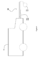
Figure 4 shows a side elevation of a mine detonating apparatus of the present invention coupled to a vehicle; and -
Figure 5 shows a simplified schematic diagram of the control loop formed by the controller, transducer and actuators. - Referring to
Figures 3 and4 , amine detonating apparatus 100 comprises aframe 120 adapted to be pivotably mounted to avehicle 150 about anaxis 160 and two spaced apartroller assemblies frame 120 about theirrespective axes - The
frame 120 can pivot about theaxis 160 in order to vary an angle α between the longitudinal axis of theframe 120 and thevehicle 150. Theroller assemblies respective axes roller assembly frame 120. Eachroller assembly roller assemblies vehicle 150. - The
mine detonating apparatus 100 also includes actuators in the form of, for example, twoframe cylinders frame 120 and thevehicle 150, which can be configured to be disengaged or "float", such that theframe 120 is free to rotate about itspivot axis 160, lock, such that the angle α remains fixed once the frame has been moved into position, or engage, i.e. oneframe cylinder 190a extends/retracts while theother frame cylinder 190b retracts/extends, such that the angle α increases or decreases, respectively. - The
mine detonating apparatus 100 also includes twocastor cylinders roller assembly frame structure 120, wherein each of thecastor cylinders respective roller assemblies respective axes frame structure 120. - The distance between a centre of
rotation 210 of thevehicle 150 and thepivot axis 160 of theframe 120 is defined as length LV. The length of theframe 120 is defined as length LR. - When the
frame cylinders castor cylinders vehicle 150 and the respective geometric parameters LV, LR, α, βL, βR exists. For example, the actual or true turning radius R of the vehicle in a steady state can be determined approximately by the following equation:
- It should be noted that when the
frame 120 is being steered (i.e. α is varying) βL and βR are affected. This needs to be taken into account when calculating R. For example, if α is increasing, βL and βR will be larger than would be the case in the steady state. - It is not necessarily imperative to know both βL and βR in order to calculate the actual or true turning radius of the
vehicle 150. - Referring now to
Figure 5 , themine detonating apparatus 100 further comprises acontrol system 220 that receives an input signal relating to an actual path of thevehicle 150. During operation, thecontrol system 220 continuously receives the input signal relating to the actual path of the vehicle and continuously determines the current desired position of themine detonating apparatus 100. Thecontrol system 220 compares the desired with the actual position of themine detonating apparatus 100 relative to thevehicle 150 and operates any one of theframe cylinders castor cylinder frame 120 into the desired position. The actual position of themine detonating apparatus 100 relative to thevehicle 150 is determined, for example, from the actual rotation angle α determined byrespective transducer 229, which may be a goniometer or displacement sensor mounted on theaxis 160. The input signal used to determine the actual path of thevehicle 150 may comprise the first and second feedback signals 330, 310, 320 relating to the actual rotation angles α, βL and βR fromrespective transducers - Alternatively, the inputs other than α, βL and βR may be used to determine the actual path of the
vehicle 150 may comprise a third feedback signal (not shown) received from, for example, a Global Positioning System (GPS) sensor (not shown), one or more accelerometers (not shown) and/or an inertial navigation system (not shown). The GPS may be mounted to thevehicle 150 orframe structure 120. The accelerometers and inertial navigation system may be mounted to thevehicle 150 and/orframe 120. - When not steering, the
frame cylinders castor cylinders roller assemblies frame structure 120 relative to the vehicle. - Under normal ground surface condition, i.e. when the roller assemblies have sufficient grip on the ground surface, the actual steer angle α of the
frame 120 may be adjusted by disengaging theframe cylinders castor cylinders frame 120 and one of theroller assemblies respective axes other castor cylinder controller 220. In this particular example, the angle βR or βL is varied such that theframe 120 tracks to the specified angle αs as thevehicle 150 advances, theframe cylinders castor cylinder castor cylinder hand roller assembly 130 should be engaged and if it is desired to increase α, the righthand roller assembly 140 should be used to perform the steering operation. The opposite is the case when α is negative. - Under extreme ground surface conditions, where, for example, the roller assemblies have insufficient grip on the ground surface, the actual steer angle α of the
frame 120 may be adjusted by disengaging thecastor cylinders roller assemblies respective axes frame cylinders controller 220 to steer theframe structure 120 until the desired angle αs is achieved. - Preferably, the mine detonating apparatus is steered using one of the
castor cylinders frame cylinders frame cylinder - When reversing the
vehicle 150, thecastor cylinders roller assemblies respective axes frame cylinders axis 160, or locked in a specified position. Alternatively, theframe 120 may be steered into a centre position such that α = 0°. Configuring themine detonating device 100 for reversing can either be carried out manually or automatically by providing a pre-programmed operation sequence to thecontrol system 220, such that thecontrol system 220 executes a specific reversing procedure when 90° < βL < 270° and/or 90° < βR < 270°. - It will be appreciated by persons skilled in the art that the above embodiment has been described by way of example only and not in any limitative sense, and that various alterations and modifications are possible without departing from the scope of the invention as defined by the appended claims.
Claims (15)
- A mine detonating apparatus (100) for a vehicle (150), comprising:- a frame structure (120) pivotably mountable to the vehicle (150);- ground engaging means (130, 140) pivotably mounted to the frame structure (120) for applying a load to the ground;- first actuator means (190a, 190b);- transducer means (229) adapted to provide a first feedback signal (330) related to the position (α) of the frame structure (120) relative to the vehicle (150); and- controller means (220) configured to receive an input signal relating to an actual path of the vehicle (150) and to determine a desired position of the apparatus (100) relative to the vehicle (150); wherein the (220) means is further configured to receive the first feedback signal (330) to determine an actual position of the apparatus (100) relative to the vehicle (150); and operate the first actuator means (190a, 190b) in accordance with a difference between the actual position and the desired position of the apparatus (100) to move the apparatus (100) such that the ground engaging means (130, 140) cover a path subsequently driven over by the vehicle (150); the apparatus (100) being characterized by the first actuator means (190a, 190b) being adapted to move the frame structure (120) relative to the vehicle (150) about a first axis (160) substantially vertical relative to the ground.
- A mine detonating apparatus (100) according to claim 1, further comprising a second actuator means (200a, 200b) adapted to move the ground engaging means (130, 140) relative to the frame structure (120) about a second axis (170, 180) substantially vertical relative to the ground, wherein the controller means (220) is further configured to selectively operate the first actuator means (190a, 190b) and/or the second actuator means (200a, 200b).
- A mine detonating apparatus (100) according to any preceding claim, wherein the transducer means (229) is further adapted to provide a second feedback signal (310, 320) related to the position (βL, βR) of the ground engaging means (130, 140) relative to the frame structure (120).
- A mine detonating apparatus (100) according to claim 3, wherein the input signal comprises the first feedback signal (330) and the second feedback signal (310, 320).
- A mine detonating apparatus (100) according to any preceding claim, further comprising any one or more of a GPS sensor operatively coupled to the mine detonating apparatus (100) and/or configured to be coupled to the vehicle (150); one or more of an accelerometer operatively coupled to the mine detonating apparatus (100) and/or configured to be coupled to the vehicle (150), and an inertial navigation system operatively coupled to the mine detonating apparatus (100) and/or configured to be coupled to vehicle (150).
- A mine detonating apparatus (100) according to claims 4 and 5, wherein the input signal comprises the first and second feedback signals (330, 310, 320) and/or a third feedback signal received from any one or more of the GPS sensor and/or one or more of the accelerometer and/or the inertial navigation system.
- A mine detonating apparatus (100) according to any preceding claim, wherein the ground engaging means (130, 140) comprises one or more ground engaging members.
- A mine detonating apparatus (100) according to claim 7, wherein the ground engaging means (130, 140) comprises two spaced apart ground engaging roller assemblies.
- A mine detonating apparatus (100) according to any preceding claim, wherein the first and/or second actuator means (190a, 190b, 200a, 200b) comprise one or more hydraulically and/or electrically driven actuators.
- A mine detonating apparatus (100) according to claim 8 and 9, wherein the second actuator means (200a, 200b) comprises two second actuators each of which are operatively coupled to a ground engaging roller assembly.
- A mine detonating apparatus (100) according to any preceding claim, wherein the controller means (220) is adapted to selectively lock at least one of the first and second actuator means (190a, 190b, 200a, 200b) to lock the frame structure (120) and/or ground engaging means (130, 140) in a predetermined position.
- A mine detonating apparatus (100) according to any preceding claim, wherein the controller means (220) is adapted to selectively disengage at least one of the first actuator means (190a, 190b) and second actuator means (200a, 200b) to allow the frame structure (120) and/or ground engaging means (130, 140) to move freely about its respective first (160) and/or second (170, 180) axis.
- A mine detonating apparatus (100) according to any preceding claim, wherein the controller means (220) is adapted to receive, store and process computer readable instructions for operating the first (190a, 190b) and/or second (200a, 200b) actuator means.
- A mine detonating apparatus (100) according to any preceding claim, wherein the transducer means (229) comprises at least one goniometric sensor or at least one displacement sensor.
- A mine detonating apparatus (100) according to any preceding claim, wherein the frame structure (120) is adapted to be mounted to the front of the vehicle (150) with respect to the moving direction of the vehicle (150).
Applications Claiming Priority (2)
| Application Number | Priority Date | Filing Date | Title |
|---|---|---|---|
| GBGB1021243.9A GB201021243D0 (en) | 2010-12-15 | 2010-12-15 | A mine detonating apparatus and a method of steering the same |
| PCT/GB2011/052461 WO2012080719A1 (en) | 2010-12-15 | 2011-12-13 | A mine detonating apparatus and a method of steering the same |
Publications (2)
| Publication Number | Publication Date |
|---|---|
| EP2652435A1 EP2652435A1 (en) | 2013-10-23 |
| EP2652435B1 true EP2652435B1 (en) | 2015-04-08 |
Family
ID=43567214
Family Applications (1)
| Application Number | Title | Priority Date | Filing Date |
|---|---|---|---|
| EP11808287.4A Active EP2652435B1 (en) | 2010-12-15 | 2011-12-13 | A mine detonating apparatus and a method of steering the same |
Country Status (3)
| Country | Link |
|---|---|
| EP (1) | EP2652435B1 (en) |
| GB (1) | GB201021243D0 (en) |
| WO (1) | WO2012080719A1 (en) |
Families Citing this family (2)
| Publication number | Priority date | Publication date | Assignee | Title |
|---|---|---|---|---|
| CN111964533B (en) * | 2020-08-31 | 2022-08-26 | 重庆元韩汽车技术设计研究院有限公司 | Mine sweeping roller |
| FR3123425B1 (en) | 2021-05-25 | 2024-08-23 | Sera Ingenierie | MASSIVE TRAJECTORY CONTROLLED DECOY SYSTEM |
Family Cites Families (3)
| Publication number | Priority date | Publication date | Assignee | Title |
|---|---|---|---|---|
| DE2632568A1 (en) * | 1976-07-20 | 1978-01-26 | Kaelble Gmbh C | Ground mines clearing machine - has articulated arms connected to tank with rollers covering several vehicle widths |
| GB0016402D0 (en) | 2000-07-03 | 2000-08-23 | Pearson Engineering Limited | Mine detonating apparatus and vehicle including such apparatus |
| GB0810643D0 (en) | 2008-06-11 | 2008-07-16 | Firth Charles B | Mine detonating apparatus |
-
2010
- 2010-12-15 GB GBGB1021243.9A patent/GB201021243D0/en not_active Ceased
-
2011
- 2011-12-13 EP EP11808287.4A patent/EP2652435B1/en active Active
- 2011-12-13 WO PCT/GB2011/052461 patent/WO2012080719A1/en not_active Ceased
Also Published As
| Publication number | Publication date |
|---|---|
| EP2652435A1 (en) | 2013-10-23 |
| GB201021243D0 (en) | 2011-01-26 |
| WO2012080719A1 (en) | 2012-06-21 |
Similar Documents
| Publication | Publication Date | Title |
|---|---|---|
| EP2780770B1 (en) | Method and system for driving a mining and/or construction machine in a safe manner without the risk of collision | |
| US9037346B2 (en) | Steering control for vehicle trains | |
| AU2013212511B2 (en) | Steering system and method for train vehicle | |
| EP2133652B1 (en) | Mine detonating apparatus | |
| ES2403288T3 (en) | Airplane tug without towbar | |
| EP1886901B1 (en) | Steering control apparatus, steering control system, and steering control program | |
| US7835836B2 (en) | Methods, systems, and computer program products for calculating a torque overlay command in a steering control system | |
| CN111108035A (en) | Method and system for controlling vehicle lane keeping | |
| EP4033323A1 (en) | Conveying vehicle | |
| US10160486B2 (en) | Steering system and method for controlling steering system | |
| WO2014011821A1 (en) | Steering and control systems for a three-wheeled vehicle | |
| US7350613B2 (en) | Transport with rotatable load and safety bumper | |
| US9062940B2 (en) | Mine detonating apparatus | |
| EP2695811B1 (en) | Landing gear assembly of aircraft | |
| CN106515900A (en) | AGV mobile device | |
| EP2604495A1 (en) | Method and device for controlling the motion of an articulated vehicle | |
| WO2002003007A1 (en) | Mine detonating apparatus and vehicle including such apparatus | |
| US11180146B2 (en) | Brake control technique to stop a vehicle for assisting automatic trailer hitching | |
| US20060056949A1 (en) | Transport vehicle for aircraft | |
| EP2938531B1 (en) | A control method of a power steering system for a vehicle having two steered axles | |
| EP2652435A1 (en) | A mine detonating apparatus and a method of steering the same | |
| Inotsume et al. | Analysis of grouser performance to develop guidelines for design for planetary rovers | |
| EP2247463B1 (en) | Method for determining a wheel reference speed of a wheel on a vehicle having hydrostatic drive, and device for determining a wheel reference speed of a wheel of a vehicle having hydrostatic drive | |
| US9056624B2 (en) | Front wheel drive control | |
| WO2004028903A1 (en) | Tractor, particularly for towing aircraft |
Legal Events
| Date | Code | Title | Description |
|---|---|---|---|
| PUAI | Public reference made under article 153(3) epc to a published international application that has entered the european phase |
Free format text: ORIGINAL CODE: 0009012 |
|
| 17P | Request for examination filed |
Effective date: 20130410 |
|
| AK | Designated contracting states |
Kind code of ref document: A1 Designated state(s): AL AT BE BG CH CY CZ DE DK EE ES FI FR GB GR HR HU IE IS IT LI LT LU LV MC MK MT NL NO PL PT RO RS SE SI SK SM TR |
|
| DAX | Request for extension of the european patent (deleted) | ||
| GRAP | Despatch of communication of intention to grant a patent |
Free format text: ORIGINAL CODE: EPIDOSNIGR1 |
|
| INTG | Intention to grant announced |
Effective date: 20141113 |
|
| GRAJ | Information related to disapproval of communication of intention to grant by the applicant or resumption of examination proceedings by the epo deleted |
Free format text: ORIGINAL CODE: EPIDOSDIGR1 |
|
| GRAP | Despatch of communication of intention to grant a patent |
Free format text: ORIGINAL CODE: EPIDOSNIGR1 |
|
| INTG | Intention to grant announced |
Effective date: 20150122 |
|
| GRAS | Grant fee paid |
Free format text: ORIGINAL CODE: EPIDOSNIGR3 |
|
| GRAA | (expected) grant |
Free format text: ORIGINAL CODE: 0009210 |
|
| AK | Designated contracting states |
Kind code of ref document: B1 Designated state(s): AL AT BE BG CH CY CZ DE DK EE ES FI FR GB GR HR HU IE IS IT LI LT LU LV MC MK MT NL NO PL PT RO RS SE SI SK SM TR |
|
| REG | Reference to a national code |
Ref country code: GB Ref legal event code: FG4D |
|
| REG | Reference to a national code |
Ref country code: CH Ref legal event code: EP |
|
| REG | Reference to a national code |
Ref country code: IE Ref legal event code: FG4D |
|
| REG | Reference to a national code |
Ref country code: DE Ref legal event code: R096 Ref document number: 602011015566 Country of ref document: DE Effective date: 20150513 |
|
| REG | Reference to a national code |
Ref country code: AT Ref legal event code: REF Ref document number: 720922 Country of ref document: AT Kind code of ref document: T Effective date: 20150515 |
|
| REG | Reference to a national code |
Ref country code: AT Ref legal event code: MK05 Ref document number: 720922 Country of ref document: AT Kind code of ref document: T Effective date: 20150408 |
|
| REG | Reference to a national code |
Ref country code: NL Ref legal event code: VDEP Effective date: 20150408 |
|
| REG | Reference to a national code |
Ref country code: LT Ref legal event code: MG4D |
|
| PG25 | Lapsed in a contracting state [announced via postgrant information from national office to epo] |
Ref country code: NL Free format text: LAPSE BECAUSE OF FAILURE TO SUBMIT A TRANSLATION OF THE DESCRIPTION OR TO PAY THE FEE WITHIN THE PRESCRIBED TIME-LIMIT Effective date: 20150408 |
|
| PG25 | Lapsed in a contracting state [announced via postgrant information from national office to epo] |
Ref country code: HR Free format text: LAPSE BECAUSE OF FAILURE TO SUBMIT A TRANSLATION OF THE DESCRIPTION OR TO PAY THE FEE WITHIN THE PRESCRIBED TIME-LIMIT Effective date: 20150408 Ref country code: ES Free format text: LAPSE BECAUSE OF FAILURE TO SUBMIT A TRANSLATION OF THE DESCRIPTION OR TO PAY THE FEE WITHIN THE PRESCRIBED TIME-LIMIT Effective date: 20150408 Ref country code: NO Free format text: LAPSE BECAUSE OF FAILURE TO SUBMIT A TRANSLATION OF THE DESCRIPTION OR TO PAY THE FEE WITHIN THE PRESCRIBED TIME-LIMIT Effective date: 20150708 Ref country code: LT Free format text: LAPSE BECAUSE OF FAILURE TO SUBMIT A TRANSLATION OF THE DESCRIPTION OR TO PAY THE FEE WITHIN THE PRESCRIBED TIME-LIMIT Effective date: 20150408 Ref country code: PT Free format text: LAPSE BECAUSE OF FAILURE TO SUBMIT A TRANSLATION OF THE DESCRIPTION OR TO PAY THE FEE WITHIN THE PRESCRIBED TIME-LIMIT Effective date: 20150810 Ref country code: FI Free format text: LAPSE BECAUSE OF FAILURE TO SUBMIT A TRANSLATION OF THE DESCRIPTION OR TO PAY THE FEE WITHIN THE PRESCRIBED TIME-LIMIT Effective date: 20150408 |
|
| PG25 | Lapsed in a contracting state [announced via postgrant information from national office to epo] |
Ref country code: GR Free format text: LAPSE BECAUSE OF FAILURE TO SUBMIT A TRANSLATION OF THE DESCRIPTION OR TO PAY THE FEE WITHIN THE PRESCRIBED TIME-LIMIT Effective date: 20150709 Ref country code: IS Free format text: LAPSE BECAUSE OF FAILURE TO SUBMIT A TRANSLATION OF THE DESCRIPTION OR TO PAY THE FEE WITHIN THE PRESCRIBED TIME-LIMIT Effective date: 20150808 Ref country code: RS Free format text: LAPSE BECAUSE OF FAILURE TO SUBMIT A TRANSLATION OF THE DESCRIPTION OR TO PAY THE FEE WITHIN THE PRESCRIBED TIME-LIMIT Effective date: 20150408 Ref country code: LV Free format text: LAPSE BECAUSE OF FAILURE TO SUBMIT A TRANSLATION OF THE DESCRIPTION OR TO PAY THE FEE WITHIN THE PRESCRIBED TIME-LIMIT Effective date: 20150408 Ref country code: AT Free format text: LAPSE BECAUSE OF FAILURE TO SUBMIT A TRANSLATION OF THE DESCRIPTION OR TO PAY THE FEE WITHIN THE PRESCRIBED TIME-LIMIT Effective date: 20150408 |
|
| REG | Reference to a national code |
Ref country code: DE Ref legal event code: R097 Ref document number: 602011015566 Country of ref document: DE |
|
| PG25 | Lapsed in a contracting state [announced via postgrant information from national office to epo] |
Ref country code: DK Free format text: LAPSE BECAUSE OF FAILURE TO SUBMIT A TRANSLATION OF THE DESCRIPTION OR TO PAY THE FEE WITHIN THE PRESCRIBED TIME-LIMIT Effective date: 20150408 Ref country code: EE Free format text: LAPSE BECAUSE OF FAILURE TO SUBMIT A TRANSLATION OF THE DESCRIPTION OR TO PAY THE FEE WITHIN THE PRESCRIBED TIME-LIMIT Effective date: 20150408 |
|
| PLBE | No opposition filed within time limit |
Free format text: ORIGINAL CODE: 0009261 |
|
| STAA | Information on the status of an ep patent application or granted ep patent |
Free format text: STATUS: NO OPPOSITION FILED WITHIN TIME LIMIT |
|
| PG25 | Lapsed in a contracting state [announced via postgrant information from national office to epo] |
Ref country code: SK Free format text: LAPSE BECAUSE OF FAILURE TO SUBMIT A TRANSLATION OF THE DESCRIPTION OR TO PAY THE FEE WITHIN THE PRESCRIBED TIME-LIMIT Effective date: 20150408 Ref country code: PL Free format text: LAPSE BECAUSE OF FAILURE TO SUBMIT A TRANSLATION OF THE DESCRIPTION OR TO PAY THE FEE WITHIN THE PRESCRIBED TIME-LIMIT Effective date: 20150408 Ref country code: RO Free format text: LAPSE BECAUSE OF NON-PAYMENT OF DUE FEES Effective date: 20150408 Ref country code: CZ Free format text: LAPSE BECAUSE OF FAILURE TO SUBMIT A TRANSLATION OF THE DESCRIPTION OR TO PAY THE FEE WITHIN THE PRESCRIBED TIME-LIMIT Effective date: 20150408 |
|
| 26N | No opposition filed |
Effective date: 20160111 |
|
| PG25 | Lapsed in a contracting state [announced via postgrant information from national office to epo] |
Ref country code: IT Free format text: LAPSE BECAUSE OF FAILURE TO SUBMIT A TRANSLATION OF THE DESCRIPTION OR TO PAY THE FEE WITHIN THE PRESCRIBED TIME-LIMIT Effective date: 20150408 |
|
| PG25 | Lapsed in a contracting state [announced via postgrant information from national office to epo] |
Ref country code: SI Free format text: LAPSE BECAUSE OF FAILURE TO SUBMIT A TRANSLATION OF THE DESCRIPTION OR TO PAY THE FEE WITHIN THE PRESCRIBED TIME-LIMIT Effective date: 20150408 Ref country code: BE Free format text: LAPSE BECAUSE OF NON-PAYMENT OF DUE FEES Effective date: 20151231 |
|
| REG | Reference to a national code |
Ref country code: DE Ref legal event code: R119 Ref document number: 602011015566 Country of ref document: DE |
|
| PG25 | Lapsed in a contracting state [announced via postgrant information from national office to epo] |
Ref country code: LU Free format text: LAPSE BECAUSE OF FAILURE TO SUBMIT A TRANSLATION OF THE DESCRIPTION OR TO PAY THE FEE WITHIN THE PRESCRIBED TIME-LIMIT Effective date: 20151213 Ref country code: MC Free format text: LAPSE BECAUSE OF FAILURE TO SUBMIT A TRANSLATION OF THE DESCRIPTION OR TO PAY THE FEE WITHIN THE PRESCRIBED TIME-LIMIT Effective date: 20150408 |
|
| REG | Reference to a national code |
Ref country code: CH Ref legal event code: PL |
|
| PG25 | Lapsed in a contracting state [announced via postgrant information from national office to epo] |
Ref country code: BE Free format text: LAPSE BECAUSE OF FAILURE TO SUBMIT A TRANSLATION OF THE DESCRIPTION OR TO PAY THE FEE WITHIN THE PRESCRIBED TIME-LIMIT Effective date: 20150408 |
|
| REG | Reference to a national code |
Ref country code: IE Ref legal event code: MM4A |
|
| REG | Reference to a national code |
Ref country code: FR Ref legal event code: ST Effective date: 20160831 |
|
| PG25 | Lapsed in a contracting state [announced via postgrant information from national office to epo] |
Ref country code: LI Free format text: LAPSE BECAUSE OF NON-PAYMENT OF DUE FEES Effective date: 20151231 Ref country code: IE Free format text: LAPSE BECAUSE OF NON-PAYMENT OF DUE FEES Effective date: 20151213 Ref country code: DE Free format text: LAPSE BECAUSE OF NON-PAYMENT OF DUE FEES Effective date: 20160701 Ref country code: CH Free format text: LAPSE BECAUSE OF NON-PAYMENT OF DUE FEES Effective date: 20151231 |
|
| PG25 | Lapsed in a contracting state [announced via postgrant information from national office to epo] |
Ref country code: FR Free format text: LAPSE BECAUSE OF NON-PAYMENT OF DUE FEES Effective date: 20151231 |
|
| PG25 | Lapsed in a contracting state [announced via postgrant information from national office to epo] |
Ref country code: SM Free format text: LAPSE BECAUSE OF FAILURE TO SUBMIT A TRANSLATION OF THE DESCRIPTION OR TO PAY THE FEE WITHIN THE PRESCRIBED TIME-LIMIT Effective date: 20150408 Ref country code: BG Free format text: LAPSE BECAUSE OF FAILURE TO SUBMIT A TRANSLATION OF THE DESCRIPTION OR TO PAY THE FEE WITHIN THE PRESCRIBED TIME-LIMIT Effective date: 20150408 Ref country code: HU Free format text: LAPSE BECAUSE OF FAILURE TO SUBMIT A TRANSLATION OF THE DESCRIPTION OR TO PAY THE FEE WITHIN THE PRESCRIBED TIME-LIMIT; INVALID AB INITIO Effective date: 20111213 |
|
| PG25 | Lapsed in a contracting state [announced via postgrant information from national office to epo] |
Ref country code: SE Free format text: LAPSE BECAUSE OF FAILURE TO SUBMIT A TRANSLATION OF THE DESCRIPTION OR TO PAY THE FEE WITHIN THE PRESCRIBED TIME-LIMIT Effective date: 20150408 Ref country code: CY Free format text: LAPSE BECAUSE OF FAILURE TO SUBMIT A TRANSLATION OF THE DESCRIPTION OR TO PAY THE FEE WITHIN THE PRESCRIBED TIME-LIMIT Effective date: 20150408 |
|
| PG25 | Lapsed in a contracting state [announced via postgrant information from national office to epo] |
Ref country code: MT Free format text: LAPSE BECAUSE OF FAILURE TO SUBMIT A TRANSLATION OF THE DESCRIPTION OR TO PAY THE FEE WITHIN THE PRESCRIBED TIME-LIMIT Effective date: 20150408 |
|
| PG25 | Lapsed in a contracting state [announced via postgrant information from national office to epo] |
Ref country code: TR Free format text: LAPSE BECAUSE OF FAILURE TO SUBMIT A TRANSLATION OF THE DESCRIPTION OR TO PAY THE FEE WITHIN THE PRESCRIBED TIME-LIMIT Effective date: 20150408 Ref country code: MK Free format text: LAPSE BECAUSE OF FAILURE TO SUBMIT A TRANSLATION OF THE DESCRIPTION OR TO PAY THE FEE WITHIN THE PRESCRIBED TIME-LIMIT Effective date: 20150408 |
|
| PG25 | Lapsed in a contracting state [announced via postgrant information from national office to epo] |
Ref country code: AL Free format text: LAPSE BECAUSE OF FAILURE TO SUBMIT A TRANSLATION OF THE DESCRIPTION OR TO PAY THE FEE WITHIN THE PRESCRIBED TIME-LIMIT Effective date: 20150408 |
|
| PGFP | Annual fee paid to national office [announced via postgrant information from national office to epo] |
Ref country code: GB Payment date: 20251224 Year of fee payment: 15 |