EP2652420B1 - Evaporator - Google Patents
Evaporator Download PDFInfo
- Publication number
- EP2652420B1 EP2652420B1 EP11808455.7A EP11808455A EP2652420B1 EP 2652420 B1 EP2652420 B1 EP 2652420B1 EP 11808455 A EP11808455 A EP 11808455A EP 2652420 B1 EP2652420 B1 EP 2652420B1
- Authority
- EP
- European Patent Office
- Prior art keywords
- evaporator
- housing
- fan
- fan module
- replaceable
- Prior art date
- Legal status (The legal status is an assumption and is not a legal conclusion. Google has not performed a legal analysis and makes no representation as to the accuracy of the status listed.)
- Active
Links
Images





Classifications
-
- F—MECHANICAL ENGINEERING; LIGHTING; HEATING; WEAPONS; BLASTING
- F25—REFRIGERATION OR COOLING; COMBINED HEATING AND REFRIGERATION SYSTEMS; HEAT PUMP SYSTEMS; MANUFACTURE OR STORAGE OF ICE; LIQUEFACTION SOLIDIFICATION OF GASES
- F25D—REFRIGERATORS; COLD ROOMS; ICE-BOXES; COOLING OR FREEZING APPARATUS NOT OTHERWISE PROVIDED FOR
- F25D17/00—Arrangements for circulating cooling fluids; Arrangements for circulating gas, e.g. air, within refrigerated spaces
- F25D17/04—Arrangements for circulating cooling fluids; Arrangements for circulating gas, e.g. air, within refrigerated spaces for circulating air, e.g. by convection
- F25D17/06—Arrangements for circulating cooling fluids; Arrangements for circulating gas, e.g. air, within refrigerated spaces for circulating air, e.g. by convection by forced circulation
- F25D17/067—Evaporator fan units
-
- F—MECHANICAL ENGINEERING; LIGHTING; HEATING; WEAPONS; BLASTING
- F25—REFRIGERATION OR COOLING; COMBINED HEATING AND REFRIGERATION SYSTEMS; HEAT PUMP SYSTEMS; MANUFACTURE OR STORAGE OF ICE; LIQUEFACTION SOLIDIFICATION OF GASES
- F25D—REFRIGERATORS; COLD ROOMS; ICE-BOXES; COOLING OR FREEZING APPARATUS NOT OTHERWISE PROVIDED FOR
- F25D2317/00—Details or arrangements for circulating cooling fluids; Details or arrangements for circulating gas, e.g. air, within refrigerated spaces, not provided for in other groups of this subclass
- F25D2317/06—Details or arrangements for circulating cooling fluids; Details or arrangements for circulating gas, e.g. air, within refrigerated spaces, not provided for in other groups of this subclass with forced air circulation
- F25D2317/068—Details or arrangements for circulating cooling fluids; Details or arrangements for circulating gas, e.g. air, within refrigerated spaces, not provided for in other groups of this subclass with forced air circulation characterised by the fans
-
- F—MECHANICAL ENGINEERING; LIGHTING; HEATING; WEAPONS; BLASTING
- F28—HEAT EXCHANGE IN GENERAL
- F28D—HEAT-EXCHANGE APPARATUS, NOT PROVIDED FOR IN ANOTHER SUBCLASS, IN WHICH THE HEAT-EXCHANGE MEDIA DO NOT COME INTO DIRECT CONTACT
- F28D1/00—Heat-exchange apparatus having stationary conduit assemblies for one heat-exchange medium only, the media being in contact with different sides of the conduit wall, in which the other heat-exchange medium is a large body of fluid, e.g. domestic or motor car radiators
- F28D1/02—Heat-exchange apparatus having stationary conduit assemblies for one heat-exchange medium only, the media being in contact with different sides of the conduit wall, in which the other heat-exchange medium is a large body of fluid, e.g. domestic or motor car radiators with heat-exchange conduits immersed in the body of fluid
- F28D1/04—Heat-exchange apparatus having stationary conduit assemblies for one heat-exchange medium only, the media being in contact with different sides of the conduit wall, in which the other heat-exchange medium is a large body of fluid, e.g. domestic or motor car radiators with heat-exchange conduits immersed in the body of fluid with tubular conduits
- F28D1/047—Heat-exchange apparatus having stationary conduit assemblies for one heat-exchange medium only, the media being in contact with different sides of the conduit wall, in which the other heat-exchange medium is a large body of fluid, e.g. domestic or motor car radiators with heat-exchange conduits immersed in the body of fluid with tubular conduits the conduits being bent, e.g. in a serpentine or zig-zag
- F28D1/0477—Heat-exchange apparatus having stationary conduit assemblies for one heat-exchange medium only, the media being in contact with different sides of the conduit wall, in which the other heat-exchange medium is a large body of fluid, e.g. domestic or motor car radiators with heat-exchange conduits immersed in the body of fluid with tubular conduits the conduits being bent, e.g. in a serpentine or zig-zag the conduits being bent in a serpentine or zig-zag
-
- F—MECHANICAL ENGINEERING; LIGHTING; HEATING; WEAPONS; BLASTING
- F28—HEAT EXCHANGE IN GENERAL
- F28F—DETAILS OF HEAT-EXCHANGE AND HEAT-TRANSFER APPARATUS, OF GENERAL APPLICATION
- F28F1/00—Tubular elements; Assemblies of tubular elements
- F28F1/10—Tubular elements and assemblies thereof with means for increasing heat-transfer area, e.g. with fins, with projections, with recesses
- F28F1/12—Tubular elements and assemblies thereof with means for increasing heat-transfer area, e.g. with fins, with projections, with recesses the means being only outside the tubular element
- F28F1/24—Tubular elements and assemblies thereof with means for increasing heat-transfer area, e.g. with fins, with projections, with recesses the means being only outside the tubular element and extending transversely
- F28F1/32—Tubular elements and assemblies thereof with means for increasing heat-transfer area, e.g. with fins, with projections, with recesses the means being only outside the tubular element and extending transversely the means having portions engaging further tubular elements
Definitions
- the present application relates generally to refrigeration systems and more particularly relates to a modular evaporator and components thereof for use within a walk-in cooler and other types of refrigeration systems.
- Modem air conditioning and refrigeration systems provide cooling, ventilation, and humidity control for all or part of an enclosure such as a building, a cooler, and the like.
- the refrigeration cycle includes four basic stages to provide cooling. First, a vapor refrigerant is compressed within a compressor at high pressure and heated to a high temperature. Second, the compressed vapor is cooled within a condenser by heat exchange with ambient air drawn or blown across a condenser coil by a fan and the like. Third, the liquid refrigerant is passed through an expansion device that reduces both the pressure and the temperature of the liquid refrigerant. The liquid refrigerant is then pumped within the enclosure to an evaporator.
- the liquid refrigerant absorbs heat by blowing or drawing air across the evaporator coil as the liquid refrigerant changes to vapor. Finally, the vapor is returned to the compressor and the cycle repeats.
- This basic refrigeration cycle are known and also may be used herein.
- Conventional walk-in coolers such as those typically found in the food service industry and the like, generally have an evaporator therein similar to that described above.
- the evaporator typically is hung from the ceiling of the cooler.
- the evaporator thus may take up space within the cooler that could have been used for storage or other purposes.
- the evaporator also may present a hazard in that the evaporator may extend downward into the usual standing area so as to present a risk of injury for individuals walking therein.
- a condensate drain may hang below the evaporator.
- the condensate drain also may take up useful storage space and itself may be an injury risk.
- Typical evaporators generally also require extensive disassembly so as to repair and/or replace a component therein such as a fan and the like.
- Such disassembly procedures generally involves shutting down the cooler and may involve transferring all of the items stored therein.
- repairs that do not involve shutting down the cooler at least require the workman to work in the refrigerated space for an extended period of time. Repairing an existing evaporator thus may be a somewhat costly and time intensive procedure.
- installing a new evaporator may be difficult given the typical weight involved and the difficulty in maneuvering in the close spaces typically found therein.
- Such an improved evaporator design preferably may take up less storage space therein and create less of an injury hazard while providing easy access thereto for repair and/or replacement of the components therein.
- EP 0697574 discloses the features of the pre-characterizing portion of claim 1.
- the present invention provides an evaporator according to claim 1 for use within a walk-in cooler, comprising: a housing; the housing mountable within the cooler; a coil assembly mounted within the housing; and a replaceable fan module positionable within the housing when the housing is mounted within the cooler; wherein the replaceable fan module comprises a locking member thereon so as to lock the replaceable fan module within the housing, and characterized in that: the replaceable fan module comprises a backward incline centrifugal fan mounted therein; and the replaceable fan module comprises a replaceable venturi ring sized to accommodate the fan.
- the invention provides a method of installing an evaporator according to claim 1 within a cooler, comprising: attaching an evaporator housing with a coil assembly mounted therein to the cooler; positioning a replaceable fan module into the evaporator housing while the evaporator housing is attached to the cooler; and locking the fan module in place.
- Figs. 1-4 show an evaporator 100 as may be described herein.
- the evaporator 100 may be positioned within a cooler 110.
- the evaporator 100 typically is positioned on a ceiling 115 thereof.
- the cooler 110 may be any type of chilled enclosure and may include refrigerators, freezers, or any structure chilled below typical ambient temperatures.
- the cooler 110 may have any desired size, shape, or configuration.
- the evaporator 100 described herein is in no way limited by the type or design of the cooler 110.
- a drain line 120 may extend from the evaporator 100 to the exterior of the cooler 110.
- the drain line 120 may have any desired size, shape, or configuration.
- the evaporator 100 may be in communication with other types of refrigeration equipment such as the components of the refrigeration cycle described above and the like.
- the overall evaporator 100 may be modular in nature as will be described in more detail below such that the components thereof may be easily installed and replaced.
- the evaporator 100 includes a housing 130.
- the housing 130 maybe made in whole or in part out of molded plastics. Metals and other types of substantially rigid materials also may be used as the panel and/or as a backbone-type structure.
- the housing 130 may include a top panel 140, a drain pan 150, and a pair of side panels 160.
- the top panel 140 may include a number of mounting brackets 170 attached thereto.
- the mounting brackets 170 may extend from one end of the top panel 140.
- the top panel 140 also may have a number of mounting apertures 180 positioned therein.
- the mounting brackets 170 and the mounting apertures 180 may have any size, shape, or configuration.
- the top panel 140 may be attached to the ceiling 115 of the cooler 110 or other structure via the mounting brackets 170 and the mounting apertures 180 as well as conventional types of fasteners such as bolts and the like.
- the drain pan 150 may have one or more drain channels 190 formed therein.
- the drain channels 190 may lead to a drain pipe 200 on one end thereof.
- the drain pipe 200 may extend outwardly and slightly downwardly from the drain pan 150.
- the drain pipe 200 may be in communication with the drain line 120.
- the drain pan 150 also may have a degree of slope itself leading to the drain pipe 200.
- the drain pan 150 also may include a raised lip 210 positioned about a periphery thereof. The raised lip 210 permits the drain pan 150 to catch water droplets on the exterior thereof.
- a submersible pump also may be used herein. Other configurations and other components may be used.
- the side panels 160 may include a service access panel 220 and a non-service access panel 230.
- the service access panel 220 provides access to the refrigeration components as will be described in more detail below as well as an electrical module 240.
- the electrical module 240 includes all of the electrical components and controls for the operation of the overall evaporator 100.
- the electrical module 240 and the other electrical components of the overall evaporator 100 may be prewired for easy installation.
- a high voltage barrier panel 250 may surround the electrical module 240.
- a wiring diagram or other types of information may be positioned about the service access panel 220.
- the service access panel 220 and the non-service access panel 230 may be hinged for access thereto. Other configurations and other components may be used herein.
- a coil assembly 260 may be mounted onto the top panel 140 or otherwise.
- the coil assembly 260 may includes a number of tubes with a number of spaced fins 280.
- the tubes 270 may extend through a pair of end plates 290.
- the tubes 270 and the fins 280 may be made out of copper, aluminum, or other types of substantially rigid materials with good heat transfer characteristics.
- the fins 280 may be corrugated. Other configurations and other components may be used herein.
- the coil assembly 260 may have a more open tube design than is typically found in conventional refrigeration units.
- the tubes 270 may have an outside diameter of about seven (7) millimeters with a tube spacing 300 of about twenty-seven (27) millimeters or more and a row spacing 310 of about twenty-three (23) millimeters or more in an off-set fashion.
- the use of the expanded tube spacing 300, 310 thus provides less of a pressure drop therethrough and may reduce the refrigerant charge needed therein.
- tubes 270 with smaller diameters are positioned closer together. This "closeness", however, tends to aid in the development of frost due to the reduced span therebetween.
- the tube pattern described herein has smaller tube diameters but maintains the larger spacing such that the building of frost is not increased.
- the dimensions described herein are for purposes of example only. Other dimensions may be used herein.
- the coil assembly 260 may be in communication with a refrigeration tubing/piping 320.
- the refrigeration tubing/piping 320 may have any desired size, shape or configuration.
- the refrigeration tubing/piping 320 may be in communication with other types of refrigeration components such as those described above and the like. Other components and other configurations may be used herein.
- the evaporator 100 also includes a fan module comprising a replaceable venturi ring.
- Fig. 6 shows a fan module 330 including a fan housing 340 without such a venturi ring, which will be described below with reference to Figs. 7 and 8 .
- the fan housing 340 may be made out of molded plastics, metals, and other types of substantially rigid materials.
- the fan housing 340 has a number of mounting rails 350 positioned thereon.
- the mounting rails 350 may mate with a number of top panel rails 360 positioned about the top panel 140.
- the use of the mounting rails 350 and the top panel rails 360 allows the fan module 330 as a whole to slide in and out of the housing 130 of the evaporator 100 as a whole.
- a fan wiring harness 365 and the like may extend along the top panel rails 360 and/or otherwise within the housing 130 and may be in communication with the fan module 330 and the electrical module 240 and/or other controls as the fan module 330 slides therein.
- the fan housing 340 also includes a locking member 370 positioned thereon.
- the locking member 370 may be biased into the locked positioned.
- the locking member 370 may mate with a receiving member 380 positioned about the top panel 140 or otherwise (including the reverse).
- the locking member 370 and the receiving member 380 may cooperate to lock the fan module 330 into place.
- Other types of locking mechanism may be used herein.
- the fan module 330 includes a fan 390 mounted within the fan housing 340.
- the fan 390 is a backward incline centrifugal fan.
- the backward incline centrifugal fan may have an overall reduced height as compared to conventional axial refrigeration fans.
- a backward incline centrifugal fan generally is used in air handlers as opposed to refrigeration units due to the ability of the fan to overcome high static pressure loads associated with duct work.
- the fan 390 may be a variable speed fan. The fan 390 pulls the airflow through the coil assembly 260 and turns the flow into the cooler 110 or other refrigerated space.
- the fan module 330 also may include a fan motor 400, one or more air plenums 410, and electronic and other controls.
- the electronics and the other components may be placed in communication with the electrical module 240 via the wiring harness 365 via one or more quick disconnect fittings or otherwise.
- Other types of fans 390, fan motors 400, and controls may be used herein.
- Other components and other configurations may be used herein.
- the fan module 330 also includes a grill 420 so as to enclose one end of the housing 340.
- the grill 420 may be made out of molded plastics, metals, and other types of substantially rigid materials.
- the grill 420 may have any size, shape, or configuration.
- the grill 420 may be attached by a number of clips or other attachment means for easy access thereto and for easy cleaning.
- the evaporator 100 may be attached to the ceiling 115 of the cooler 110 or other type of structure.
- a template may be used to align the location of the mounting brackets 170 and the mounting apertures 180 so as to drill the appropriate holes and the like.
- the fan module 330 need not be positioned within the housing 130. Removing the fan module 330 makes the overall evaporator 100 lighter and makes attachment to the cooler 110 considerably easier than may be possible with known units.
- the coil assembly 260 and the electrical module 240 with the related wiring may be premounted to the housing 130. Once the housing 130 is installed, the fan module 330 may be slid within the housing 130 via the mounting rails 350 and the top panel rails 360.
- the electronics and other controls are prewired such that communication with the electrical module 340 is established as the fan module 330 slides therein. Multiple fan modules 330 may be used in a single housing 130.
- Access to the electrical module 340 and the coil assembly 260 may be provided via the service access panel 220.
- the fan module 330 may be quickly and easily removed from the housing 130 for repair, replacement, and/or cleaning. For example, removing the fan module 330 provides access for coil cleaning, drain pan cleaning, and the like.
- the fan module 330 may be slid out to an intermediate position or a retracted position or the locking member 370 may be released such that the fan module 330 may be removed completely.
- the fan module 330 thus may have at least an installed position, a retracted position, and a removed position.
- the fan module 330 may be removed from the housing 130 of the evaporator 100 and repaired outside of the cooler 110.
- the evaporator 100 thus provides ease of installation and ease of access with a relatively low profile.
- the evaporator described herein may be about eleven (11) inches (about 27.94 centimeter) or so. These dimensions are for the purpose of comparison only and any height may be used herein. Nonetheless, the evaporator 100 described herein provides more storage room for the cooler 110 given the reduced profile. Likewise, the risk of injury also may be reduced herein.
- Figs. 7 and 8 show a fan module 500 having a replaceable venturi ring. Similar to the fan module 330 described above, the fan module 500 also may slide into the evaporator 100.
- the fan module 500 thus may include a fan housing 510.
- the fan housing 510 may be made out of molded plastics, metals, and other types of substantially rigid or semi-rigid materials.
- the fan housing 510 may have a number of mounting rails 520 positioned thereon.
- the mounting rails 520 mate with the top panel rails 360 positioned about the top panel 140.
- a fan wiring harness 530 and the like may extend along the fan module 500 and may be in communication with the electrical module 240 and/or other controls.
- the fan module 500 also may include a fan assembly 540.
- the fan assembly 540 may include a fan 550 and a fan motor 560 positioned on a fan mounting bracket 570.
- the fan 550 is a backward incline centrifugal fan.
- the fan 550 may be a variable speed fan.
- the fan housing 510 may have a fan aperture 580 formed therein.
- the fan assembly 540 may be positioned within the fan aperture 580.
- the fan mounting bracket 570 may be attached to the fan housing 510 via screws 590 or other types of conventional fastening means.
- the fan module 500 also may include one or more air plenums 600.
- the air plenums 600 direct the flow of air from the coil assembly 260 through the fan assembly 540 and into the cooler 110 or other refrigerated space.
- Other types of fans 550, fan motors 560, and controls may be used herein.
- Other components and other configurations also may be used herein.
- the fan module 500 also includes a replaceable venturi ring 610.
- the replaceable venturi ring 610 may snap into the fan housing 510 and may be positioned about the fan 550.
- the replaceable venturi ring 610 enhances the efficiency of the fan 550 by forming a venturi thereabout.
- the velocity of the airflow therethrough increases as the cross-sectional area of the flow path decreases through the venturi ring 610. Given such, the respective sizes of the fan 550 and the replaceable venturi ring 610 may be a significant design consideration.
- the replaceable venturi ring 610 may have an attachment disk 620 with a number of attachment hooks 630.
- the attachment hooks 630 may be substantially harpoon like in shape and may snap into a number of fan housing apertures 640 formed in the fan housing 510. Although three (3) attachment hooks 630 are shown, any number of attachment hooks 630 may be used herein.
- the replaceable venturi ring 610 may be made out of substantially rigid or semi-rigid plastics and the like.
- the attachment hooks 630 may have some flexibility in order to be inserted in and removed from the fan housing apertures 640.
- the venturi ring 610 also may include a fan body 660.
- the fan body 660 may have a largely tapered shape 670.
- the tapered shape 670 of the fan body 660 may match that of the fan housing 510. (See Fig. 2 with respect to the tapered fan housing 340). Other configurations also may be used herein.
- the replaceable venturi ring 610 may be sized according to the size of fan 550 intended to be used therein.
- the venturi ring 610 snaps into place within the fan housing 510 via the attachment hooks 630 and the fan housing apertures 640.
- the venturi ring 610 creates a venturi therein as the airflow passes therethrough via the fan 550.
- the use of the replaceable venturi ring 610 with the appropriate size and configuration thus increases the efficiency of the fan 550 and the overall evaporator 100.
- the replaceable venturi ring 610 also may be removable from the fan housing 510 and replaceable. As such, the fan assembly 580 may be removed from the fan housing 510 and replaced with a different design and/or size of fan 550 or other components. Instead of replacing the entire fan module 500 when changing fan size or design, the replaceable venturi ring 610 sized for the particular fan 550 may be inserted within the fan housing 510. As such, retooling of the fan housing 510 may be avoided so as to reduce repair and/or retrofit costs and time. In other words, the existing fan housing 510 may be used with only the replaceable venturi ring 610 being replaced so as to reduce overall tooling costs and the like.
Landscapes
- Engineering & Computer Science (AREA)
- Chemical & Material Sciences (AREA)
- Combustion & Propulsion (AREA)
- Physics & Mathematics (AREA)
- Mechanical Engineering (AREA)
- Thermal Sciences (AREA)
- General Engineering & Computer Science (AREA)
- Devices For Blowing Cold Air, Devices For Blowing Warm Air, And Means For Preventing Water Condensation In Air Conditioning Units (AREA)
- Cold Air Circulating Systems And Constructional Details In Refrigerators (AREA)
- Discharge Lamps And Accessories Thereof (AREA)
- Vaporization, Distillation, Condensation, Sublimation, And Cold Traps (AREA)
- Devices That Are Associated With Refrigeration Equipment (AREA)
Description
- The present application relates generally to refrigeration systems and more particularly relates to a modular evaporator and components thereof for use within a walk-in cooler and other types of refrigeration systems.
- Modem air conditioning and refrigeration systems provide cooling, ventilation, and humidity control for all or part of an enclosure such as a building, a cooler, and the like. Generally described, the refrigeration cycle includes four basic stages to provide cooling. First, a vapor refrigerant is compressed within a compressor at high pressure and heated to a high temperature. Second, the compressed vapor is cooled within a condenser by heat exchange with ambient air drawn or blown across a condenser coil by a fan and the like. Third, the liquid refrigerant is passed through an expansion device that reduces both the pressure and the temperature of the liquid refrigerant. The liquid refrigerant is then pumped within the enclosure to an evaporator. The liquid refrigerant absorbs heat by blowing or drawing air across the evaporator coil as the liquid refrigerant changes to vapor. Finally, the vapor is returned to the compressor and the cycle repeats. Various alternatives on this basic refrigeration cycle are known and also may be used herein.
- Conventional walk-in coolers, such as those typically found in the food service industry and the like, generally have an evaporator therein similar to that described above. The evaporator typically is hung from the ceiling of the cooler. The evaporator thus may take up space within the cooler that could have been used for storage or other purposes. The evaporator also may present a hazard in that the evaporator may extend downward into the usual standing area so as to present a risk of injury for individuals walking therein. Likewise, a condensate drain may hang below the evaporator. The condensate drain also may take up useful storage space and itself may be an injury risk.
- Typical evaporators generally also require extensive disassembly so as to repair and/or replace a component therein such as a fan and the like. Such disassembly procedures generally involves shutting down the cooler and may involve transferring all of the items stored therein. Moreover, even repairs that do not involve shutting down the cooler at least require the workman to work in the refrigerated space for an extended period of time. Repairing an existing evaporator thus may be a somewhat costly and time intensive procedure. Similarly, installing a new evaporator may be difficult given the typical weight involved and the difficulty in maneuvering in the close spaces typically found therein.
- There is a therefore a desire for an improved evaporator design for use within walk-in coolers and other types of refrigeration systems. Such an improved evaporator design preferably may take up less storage space therein and create less of an injury hazard while providing easy access thereto for repair and/or replacement of the components therein.
-
EP 0697574 discloses the features of the pre-characterizing portion of claim 1. - In one aspect, the present invention provides an evaporator according to claim 1 for use within a walk-in cooler, comprising: a housing; the housing mountable within the cooler; a coil assembly mounted within the housing; and a replaceable fan module positionable within the housing when the housing is mounted within the cooler; wherein the replaceable fan module comprises a locking member thereon so as to lock the replaceable fan module within the housing, and characterized in that: the replaceable fan module comprises a backward incline centrifugal fan mounted therein; and the replaceable fan module comprises a replaceable venturi ring sized to accommodate the fan.
- In another aspect, the invention provides a method of installing an evaporator according to claim 1 within a cooler, comprising: attaching an evaporator housing with a coil assembly mounted therein to the cooler; positioning a replaceable fan module into the evaporator housing while the evaporator housing is attached to the cooler; and locking the fan module in place.
-
-
Fig. 1 is a side plan view of an evaporator as may be described herein positioned within a cooler. -
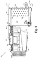
Fig. 2 is a side cross-sectional view of the evaporator ofFig. 1 . -
Fig. 3 is an exploded top perspective view of the components of the evaporator ofFig. 1 . -
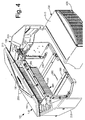
Fig. 4 is an exploded bottom perspective view of the components of the evaporator ofFig. 1 . -
Fig. 5 is a plan view of a fin pattern as may be used with the evaporator ofFig. 1 . -
Fig. 6 is an exploded view of the components of a fan module that may be used in the evaporator ofFig. 1 . -
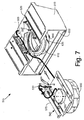
Fig. 7 is an exploded view of the components of an alternative embodiment of a fan module that may be used in the evaporator ofFig. 1 . -
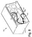
Fig. 8 is a bottom perspective view of the fan module ofFig. 7 . -
Fig. 9 is a perspective view of a replaceable venturi ring as may be used in the fan module ofFig. 7 . -
Fig. 10 is a top plan view of the replaceable venturi ring ofFig. 9 . -
Fig. 11 is a side plan view of the replaceable venturi ring ofFig. 9 . - Referring now to the drawings, in which like numerals refer to like elements throughout the several views,
Figs. 1-4 show anevaporator 100 as may be described herein. Theevaporator 100 may be positioned within acooler 110. Theevaporator 100 typically is positioned on aceiling 115 thereof. Thecooler 110 may be any type of chilled enclosure and may include refrigerators, freezers, or any structure chilled below typical ambient temperatures. Thecooler 110 may have any desired size, shape, or configuration. Theevaporator 100 described herein is in no way limited by the type or design of the cooler 110. Adrain line 120 may extend from theevaporator 100 to the exterior of thecooler 110. Thedrain line 120 may have any desired size, shape, or configuration. Theevaporator 100 may be in communication with other types of refrigeration equipment such as the components of the refrigeration cycle described above and the like. Theoverall evaporator 100 may be modular in nature as will be described in more detail below such that the components thereof may be easily installed and replaced. - The
evaporator 100 includes ahousing 130. Thehousing 130 maybe made in whole or in part out of molded plastics. Metals and other types of substantially rigid materials also may be used as the panel and/or as a backbone-type structure. Thehousing 130 may include atop panel 140, adrain pan 150, and a pair ofside panels 160. Thetop panel 140 may include a number ofmounting brackets 170 attached thereto. Themounting brackets 170 may extend from one end of thetop panel 140. Thetop panel 140 also may have a number ofmounting apertures 180 positioned therein. Themounting brackets 170 and themounting apertures 180 may have any size, shape, or configuration. Thetop panel 140 may be attached to theceiling 115 of thecooler 110 or other structure via themounting brackets 170 and themounting apertures 180 as well as conventional types of fasteners such as bolts and the like. - The
drain pan 150 may have one ormore drain channels 190 formed therein. Thedrain channels 190 may lead to adrain pipe 200 on one end thereof. Thedrain pipe 200 may extend outwardly and slightly downwardly from thedrain pan 150. Thedrain pipe 200 may be in communication with thedrain line 120. Thedrain pan 150 also may have a degree of slope itself leading to thedrain pipe 200. Thedrain pan 150 also may include a raisedlip 210 positioned about a periphery thereof. The raisedlip 210 permits thedrain pan 150 to catch water droplets on the exterior thereof. A submersible pump also may be used herein. Other configurations and other components may be used. - The
side panels 160 may include aservice access panel 220 and anon-service access panel 230. Theservice access panel 220 provides access to the refrigeration components as will be described in more detail below as well as anelectrical module 240. Theelectrical module 240 includes all of the electrical components and controls for the operation of theoverall evaporator 100. Theelectrical module 240 and the other electrical components of theoverall evaporator 100 may be prewired for easy installation. A highvoltage barrier panel 250 may surround theelectrical module 240. A wiring diagram or other types of information may be positioned about theservice access panel 220. Theservice access panel 220 and thenon-service access panel 230 may be hinged for access thereto. Other configurations and other components may be used herein. - A
coil assembly 260 may be mounted onto thetop panel 140 or otherwise. Thecoil assembly 260 may includes a number of tubes with a number of spacedfins 280. Thetubes 270 may extend through a pair ofend plates 290. Thetubes 270 and thefins 280 may be made out of copper, aluminum, or other types of substantially rigid materials with good heat transfer characteristics. Thefins 280 may be corrugated. Other configurations and other components may be used herein. - As is shown in
Fig. 5 , thecoil assembly 260 may have a more open tube design than is typically found in conventional refrigeration units. For example, thetubes 270 may have an outside diameter of about seven (7) millimeters with atube spacing 300 of about twenty-seven (27) millimeters or more and a row spacing 310 of about twenty-three (23) millimeters or more in an off-set fashion. The use of the expandedtube spacing tubes 270 with smaller diameters are positioned closer together. This "closeness", however, tends to aid in the development of frost due to the reduced span therebetween. The tube pattern described herein has smaller tube diameters but maintains the larger spacing such that the building of frost is not increased. The dimensions described herein are for purposes of example only. Other dimensions may be used herein. - The
coil assembly 260 may be in communication with a refrigeration tubing/piping 320. The refrigeration tubing/piping 320 may have any desired size, shape or configuration. The refrigeration tubing/piping 320 may be in communication with other types of refrigeration components such as those described above and the like. Other components and other configurations may be used herein. - The
evaporator 100 also includes a fan module comprising a replaceable venturi ring.Fig. 6 shows afan module 330 including afan housing 340 without such a venturi ring, which will be described below with reference toFigs. 7 and8 . Thefan housing 340 may be made out of molded plastics, metals, and other types of substantially rigid materials. Thefan housing 340 has a number of mountingrails 350 positioned thereon. The mountingrails 350 may mate with a number of top panel rails 360 positioned about thetop panel 140. The use of the mountingrails 350 and the top panel rails 360 allows thefan module 330 as a whole to slide in and out of thehousing 130 of theevaporator 100 as a whole. Afan wiring harness 365 and the like may extend along the top panel rails 360 and/or otherwise within thehousing 130 and may be in communication with thefan module 330 and theelectrical module 240 and/or other controls as thefan module 330 slides therein. - The
fan housing 340 also includes a lockingmember 370 positioned thereon. The lockingmember 370 may be biased into the locked positioned. The lockingmember 370 may mate with a receivingmember 380 positioned about thetop panel 140 or otherwise (including the reverse). When thefan module 330 is slid into thehousing 130 of theevaporator 100, the lockingmember 370 and the receivingmember 380 may cooperate to lock thefan module 330 into place. Other types of locking mechanism may be used herein. - The
fan module 330 includes afan 390 mounted within thefan housing 340. Thefan 390 is a backward incline centrifugal fan. The backward incline centrifugal fan may have an overall reduced height as compared to conventional axial refrigeration fans. A backward incline centrifugal fan generally is used in air handlers as opposed to refrigeration units due to the ability of the fan to overcome high static pressure loads associated with duct work. Thefan 390 may be a variable speed fan. Thefan 390 pulls the airflow through thecoil assembly 260 and turns the flow into the cooler 110 or other refrigerated space. Thefan module 330 also may include afan motor 400, one ormore air plenums 410, and electronic and other controls. The electronics and the other components may be placed in communication with theelectrical module 240 via thewiring harness 365 via one or more quick disconnect fittings or otherwise. Other types offans 390,fan motors 400, and controls may be used herein. Other components and other configurations may be used herein. - The
fan module 330 also includes agrill 420 so as to enclose one end of thehousing 340. Thegrill 420 may be made out of molded plastics, metals, and other types of substantially rigid materials. Thegrill 420 may have any size, shape, or configuration. Thegrill 420 may be attached by a number of clips or other attachment means for easy access thereto and for easy cleaning. - In use, the
evaporator 100 may be attached to theceiling 115 of the cooler 110 or other type of structure. A template may be used to align the location of the mountingbrackets 170 and the mountingapertures 180 so as to drill the appropriate holes and the like. Advantageously, thefan module 330 need not be positioned within thehousing 130. Removing thefan module 330 makes theoverall evaporator 100 lighter and makes attachment to the cooler 110 considerably easier than may be possible with known units. Thecoil assembly 260 and theelectrical module 240 with the related wiring may be premounted to thehousing 130. Once thehousing 130 is installed, thefan module 330 may be slid within thehousing 130 via the mountingrails 350 and the top panel rails 360. The electronics and other controls are prewired such that communication with theelectrical module 340 is established as thefan module 330 slides therein.Multiple fan modules 330 may be used in asingle housing 130. - Access to the
electrical module 340 and thecoil assembly 260 may be provided via theservice access panel 220. Likewise, thefan module 330 may be quickly and easily removed from thehousing 130 for repair, replacement, and/or cleaning. For example, removing thefan module 330 provides access for coil cleaning, drain pan cleaning, and the like. Thefan module 330 may be slid out to an intermediate position or a retracted position or the lockingmember 370 may be released such that thefan module 330 may be removed completely. Thefan module 330 thus may have at least an installed position, a retracted position, and a removed position. Advantageously, thefan module 330 may be removed from thehousing 130 of theevaporator 100 and repaired outside of the cooler 110. - The
evaporator 100 thus provides ease of installation and ease of access with a relatively low profile. For example, if existing evaporators are generally in excess of a height of about fourteen (14) inches (about 35.56 centimeters), the evaporator described herein may be about eleven (11) inches (about 27.94 centimeter) or so. These dimensions are for the purpose of comparison only and any height may be used herein. Nonetheless, theevaporator 100 described herein provides more storage room for the cooler 110 given the reduced profile. Likewise, the risk of injury also may be reduced herein. -
Figs. 7 and8 show afan module 500 having a replaceable venturi ring. Similar to thefan module 330 described above, thefan module 500 also may slide into theevaporator 100. Thefan module 500 thus may include afan housing 510. Thefan housing 510 may be made out of molded plastics, metals, and other types of substantially rigid or semi-rigid materials. Thefan housing 510 may have a number of mountingrails 520 positioned thereon. The mountingrails 520 mate with the top panel rails 360 positioned about thetop panel 140. Afan wiring harness 530 and the like may extend along thefan module 500 and may be in communication with theelectrical module 240 and/or other controls. - The
fan module 500 also may include afan assembly 540. Thefan assembly 540 may include afan 550 and afan motor 560 positioned on afan mounting bracket 570. Thefan 550 is a backward incline centrifugal fan. Thefan 550 may be a variable speed fan. Thefan housing 510 may have afan aperture 580 formed therein. Thefan assembly 540 may be positioned within thefan aperture 580. Thefan mounting bracket 570 may be attached to thefan housing 510 viascrews 590 or other types of conventional fastening means. - The
fan module 500 also may include one ormore air plenums 600. Theair plenums 600 direct the flow of air from thecoil assembly 260 through thefan assembly 540 and into the cooler 110 or other refrigerated space. Other types offans 550,fan motors 560, and controls may be used herein. Other components and other configurations also may be used herein. - The
fan module 500 also includes areplaceable venturi ring 610. Thereplaceable venturi ring 610 may snap into thefan housing 510 and may be positioned about thefan 550. Specifically, thereplaceable venturi ring 610 enhances the efficiency of thefan 550 by forming a venturi thereabout. Specifically, the velocity of the airflow therethrough increases as the cross-sectional area of the flow path decreases through theventuri ring 610. Given such, the respective sizes of thefan 550 and thereplaceable venturi ring 610 may be a significant design consideration. - As is shown in
Figs. 9-11 , thereplaceable venturi ring 610 may have anattachment disk 620 with a number of attachment hooks 630. The attachment hooks 630 may be substantially harpoon like in shape and may snap into a number offan housing apertures 640 formed in thefan housing 510. Although three (3) attachment hooks 630 are shown, any number of attachment hooks 630 may be used herein. Thereplaceable venturi ring 610 may be made out of substantially rigid or semi-rigid plastics and the like. The attachment hooks 630 may have some flexibility in order to be inserted in and removed from thefan housing apertures 640. A number ofattachment disks grooves 650 may be positioned about one or more of the attachment hooks 630 so as to provide additional flexibility (two of which are shown herein). Theventuri ring 610 also may include afan body 660. Thefan body 660 may have a largely taperedshape 670. Thetapered shape 670 of thefan body 660 may match that of thefan housing 510. (SeeFig. 2 with respect to the tapered fan housing 340). Other configurations also may be used herein. - In use, the
replaceable venturi ring 610 may be sized according to the size offan 550 intended to be used therein. Theventuri ring 610 snaps into place within thefan housing 510 via the attachment hooks 630 and thefan housing apertures 640. As described above, theventuri ring 610 creates a venturi therein as the airflow passes therethrough via thefan 550. The use of thereplaceable venturi ring 610 with the appropriate size and configuration thus increases the efficiency of thefan 550 and theoverall evaporator 100. - The
replaceable venturi ring 610 also may be removable from thefan housing 510 and replaceable. As such, thefan assembly 580 may be removed from thefan housing 510 and replaced with a different design and/or size offan 550 or other components. Instead of replacing theentire fan module 500 when changing fan size or design, thereplaceable venturi ring 610 sized for theparticular fan 550 may be inserted within thefan housing 510. As such, retooling of thefan housing 510 may be avoided so as to reduce repair and/or retrofit costs and time. In other words, the existingfan housing 510 may be used with only thereplaceable venturi ring 610 being replaced so as to reduce overall tooling costs and the like.
Claims (12)
- An evaporator (100) for use within a walk-in cooler (110), comprising:a housing (130);the housing mountable within the cooler;a coil assembly (260) mounted within the housing; anda replaceable fan module (330; 500) positionable within the housing when the housing is mounted within the cooler;wherein the replaceable fan module comprises a locking member (370) thereon so as to lock the replaceable fan module within the housing,
and characterized in that:the replaceable fan module comprises a backward incline centrifugal fan (390; 550) mounted therein; andthe replaceable fan module comprises a replaceable venturi ring (610) sized to accommodate the fan. - The evaporator of claim 1, wherein the housing comprises a plastic housing.
- The evaporator of claim 2, wherein the plastic housing comprises a drain pan (150) with one or more drain channels formed therein.
- The evaporator of claim 1, further comprising an electrical module (240) positioned within the housing and in communication with the replaceable fan module.
- The evaporator of claim 1, wherein the coil assembly comprises a plurality of tubes (270) and wherein each of the plurality of tubes comprises a diameter of about seven (7) millimeters.
- The evaporator of claim 5, wherein the plurality of tubes comprises a spacing therebetween of more than about 23 millimeters.
- The evaporator of claim 1, wherein the replaceable fan module comprises a fan housing (340; 510).
- The evaporator of claim 1, wherein the replaceable fan module comprises one or more rails (350, 360; 520) such that the replaceable fan module may slide within the housing.
- The evaporator of claim 1, wherein the fan comprises a multi-speed fan.
- The evaporator of claim 1, wherein the replaceable fan module comprises a grill (420) thereon.
- The evaporator of claim 1, wherein the housing comprises a height of about 30.5 centimeters or less.
- A method of installing an evaporator (100) according to claim 1 within a cooler (110), comprising:attaching an evaporator housing (130) with a coil assembly (260) mounted therein to the cooler;positioning a replaceable fan module (330; 500) into the evaporator housing while the evaporator housing is attached to the cooler; andlocking the fan module in place.
Applications Claiming Priority (3)
| Application Number | Priority Date | Filing Date | Title |
|---|---|---|---|
| US12/969,760 US10041737B2 (en) | 2010-12-16 | 2010-12-16 | Evaporator |
| US13/295,124 US9869505B2 (en) | 2010-12-16 | 2011-11-14 | Evaporator with replaceable fan venturi ring |
| PCT/US2011/065108 WO2012083001A2 (en) | 2010-12-16 | 2011-12-15 | Evaporator |
Publications (2)
| Publication Number | Publication Date |
|---|---|
| EP2652420A2 EP2652420A2 (en) | 2013-10-23 |
| EP2652420B1 true EP2652420B1 (en) | 2016-08-31 |
Family
ID=45478512
Family Applications (1)
| Application Number | Title | Priority Date | Filing Date |
|---|---|---|---|
| EP11808455.7A Active EP2652420B1 (en) | 2010-12-16 | 2011-12-15 | Evaporator |
Country Status (8)
| Country | Link |
|---|---|
| US (1) | US9869505B2 (en) |
| EP (1) | EP2652420B1 (en) |
| CN (1) | CN103261819B (en) |
| AU (1) | AU2011343716B2 (en) |
| BR (1) | BR112013015201B1 (en) |
| CA (1) | CA2821425A1 (en) |
| MX (1) | MX2013006663A (en) |
| WO (1) | WO2012083001A2 (en) |
Families Citing this family (12)
| Publication number | Priority date | Publication date | Assignee | Title |
|---|---|---|---|---|
| US20140110088A1 (en) | 2012-10-24 | 2014-04-24 | Heatcraft Refrigeration Products Llc | Evaporator with Service Clip Configurations |
| CN104260796B (en) * | 2014-09-16 | 2016-08-17 | 芜湖市华益阀门制造有限公司 | A kind of inner surface cleaning machine running gear |
| CN205251291U (en) * | 2015-11-27 | 2016-05-25 | 冯培映 | A barbecue grill equipped with a detachable fan |
| US10588429B2 (en) * | 2015-11-30 | 2020-03-17 | Hill Phoenix, Inc. | Refrigerated case with an induced airflow system |
| CN105650980B (en) | 2016-03-09 | 2018-04-20 | 青岛海尔股份有限公司 | Refrigerator and the branch air-supply arrangement for refrigerator |
| CN105605848B (en) * | 2016-03-09 | 2018-04-20 | 青岛海尔股份有限公司 | Refrigerator and the branch air-supply arrangement for refrigerator |
| US11369118B2 (en) | 2017-04-07 | 2022-06-28 | The Middleby Corporation | Conveyor oven heat delivery system |
| US10416406B1 (en) * | 2018-03-01 | 2019-09-17 | Afl Telecommunications Llc | Communications module housing |
| US11369117B2 (en) * | 2018-12-20 | 2022-06-28 | The Middleby Corporation | Conveyor oven air system |
| JP2022038625A (en) * | 2020-08-27 | 2022-03-10 | 昭和電工株式会社 | Heat exchanger |
| CN112539511B (en) * | 2020-11-30 | 2022-03-29 | 宁波奥克斯电气股份有限公司 | Air conditioner disassembly and washing power-off protection method and device and air conditioner |
| CN112815758B (en) * | 2020-12-30 | 2022-11-04 | 成都威诺电子设备制造有限责任公司 | Intelligent air-cooled radiator |
Family Cites Families (19)
| Publication number | Priority date | Publication date | Assignee | Title |
|---|---|---|---|---|
| US3712078A (en) * | 1971-11-22 | 1973-01-23 | Krispin Eng Ltd | Refrigeration unit |
| US4006390A (en) * | 1975-11-20 | 1977-02-01 | Levine Alfred B | Pocket sized non-lethal electrical weapon |
| US4353680A (en) * | 1979-06-19 | 1982-10-12 | Tokyo Shibaura Denki Kabushiki Kaisha | Exhaust fan with removable face cover |
| US4811569A (en) * | 1988-05-23 | 1989-03-14 | Thermo King Corporation | Zero cube transport refrigeration unit for straight trucks |
| US5588484A (en) * | 1994-08-19 | 1996-12-31 | Emerson Electric Co. | Refrigeration fan system |
| US5531267A (en) * | 1994-08-24 | 1996-07-02 | Emerson Electric Co. | Refrigeration centrifugal blower system |
| US5927389A (en) * | 1997-06-20 | 1999-07-27 | Sun Microsystems, Inc. | Fan tray guide and isolation mount and method |
| US5916253A (en) * | 1998-05-04 | 1999-06-29 | Carrier Corporation | Compact trailer refrigeration unit |
| US5878592A (en) * | 1998-05-20 | 1999-03-09 | Carrier Corporation | Evaporator housing |
| US6182460B1 (en) * | 1998-08-26 | 2001-02-06 | Carrier Corporation | Window room air conditioner |
| US6272876B1 (en) * | 2000-03-22 | 2001-08-14 | Zero Zone, Inc. | Display freezer having evaporator unit |
| US6373698B1 (en) * | 2001-05-03 | 2002-04-16 | International Business Machines Corporation | Apparatus for cooling a computer system |
| US20050095121A1 (en) * | 2003-11-05 | 2005-05-05 | Anand Vithani | Unitary fan-motor grill assembly |
| US6979169B2 (en) * | 2003-11-21 | 2005-12-27 | Broan-Nutone Llc | Modular ventilating exhaust fan assembly and method |
| JP4409976B2 (en) * | 2004-02-03 | 2010-02-03 | 山洋電気株式会社 | Electronic component cooling system |
| WO2005085716A1 (en) * | 2004-03-04 | 2005-09-15 | Lg Electronics Inc. | Indoor unit in air conditioner |
| DE102005057157A1 (en) * | 2005-11-30 | 2007-05-31 | BSH Bosch und Siemens Hausgeräte GmbH | Method for accurately positioning the evaporator in a multiple temperature refrigeration appliance has plastic retaining clips fitted to the upper wall of the evaporator chamber into which the evaporator tubing is fitted |
| DE202007015310U1 (en) * | 2007-06-28 | 2008-11-06 | Liebherr-Hausgeräte Ochsenhausen GmbH | Evaporator module and refrigerator and / or freezer with such an evaporator module |
| US8398183B2 (en) * | 2009-09-21 | 2013-03-19 | Jetmax Ltd. | Hanging hook and modular storage furniture system |
-
2011
- 2011-11-14 US US13/295,124 patent/US9869505B2/en active Active
- 2011-12-15 CN CN201180060757.4A patent/CN103261819B/en not_active Expired - Fee Related
- 2011-12-15 CA CA2821425A patent/CA2821425A1/en not_active Abandoned
- 2011-12-15 BR BR112013015201-0A patent/BR112013015201B1/en not_active IP Right Cessation
- 2011-12-15 EP EP11808455.7A patent/EP2652420B1/en active Active
- 2011-12-15 AU AU2011343716A patent/AU2011343716B2/en not_active Ceased
- 2011-12-15 MX MX2013006663A patent/MX2013006663A/en active IP Right Grant
- 2011-12-15 WO PCT/US2011/065108 patent/WO2012083001A2/en not_active Ceased
Also Published As
| Publication number | Publication date |
|---|---|
| AU2011343716B2 (en) | 2015-11-26 |
| WO2012083001A2 (en) | 2012-06-21 |
| AU2011343716A1 (en) | 2013-07-11 |
| US20120152502A1 (en) | 2012-06-21 |
| US9869505B2 (en) | 2018-01-16 |
| EP2652420A2 (en) | 2013-10-23 |
| BR112013015201B1 (en) | 2020-12-08 |
| BR112013015201A2 (en) | 2016-09-13 |
| MX2013006663A (en) | 2013-07-29 |
| CN103261819A (en) | 2013-08-21 |
| CN103261819B (en) | 2015-11-25 |
| WO2012083001A3 (en) | 2012-09-20 |
| CA2821425A1 (en) | 2012-06-21 |
Similar Documents
| Publication | Publication Date | Title |
|---|---|---|
| US9869505B2 (en) | Evaporator with replaceable fan venturi ring | |
| US10612858B2 (en) | Evaporator | |
| US20240003552A1 (en) | Window-mounted climate control system and method | |
| US10292313B2 (en) | Rackmount cooling system | |
| US10830459B2 (en) | Rain shield for a heat exchanger component | |
| US7185513B2 (en) | Low profile evaporator coil | |
| US20140110088A1 (en) | Evaporator with Service Clip Configurations | |
| US20230213214A1 (en) | Hybrid window air conditioning unit | |
| CN102652248A (en) | Microchannel coil manifold system | |
| US11485497B2 (en) | Divided refrigeration system for aircraft galley cooling | |
| US20190178506A1 (en) | Cooling device for installation under a room ceiling | |
| US10801771B2 (en) | Condenser fan motor mounts and guards | |
| US20180224153A1 (en) | Air conditioning housing system | |
| JP2017138088A (en) | Cooling system for cabinet and cooling cabinet by forced air | |
| EP4036497A1 (en) | Chiller system | |
| US20130167579A1 (en) | Salad Bar Cooler | |
| CN113739501A (en) | Integrated refrigerator for wide-area space | |
| US20120279248A1 (en) | Turbo Coil Refrigeration System | |
| JP2989488B2 (en) | Ceiling-type cooling device | |
| JP4693314B2 (en) | Cooling unit | |
| RU175378U1 (en) | AIR COOLER | |
| JP4632605B2 (en) | Cooling unit | |
| KR20030020477A (en) | A mode of an air cooling cold room refrigeration system without outdoor machine |
Legal Events
| Date | Code | Title | Description |
|---|---|---|---|
| PUAI | Public reference made under article 153(3) epc to a published international application that has entered the european phase |
Free format text: ORIGINAL CODE: 0009012 |
|
| 17P | Request for examination filed |
Effective date: 20130716 |
|
| AK | Designated contracting states |
Kind code of ref document: A2 Designated state(s): AL AT BE BG CH CY CZ DE DK EE ES FI FR GB GR HR HU IE IS IT LI LT LU LV MC MK MT NL NO PL PT RO RS SE SI SK SM TR |
|
| DAX | Request for extension of the european patent (deleted) | ||
| GRAP | Despatch of communication of intention to grant a patent |
Free format text: ORIGINAL CODE: EPIDOSNIGR1 |
|
| RIC1 | Information provided on ipc code assigned before grant |
Ipc: F25D 17/06 20060101AFI20160317BHEP Ipc: F28F 1/32 20060101ALI20160317BHEP Ipc: F28D 1/047 20060101ALI20160317BHEP |
|
| INTG | Intention to grant announced |
Effective date: 20160401 |
|
| GRAS | Grant fee paid |
Free format text: ORIGINAL CODE: EPIDOSNIGR3 |
|
| GRAA | (expected) grant |
Free format text: ORIGINAL CODE: 0009210 |
|
| AK | Designated contracting states |
Kind code of ref document: B1 Designated state(s): AL AT BE BG CH CY CZ DE DK EE ES FI FR GB GR HR HU IE IS IT LI LT LU LV MC MK MT NL NO PL PT RO RS SE SI SK SM TR |
|
| REG | Reference to a national code |
Ref country code: CH Ref legal event code: EP Ref country code: GB Ref legal event code: FG4D |
|
| REG | Reference to a national code |
Ref country code: IE Ref legal event code: FG4D |
|
| REG | Reference to a national code |
Ref country code: DE Ref legal event code: R096 Ref document number: 602011029929 Country of ref document: DE |
|
| REG | Reference to a national code |
Ref country code: AT Ref legal event code: REF Ref document number: 825361 Country of ref document: AT Kind code of ref document: T Effective date: 20161015 |
|
| REG | Reference to a national code |
Ref country code: FR Ref legal event code: PLFP Year of fee payment: 6 Ref country code: LT Ref legal event code: MG4D |
|
| REG | Reference to a national code |
Ref country code: NL Ref legal event code: MP Effective date: 20160831 |
|
| REG | Reference to a national code |
Ref country code: AT Ref legal event code: MK05 Ref document number: 825361 Country of ref document: AT Kind code of ref document: T Effective date: 20160831 |
|
| PG25 | Lapsed in a contracting state [announced via postgrant information from national office to epo] |
Ref country code: NO Free format text: LAPSE BECAUSE OF FAILURE TO SUBMIT A TRANSLATION OF THE DESCRIPTION OR TO PAY THE FEE WITHIN THE PRESCRIBED TIME-LIMIT Effective date: 20161130 Ref country code: HR Free format text: LAPSE BECAUSE OF FAILURE TO SUBMIT A TRANSLATION OF THE DESCRIPTION OR TO PAY THE FEE WITHIN THE PRESCRIBED TIME-LIMIT Effective date: 20160831 Ref country code: RS Free format text: LAPSE BECAUSE OF FAILURE TO SUBMIT A TRANSLATION OF THE DESCRIPTION OR TO PAY THE FEE WITHIN THE PRESCRIBED TIME-LIMIT Effective date: 20160831 Ref country code: LT Free format text: LAPSE BECAUSE OF FAILURE TO SUBMIT A TRANSLATION OF THE DESCRIPTION OR TO PAY THE FEE WITHIN THE PRESCRIBED TIME-LIMIT Effective date: 20160831 Ref country code: FI Free format text: LAPSE BECAUSE OF FAILURE TO SUBMIT A TRANSLATION OF THE DESCRIPTION OR TO PAY THE FEE WITHIN THE PRESCRIBED TIME-LIMIT Effective date: 20160831 |
|
| PG25 | Lapsed in a contracting state [announced via postgrant information from national office to epo] |
Ref country code: ES Free format text: LAPSE BECAUSE OF FAILURE TO SUBMIT A TRANSLATION OF THE DESCRIPTION OR TO PAY THE FEE WITHIN THE PRESCRIBED TIME-LIMIT Effective date: 20160831 Ref country code: AT Free format text: LAPSE BECAUSE OF FAILURE TO SUBMIT A TRANSLATION OF THE DESCRIPTION OR TO PAY THE FEE WITHIN THE PRESCRIBED TIME-LIMIT Effective date: 20160831 Ref country code: SE Free format text: LAPSE BECAUSE OF FAILURE TO SUBMIT A TRANSLATION OF THE DESCRIPTION OR TO PAY THE FEE WITHIN THE PRESCRIBED TIME-LIMIT Effective date: 20160831 Ref country code: NL Free format text: LAPSE BECAUSE OF FAILURE TO SUBMIT A TRANSLATION OF THE DESCRIPTION OR TO PAY THE FEE WITHIN THE PRESCRIBED TIME-LIMIT Effective date: 20160831 Ref country code: LV Free format text: LAPSE BECAUSE OF FAILURE TO SUBMIT A TRANSLATION OF THE DESCRIPTION OR TO PAY THE FEE WITHIN THE PRESCRIBED TIME-LIMIT Effective date: 20160831 Ref country code: GR Free format text: LAPSE BECAUSE OF FAILURE TO SUBMIT A TRANSLATION OF THE DESCRIPTION OR TO PAY THE FEE WITHIN THE PRESCRIBED TIME-LIMIT Effective date: 20161201 |
|
| PG25 | Lapsed in a contracting state [announced via postgrant information from national office to epo] |
Ref country code: EE Free format text: LAPSE BECAUSE OF FAILURE TO SUBMIT A TRANSLATION OF THE DESCRIPTION OR TO PAY THE FEE WITHIN THE PRESCRIBED TIME-LIMIT Effective date: 20160831 Ref country code: RO Free format text: LAPSE BECAUSE OF FAILURE TO SUBMIT A TRANSLATION OF THE DESCRIPTION OR TO PAY THE FEE WITHIN THE PRESCRIBED TIME-LIMIT Effective date: 20160831 |
|
| PG25 | Lapsed in a contracting state [announced via postgrant information from national office to epo] |
Ref country code: PL Free format text: LAPSE BECAUSE OF FAILURE TO SUBMIT A TRANSLATION OF THE DESCRIPTION OR TO PAY THE FEE WITHIN THE PRESCRIBED TIME-LIMIT Effective date: 20160831 Ref country code: BE Free format text: LAPSE BECAUSE OF FAILURE TO SUBMIT A TRANSLATION OF THE DESCRIPTION OR TO PAY THE FEE WITHIN THE PRESCRIBED TIME-LIMIT Effective date: 20160831 Ref country code: SK Free format text: LAPSE BECAUSE OF FAILURE TO SUBMIT A TRANSLATION OF THE DESCRIPTION OR TO PAY THE FEE WITHIN THE PRESCRIBED TIME-LIMIT Effective date: 20160831 Ref country code: CZ Free format text: LAPSE BECAUSE OF FAILURE TO SUBMIT A TRANSLATION OF THE DESCRIPTION OR TO PAY THE FEE WITHIN THE PRESCRIBED TIME-LIMIT Effective date: 20160831 Ref country code: SM Free format text: LAPSE BECAUSE OF FAILURE TO SUBMIT A TRANSLATION OF THE DESCRIPTION OR TO PAY THE FEE WITHIN THE PRESCRIBED TIME-LIMIT Effective date: 20160831 Ref country code: PT Free format text: LAPSE BECAUSE OF FAILURE TO SUBMIT A TRANSLATION OF THE DESCRIPTION OR TO PAY THE FEE WITHIN THE PRESCRIBED TIME-LIMIT Effective date: 20170102 Ref country code: BG Free format text: LAPSE BECAUSE OF FAILURE TO SUBMIT A TRANSLATION OF THE DESCRIPTION OR TO PAY THE FEE WITHIN THE PRESCRIBED TIME-LIMIT Effective date: 20161130 Ref country code: DK Free format text: LAPSE BECAUSE OF FAILURE TO SUBMIT A TRANSLATION OF THE DESCRIPTION OR TO PAY THE FEE WITHIN THE PRESCRIBED TIME-LIMIT Effective date: 20160831 |
|
| REG | Reference to a national code |
Ref country code: DE Ref legal event code: R097 Ref document number: 602011029929 Country of ref document: DE |
|
| PG25 | Lapsed in a contracting state [announced via postgrant information from national office to epo] |
Ref country code: IT Free format text: LAPSE BECAUSE OF FAILURE TO SUBMIT A TRANSLATION OF THE DESCRIPTION OR TO PAY THE FEE WITHIN THE PRESCRIBED TIME-LIMIT Effective date: 20160831 |
|
| PLBE | No opposition filed within time limit |
Free format text: ORIGINAL CODE: 0009261 |
|
| STAA | Information on the status of an ep patent application or granted ep patent |
Free format text: STATUS: NO OPPOSITION FILED WITHIN TIME LIMIT |
|
| REG | Reference to a national code |
Ref country code: CH Ref legal event code: PL |
|
| 26N | No opposition filed |
Effective date: 20170601 |
|
| PG25 | Lapsed in a contracting state [announced via postgrant information from national office to epo] |
Ref country code: SI Free format text: LAPSE BECAUSE OF FAILURE TO SUBMIT A TRANSLATION OF THE DESCRIPTION OR TO PAY THE FEE WITHIN THE PRESCRIBED TIME-LIMIT Effective date: 20160831 |
|
| PG25 | Lapsed in a contracting state [announced via postgrant information from national office to epo] |
Ref country code: MC Free format text: LAPSE BECAUSE OF FAILURE TO SUBMIT A TRANSLATION OF THE DESCRIPTION OR TO PAY THE FEE WITHIN THE PRESCRIBED TIME-LIMIT Effective date: 20160831 |
|
| REG | Reference to a national code |
Ref country code: IE Ref legal event code: MM4A |
|
| PG25 | Lapsed in a contracting state [announced via postgrant information from national office to epo] |
Ref country code: LU Free format text: LAPSE BECAUSE OF NON-PAYMENT OF DUE FEES Effective date: 20161215 Ref country code: CH Free format text: LAPSE BECAUSE OF NON-PAYMENT OF DUE FEES Effective date: 20161231 Ref country code: LI Free format text: LAPSE BECAUSE OF NON-PAYMENT OF DUE FEES Effective date: 20161231 |
|
| PG25 | Lapsed in a contracting state [announced via postgrant information from national office to epo] |
Ref country code: IE Free format text: LAPSE BECAUSE OF NON-PAYMENT OF DUE FEES Effective date: 20161215 |
|
| REG | Reference to a national code |
Ref country code: FR Ref legal event code: PLFP Year of fee payment: 7 |
|
| PG25 | Lapsed in a contracting state [announced via postgrant information from national office to epo] |
Ref country code: HU Free format text: LAPSE BECAUSE OF FAILURE TO SUBMIT A TRANSLATION OF THE DESCRIPTION OR TO PAY THE FEE WITHIN THE PRESCRIBED TIME-LIMIT; INVALID AB INITIO Effective date: 20111215 Ref country code: CY Free format text: LAPSE BECAUSE OF FAILURE TO SUBMIT A TRANSLATION OF THE DESCRIPTION OR TO PAY THE FEE WITHIN THE PRESCRIBED TIME-LIMIT Effective date: 20160831 |
|
| PG25 | Lapsed in a contracting state [announced via postgrant information from national office to epo] |
Ref country code: MK Free format text: LAPSE BECAUSE OF FAILURE TO SUBMIT A TRANSLATION OF THE DESCRIPTION OR TO PAY THE FEE WITHIN THE PRESCRIBED TIME-LIMIT Effective date: 20160831 Ref country code: IS Free format text: LAPSE BECAUSE OF FAILURE TO SUBMIT A TRANSLATION OF THE DESCRIPTION OR TO PAY THE FEE WITHIN THE PRESCRIBED TIME-LIMIT Effective date: 20160831 |
|
| PG25 | Lapsed in a contracting state [announced via postgrant information from national office to epo] |
Ref country code: MT Free format text: LAPSE BECAUSE OF NON-PAYMENT OF DUE FEES Effective date: 20161215 |
|
| PG25 | Lapsed in a contracting state [announced via postgrant information from national office to epo] |
Ref country code: TR Free format text: LAPSE BECAUSE OF FAILURE TO SUBMIT A TRANSLATION OF THE DESCRIPTION OR TO PAY THE FEE WITHIN THE PRESCRIBED TIME-LIMIT Effective date: 20160831 Ref country code: AL Free format text: LAPSE BECAUSE OF FAILURE TO SUBMIT A TRANSLATION OF THE DESCRIPTION OR TO PAY THE FEE WITHIN THE PRESCRIBED TIME-LIMIT Effective date: 20160831 |
|
| PGFP | Annual fee paid to national office [announced via postgrant information from national office to epo] |
Ref country code: GB Payment date: 20251229 Year of fee payment: 15 |
|
| PGFP | Annual fee paid to national office [announced via postgrant information from national office to epo] |
Ref country code: FR Payment date: 20251226 Year of fee payment: 15 |
|
| PGFP | Annual fee paid to national office [announced via postgrant information from national office to epo] |
Ref country code: DE Payment date: 20251229 Year of fee payment: 15 |