EP2650723A1 - Light generation device and light generation method - Google Patents
Light generation device and light generation method Download PDFInfo
- Publication number
- EP2650723A1 EP2650723A1 EP11846888.3A EP11846888A EP2650723A1 EP 2650723 A1 EP2650723 A1 EP 2650723A1 EP 11846888 A EP11846888 A EP 11846888A EP 2650723 A1 EP2650723 A1 EP 2650723A1
- Authority
- EP
- European Patent Office
- Prior art keywords
- light
- incident light
- frequency
- polarized
- resonator structure
- Prior art date
- Legal status (The legal status is an assumption and is not a legal conclusion. Google has not performed a legal analysis and makes no representation as to the accuracy of the status listed.)
- Withdrawn
Links
- 238000000034 method Methods 0.000 title claims description 43
- 230000010287 polarization Effects 0.000 claims abstract description 14
- 239000004038 photonic crystal Substances 0.000 claims description 81
- 229910001218 Gallium arsenide Inorganic materials 0.000 claims description 57
- 239000002131 composite material Substances 0.000 claims description 31
- 230000033228 biological regulation Effects 0.000 claims description 28
- 230000007547 defect Effects 0.000 claims description 4
- 230000001105 regulatory effect Effects 0.000 claims description 4
- 230000001276 controlling effect Effects 0.000 claims description 3
- 230000010355 oscillation Effects 0.000 abstract description 28
- 238000006243 chemical reaction Methods 0.000 description 56
- 238000005086 pumping Methods 0.000 description 25
- 239000010408 film Substances 0.000 description 17
- 230000003287 optical effect Effects 0.000 description 15
- 238000010586 diagram Methods 0.000 description 14
- 239000013078 crystal Substances 0.000 description 12
- 230000000694 effects Effects 0.000 description 10
- 239000000835 fiber Substances 0.000 description 10
- 238000002834 transmittance Methods 0.000 description 8
- 238000000411 transmission spectrum Methods 0.000 description 7
- 238000001228 spectrum Methods 0.000 description 6
- 230000014509 gene expression Effects 0.000 description 5
- 230000005540 biological transmission Effects 0.000 description 3
- 239000000463 material Substances 0.000 description 3
- 229910017680 MgTe Inorganic materials 0.000 description 2
- 238000007796 conventional method Methods 0.000 description 2
- 230000007423 decrease Effects 0.000 description 2
- 230000005684 electric field Effects 0.000 description 2
- 238000003384 imaging method Methods 0.000 description 2
- 230000000737 periodic effect Effects 0.000 description 2
- 239000004576 sand Substances 0.000 description 2
- 239000010409 thin film Substances 0.000 description 2
- 229910000980 Aluminium gallium arsenide Inorganic materials 0.000 description 1
- 229910000530 Gallium indium arsenide Inorganic materials 0.000 description 1
- 229910007709 ZnTe Inorganic materials 0.000 description 1
- 238000000862 absorption spectrum Methods 0.000 description 1
- 239000003795 chemical substances by application Substances 0.000 description 1
- 239000000470 constituent Substances 0.000 description 1
- 239000003814 drug Substances 0.000 description 1
- 238000005516 engineering process Methods 0.000 description 1
- 238000005259 measurement Methods 0.000 description 1
- 230000000704 physical effect Effects 0.000 description 1
- 230000003595 spectral effect Effects 0.000 description 1
- 238000004611 spectroscopical analysis Methods 0.000 description 1
Images









Classifications
-
- G—PHYSICS
- G02—OPTICS
- G02F—OPTICAL DEVICES OR ARRANGEMENTS FOR THE CONTROL OF LIGHT BY MODIFICATION OF THE OPTICAL PROPERTIES OF THE MEDIA OF THE ELEMENTS INVOLVED THEREIN; NON-LINEAR OPTICS; FREQUENCY-CHANGING OF LIGHT; OPTICAL LOGIC ELEMENTS; OPTICAL ANALOGUE/DIGITAL CONVERTERS
- G02F1/00—Devices or arrangements for the control of the intensity, colour, phase, polarisation or direction of light arriving from an independent light source, e.g. switching, gating or modulating; Non-linear optics
- G02F1/35—Non-linear optics
- G02F1/353—Frequency conversion, i.e. wherein a light beam is generated with frequency components different from those of the incident light beams
- G02F1/3534—Three-wave interaction, e.g. sum-difference frequency generation
-
- G—PHYSICS
- G02—OPTICS
- G02F—OPTICAL DEVICES OR ARRANGEMENTS FOR THE CONTROL OF LIGHT BY MODIFICATION OF THE OPTICAL PROPERTIES OF THE MEDIA OF THE ELEMENTS INVOLVED THEREIN; NON-LINEAR OPTICS; FREQUENCY-CHANGING OF LIGHT; OPTICAL LOGIC ELEMENTS; OPTICAL ANALOGUE/DIGITAL CONVERTERS
- G02F2203/00—Function characteristic
- G02F2203/13—Function characteristic involving THZ radiation
Definitions
- the present invention relates to a light generation device and a light generation method.
- Terahertz waves are considered applicable to various physical property measurements utilizing spectroscopy and imaging techniques employing characteristics of the terahertz waves, and their field of application has been extending over a very wide range of industry, medicine, agriculture, biotechnology, security, and the like. Therefore, much attention has been focused on how to improve techniques for generating the terahertz waves.
- Non Patent Literature 1 As methods for generating terahertz waves by using nonlinear optical crystals, various methods such as those utilizing birefringence (see, for example, the following Non Patent Literature 1), quasi-phase matching (see, for example, the following Non Patent Literature 2), double resonator (see, for example, the following Non Patent Literature 3), and parametric oscillation have been proposed.
- Non Patent Literatures 1 to 3 are not considered realistic as methods for generating light having a desirable frequency, since they mostly use laser light having a high intensity on the order of GW/cm 2 as a pumping light source, employ pulsed light which is hard to narrow its linewidth, make a device bulky in principle, or yield a low efficiency in light generation.
- Non Patent Literatures 1 to 3 use pulsed light for pumping light sources, and none of them is evaluated as a continuous light source. Continuous light is superior to pulsed light in spectral resolution of frequency regions. Therefore, light sources for continuous light are demanded in the market, though those satisfying market demands such as frequency-variable regions, generation intensity, and smaller size are few.
- the light generation device of the present invention comprises a resonator structure for intensifying incident light and outputting the intensified light and an input unit for inputting the incident light into the resonator structure; wherein the incident light comprises first and second incident light components having polarization states different from each other and frequencies different from each other; wherein the input unit inputs the first and second incident light components at an angle inclined from a direction perpendicular to a principal surface in the resonator structure; and wherein the resonator structure outputs light having a frequency corresponding to a difference between the respective frequencies of the first and second incident light components.
- the light generation method of the present invention comprises, in a light generation device comprising a resonator structure for intensifying incident light and outputting the intensified light and an input unit for inputting the incident light into the resonator structure, the incident light comprising first and second incident light components having polarization states different from each other and frequencies different from each other, inputting, by the input unit, the first and second incident light components at an angle inclined from a direction perpendicular to a principal surface in the resonator structure and outputting, by the resonator structure, light having a frequency corresponding to a difference between the respective frequencies of the first and second incident light component.
- the light generation device comprises a resonator structure and an input unit; when the input unit inputs first and second incident light components at an angle with a principal surface in the resonator structure, the resonator structure outputs light having a frequency corresponding to a difference between the respective frequencies of the first and second incident light components as output light.
- the two incident light components have polarization states different from each other; for example, the first and second incident light components have s- and p-polarized states, respectively.
- the first and second incident light components may have p- and s-polarized states, respectively.
- the two incident light components have respective frequencies different from each other; preferably, the s- and p-polarized incident light components have frequencies coinciding with resonance frequencies of s- and p-polarized light components corresponding to the inclination angle of the input unit, respectively.
- the resonance frequency is meant herein a frequency which can generate a resonator mode, and is not limited to one frequency value but may be a frequency band having some width which generates the resonator mode.
- the input unit inputs the incident light with an angle, whereby a shift occurs in the resonance frequency of the resonator structure for differently polarized light components.
- the present invention provides a frequency-variable light generation device and light generation method.
- the device and method can also improve the efficiency in light generation and reduce the size of the device as a whole.
- the present invention may further comprise a temperature regulation unit for controlling the resonance frequencies of the s- and p-polarized light components by regulating a temperature of the resonator structure.
- regulating the temperature of the resonator structure can control the resonance frequencies of the s- and p-polarized light components, so that one of the resonance frequencies becomes constant.
- the temperature regulation is considered to be a relatively easy control technique and thus can improve the convenience of the device structure.
- the resonator structure may be a simple resonator structure comprising a defect layer constituted by a GaAs layer and a reflector constituted by a multilayer comprising GaAs and AlAs layers.
- the resonator structure may be a composite photonic crystal structure comprising a photonic crystal constituted by a multilayer comprising active and inactive layers respectively made of GaAs and AlAs layers and a reflector constituted by a multilayer comprising GaAs and AlAs layers.
- the resonator structure may be a simple photonic crystal structure comprising a photonic crystal constituted by a multilayer comprising active and inactive layers respectively made of GaAs and AlAs layers.
- the GaAs and AlAs layers in the reflector in the composite photonic crystal structure may have respective thicknesses different from each other.
- the effective thickness ratio of the GaAs layer to the AlAs layer 1:1 in the photonic crystal and 1:4 in the reflector, so that the photonic crystal and reflector may have effective thickness ratios different from each other.
- the resonator structure may output light having a frequency corresponding to the difference between the respective resonance frequencies of the s- and p-polarized light components having different values as a result of structural birefringence caused by the input unit inputting the first and second incident light components at the inclined angle.
- the present invention can provide a light generation device and light generation method which can efficiently generate light having a desirable frequency.
- Fig. 1 is a schematic structural diagram of the terahertz light generation device 1.
- the terahertz light generation device 1 mainly comprises laser oscillation units 10, 11 (corresponding to the "input unit” in claims), a resonator structure 12, and a temperature regulator 13 (corresponding to the "temperature regulation unit” in the claims).
- the laser oscillation units 10, 11 feed the resonator structure 12 with incident light through a mirror 14 and a lens 15.
- the resonator structure 12 intensifies the incident light fed from the laser oscillation units 10, 11 and outputs thus intensified light as output light.
- the light incident on the resonator structure 12 from the laser oscillation units 10, 11 comprises two incident light components, i.e., first and second incident light components.
- the two incident light components have polarization states different from each other; for example, the first and second incident light components may have sand p-polarized states, respectively, or vice versa.
- the first and second incident light components having the s- and p-polarized states are made incident on the resonator structure 12 by the laser oscillation units 10, 11, respectively.
- the laser oscillation units 10, 11 feed the resonator structure 12 with the first and second incident light components at an angle inclined from a direction perpendicular to a principal surface in the resonator structure 12.
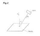
- Fig. 2 images how the laser oscillation units 10, 11 feed the resonator structure 12 with the first and second incident light components at an angle.
- the laser oscillation units 10, 11 feed the resonator structure 12 with the first and second incident light components in a direction D2 which is inclined by an angle ⁇ from a direction D1 which is perpendicular to a principal surface 12a in the resonator structure 12.
- the laser oscillation units 10, 11 make the first and second incident light components incident obliquely at the same angle, while adjusting the inclination angle ⁇ within the range of 0° to 90°.
- a shift occurs in a frequency which generates a resonator mode (hereinafter also referred to as "resonance frequency", the resonance frequency is not limited to one frequency value but may be a frequency band having some width which generates the resonator mode).
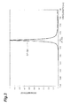
- Figs. 3 and 4 image this as transmittance vs. wavelength.
- graphs G1 and G2 represent respective cases where the laser oscillation units 10, 11 feed the resonator structure 12 with the first and second incident light components respectively in the s- and p-polarized states perpendicular to the principal surface 12a therein.
- the resonance frequency in the graph G1 of the s-polarized first incident light component is a frequency corresponding to a wavelength H1 (e.g., 1064 nm), while the resonance frequency in the graph G2 of the p-polarized second incident light component is a frequency corresponding to a wavelength H2 (e.g., 1064 nm).
- graphs G3 and G4 represent respective cases where the laser oscillation units 10, 11 feed the resonator structure 12 with the first and second incident light components respectively in the s- and p-polarized states at an angle of 15° with the principal surface 12a therein.
- the resonance frequency in the graph G3 of the s-polarized first incident light component is a frequency corresponding to a wavelength H3, while the resonance frequency in the graph G4 of the p-polarized second incident light component is a frequency corresponding to a wavelength H4.
- the perpendicular incidence no shift in resonance frequency occurs between the s- and p-polarized light components as illustrated in Fig. 3 . That is, the wavelengths H1 and H2 coincide with each other.
- Fig. 3 represents the graphs G1 and G2 superimposed on each other.
- a shift occurs in resonance frequency, which is represented by Z1 in Fig. 4.
- Figs. 3 and 4 are respective cases where the incidence angle ⁇ is 0° and 15° while employing a simple photonic crystal 123 as the resonator structure 12 in Structural Example 3 which will be explained later.
- the output light of the terahertz light generation device 1 in the first embodiment has a frequency corresponding to the shift Z1 illustrated in Fig. 4 unless temperature regulation which will be described later is performed.
- the two incident light components fed to the resonator structure 12 by the laser oscillation units 10, 11 have respective frequencies different from each other.
- the frequency of the s-polarized first incident light component coincides with the resonance frequency of s-polarized light corresponding to the inclination angle ⁇ of the laser oscillation unit 10
- the frequency of the p-polarized second incident light component coincides with the resonance frequency of p-polarized light corresponding to the inclination angle ⁇ of the laser oscillation unit 11.
- the transmittance for s-polarized light reaches its peak at the wavelength H3, whereby the s-polarized first incident light component has a frequency corresponding to the wavelength H3.
- the transmittance for p-polarized light reaches its peak at the wavelength H4, whereby the p-polarized second incident light component has a frequency corresponding to the wavelength H4.
- the wavelength H4 was 1060.85 nm in the simple resonator of Structural Example 1, 1060.4 nm in the composite photonic crystal of Structural Example 2, and 1060.15 nm in the simple photonic crystal of Structural Example 3.
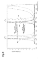
- Fig. 5 is a chart illustrating how a change occurs in the resonance frequency under temperature regulation in the situation of Fig. 4 .
- v1 the frequency corresponding to the wavelength H5
- v2 the frequency corresponding to the wavelength H6
- the frequency of output light is their difference
- the temperature regulator 13 When the incidence angle ⁇ is made greater, the frequency of the resonator mode shifts to the high frequency side.
- the above-mentioned Figs. 3 and 4 represent this fact. Therefore, in order to return the shifted resonance frequency to the original resonance frequency, the temperature regulator 13 performs temperature regulation for the resonator structure 12, so as to control its refractive index. This controls the respective resonance frequencies of the s- and p-polarized first and second incident light components so that one of the resonance frequencies becomes constant.
- the resonance frequency of the p-polarized second incident light component is controlled so as to return to the resonance frequency in the state where the incidence angle is zero (in the perpendicular incidence state) and become constant.
- the resonance frequency of the s-polarized first incident light component changes from the wavelength H3 to the wavelength H5 after the temperature regulation.
- the temperature regulation also changes the resonance frequency of the p-polarized second incident light component (the frequency corresponding to the wavelength H4) to the wavelength H6.
- the wavelength H6 is a wavelength coinciding with or near the resonance frequency at the time of perpendicular incidence (frequencies corresponding to the wavelengths H1 and H2; see Figs. 3 and 4 ).
- the difference in frequency corresponding to the difference in wavelength represented by Z2 in Fig. 5 becomes the frequency of the output light of the terahertz light generation device 1 in the first embodiment.
- the difference in frequency corresponding to the difference in wavelength represented by Z1 in Figs. 4 and 5 becomes the frequency of the output light of the terahertz light generation device 1 in the first embodiment as mentioned above.
- the range of temperature regulation at this time is 220 K to 390 K, for example.
- the range of temperature regulation varies depending on the resonator structure in use, i.e., the number of films, film thicknesses, and materials in the resonator structure.
- the following expressions (1) and (2) illustrate temperature dependences of refractive index.
- the expression (1) illustrates the temperature dependence of refractive index at a part constituted by GaAs in the case where the resonator structure 12 includes the part constituted by GaAs.
- the expression (2) illustrates the temperature dependence of refractive index at a part consituted by AlAs in the case where the resonator structure 12 includes the part constituted by AlAs.
- n and T indicate the refractive index and the temperature of the resonator structure 12, respectively.
- d n d T GaAs 2.67 ⁇ 10 - 4 1 / K
- d n d T AlAs 1.43 ⁇ 10 - 4 1 / K
- Reference Literature 1 is one concerning a technique for performing frequency control under temperature regulation.
- Reference Literature 1 J. Talghader and J. S. Smith, Appl. Phys. Lett. 66, 335, 1995
- the resonator structure 12 inputs thereto the s-polarized first incident light component having the frequency v1 as signal light and the p-polarized second incident light component having the frequency v2 as pumping light from the laser oscillation units 10, 11, respectively, and issues output light having a frequency corresponding to the difference between the respective frequencies of the incident light components, i.e.,
- the laser oscillation units 10, 11 feed the resonator structure 12 with the s-polarized first incident light component as signal light and the p-polarized second incident light component as pumping light at the inclined angle ⁇ , so as to cause structural birefringence, whereby the resonator structure 12 outputs light having a frequency corresponding to the difference between the respective resonance frequencies of the sand p-polarized light components resultantly having different values.
- the resonator structure 12 outputs light in a terahertz region as idler light according to the following Structural Examples 1 to 3.
- the first structural example relates to a case employing a simple resonator as the resonator structure 12.
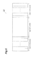
- Fig. 6 is a conceptual diagram of the simple resonator 121 in this case.
- the simple resonator 121 has a structure comprising a defect layer constituted by a GaAs layer and a reflector (DBR: Distributed Bragg Reflector) constituted by a multilayer composed of GaAs and AlAs layers.
- DBR Distributed Bragg Reflector
- the flowchart of Fig. 7 illustrates a procedure of generating output light in a desirable terahertz region by using the terahertz light generation device 1 equipped with thus constructed simple resonator 121.
- a wavelength of a terahertz wave to be generated is determined according to its use (step S1).
- the kind of resonator structure 12 is determined (step S2).
- the simple resonator 121 is assumed to be chosen in this structural example.
- the incidence angle ⁇ of the s-polarized first incident light component (signal light) and p-polarized second incident light component (pumping light) is determined according to the frequency of the terahertz wave to be generated (step S3).
- the incidence angle ⁇ is determined by the frequency of light to be generated;
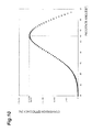
- Fig. 8 illustrates the relationship between the incidence angle ⁇ and the frequency of light to be generated when the simple resonator 121 is chosen as the resonator structure 12.
- the incidence angle ⁇ can be set to 65° as illustrated in Fig. 8 .
- the frequency and intensity of pumping light, the frequency and intensity of signal light, and the temperature of the simple resonator 121 are determined (step S4).
- the frequency of pumping light is kept constant at about 281.95 THz (wavelength: 1064 nm), and its intensity is set to 1 MW/cm 2 .
- the intensity is desirably as high as possible in view of conversion efficiency.
- the frequency of signal light can be determined by 281.95 THz - the difference frequency (the frequency of light to be generated) and thus is set to about 281.64 THz.
- the intensity of signal light is on a par with or lower than the intensity of pumping light.
- the temperature of the simple resonator 121 can be set to 340 K as an absolute temperature as illustrated in Fig. 9 .
- the frequency of pumping light is kept constant at about 281.95 THz (wavelength: 1064 nm) as mentioned above under temperature regulation.
- Fig. 10 illustrates the conversion efficiency at this time.
- the conversion efficiency is 2.1e-006%.
- the conversion efficiency rises as the incidence angle ⁇ is made greater, so that the maximum value of conversion efficiency appears in the vicinity of 65°.
- Fig. 10 represents 2.1e-006% as the maximum conversion efficiency since the confinement effect is weakened in view of performances of readily usable laser light sources at present, a higher conversion efficiency value can be obtained by changing conditions.
- Examples of merits in this structural example include: 1. thinness in the device; 2. variable generation frequency; and 3. achievability of a high-output continuous light source.
- the device i.e., the resonator structure 12
- the device of this structural example can be considered to be one having performances beyond comparison.
- the device of Non Patent Literature 3, whose structure is totally different from that of this structural example and cannot be compared therewith, seems to be on the same order as with this structural example only in terms of the thickness of the resonator structure.
- the same literature has not yet reached discussions of conversion efficiency, so that its conversion efficiency cannot be compared with that in the device of this structural example.
- this structural example seems to be superior to the literature beyond comparison in terms of conversion efficiency when their conditions such as incident light intensity and element thickness are made equivalent to each other.
- the output in photomixing decreases in the unit of digits as the frequency becomes higher
- the output in the first embodiment does not decrease so much even in the frequency region of 0.5 to 3.0 THz.
- the linewidth of thus generated terahertz light seems to be on substantially the same order as that of the pumping light or signal light.
- the structural example in the first embodiment assumes a linewidth on the order of GHz, continuous light sources on the order of kHz and MHz are commercially available at present, whereby designs conforming thereto are expected to further raise the conversion efficiency.
- Even the current structural example can generate light having the same order of linewidth.
- the value of conversion efficiency may become higher than the above-mentioned value depending on structural differences in the resonator structure 12 (differences in the structure itself as will be illustrated by the following Structural Examples 2 and 3 and differences in the growth face).
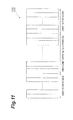
- Fig. 11 is a conceptual diagram of the composite photonic crystal structure 122 in this case.
- the composite photonic crystal structure 122 has a structure comprising a photonic crystal constituted by a multilayer composed of active and inactive layers respectively made of GaAs and AlAs layers and a reflector (DBR) constituted by a multilayer of GaAs and AlAs layers.
- DBR reflector
- Parameters in the composite photonic crystal structure 122 are listed in the following.
- a wavelength of a terahertz wave to be generated is determined according to its use (step S1).
- the kind of resonator structure 12 is determined (step S2).
- the composite photonic crystal structure 122 is assumed to be chosen in this structural example.
- the incidence angle ⁇ of the s-polarized first incident light component (signal light) and p-polarized second incident light component (pumping light) is determined according to the frequency of the terahertz wave to be generated (step S3).
- the incidence angle ⁇ is determined by the frequency of light to be generated;
- Fig. 12 illustrates the relationship between the incidence angle ⁇ and the frequency of light to be generated when the composite photonic crystal structure 122 is chosen as the resonator structure 12.
- the incidence angle ⁇ can be set to 67° as illustrated in Fig. 12 .
- the frequency and intensity of pumping light, the frequency and intensity of signal light, and the temperature of the composite photonic crystal structure 122 are determined (step S4).
- the frequency of pumping light is kept constant at about 281.95 THz (wavelength: 1064 nm), and its intensity is set to 1 MW/cm 2 .
- the intensity is desirably as high as possible in view of conversion efficiency.
- the frequency of signal light can be determined by 281.95 THz - the difference frequency (the frequency of light to be generated) and thus is set to about 280.4 THz.
- the intensity of signal light is on a par with or lower than the intensity of pumping light.
- the temperature of the composite photonic crystal structure 122 can be set to 380 K as an absolute temperature as illustrated in Fig. 13 .
- the frequency of pumping light is kept constant at about 281.95 THz (wavelength: 1064 nm) as mentioned above under temperature regulation.
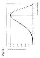
- Fig. 14 illustrates the conversion efficiency at this time.
- the conversion efficiency is 6e-005%.
- the conversion efficiency rises as the incidence angle ⁇ is made greater, so that the maximum value of conversion efficiency appears in the vicinity of 67°.
- Fig. 14 represents 6e-005% as the maximum conversion efficiency since the confinement effect is weakened in view of performances of readily usable laser light sources at present, a higher conversion efficiency value can be obtained by changing conditions. Superior points of this structural example, which are the same as those mentioned in Structural Example 1, will not be described.
- Fig. 15 is a conceptual diagram of the composite photonic crystal structure 123 in this case.
- the simple photonic crystal 123 has a structure comprising a photonic crystal constituted by a multilayer composed of active and inactive layers respectively made of GaAs and AlAs layers.
- a wavelength of a terahertz wave to be generated is determined according to its use (step S1).
- the kind of resonator structure 12 is determined (step S2).
- the simple photonic crystal 123 is assumed to be chosen in this structural example.
- the incidence angle ⁇ of the s-polarized first incident light component (signal light) and p-polarized second incident light component (pumping light) is determined according to the frequency of the terahertz wave to be generated (step S3).
- the incidence angle ⁇ is determined by the frequency of light to be generated;
- Fig. 16 illustrates the relationship between the incidence angle ⁇ and the frequency of light to be generated when the simple photonic crystal 123 is chosen as the resonator structure 12.
- the incidence angle ⁇ can be set to 85° as illustrated in Fig. 16 .
- the frequency and intensity of pumping light, the frequency and intensity of signal light, and the temperature of the simple photonic crystal 123 are determined (step S4).
- the frequency of pumping light is kept constant at about 281.95 THz (wavelength: 1064 nm), and its intensity is set to 1 MW/cm 2 .
- the intensity is desirably as high as possible in view of conversion efficiency.
- the frequency of signal light can be determined by 281.95 THz - the difference frequency (the frequency of light to be generated) and thus is set to about 278.95 THz.
- the intensity of signal light is on a par with or lower than the intensity of pumping light.
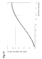
- the temperature of the simple photonic crystal 123 can be set to 420 K as an absolute temperature as illustrated in Fig. 17 .
- the frequency of pumping light is kept constant at about 281.95 THz (wavelength: 1064 nm) as mentioned above under temperature regulation.
- Fig. 18 illustrates the conversion efficiency at this time.
- the conversion efficiency is 3.9e-005%.
- the conversion efficiency rises as the incidence angle ⁇ is made greater, so that the maximum value of conversion efficiency appears in the vicinity of 85°.
- Fig. 18 represents 3.9e-005% as the maximum conversion efficiency since the confinement effect is weakened in view of performances of readily usable laser light sources at present, a higher conversion efficiency value can be obtained by changing conditions. Superior points of this structural example, which are the same as those mentioned in Structural Example 1, will not be described.
- the terahertz light generation device 1 of the first embodiment generates terahertz waves by using the GaAs/AlAs resonator structure 12.
- the terahertz light generation device 1 of the first embodiment When light is incident on the resonator structure 12 at an angle, its transmittance spectrum shifts as the angle increases, while a difference occurs in the width of shifting frequency between the s- and p-polarized light components (see Fig. 3 ). This is considered to be a phenomenon occurring because of structural birefringence caused by a periodic thin film structure and attributable to the fact that the effective refractive index is changed by polarization.
- the terahertz light generation device 1 of the first embodiment can be utilized as a frequency-variable terahertz light source.
- the resonator structure 12 in the terahertz light generation device 1 in the first embodiment has a crystal length of several tens of micrometers at the longest. This can reduce the size of the device as a whole, whereby the terahertz light generation device 1 of the first embodiment can be employed as a highly versatile terahertz light source.
- the laser oscillation units 10, 11 feed the resonator structure 12 with the first and second incident light components at the same angle, while the temperature regulator 13 performs temperature regulation for the resonator structure 12.
- This controls the respective resonance frequencies of the s- and p-polarized light components, so that one of the resonance frequencies becomes constant.
- the temperature regulation is considered to be a relatively easy control technique and thus can improve the convenience of the device structure.
- the second embodiment of the present invention will now be explained.
- differences between the second embodiment and Structural Example 2 of the first embodiment will mainly be explained while omitting their common features as much as possible.
- the effective thickness ratio of GaAs layer to AlAs layer in Structural Example 2 of the first embodiment is as follows.
- the effective thickness is a value obtained by multiplying film thickness by refractive index.
- the second embodiment employs a composite photonic crystal structure as the resonator structure 12 of Fig. 1 as with Structural Example 2 of the first embodiment but differs therefrom in film thickness in the DBR part.
- Fig. 19 is a conceptual diagram of the composite photonic crystal structure 124 in the second embodiment.
- the composite photonic crystal structure 124 has a structure comprising a photonic crystal constituted by a multilayer composed of active and inactive layers respectively made of GaAs and AlAs layers and a reflector (DBR) constituted by a multilayer of GaAs and AlAs layers.
- DBR reflector
- Parameters in the composite photonic crystal structure 124 are listed in the following.
- the effective thickness ratio of GaAs layer to AlAs layer in the second embodiment is as follows:
- the respective effective thicknesses of GaAs and AlAs layers coincide with each other in the photonic crystal part, but differ from each other and yield a ratio of 1:4 in the DBR part.
- Making the GaAs and AlAs layers have respective effective thicknesses different from each other, i.e., varying the effective thickness ratio between the GaAs and AlAs layers, can change the frequency difference ⁇ between the respective transmission peaks of the p- and s-polarized light components (corresponding to Z1 and Z2 in Figs. 4 and 5 ).
- Fig. 20 illustrates this fact; in Fig. 20(A) , X in the abscissa and the ordinate indicate the effective thickness ratio and ⁇ , respectively.
- graphs G7 and G9 indicate transmission spectra of the s-polarized light component
- graphs G8 and G10 indicate transmission spectra of the p-polarized light component.
- X in Fig. 20 indicates the effective thickness ratio
- the thickness ratio not multiplied by the refractive index exhibits a similar behavior of ⁇ , whereby the effective thickness ratio will simply be referred to as thickness ratio in the following explanation.
- Fig. 21 is a set of charts for explaining differences in transmittance spectra between Structural Example 2 of the first embodiment and the second embodiment.
- Fig. 21(A) illustrates the case of Structural Example 2 of the first embodiment
- Fig. 21(B) illustrates the case of the second embodiment.
- PC photonic crystal
- Structural Example 2 of the first embodiment in Fig. 21 (A) uses a thickness ratio of 1:1
- the second embodiment in Fig. 21 (B) uses a thickness ratio of 1:4, for example, such that one is thicker than the other.
- Fig. 21 is a set of charts for explaining differences in transmittance spectra between Structural Example 2 of the first embodiment and the second embodiment.
- Fig. 21(A) illustrates the case of Structural Example 2 of the first embodiment
- Fig. 21(B) illustrates the case of the second embodiment.
- Each of them constructs the photonic crystal (PC) at the thickness ratio of 1:1 and uses the largest ⁇ .
- graphs G11, G13, G15, G17, G19, and G21 illustrate transmission spectra of the s-polarized light component
- graphs G12, G14, G16, G18, G20, and G22 illustrate transmission spectra of the p-polarized light component.
- the DBR exhibits high reflectance at a PC peak wavelength ⁇ 1 of the p-polarized light component (the PC peak wavelength ⁇ 1 of the p-polarized light component corresponds to the center part of a depression of the graph G14, i.e., the center part of the photonic bandgap) and at a PC peak wavelength ⁇ 2 of the s-polarized light component (the PC peak wavelength ⁇ 2 of the s-polarized light component corresponds to the center part of a depression of the graph G13, i.e., the center part of the photonic bandgap) and thus has about the same reflectance for both the p- and s-polarized light components.
- the DBR exhibits high reflectance at a PC peak wavelength ⁇ 3 of the p-polarized light component (the PC peak wavelength ⁇ 3 of the p-polarized light component corresponds to the center part of a depression of the graph G20, i.e., the center part of the photonic bandgap) and low reflectance at a PC peak wavelength ⁇ 4 of the s-polarized light component (the PC peak wavelength ⁇ 4 of the s-polarized light component does not correspond to the center part of a depression of the graph G19, i.e., the center part of the photonic bandgap) and thus has a high confinement effect only for the p-polarized light component.
- Structural Example 2 of the first embodiment in Fig. 21(A) yields a large difference
- the second embodiment in Fig. 21(B) yields a small difference
- the full width at half maximum (FWHM) is a value indicating a difference in wavelength (frequency) which is 0.5 times the peak value of a transmission peak.
- Fig. 22 is a set of charts illustrating operations at low-angle incidence and high-angle incidence in the second embodiment.
- Figs. 22(A) and 22(B) illustrate the respective cases of low-angle incidence and high-angle incidence.
- the PC peak wavelengths ( ⁇ 5, ⁇ 6) of p- and s-polarized light components are located in a high reflection part of the DBR, whereby the DBR exhibits high reflectance for both of them.
- the DBR exhibits high reflectance at the PC peak wavelength ⁇ 7 of the p-polarized light component and low reflectance at the PC peak wavelength ⁇ 8 of the s-polarized light component.
- Structural Example 2 of the first embodiment may enhance and reduce confinement effects for the p- and s-polarized light components, respectively, as the angle increases, so that only the s-polarized light component can be utilized well
- the second embodiment adjusts the thickness ratio between the GaAs and AlAs layers and thus can keep an appropriate full width at half maximum, thereby making it possible to keep the best full width at half maximum either at low or high angle.
- graphs G23, G25, G27, G29, G31, and G33 illustrate transmission spectra of the s-polarized light component
- graphs G24, G26, G28, G30, G32, and G34 illustrate transmission spectra of the p-polarized light component.
- a wavelength of a terahertz wave to be generated is determined according to its use (step S1).
- the kind of resonator structure 12 is determined (step S2).
- the composite photonic crystal structure 124 is assumed to be chosen in this structural example.
- the incidence angle ⁇ of the s-polarized first incident light component (signal light) and p-polarized second incident light component (pumping light) is determined according to the frequency of the terahertz wave to be generated (step S3).
- the incidence angle ⁇ is determined by the frequency of light to be generated;
- Fig. 23 illustrates the relationship between the incidence angle ⁇ and the frequency of light to be generated when the composite photonic crystal structure 124 is chosen as the resonator structure.
- the incidence angle ⁇ can be set to 40° as illustrated in Fig. 23 .
- the difference ( ⁇ ) between the respective transmittance spectra of the p- and s-polarized light components becomes greater, thereby making the generation frequency higher.
- the frequency and intensity of pumping light, the frequency and intensity of signal light, and the temperature of the composite photonic crystal structure 124 are determined (step S4).
- the frequency of pumping light is kept constant at about 281.95 THz (wavelength: 1064 nm), and its intensity is set to 1 MW/cm 2 .
- the intensity is desirably as high as possible in view of conversion efficiency.
- the frequency of signal light can be determined by 281.95 THz - the difference frequency (the frequency of light to be generated) and thus is set to about 280.85 THz.
- the intensity of signal light is on a par with or lower than the intensity of pumping light.
- the temperature of the composite photonic crystal structure 124 can be set to 290 K as an absolute temperature as illustrated in Fig. 24 .
- the frequency of pumping light is kept constant at about 281.95 THz (wavelength: 1064 nm) as mentioned above under temperature regulation.
- the shift in transmittance spectra becomes greater, thereby making it necessary to change the sample temperature correspondingly.
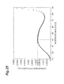
- Fig. 25 illustrates the conversion efficiency at this time. As illustrated in Fig. 25 , when the incidence angle ⁇ is 40° while the composite photonic crystal structure 122 is under temperature regulation at 290 K, the conversion efficiency is 1.8e-003%. It is seen to achieve an improvement in conversion efficiency by two digits or more when compared with the results of Structural Example 2 of the first embodiment illustrated in Fig. 14 .
- Fig. 26 is a chart for illustrating the conversion efficiency in Structural Example 2 of the first embodiment and that in the second embodiment in comparison with each other. Graphs G35 and G36 illustrate the respective conversion efficiencies in Structural Example 2 of the first embodiment and the second embodiment. The conversion efficiency in the second embodiment is seen to be higher than that in Structural Example 2 of the first embodiment at all the incidence angles. For convenience in representation, Fig. 26 indicates the conversion efficiency in a log scale.
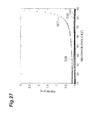
- Fig. 27 is a chart for illustrating the full width at half maximum in Structural Example 2 of the first embodiment and that in the second embodiment in comparison with each other.
- Graphs G37 and G38 illustrate the respective full widths at half maximum of the p-and s-polarized light components in Structural Example 2 of the first embodiment
- graphs G39 and G40 illustrate the respective full widths at half maximum of the p- and s-polarized light components in the second embodiment.
- the full width at half maximum in each of the polarized light components is near the ideal full width at half maximum of 0.01 [nm] and only 0.055 [nm] at the maximum.
- Fig. 28 is a chart illustrating the full width at half maximum comparison in a log scale for convenience in representation. In conformity to Fig. 27 , the same numbers are used in the graphs.
- the difference in full width at half maximum between the p- and s-polarized light components becomes greater as the incidence angle increases (see graphs G37' and G38').
- the difference in full width at half maximum between the p- and s-polarized light components is small even when the incidence angle is large (see graphs G39' and G40').
- both of the p- and s-polarized light components can enter the inside of the crystal even at higher angle, thereby contributing to terahertz wave generation. Since the p- and s-polarized light components have small full widths at half maximum, the electric field enhancement effect within the crystal is so high that an increase in conversion efficiency can be expected.
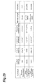
- Fig. 29 is a chart for illustrating comparisons of performances between the second embodiment and other techniques.
- An example of the other techniques to be compared in Fig. 29 in the case of GaAs quasi-phase matching is the technique described in the following Reference Literature 2.
- An example in the case of GaP quasi-phase matching is the technique described in the following Reference Literature 3.
- Examples of the following Reference Literatures 2 and 3 illustrate those yielding the highest conversion efficiency in recent literatures.
- Reference Literature 2 Joseph E. Schaar, et al. "Terahertz Sources Basedon Intracavity Parametric Down-conversion in Quasi-Phase-Matched Garllium Arsenide," IEEE Jounal Topics In Quantum Electronics, vol. 14, No.
- the second embodiment is certainly inferior in terms of conversion efficiency and output intensity.
- the conversion efficiency and output intensity are concerned with pulse responses in the techniques of Reference Literatures 2 and 3 and a continuous light source in the second embodiment. Since the conversion efficiency tends to be higher in pulse responses than in continuous light sources in general, the conversion efficiency and output intensity in the second embodiment cannot simply be considered inferior to those in the techniques of Reference Literatures 2 and 3. It should also be noted that the techniques of Reference Literatures 2 and 3 cannot calculate the conversion efficiency and output intensity in continuous light sources. By contrast, the second embodiment can calculate the conversion efficiency and output intensity for continuous light sources which are needed more in the market.
- the cascade laser Since there are only a small number of literatures for continuous light sources at present, a comparison with a continuous cascade laser must be made if a comparison with a continuous light source is necessary. As illustrated in the following Reference Literature 4, however, the cascade laser has an output intensity of about 300 nW at normal temperature and thus cannot be said to make the frequency variable. That is, effects of improving the output intensity and making the frequency variable, which are achieved in the second embodiment, cannot be expected in the cascade laser. As illustrated in the above-mentioned Non Patent Literature 4, the cascade laser is also problematic in that it can output a region of 0.5 to 3 THz, which is considered the most important, with a high intensity only at a low temperature of 10 K, for example.
- Reference Literature 4 Mikhail A. Belkin, et al. "Room temperature terahertz quantum cascade laser source based on intracavity difference-frequency generation," Appl. Phys. Lett. 92, 201101, 2008
- the crystal itself is about 6 mm in each of Reference Literatures 2 and 3, a resonator is attached thereto so as to raise the conversion efficiency, whereby the size of the resonator is taken as the element length.
- the crystal itself is like a resonator, whereby the optical system is expected to become smaller.
- the idea of the present invention is not limited thereto, whereby the present invention is also applicable to generation of light in regions other than terahertz.
- the first and second incident light components may have the respective incidence angles different from each other.
- the incidence angles different from each other can make the s- and p-polarized light components have the respective resonance frequencies different from each other, thereby changing the frequency of output light.
- materials of the resonator structure 12 limit materials of the resonator structure 12 to GaAs and AlAs for convenience of explanation, materials which can lattice-match in order to produce a multilayer structure while having a crystal structure with broken inversion symmetry such as ZnTe-MgTe, MgSe-ZnTe, CdTe-MgTe, InGaP/GaAs, GaAs/InGaAs, GaAs/Ge, and GaAs/AlGaAs, for example, may also be used in general.
- first and second incident light components are s- and p-polarized, respectively, for convenience of explanation, the first and second incident light components may be p- and s-polarized, respectively, for example.
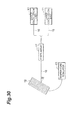
- the optical system illustrated in Fig. 1 may be constructed as an optical system using fibers as illustrated in Fig. 30 .
- This optical system is constructed such as to comprise a polarization-maintaining fiber 16 and a fiber array 17 in place of the mirror 14 and lens 15 in Fig. 1 .
- a product known as TA pro of TOPTICA Photonics AG can be used as laser light sources in the laser oscillation units 10, 11, for instance.
- the generation wavelength region is 1035 to 1085 nm
- generation intensity is 1000 mW
- linewidth is 0.1 to 1 MHz (typical linewidth: 5 ⁇ s).
- one having a generation wavelength region of 1060 to 1083 nm, a generation intensity of 2000 mW, and a linewidth of 0.1 to 1 MHz (typical linewidth: 5 ⁇ s) may also be used.
- a product known as SFL-PM of NovaWave Technologies, Inc. having a generation wavelength region of 1064 nm, a generation intensity of 2000 mW, and a linewidth of less than 100 kHz may also be used.
- polarization-maintaining fiber 16 and fiber array 17 a polarization-maintaining fiber which can simultaneously transmit the p- and s-polarized light components by using a wavelength region of 1060 to 1080 nm may be employed.
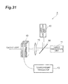
- the optical system illustrated in Fig. 1 can also be constructed as an optical system using a polarization beam splitter as illustrated in Fig. 31 , for example.
- This optical system is constructed such as to comprise a polarization beam splitter 18 in place of the mirror 14 in Fig. 1 .
- the laser oscillation units 10, 11 may employ the same laser light sources used in the above-mentioned optical system with the fibers.
- the polarization beam splitter 18 PBS-HP series of Sigma Koki Co., Ltd. or 05BC15PH.9 of Newport Corporation may be used.
- As the lens 15, any of NYTL and NYDL series of Sigma Koki Co., Ltd. may be used.
- 1...terahertz light generation device 10, 11...laser oscillation unit; 12...resonator structure; 12a...principal surface in the resonator structure 12; 13...temperature regulator; 14... mirror; 15...lens; 16...polarization-maintaining fiber; 17... fiber array; 18...polarization beam splitter; 121... simple resonator; 122, 124... composite photonic crystal structure; 123...simple photonic crystal
- the present invention provides a light generation device and light generation method which can efficiently generate light having a desirable frequency.
Landscapes
- Physics & Mathematics (AREA)
- Nonlinear Science (AREA)
- General Physics & Mathematics (AREA)
- Optics & Photonics (AREA)
- Optical Modulation, Optical Deflection, Nonlinear Optics, Optical Demodulation, Optical Logic Elements (AREA)
Abstract
Description
- The present invention relates to a light generation device and a light generation method.
- As studies on light having a desirable frequency, those of light sources in terahertz regions in particular have actively been under way in recent years. Terahertz waves are considered applicable to various physical property measurements utilizing spectroscopy and imaging techniques employing characteristics of the terahertz waves, and their field of application has been extending over a very wide range of industry, medicine, agriculture, biotechnology, security, and the like. Therefore, much attention has been focused on how to improve techniques for generating the terahertz waves. For example, as methods for generating terahertz waves by using nonlinear optical crystals, various methods such as those utilizing birefringence (see, for example, the following Non Patent Literature 1), quasi-phase matching (see, for example, the following Non Patent Literature 2), double resonator (see, for example, the following Non Patent Literature 3), and parametric oscillation have been proposed.
-
- Non Patent Literature 1: W. Shi and Y. J. Ding, Appl. Phys. Lett. 84, 2004,
- Non Patent Literature 2: K. L. Vodopyanov and M. N. Fejer et al., Appl. Phys. Lett. 89, 14119, 2006
- Non Patent Literature 3: Kitada et al., Appl. Phys. Lett. 95, 111106, 2009
- Non Patent Literature 4: Christoph Walther, et al. "Quantum cascade lasers operating from 1.2 to 1.6 THz, " Appl. Phys. Lett. 91, 131122, 2007
- Non Patent Literature 5: F. Hindle et al., C. R. Physique 9, 262-275, 2008
- However, the conventional techniques exemplified by the above-mentioned
Non Patent Literatures 1 to 3 are not considered realistic as methods for generating light having a desirable frequency, since they mostly use laser light having a high intensity on the order of GW/cm2 as a pumping light source, employ pulsed light which is hard to narrow its linewidth, make a device bulky in principle, or yield a low efficiency in light generation. - As mentioned above, all of the conventional techniques exemplified by the above-mentioned
Non Patent Literatures 1 to 3 use pulsed light for pumping light sources, and none of them is evaluated as a continuous light source. Continuous light is superior to pulsed light in spectral resolution of frequency regions. Therefore, light sources for continuous light are demanded in the market, though those satisfying market demands such as frequency-variable regions, generation intensity, and smaller size are few. While a cascade laser (see, for example, the above-mentioned Non Patent Literature 4) and a photomixing technique (see, for example, the above-mentioned Non Patent Literature 5) have been known as continuous light sources, the former and latter operate at low temperature and yield output on the order of 100 nW or less, respectively, in a THz frequency band, in particular in the range of 0.5 to 3.0 THz required for detecting fingerprint spectra. The latter also lowers its output as the frequency increases, so that the output is 1 nW or less at 2 THz or higher. Though the latter can enhance the generation intensity by increasing the incident light intensity, electrode parts thermally break at a given incident light intensity or higher, which poses an upper limit for improving the output intensity by increasing the incident light intensity. - In view of the above, it is an object of the present invention to provide a light generation device and light generation method which can efficiently generate light having a desirable frequency.
- For achieving the above-mentioned object, the light generation device of the present invention comprises a resonator structure for intensifying incident light and outputting the intensified light and an input unit for inputting the incident light into the resonator structure; wherein the incident light comprises first and second incident light components having polarization states different from each other and frequencies different from each other; wherein the input unit inputs the first and second incident light components at an angle inclined from a direction perpendicular to a principal surface in the resonator structure; and wherein the resonator structure outputs light having a frequency corresponding to a difference between the respective frequencies of the first and second incident light components.
- For achieving the above-mentioned object, the light generation method of the present invention comprises, in a light generation device comprising a resonator structure for intensifying incident light and outputting the intensified light and an input unit for inputting the incident light into the resonator structure, the incident light comprising first and second incident light components having polarization states different from each other and frequencies different from each other, inputting, by the input unit, the first and second incident light components at an angle inclined from a direction perpendicular to a principal surface in the resonator structure and outputting, by the resonator structure, light having a frequency corresponding to a difference between the respective frequencies of the first and second incident light component.
- In thus constructed light generation device and light generation method, the light generation device comprises a resonator structure and an input unit; when the input unit inputs first and second incident light components at an angle with a principal surface in the resonator structure, the resonator structure outputs light having a frequency corresponding to a difference between the respective frequencies of the first and second incident light components as output light. Here, the two incident light components have polarization states different from each other; for example, the first and second incident light components have s- and p-polarized states, respectively. The first and second incident light components may have p- and s-polarized states, respectively. The two incident light components have respective frequencies different from each other; preferably, the s- and p-polarized incident light components have frequencies coinciding with resonance frequencies of s- and p-polarized light components corresponding to the inclination angle of the input unit, respectively. By the resonance frequency is meant herein a frequency which can generate a resonator mode, and is not limited to one frequency value but may be a frequency band having some width which generates the resonator mode. In the foregoing light generation device and light generation method of the present invention, the input unit inputs the incident light with an angle, whereby a shift occurs in the resonance frequency of the resonator structure for differently polarized light components. This is considered to be a phenomenon occurring because of structural birefringence caused by a periodic thin film structure and attributable to the fact that the effective refractive index is changed by polarization. Then, light having a frequency corresponding to the shift is issued as output light. Therefore, light having a desirable frequency to be produced can be generated when the input unit adjusts the incidence angle according to the desirable frequency to be produced. That is, the present invention provides a frequency-variable light generation device and light generation method. The device and method can also improve the efficiency in light generation and reduce the size of the device as a whole.
- The present invention may further comprise a temperature regulation unit for controlling the resonance frequencies of the s- and p-polarized light components by regulating a temperature of the resonator structure.
- In this case, regulating the temperature of the resonator structure can control the resonance frequencies of the s- and p-polarized light components, so that one of the resonance frequencies becomes constant. The temperature regulation is considered to be a relatively easy control technique and thus can improve the convenience of the device structure.
- In the present invention, the resonator structure may be a simple resonator structure comprising a defect layer constituted by a GaAs layer and a reflector constituted by a multilayer comprising GaAs and AlAs layers.
- In the present invention, the resonator structure may be a composite photonic crystal structure comprising a photonic crystal constituted by a multilayer comprising active and inactive layers respectively made of GaAs and AlAs layers and a reflector constituted by a multilayer comprising GaAs and AlAs layers.
- In the present invention, the resonator structure may be a simple photonic crystal structure comprising a photonic crystal constituted by a multilayer comprising active and inactive layers respectively made of GaAs and AlAs layers.
- These represent specific techniques for constructing the resonator structure in the present invention.
- In the present invention, the GaAs and AlAs layers in the reflector in the composite photonic crystal structure may have respective thicknesses different from each other. Here, for example, the effective thickness ratio of the GaAs layer to the AlAs layer = 1:1 in the photonic crystal and 1:4 in the reflector, so that the photonic crystal and reflector may have effective thickness ratios different from each other.
- These can further improve the efficiency in light generation and further reduce the size of the device as a whole.
- In the present invention, the resonator structure may output light having a frequency corresponding to the difference between the respective resonance frequencies of the s- and p-polarized light components having different values as a result of structural birefringence caused by the input unit inputting the first and second incident light components at the inclined angle.
- The present invention can provide a light generation device and light generation method which can efficiently generate light having a desirable frequency.
-
-
Fig. 1 is a schematic structural diagram of a terahertzlight generation device 1; -
Fig. 2 is a diagram imaging howlaser oscillation units resonator structure 12 with first and second incident light components at an angle; -
Fig. 3 is a chart for explaining the fact that a shift occurs in a frequency generating a resonator mode when thelaser oscillation units resonator structure 12 with the first and second incident light components respectively in the s- and p-polarized states at an angle; -
Fig. 4 is a chart for explaining the fact that a shift occurs in the frequency generating a resonator mode when thelaser oscillation units resonator structure 12 with the first and second incident light components respectively in the s- and p-polarized states; -
Fig. 5 is a chart illustrating how a change occurs in the shifted resonance frequency under temperature regulation; -
Fig. 6 is a conceptual diagram of asimple resonator 121 employed as theresonator structure 12 in Structural Example 1; -
Fig. 7 is a flowchart illustrating a procedure of generating output light in a desirable terahertz region by using the terahertzlight generation device 1; -
Fig. 8 is a chart illustrating the relationship between incidence angle θ and frequency of light to be generated in Structural Example 1; -
Fig. 9 is a chart illustrating the relationship between the incidence angle θ and temperature in Structural Example 1; -
Fig. 10 is a chart illustrating the relationship between the incidence angle θ and conversion efficiency in Structural Example 1; -
Fig. 11 is a conceptual diagram of a compositephotonic crystal structure 122 employed as theresonator structure 12 in Structural Example 2; -
Fig. 12 is a chart illustrating the relationship between the incidence angle θ and frequency of light to be generated in Structural Example 2; -
Fig. 13 is a chart illustrating the relationship between the incidence angle θ and temperature in Structural Example 2; -
Fig. 14 is a chart illustrating the relationship between the incidence angle θ and conversion efficiency in Structural Example 2; -
Fig. 15 is a conceptual diagram of asimple photonic crystal 123 employed as theresonator structure 12 in Structural Example 3; -
Fig. 16 is a chart illustrating the relationship between the incidence angle θ and frequency of light to be generated in Structural Example 3; -
Fig. 17 is a chart illustrating the relationship between the incidence angle θ and temperature in Structural Example 3; -
Fig. 18 is a chart illustrating the relationship between the incidence angle θ and conversion efficiency in Structural Example 3; -
Fig. 19 is a conceptual diagram of a compositephotonic crystal structure 124 in a second embodiment; -
Fig. 20 is a set of diagrams for explaining the fact that a frequency difference Δω between respective transmission peaks of p-and s-polarized light components can be changed when the effective thickness ratio between GaAs and AlAs layers is varied; -
Fig. 21 is a set of charts for explaining differences in transmittance spectra between Structural Example 2 of the first embodiment (A) and the second embodiment (B); -
Fig. 22 is a set of charts illustrating operations at low-angle incidence (A) and high-angle incidence (B) in the second embodiment; -
Fig. 23 is a chart illustrating the relationship between the incidence angle θ and frequency of light to be generated in the second embodiment; -
Fig. 24 is a chart illustrating the relationship between the incidence angle θ and temperature in the second embodiment; -
Fig. 25 is a chart illustrating the relationship between the incidence angle θ and conversion efficiency in the second embodiment; -
Fig. 26 is a chart for illustrating the conversion efficiency in Structural Example 2 of the first embodiment and that in the second embodiment in comparison with each other; -
Fig. 27 is a chart for illustrating the full width at half maximum in Structural Example 2 of the first embodiment and that in the second embodiment in comparison with each other; -
Fig. 28 is a chart representing the full width at half maximum comparison ofFig. 27 in a log scale; -
Fig. 29 is a chart for illustrating comparisons of performances between the second embodiment and other techniques; -
Fig. 30 is a diagram for explaining the fact that an optical system inFig. 1 can be constructed as an optical system using fibers; and -
Fig. 31 is a diagram for explaining the fact that the optical system inFig. 1 can be constructed as an optical system using a polarization beam splitter. - In the following, preferred embodiments of the light generation device and light generation method in accordance with the present invention will be explained in detail with reference to the accompanying drawings. In the explanation of the drawings, the same constituents will be referred to with the same signs while omitting their overlapping descriptions.
- To begin with, the structure of the terahertz light generation device 1 (corresponding to the "light generation device" in claims) in accordance with the first embodiment of the present invention will be explained with reference to
Fig. 1. Fig. 1 is a schematic structural diagram of the terahertzlight generation device 1. As illustrated inFig. 1 , the terahertzlight generation device 1 mainly compriseslaser oscillation units 10, 11 (corresponding to the "input unit" in claims), aresonator structure 12, and a temperature regulator 13 (corresponding to the "temperature regulation unit" in the claims). Thelaser oscillation units resonator structure 12 with incident light through amirror 14 and alens 15. Theresonator structure 12 intensifies the incident light fed from thelaser oscillation units - The light incident on the
resonator structure 12 from thelaser oscillation units resonator structure 12 by thelaser oscillation units - The
laser oscillation units resonator structure 12 with the first and second incident light components at an angle inclined from a direction perpendicular to a principal surface in theresonator structure 12.Fig. 2 images how thelaser oscillation units resonator structure 12 with the first and second incident light components at an angle. Thelaser oscillation units resonator structure 12 with the first and second incident light components in a direction D2 which is inclined by an angle θ from a direction D1 which is perpendicular to aprincipal surface 12a in theresonator structure 12. In the first embodiment, thelaser oscillation units - When the
laser oscillation units resonator structure 12 with the first and second incident light components respectively in the s- and p-polarized states at an angle, a shift occurs in a frequency which generates a resonator mode (hereinafter also referred to as "resonance frequency", the resonance frequency is not limited to one frequency value but may be a frequency band having some width which generates the resonator mode).Figs. 3 and4 image this as transmittance vs. wavelength. InFig. 3 , graphs G1 and G2 represent respective cases where thelaser oscillation units resonator structure 12 with the first and second incident light components respectively in the s- and p-polarized states perpendicular to theprincipal surface 12a therein. The resonance frequency in the graph G1 of the s-polarized first incident light component is a frequency corresponding to a wavelength H1 (e.g., 1064 nm), while the resonance frequency in the graph G2 of the p-polarized second incident light component is a frequency corresponding to a wavelength H2 (e.g., 1064 nm). InFig. 4 , graphs G3 and G4 represent respective cases where thelaser oscillation units resonator structure 12 with the first and second incident light components respectively in the s- and p-polarized states at an angle of 15° with theprincipal surface 12a therein. The resonance frequency in the graph G3 of the s-polarized first incident light component is a frequency corresponding to a wavelength H3, while the resonance frequency in the graph G4 of the p-polarized second incident light component is a frequency corresponding to a wavelength H4. In the perpendicular incidence, no shift in resonance frequency occurs between the s- and p-polarized light components as illustrated inFig. 3 . That is, the wavelengths H1 and H2 coincide with each other. Hence,Fig. 3 represents the graphs G1 and G2 superimposed on each other. In the oblique incidence at 15°, on the other hand, a shift occurs in resonance frequency, which is represented by Z1 inFig. 4. Fig. 4 illustrates that the graph G3 has shifted from the graph G1, thereby moving the wavelength of resonance frequency from the wavelength H1 to the wavelength H3 and that the graph G4 has shifted from the graph G2, thereby moving the wavelength of resonance frequency from the wavelength H2 to the wavelength H4.Figs. 3 and4 are respective cases where the incidence angle θ is 0° and 15° while employing asimple photonic crystal 123 as theresonator structure 12 in Structural Example 3 which will be explained later. As will be explained in the following, the output light of the terahertzlight generation device 1 in the first embodiment has a frequency corresponding to the shift Z1 illustrated inFig. 4 unless temperature regulation which will be described later is performed. - The two incident light components fed to the
resonator structure 12 by thelaser oscillation units laser oscillation unit 10, while the frequency of the p-polarized second incident light component coincides with the resonance frequency of p-polarized light corresponding to the inclination angle θ of thelaser oscillation unit 11. Specifically, in the oblique incidence at 15° in the example ofFig. 4 , the transmittance for s-polarized light reaches its peak at the wavelength H3, whereby the s-polarized first incident light component has a frequency corresponding to the wavelength H3. The transmittance for p-polarized light reaches its peak at the wavelength H4, whereby the p-polarized second incident light component has a frequency corresponding to the wavelength H4. In the oblique incidence at 15° in Structural Examples 1 to 3 which will be explained later, the wavelength H4 was 1060.85 nm in the simple resonator of Structural Example 1, 1060.4 nm in the composite photonic crystal of Structural Example 2, and 1060.15 nm in the simple photonic crystal of Structural Example 3. In practice, however, temperature regulation which will be explained later is performed for the convenience of the device design so that the s-polarized first incident light component and p-polarized second incident light component have frequencies corresponding to the wavelengths H5 and H6 (e.g., 1064 nm) illustrated inFig. 5 , respectively.Fig. 5 is a chart illustrating how a change occurs in the resonance frequency under temperature regulation in the situation ofFig. 4 . Letting v1 (the frequency corresponding to the wavelength H5) be the frequency of the s-polarized first incident light component, and v2 (the frequency corresponding to the wavelength H6) be the frequency of the p-polarized second incident light component, the frequency of output light is their difference |v1-v2|. - The
temperature regulator 13 will now be explained in detail. When the incidence angle θ is made greater, the frequency of the resonator mode shifts to the high frequency side. The above-mentionedFigs. 3 and4 represent this fact. Therefore, in order to return the shifted resonance frequency to the original resonance frequency, thetemperature regulator 13 performs temperature regulation for theresonator structure 12, so as to control its refractive index. This controls the respective resonance frequencies of the s- and p-polarized first and second incident light components so that one of the resonance frequencies becomes constant. In the first embodiment, the resonance frequency of the p-polarized second incident light component is controlled so as to return to the resonance frequency in the state where the incidence angle is zero (in the perpendicular incidence state) and become constant.Fig. 5 images this with arrows, so that the resonance frequency of the s-polarized first incident light component changes from the wavelength H3 to the wavelength H5 after the temperature regulation. The temperature regulation also changes the resonance frequency of the p-polarized second incident light component (the frequency corresponding to the wavelength H4) to the wavelength H6. Here, the wavelength H6 is a wavelength coinciding with or near the resonance frequency at the time of perpendicular incidence (frequencies corresponding to the wavelengths H1 and H2; seeFigs. 3 and4 ). After such temperature regulation, the difference in frequency corresponding to the difference in wavelength represented by Z2 inFig. 5 becomes the frequency of the output light of the terahertzlight generation device 1 in the first embodiment. When no temperature regulation is performed, the difference in frequency corresponding to the difference in wavelength represented by Z1 inFigs. 4 and5 becomes the frequency of the output light of the terahertzlight generation device 1 in the first embodiment as mentioned above. - The range of temperature regulation at this time is 220 K to 390 K, for example. The range of temperature regulation varies depending on the resonator structure in use, i.e., the number of films, film thicknesses, and materials in the resonator structure. The following expressions (1) and (2) illustrate temperature dependences of refractive index. The expression (1) illustrates the temperature dependence of refractive index at a part constituted by GaAs in the case where the
resonator structure 12 includes the part constituted by GaAs. The expression (2) illustrates the temperature dependence of refractive index at a part consituted by AlAs in the case where theresonator structure 12 includes the part constituted by AlAs. In the expressions (1) and (2), n and T indicate the refractive index and the temperature of theresonator structure 12, respectively. [Math. 1]

- The following
Reference Literature 1 is one concerning a technique for performing frequency control under temperature regulation.
Reference Literature 1: J. Talghader and J. S. Smith, Appl. Phys. Lett. 66, 335, 1995 - Returning to
Fig. 1 , theresonator structure 12 inputs thereto the s-polarized first incident light component having the frequency v1 as signal light and the p-polarized second incident light component having the frequency v2 as pumping light from thelaser oscillation units laser oscillation units resonator structure 12 with the s-polarized first incident light component as signal light and the p-polarized second incident light component as pumping light at the inclined angle θ, so as to cause structural birefringence, whereby theresonator structure 12 outputs light having a frequency corresponding to the difference between the respective resonance frequencies of the sand p-polarized light components resultantly having different values. In the first embodiment, theresonator structure 12 outputs light in a terahertz region as idler light according to the following Structural Examples 1 to 3. - The structural examples of the terahertz
light generation device 1 in the first embodiment utilizing a plurality of kinds ofresonator structure 12 will now be explained. - The first structural example relates to a case employing a simple resonator as the
resonator structure 12.Fig. 6 is a conceptual diagram of thesimple resonator 121 in this case. As illustrated inFig. 6 , thesimple resonator 121 has a structure comprising a defect layer constituted by a GaAs layer and a reflector (DBR: Distributed Bragg Reflector) constituted by a multilayer composed of GaAs and AlAs layers. - Parameters in the
simple resonator 121 are listed in the following. - 1. GaAs layers in the DBR
Film thickness: 99.09 nm
Number of layers: 17
Refractive index: 3.588 (wavelength: 1064 nm) - 2. AlAs layers in the DBR
Film thickness: 65.73 nm
Number of layers: 17
Refractive index: 2.989 (wavelength: 1064 nm) - 3. GaAs layers in the defect layer
Film thickness: 2391.7 nm
Number of layers: 1
Refractive index: 3.588 (wavelength: 1064 nm) - 4. Number of periods in the DBR: : 17 each in the front and rear, 34 periods in total
- 5. Total crystal length: 7995.24 nm
- The flowchart of
Fig. 7 illustrates a procedure of generating output light in a desirable terahertz region by using the terahertzlight generation device 1 equipped with thus constructedsimple resonator 121. First, a wavelength of a terahertz wave to be generated is determined according to its use (step S1). Subsequently, the kind ofresonator structure 12 is determined (step S2). Thesimple resonator 121 is assumed to be chosen in this structural example. - Next, the incidence angle θ of the s-polarized first incident light component (signal light) and p-polarized second incident light component (pumping light) is determined according to the frequency of the terahertz wave to be generated (step S3). The incidence angle θ is determined by the frequency of light to be generated;
Fig. 8 illustrates the relationship between the incidence angle θ and the frequency of light to be generated when thesimple resonator 121 is chosen as theresonator structure 12. When light at 0.31 THz is to be generated, for example, the incidence angle θ can be set to 65° as illustrated inFig. 8 . - Returning to
Fig. 7 , as the next process, the frequency and intensity of pumping light, the frequency and intensity of signal light, and the temperature of thesimple resonator 121 are determined (step S4). When light at 0.31 THz is to be generated as mentioned above, for example, the frequency of pumping light is kept constant at about 281.95 THz (wavelength: 1064 nm), and its intensity is set to 1 MW/cm2. The intensity is desirably as high as possible in view of conversion efficiency. The frequency of signal light can be determined by 281.95 THz - the difference frequency (the frequency of light to be generated) and thus is set to about 281.64 THz. The intensity of signal light is on a par with or lower than the intensity of pumping light. When the incidence angle θ is set to 65° in order to generate light at 0.31 THz, for example, the temperature of thesimple resonator 121 can be set to 340 K as an absolute temperature as illustrated inFig. 9 . The frequency of pumping light is kept constant at about 281.95 THz (wavelength: 1064 nm) as mentioned above under temperature regulation. - The foregoing generates desirable light at 0.31 THz.
Fig. 10 illustrates the conversion efficiency at this time. As illustrated inFig. 10 , when the incidence angle θ is 65° while thesimple resonator 121 is under temperature regulation at 340 K, the conversion efficiency is 2.1e-006%. In view of results in other frequency ranges, the conversion efficiency rises as the incidence angle θ is made greater, so that the maximum value of conversion efficiency appears in the vicinity of 65°. ThoughFig. 10 represents 2.1e-006% as the maximum conversion efficiency since the confinement effect is weakened in view of performances of readily usable laser light sources at present, a higher conversion efficiency value can be obtained by changing conditions. - Examples of merits in this structural example include: 1. thinness in the device; 2. variable generation frequency; and 3. achievability of a high-output continuous light source. The device, i.e., the
resonator structure 12, is thinner by three digits than those conventionally known. Additionally taking account of the fact that the conversion efficiency increases in proportion to the square of the thickness, the device of this structural example can be considered to be one having performances beyond comparison. The device ofNon Patent Literature 3, whose structure is totally different from that of this structural example and cannot be compared therewith, seems to be on the same order as with this structural example only in terms of the thickness of the resonator structure. The same literature has not yet reached discussions of conversion efficiency, so that its conversion efficiency cannot be compared with that in the device of this structural example. However, according to the knowledge of the inventors, this structural example seems to be superior to the literature beyond comparison in terms of conversion efficiency when their conditions such as incident light intensity and element thickness are made equivalent to each other. - The fact that the generation frequency and incident light frequency are variable acts very advantageously for applying terahertz waves. This is a capability not found in any of the quasi-phase matching of
Non Patent Literature 2 and the double resonator ofNon Patent Literature 3, whereby this structural example can be considered a device more suitable for applications than are the techniques of both literatures. - Since the conversion efficiency is proportional to the incident light intensity, pulsed light having a peak-to-peak value higher than that of continuous light yields a higher conversion efficiency value. Therefore, various studies (e.g., the above-mentioned
Non Patent Literatures 1 to 3) calculate the conversion efficiency in pulsed light, while the frequency resolution of pulsed light is inferior to that of continuous light and thus has low accuracy when obtaining an absorption spectrum, for example. There are only a very limited number of literatures having tried terahertz generations of continuous light, which compels this specification to perform a comparison with pulsed light. The value of conversion efficiency itself in the first embodiment is inevitably inferior to that in pulsed light. - While the output in photomixing (e.g., the above-mentioned Non Patent Literature 5) decreases in the unit of digits as the frequency becomes higher, the output in the first embodiment does not decrease so much even in the frequency region of 0.5 to 3.0 THz. The linewidth of thus generated terahertz light seems to be on substantially the same order as that of the pumping light or signal light. Though the structural example in the first embodiment assumes a linewidth on the order of GHz, continuous light sources on the order of kHz and MHz are commercially available at present, whereby designs conforming thereto are expected to further raise the conversion efficiency. When fed with light having a linewidth on the order of GHz or less, even the current structural example can generate light having the same order of linewidth. The value of conversion efficiency may become higher than the above-mentioned value depending on structural differences in the resonator structure 12 (differences in the structure itself as will be illustrated by the following Structural Examples 2 and 3 and differences in the growth face).
- The next structural example relates to a case employing a composite
photonic crystal structure 122 as theresonator structure 12.Fig. 11 is a conceptual diagram of the compositephotonic crystal structure 122 in this case. As illustrated inFig. 11 , the compositephotonic crystal structure 122 has a structure comprising a photonic crystal constituted by a multilayer composed of active and inactive layers respectively made of GaAs and AlAs layers and a reflector (DBR) constituted by a multilayer of GaAs and AlAs layers. - Parameters in the composite
photonic crystal structure 122 are listed in the following. - 1. GaAs layers in the DBR
Film thickness: 79.18 nm
Number of layers: 14
Refractive index: 3.382 (wavelength: 1064 nm; temperature: 200 K) - 2. AlAs layers in the DBR
Film thickness: 92.49 nm
Number of layers: 14
Refractive index: 2.895 (wavelength: 1064 nm; temperature: 200 K) - 3. GaAs layers in the photonic crystal
Film thickness: 72.53 nm
Number of layers: 13
Refractive index: 3.382 (wavelength: 1064 nm; temperature: 200 K) - 4. AlAs layers in the photonic crystal
Film thickness: 84.72 nm
Number of layers: 12
Refractive index: 2.895 (wavelength: 1064 nm; temperature: 200 K) - 5. Number of periods in the DBR: 14 each in the front and rear, 28 periods in total
- 6. Total crystal length: 6766.01 nm
- The procedure of generating output light in a desirable terahertz region by using the terahertz
light generation device 1 equipped with thus constructed compositephotonic crystal structure 122 is as illustrated in the flowchart ofFig. 7 . First, a wavelength of a terahertz wave to be generated is determined according to its use (step S1). Subsequently, the kind ofresonator structure 12 is determined (step S2). The compositephotonic crystal structure 122 is assumed to be chosen in this structural example. - Next, the incidence angle θ of the s-polarized first incident light component (signal light) and p-polarized second incident light component (pumping light) is determined according to the frequency of the terahertz wave to be generated (step S3). The incidence angle θ is determined by the frequency of light to be generated;
Fig. 12 illustrates the relationship between the incidence angle θ and the frequency of light to be generated when the compositephotonic crystal structure 122 is chosen as theresonator structure 12. When light at 1.55 THz is to be generated, for example, the incidence angle θ can be set to 67° as illustrated inFig. 12 . - Returning to
Fig. 7 , as the next process, the frequency and intensity of pumping light, the frequency and intensity of signal light, and the temperature of the compositephotonic crystal structure 122 are determined (step S4). When light at 1.55 THz is to be generated as mentioned above, for example, the frequency of pumping light is kept constant at about 281.95 THz (wavelength: 1064 nm), and its intensity is set to 1 MW/cm2. The intensity is desirably as high as possible in view of conversion efficiency. The frequency of signal light can be determined by 281.95 THz - the difference frequency (the frequency of light to be generated) and thus is set to about 280.4 THz. The intensity of signal light is on a par with or lower than the intensity of pumping light. When the incidence angle θ is set to 67° in order to generate light at 1.55 THz, for example, the temperature of the compositephotonic crystal structure 122 can be set to 380 K as an absolute temperature as illustrated inFig. 13 . The frequency of pumping light is kept constant at about 281.95 THz (wavelength: 1064 nm) as mentioned above under temperature regulation. - The foregoing generates desirable light at 1.55 THz.
Fig. 14 illustrates the conversion efficiency at this time. As illustrated inFig. 14 , when the incidence angle θ is 67° while the compositephotonic crystal structure 122 is under temperature regulation at 380 K, the conversion efficiency is 6e-005%. In view of results in other frequency ranges, the conversion efficiency rises as the incidence angle θ is made greater, so that the maximum value of conversion efficiency appears in the vicinity of 67°. ThoughFig. 14 represents 6e-005% as the maximum conversion efficiency since the confinement effect is weakened in view of performances of readily usable laser light sources at present, a higher conversion efficiency value can be obtained by changing conditions. Superior points of this structural example, which are the same as those mentioned in Structural Example 1, will not be described. - The next structural example relates to a case employing the
simple photonic crystal 123 as theresonator structure 12.Fig. 15 is a conceptual diagram of the compositephotonic crystal structure 123 in this case. As illustrated inFig. 15 , thesimple photonic crystal 123 has a structure comprising a photonic crystal constituted by a multilayer composed of active and inactive layers respectively made of GaAs and AlAs layers. - Parameters in the
simple photonic crystal 123 are listed in the following. - 1. GaAs layers in the photonic crystal
Film thickness: 74.74 nm
Number of layers: 70
Refractive index: 3.588 (wavelength: 1064 nm) - 2. AlAs layers in the photonic crystal
Film thickness: 87.31 nm
Number of layers: 69
Refractive index: 2.989 (wavelength: 1064 nm) - 3. Total crystal length: 11256.19 nm
- The procedure of generating output light in a desirable terahertz region by using the terahertz
light generation device 1 equipped with thus constructed simplephotonic crystal 123 is as illustrated in the flowchart ofFig. 7 . First, a wavelength of a terahertz wave to be generated is determined according to its use (step S1). Subsequently, the kind ofresonator structure 12 is determined (step S2). Thesimple photonic crystal 123 is assumed to be chosen in this structural example. - Next, the incidence angle θ of the s-polarized first incident light component (signal light) and p-polarized second incident light component (pumping light) is determined according to the frequency of the terahertz wave to be generated (step S3). The incidence angle θ is determined by the frequency of light to be generated;
Fig. 16 illustrates the relationship between the incidence angle θ and the frequency of light to be generated when thesimple photonic crystal 123 is chosen as theresonator structure 12. When light at 3 THz is to be generated, for example, the incidence angle θ can be set to 85° as illustrated inFig. 16 . - Returning to
Fig. 7 , as the next process, the frequency and intensity of pumping light, the frequency and intensity of signal light, and the temperature of thesimple photonic crystal 123 are determined (step S4). When light at 3 THz is to be generated as mentioned above, for example, the frequency of pumping light is kept constant at about 281.95 THz (wavelength: 1064 nm), and its intensity is set to 1 MW/cm2. The intensity is desirably as high as possible in view of conversion efficiency. The frequency of signal light can be determined by 281.95 THz - the difference frequency (the frequency of light to be generated) and thus is set to about 278.95 THz. The intensity of signal light is on a par with or lower than the intensity of pumping light. When the incidence angle θ is set to 85° in order to generate light at 3 THz, for example, the temperature of thesimple photonic crystal 123 can be set to 420 K as an absolute temperature as illustrated inFig. 17 . The frequency of pumping light is kept constant at about 281.95 THz (wavelength: 1064 nm) as mentioned above under temperature regulation. - The foregoing generates desirable light at 3 THz.
Fig. 18 illustrates the conversion efficiency at this time. As illustrated inFig. 18 , when the incidence angle θ is 85° while thesimple photonic crystal 123 is under temperature regulation at 420 K, the conversion efficiency is 3.9e-005%. In view of results in other frequency ranges, the conversion efficiency rises as the incidence angle θ is made greater, so that the maximum value of conversion efficiency appears in the vicinity of 85°. ThoughFig. 18 represents 3.9e-005% as the maximum conversion efficiency since the confinement effect is weakened in view of performances of readily usable laser light sources at present, a higher conversion efficiency value can be obtained by changing conditions. Superior points of this structural example, which are the same as those mentioned in Structural Example 1, will not be described. - Operations and effects of the terahertz
light generation device 1 in accordance with the first embodiment will now be explained. The terahertzlight generation device 1 of the first embodiment generates terahertz waves by using the GaAs/AlAsresonator structure 12. When light is incident on theresonator structure 12 at an angle, its transmittance spectrum shifts as the angle increases, while a difference occurs in the width of shifting frequency between the s- and p-polarized light components (seeFig. 3 ). This is considered to be a phenomenon occurring because of structural birefringence caused by a periodic thin film structure and attributable to the fact that the effective refractive index is changed by polarization. Here, light having two frequencies in conformity to the respective transmittance spectra of the polarized light components incident on the resonator structure can enhance the optical electric field therewithin, thereby causing strong difference frequency generation (DFG). Thus generated difference frequency reaches a terahertz region, and its conversion efficiency is high as mentioned above. In view of the fact that the first embodiment generates continuous light with the incident light intensity on the order of MW/cm2, the conversion efficiency by the first embodiment is considered to be much superior to that in the prior art (in the case where the incident light intensity is on the order of GW/cm2 in particular). Since the difference frequency changes with the incidence angle θ (seeFigs. 8 ,12 , and16 ), the terahertzlight generation device 1 of the first embodiment can be utilized as a frequency-variable terahertz light source. - As can be seen from the fact that the
simple resonator 121, compositephotonic crystal structure 122, and simplephotonic crystal 123 have total crystal lengths of 8.0 µm, 6.9 µm, and 11.26 µm, respectively, theresonator structure 12 in the terahertzlight generation device 1 in the first embodiment has a crystal length of several tens of micrometers at the longest. This can reduce the size of the device as a whole, whereby the terahertzlight generation device 1 of the first embodiment can be employed as a highly versatile terahertz light source. - In the first embodiment, the
laser oscillation units resonator structure 12 with the first and second incident light components at the same angle, while thetemperature regulator 13 performs temperature regulation for theresonator structure 12. This controls the respective resonance frequencies of the s- and p-polarized light components, so that one of the resonance frequencies becomes constant. The temperature regulation is considered to be a relatively easy control technique and thus can improve the convenience of the device structure. - The second embodiment of the present invention will now be explained. The second embodiment has a lot in common with Structural Example 2 of the first embodiment but differs therefrom in thickness of the GaAs and AlAs layers in the reflector. More specifically, the effective thickness ratio of GaAs layer to AlAs layer in the reflector = 1:4 in the second embodiment. By contrast, the effective thickness ratio of GaAs layer to AlAs layer in the reflector = 1:1 in Structural Example 2 of the first embodiment. In the following, differences between the second embodiment and Structural Example 2 of the first embodiment will mainly be explained while omitting their common features as much as possible.
- The effective thickness ratio of GaAs layer to AlAs layer in Structural Example 2 of the first embodiment is as follows. Here, the effective thickness is a value obtained by multiplying film thickness by refractive index.
- 1. In the DBR part
The effective thickness of GaAs layer = 79.18 × 3.382 = 267.8
The effective thickness of AlAs layer = 92.49 × 2.895 = 267.8
The effective thickness ratio of GaAs layer to AlAs layer = 267.8:267.8 = 1:1 - 2. In the photonic crystal part
The effective thickness of GaAs layer = 72.53 × 3.382 = 245.3
The effective thickness of AlAs layer = 84.72 × 2.895 = 245.3
The effective thickness ratio of GaAs layer to AlAs layer = 245.3:245.3 = 1:1 - On the other hand, the second embodiment employs a composite photonic crystal structure as the
resonator structure 12 ofFig. 1 as with Structural Example 2 of the first embodiment but differs therefrom in film thickness in the DBR part.Fig. 19 is a conceptual diagram of the compositephotonic crystal structure 124 in the second embodiment. As illustrated inFig. 19 , the compositephotonic crystal structure 124 has a structure comprising a photonic crystal constituted by a multilayer composed of active and inactive layers respectively made of GaAs and AlAs layers and a reflector (DBR) constituted by a multilayer of GaAs and AlAs layers. - Parameters in the composite
photonic crystal structure 124 are listed in the following. - 1. GaAs layers in the DBR
Film thickness: 31.00 nm
Number of layers: 30
Refractive index: 3.382 (wavelength: 1064 nm; temperature: 200 K) - 2. AlAs layers in the DBR
Film thickness: 145.00 nm
Number of layers: 30
Refractive index: 2.895 (wavelength: 1064 nm; temperature: 200 K) - 3. GaAs layers in the photonic crystal
Film thickness: 74.50 nm
Number of layers: 45
Refractive index: 3.382 (wavelength: 1064 nm; temperature: 200 K) - 4. AlAs layers in the photonic crystal
Film thickness: 87.00 nm
Number of layers: 44
Refractive index: 2.895 (wavelength: 1064 nm; temperature: 200 K) - 5. Number of periods in the DBR: 30 each in the front and rear, 60 periods in total
- 6. Total crystal length: 17740.5 nm
- Hence, the effective thickness ratio of GaAs layer to AlAs layer in the second embodiment is as follows:
- 1. In the DBR part
The effective thickness of GaAs layer = 31.00 × 3.382 = 104.8
The effective thickness of AlAs layer = 145.00 × 2.895 = 419.8
The effective thickness ratio of GaAs layer to AlAs layer = 104.8:419.8 = 1:4 - 2. In the photonic crystal part
The effective thickness of GaAs layer = 74.50 × 3.382 = 252.0
The effective thickness of AlAs layer = 87.00 × 2.895 = 251.9
The effective thickness ratio of GaAs layer to AlAs layer = 252.0:251.9 = 1:1 - In the second embodiment, as illustrated in the foregoing, the respective effective thicknesses of GaAs and AlAs layers coincide with each other in the photonic crystal part, but differ from each other and yield a ratio of 1:4 in the DBR part.
- Making the GaAs and AlAs layers have respective effective thicknesses different from each other, i.e., varying the effective thickness ratio between the GaAs and AlAs layers, can change the frequency difference Δω between the respective transmission peaks of the p- and s-polarized light components (corresponding to Z1 and Z2 in
Figs. 4 and5 ).Fig. 20 illustrates this fact; inFig. 20(A) , X in the abscissa and the ordinate indicate the effective thickness ratio and Δω, respectively. Here, X is a value represented by the following expression:
- As illustrated in
Fig. 20(A) , a large value (1.07 THz) of difference frequency is obtained in the case where X = 0.5 at which the effective thickness ratio is 1:1 (the case ofFig. 20(B) , i.e., Structural Example 2 of the first embodiment), while a small value (0.3 THz) of difference frequency is obtained in the case where X = 0.8 at which the effective thickness ratio is 1:4 (the case ofFig. 20(C) , i.e., the second embodiment). InFigs. 20(B) and 20(C) , graphs G7 and G9 indicate transmission spectra of the s-polarized light component, while graphs G8 and G10 indicate transmission spectra of the p-polarized light component. Though X inFig. 20 indicates the effective thickness ratio, the thickness ratio not multiplied by the refractive index exhibits a similar behavior of Δω, whereby the effective thickness ratio will simply be referred to as thickness ratio in the following explanation. -
Fig. 21 is a set of charts for explaining differences in transmittance spectra between Structural Example 2 of the first embodiment and the second embodiment.Fig. 21(A) illustrates the case of Structural Example 2 of the first embodiment, whileFig. 21(B) illustrates the case of the second embodiment. Each of them constructs the photonic crystal (PC) at the thickness ratio of 1:1 and uses the largest Δω. As for the DBR, however, Structural Example 2 of the first embodiment inFig. 21 (A) uses a thickness ratio of 1:1, while the second embodiment inFig. 21 (B) uses a thickness ratio of 1:4, for example, such that one is thicker than the other. InFig. 21 , graphs G11, G13, G15, G17, G19, and G21 illustrate transmission spectra of the s-polarized light component, while graphs G12, G14, G16, G18, G20, and G22 illustrate transmission spectra of the p-polarized light component. - In the case of Structural Example 2 of the first embodiment illustrated in
Fig. 21 (A) , the DBR exhibits high reflectance at a PC peak wavelength ω1 of the p-polarized light component (the PC peak wavelength ω1 of the p-polarized light component corresponds to the center part of a depression of the graph G14, i.e., the center part of the photonic bandgap) and at a PC peak wavelength ω2 of the s-polarized light component (the PC peak wavelength ω2 of the s-polarized light component corresponds to the center part of a depression of the graph G13, i.e., the center part of the photonic bandgap) and thus has about the same reflectance for both the p- and s-polarized light components. In the case of the second embodiment illustrated inFig. 21(B) , on the other hand, the DBR exhibits high reflectance at a PC peak wavelength ω3 of the p-polarized light component (the PC peak wavelength ω3 of the p-polarized light component corresponds to the center part of a depression of the graph G20, i.e., the center part of the photonic bandgap) and low reflectance at a PC peak wavelength ω4 of the s-polarized light component (the PC peak wavelength ω4 of the s-polarized light component does not correspond to the center part of a depression of the graph G19, i.e., the center part of the photonic bandgap) and thus has a high confinement effect only for the p-polarized light component. As a result, when a composite photonic crystal is employed, Structural Example 2 of the first embodiment inFig. 21(A) yields a large difference |h1 - h2| between the respective full widths at half maximum h1, h2 of the p- and s-polarized light components as illustrated in the lowermost stage ofFig. 21(A) , while the second embodiment inFig. 21(B) yields a small difference |h3 - h4| between the respective full widths at half maximum h3, h4 of the p- and s-polarized light components as illustrated in the lowermost stage ofFig. 21(A) . The full width at half maximum (FWHM) is a value indicating a difference in wavelength (frequency) which is 0.5 times the peak value of a transmission peak. -
Fig. 22 is a set of charts illustrating operations at low-angle incidence and high-angle incidence in the second embodiment.Figs. 22(A) and 22(B) illustrate the respective cases of low-angle incidence and high-angle incidence. In the low-angle incidence ofFig. 22(A) , the PC peak wavelengths (ω5, ω6) of p- and s-polarized light components are located in a high reflection part of the DBR, whereby the DBR exhibits high reflectance for both of them. In the high-angle incidence ofFig. 22(B) , on the other hand, the DBR exhibits high reflectance at the PC peak wavelength ω7 of the p-polarized light component and low reflectance at the PC peak wavelength ω8 of the s-polarized light component. While Structural Example 2 of the first embodiment may enhance and reduce confinement effects for the p- and s-polarized light components, respectively, as the angle increases, so that only the s-polarized light component can be utilized well, the second embodiment adjusts the thickness ratio between the GaAs and AlAs layers and thus can keep an appropriate full width at half maximum, thereby making it possible to keep the best full width at half maximum either at low or high angle. InFig. 22 , graphs G23, G25, G27, G29, G31, and G33 illustrate transmission spectra of the s-polarized light component, while graphs G24, G26, G28, G30, G32, and G34 illustrate transmission spectra of the p-polarized light component. - The procedure of generating output light in a desirable terahertz region by using the terahertz
light generation device 1 equipped with thus constructed compositephotonic crystal structure 124 is as illustrated in the flowchart ofFig. 7 . First, a wavelength of a terahertz wave to be generated is determined according to its use (step S1). Subsequently, the kind ofresonator structure 12 is determined (step S2). The compositephotonic crystal structure 124 is assumed to be chosen in this structural example. - Next, the incidence angle θ of the s-polarized first incident light component (signal light) and p-polarized second incident light component (pumping light) is determined according to the frequency of the terahertz wave to be generated (step S3). The incidence angle θ is determined by the frequency of light to be generated;
Fig. 23 illustrates the relationship between the incidence angle θ and the frequency of light to be generated when the compositephotonic crystal structure 124 is chosen as the resonator structure. When light at 1.2 THz is to be generated, for example, the incidence angle θ can be set to 40° as illustrated inFig. 23 . In the second embodiment, as the incidence angle increases, the difference (Δω) between the respective transmittance spectra of the p- and s-polarized light components becomes greater, thereby making the generation frequency higher. - Returning to
Fig. 7 , as the next process, the frequency and intensity of pumping light, the frequency and intensity of signal light, and the temperature of the compositephotonic crystal structure 124 are determined (step S4). When light at 1.2 THz is to be generated as mentioned above, for example, the frequency of pumping light is kept constant at about 281.95 THz (wavelength: 1064 nm), and its intensity is set to 1 MW/cm2. The intensity is desirably as high as possible in view of conversion efficiency. The frequency of signal light can be determined by 281.95 THz - the difference frequency (the frequency of light to be generated) and thus is set to about 280.85 THz. The intensity of signal light is on a par with or lower than the intensity of pumping light. When the incidence angle θ is set to 40° in order to generate light at 1.2 THz, for example, the temperature of the compositephotonic crystal structure 124 can be set to 290 K as an absolute temperature as illustrated inFig. 24 . The frequency of pumping light is kept constant at about 281.95 THz (wavelength: 1064 nm) as mentioned above under temperature regulation. In the second embodiment, as the incidence angle increases, the shift in transmittance spectra becomes greater, thereby making it necessary to change the sample temperature correspondingly. - The foregoing generates desirable light at 1.2 THz.
Fig. 25 illustrates the conversion efficiency at this time. As illustrated inFig. 25 , when the incidence angle θ is 40° while the compositephotonic crystal structure 122 is under temperature regulation at 290 K, the conversion efficiency is 1.8e-003%. It is seen to achieve an improvement in conversion efficiency by two digits or more when compared with the results of Structural Example 2 of the first embodiment illustrated inFig. 14 .Fig. 26 is a chart for illustrating the conversion efficiency in Structural Example 2 of the first embodiment and that in the second embodiment in comparison with each other. Graphs G35 and G36 illustrate the respective conversion efficiencies in Structural Example 2 of the first embodiment and the second embodiment. The conversion efficiency in the second embodiment is seen to be higher than that in Structural Example 2 of the first embodiment at all the incidence angles. For convenience in representation,Fig. 26 indicates the conversion efficiency in a log scale. -
Fig. 27 is a chart for illustrating the full width at half maximum in Structural Example 2 of the first embodiment and that in the second embodiment in comparison with each other. Graphs G37 and G38 illustrate the respective full widths at half maximum of the p-and s-polarized light components in Structural Example 2 of the first embodiment, while graphs G39 and G40 illustrate the respective full widths at half maximum of the p- and s-polarized light components in the second embodiment. In the second embodiment illustrated by the graphs G39 and G40, the full width at half maximum in each of the polarized light components is near the ideal full width at half maximum of 0.01 [nm] and only 0.055 [nm] at the maximum. In Structural Example 2 of the first embodiment illustrated by the graphs G37 and G38, on the other hand, the full width at half maximum of the s-polarized light component becomes 0.01 [nm] in the vicinity of an incidence angle of 70°, where the full width at half maximum of the p-polarized light component increases to 0.35 [nm]. -
Fig. 28 is a chart illustrating the full width at half maximum comparison in a log scale for convenience in representation. In conformity toFig. 27 , the same numbers are used in the graphs. In the case of Structural Example 2 in the first embodiment, as illustrated inFig. 28 , the difference in full width at half maximum between the p- and s-polarized light components becomes greater as the incidence angle increases (see graphs G37' and G38'). In the case of the second embodiment, on the other hand, the difference in full width at half maximum between the p- and s-polarized light components is small even when the incidence angle is large (see graphs G39' and G40'). Since the difference in full width at half maximum is thus constant, both of the p- and s-polarized light components can enter the inside of the crystal even at higher angle, thereby contributing to terahertz wave generation. Since the p- and s-polarized light components have small full widths at half maximum, the electric field enhancement effect within the crystal is so high that an increase in conversion efficiency can be expected. -
Fig. 29 is a chart for illustrating comparisons of performances between the second embodiment and other techniques. An example of the other techniques to be compared inFig. 29 in the case of GaAs quasi-phase matching is the technique described in the followingReference Literature 2. An example in the case of GaP quasi-phase matching is the technique described in the followingReference Literature 3. Examples of the followingReference Literatures
Reference Literature 2: Joseph E. Schaar, et al. "Terahertz Sources Basedon Intracavity Parametric Down-conversion in Quasi-Phase-Matched Garllium Arsenide," IEEE Jounal Topics In Quantum Electronics, vol. 14, No. 2, 2008
Reference Literature 3: Eliot B.Petersen, et al. "Efficient parametric terahertz generation in quasi-phase-matched GaP through cavity enhanced difference-frequency genaration," Appl. Phys. Lett. 98, 121119,2011 - When the techniques of
Reference Literatures Reference Literatures Reference Literatures Reference Literatures - Since there are only a small number of literatures for continuous light sources at present, a comparison with a continuous cascade laser must be made if a comparison with a continuous light source is necessary. As illustrated in the following
Reference Literature 4, however, the cascade laser has an output intensity of about 300 nW at normal temperature and thus cannot be said to make the frequency variable. That is, effects of improving the output intensity and making the frequency variable, which are achieved in the second embodiment, cannot be expected in the cascade laser. As illustrated in the above-mentionedNon Patent Literature 4, the cascade laser is also problematic in that it can output a region of 0.5 to 3 THz, which is considered the most important, with a high intensity only at a low temperature of 10 K, for example. By contrast, the second embodiment is not restricted so as to be operable under low temperature and so forth.
Reference Literature 4: Mikhail A. Belkin, et al. "Room temperature terahertz quantum cascade laser source based on intracavity difference-frequency generation," Appl. Phys. Lett. 92, 201101, 2008 - While the crystal itself is about 6 mm in each of
Reference Literatures - Though preferred embodiments of the present invention have been explained in the foregoing, the present invention is not limited to the above-mentioned embodiments as a matter of course.
- For example, while the above-mentioned embodiments generate light in the terahertz region by way of example, the idea of the present invention is not limited thereto, whereby the present invention is also applicable to generation of light in regions other than terahertz.
- While the
laser oscillation units resonator structure 12 with the first and second incident light components at the same angle in the above-mentioned embodiments, the first and second incident light components may have the respective incidence angles different from each other. The incidence angles different from each other can make the s- and p-polarized light components have the respective resonance frequencies different from each other, thereby changing the frequency of output light. - Though the above-mentioned embodiments set forth the
simple resonator 121, compositephotonic crystal structure 122, and simplephotonic crystal 123 as examples of theresonator structure 12, the double resonator described inNon Patent Literature 3, for example, is also a structure to which the system of the present invention is applicable. - Though the above-mentioned embodiments limit materials of the
resonator structure 12 to GaAs and AlAs for convenience of explanation, materials which can lattice-match in order to produce a multilayer structure while having a crystal structure with broken inversion symmetry such as ZnTe-MgTe, MgSe-ZnTe, CdTe-MgTe, InGaP/GaAs, GaAs/InGaAs, GaAs/Ge, and GaAs/AlGaAs, for example, may also be used in general. - Though the above-mentioned embodiments assume that the first and second incident light components are s- and p-polarized, respectively, for convenience of explanation, the first and second incident light components may be p- and s-polarized, respectively, for example.
- The optical system in the embodiments will now be explained in more detail. The following is in common between the first and second embodiments. That is, the optical system illustrated in
Fig. 1 may be constructed as an optical system using fibers as illustrated inFig. 30 . This optical system is constructed such as to comprise a polarization-maintainingfiber 16 and afiber array 17 in place of themirror 14 andlens 15 inFig. 1 . In a device structure example in this case, a product known as TA pro of TOPTICA Photonics AG can be used as laser light sources in thelaser oscillation units fiber 16 andfiber array 17, a polarization-maintaining fiber which can simultaneously transmit the p- and s-polarized light components by using a wavelength region of 1060 to 1080 nm may be employed. - The optical system illustrated in
Fig. 1 can also be constructed as an optical system using a polarization beam splitter as illustrated inFig. 31 , for example. This optical system is constructed such as to comprise apolarization beam splitter 18 in place of themirror 14 inFig. 1 . In a device structure example in this case, thelaser oscillation units polarization beam splitter 18, PBS-HP series of Sigma Koki Co., Ltd. or 05BC15PH.9 of Newport Corporation may be used. As thelens 15, any of NYTL and NYDL series of Sigma Koki Co., Ltd. may be used. - 1...terahertz light generation device; 10, 11...laser oscillation unit; 12...resonator structure; 12a...principal surface in the
resonator structure 12; 13...temperature regulator; 14... mirror; 15...lens; 16...polarization-maintaining fiber; 17... fiber array; 18...polarization beam splitter; 121... simple resonator; 122, 124... composite photonic crystal structure; 123...simple photonic crystal - The present invention provides a light generation device and light generation method which can efficiently generate light having a desirable frequency.
Claims (12)
- A light generation device comprising:a resonator structure for intensifying incident light and outputting the intensified light; andan input unit for inputting the incident light into the resonator structure;wherein the incident light comprises first and second incident light components having polarization states different from each other and frequencies different from each other;wherein the input unit inputs the first and second incident light components at an angle inclined from a direction perpendicular to a principal surface in the resonator structure; andwherein the resonator structure outputs light having a frequency corresponding to a difference between the respective frequencies of the first and second incident light components.
- A light generation device according to claim 1, wherein the first and second incident light components have s- and p-polarized states, respectively, or p- and s-polarized states, respectively.
- A light generation device according to claim 2, wherein the frequency of the s-polarized incident light component is a resonance frequency of the s-polarized light component corresponding to the inclination angle of the input unit; and
wherein the frequency of the p-polarized incident light component is a resonance frequency of the p-polarized light component corresponding to the inclination angle of the input unit. - A light generation device according to claim 3, further comprising a temperature regulation unit for controlling the resonance frequencies of the s- and p-polarized light components by regulating a temperature of the resonator structure.
- A light generation device according to one of claims 1 to 4, wherein the resonator structure is a simple resonator structure comprising a defect layer constituted by a GaAs layer and a reflector constituted by a multilayer comprising GaAs and AlAs layers.
- A light generation device according to one of claims 1 to 4, wherein the resonator structure is a composite photonic crystal structure comprising a photonic crystal constituted by a multilayer comprising active and inactive layers respectively made of GaAs and AlAs layers and a reflector constituted by a multilayer comprising GaAs and AlAs layers.
- A light generation device according to claim 6, wherein the GaAs and AlAs layers in the reflector have respective thicknesses different from each other.
- A light generation device according to claim 7, wherein the effective thickness ratio of the GaAs layer to the AlAs layer = 1:1 in the photonic crystal and 1:4 in the reflector, so that the photonic crystal and reflector have effective thickness ratios different from each other.
- A light generation device according to one of claims 1 to 4, wherein the resonator structure is a simple photonic crystal structure comprising a photonic crystal constituted by a multilayer comprising active and inactive layers respectively made of GaAs and AlAs layers.
- A light generation device according to claim 3, wherein the resonator structure outputs light having a frequency corresponding to the difference between the respective resonance frequencies of the s-and p-polarized light components having different values as a result of structural birefringence caused by the input unit inputting the first and second incident light components at the inclined angle.
- A light generation method in a light generation device comprising a resonator structure for intensifying incident light and outputting the intensified light and an input unit for inputting the incident light into the resonator structure;
the incident light comprising first and second incident light components having polarization states different from each other and frequencies different from each other;
the method comprising:inputting, by the input unit, the first and second incident light components at an angle inclined from a direction perpendicular to a principal surface in the resonator structure; andoutputting, by the resonator structure, light having a frequency corresponding to a difference between the respective frequencies of the first and second incident light component. - A light generation method according to claim 11, wherein the first and second incident light components have s- and p-polarized states, respectively, or p- and s-polarized states, respectively;
wherein the frequency of the s-polarized incident light component is a resonance frequency of the s-polarized light component corresponding to the inclination angle of the input unit;
wherein the frequency of the p-polarized incident light component is a resonance frequency of the p-polarized light component corresponding to the inclination angle of the input unit;
wherein the light generation device further comprises a temperature regulation unit; and
wherein the method further comprises the step of controlling, by the temperature regulation unit, the resonance frequencies of the s- and p-polarized light components by regulating a temperature of the resonator structure.
Applications Claiming Priority (2)
| Application Number | Priority Date | Filing Date | Title |
|---|---|---|---|
| JP2010275013 | 2010-12-09 | ||
| PCT/JP2011/078485 WO2012077769A1 (en) | 2010-12-09 | 2011-12-08 | Light generation device and light generation method |
Publications (2)
| Publication Number | Publication Date |
|---|---|
| EP2650723A1 true EP2650723A1 (en) | 2013-10-16 |
| EP2650723A4 EP2650723A4 (en) | 2016-09-14 |
Family
ID=46207251
Family Applications (1)
| Application Number | Title | Priority Date | Filing Date |
|---|---|---|---|
| EP11846888.3A Withdrawn EP2650723A4 (en) | 2010-12-09 | 2011-12-08 | LIGHT GENERATING DEVICE AND LIGHT GENERATING METHOD |
Country Status (5)
| Country | Link |
|---|---|
| US (1) | US9036248B2 (en) |
| EP (1) | EP2650723A4 (en) |
| JP (1) | JP5809643B2 (en) |
| CN (1) | CN103250093B (en) |
| WO (1) | WO2012077769A1 (en) |
Families Citing this family (3)
| Publication number | Priority date | Publication date | Assignee | Title |
|---|---|---|---|---|
| CN103543482B (en) * | 2013-10-31 | 2015-09-02 | 武汉邮电科学研究院 | The full polarizing mirror of the insensitive full angle of heat of communication band and manufacture method thereof |
| KR102427155B1 (en) * | 2015-08-25 | 2022-07-29 | 삼성디스플레이 주식회사 | Laser crystalling apparatus |
| JP7772422B2 (en) * | 2022-02-24 | 2025-11-18 | 国立大学法人大阪大学 | Terahertz wave output device and sensing device |
Family Cites Families (10)
| Publication number | Priority date | Publication date | Assignee | Title |
|---|---|---|---|---|
| DE10063977A1 (en) * | 2000-12-14 | 2002-07-25 | Eckhard Zanger | Optical resonant frequency converter |
| JP2004279604A (en) | 2003-03-13 | 2004-10-07 | Fuji Xerox Co Ltd | Wavelength converter |
| JP4402901B2 (en) * | 2003-04-10 | 2010-01-20 | 国立大学法人東北大学 | Terahertz wave generator |
| JP4187030B2 (en) * | 2006-09-28 | 2008-11-26 | セイコーエプソン株式会社 | LASER LIGHT SOURCE DEVICE, IMAGE DISPLAY DEVICE AND MONITOR DEVICE HAVING THE LASER LIGHT SOURCE DEVICE |
| JP2008170582A (en) | 2007-01-10 | 2008-07-24 | Ricoh Co Ltd | Nonlinear optical crystal, laser device, light source device, optical scanning device, image forming device, display device, and analyzer |
| US8254415B2 (en) * | 2007-10-18 | 2012-08-28 | Panasonic Corporation | Short wavelength light source and optical device |
| EP2224284A4 (en) * | 2007-12-12 | 2012-04-18 | Univ Osaka Prefect Public Corp | COMPOSITE PHOTONIC STRUCTURE ELEMENT, SURFACE-EMITTING LSER USING THE COMPOSITE PHOTONIC STRUCTURE ELEMENT, WAVE-LENGTH CONVERTING ELEMENT, AND LASER PROCESSING DEVICE USING THE WAVELENGTH CONVERTING ELEMENT |
| US7912101B2 (en) * | 2008-12-02 | 2011-03-22 | The United States Of America As Represented By The Administrator Of The National Aeronautics And Space Administration | Controlling second harmonic efficiency of laser beam interactions |
| WO2011001521A1 (en) | 2009-07-01 | 2011-01-06 | パイオニア株式会社 | Terahertz light generating device and method |
| FR2960354B1 (en) * | 2010-05-18 | 2012-07-13 | Centre Nat Rech Scient | DEVICE FOR PRODUCING VERY HIGH FREQUENCIES BY BEING OF LUMINOUS FREQUENCIES. |
-
2011
- 2011-12-08 JP JP2012547914A patent/JP5809643B2/en not_active Expired - Fee Related
- 2011-12-08 WO PCT/JP2011/078485 patent/WO2012077769A1/en not_active Ceased
- 2011-12-08 EP EP11846888.3A patent/EP2650723A4/en not_active Withdrawn
- 2011-12-08 CN CN201180059536.5A patent/CN103250093B/en not_active Expired - Fee Related
- 2011-12-08 US US13/992,576 patent/US9036248B2/en not_active Expired - Fee Related
Also Published As
| Publication number | Publication date |
|---|---|
| CN103250093A (en) | 2013-08-14 |
| US20130293945A1 (en) | 2013-11-07 |
| CN103250093B (en) | 2016-02-24 |
| WO2012077769A1 (en) | 2012-06-14 |
| US9036248B2 (en) | 2015-05-19 |
| JP5809643B2 (en) | 2015-11-11 |
| EP2650723A4 (en) | 2016-09-14 |
| JPWO2012077769A1 (en) | 2014-05-22 |
Similar Documents
| Publication | Publication Date | Title |
|---|---|---|
| US8599474B1 (en) | Alignment and optimization of a synchronously pumped optical parametric oscillator for nonlinear optical generation | |
| Arisholm et al. | Optical parametric master oscillator and power amplifier for efficient conversion of high-energy pulses with high beam quality | |
| EP2503387B1 (en) | Optical parametric oscillator with overlapping cavities for quick frequency scanning | |
| Vozzi et al. | High-energy, few-optical-cycle pulses at 1.5 µm with passive carrier-envelope phase stabilization | |
| US7724788B2 (en) | Wavelength-agile laser transmitter using optical parametric oscillator | |
| Ganikhanov et al. | Narrow-linewidth middle-infrared ZnGeP2 optical parametric oscillator | |
| Lippert et al. | High power and efficient long wave IR ZnGeP2 parametric oscillator | |
| CN101276125A (en) | laser generator | |
| Ru et al. | Self-referenced octave-wide subharmonic GaP optical parametric oscillator centered at 3 μm and pumped by an Er-fiber laser | |
| US20150229093A1 (en) | Chirped dichroic mirror and a source for broadband light pulses | |
| EP3186679B1 (en) | Method and device for cavity-enhanced broadband intrapulse difference frequency generation | |
| EP2650723A1 (en) | Light generation device and light generation method | |
| Wang et al. | Widely tunable narrow-linewidth ZGP optical parametric oscillator with injection of single frequency seed | |
| WO2005003845A2 (en) | Method and apparatus for generating mid and long ir wavelength radiation | |
| US6751010B1 (en) | Low finesse, tri-etalon, optical parametric oscillator | |
| Watanabe et al. | High-power second-harmonic generation with picosecond and hundreds-of-picosecond pulses of a cw mode-locked Ti: sapphire laser | |
| Zhang et al. | Widely tunable terahertz-wave parametric oscillator with a shallow surface cross-pump configuration | |
| Mes et al. | Third-harmonic generation of a continuous-wave Ti: Sapphire laser in external resonant cavities | |
| Finsterbusch et al. | Tunable, high-power, narrow-band picosecond IR radiation by optical parametric amplification in KTP | |
| Komine | Average-power scaling for ultraviolet-pumped β-barium borate and lithium triborate optical parametric oscillators | |
| CN213071697U (en) | Wide-tuning high-efficiency terahertz source based on collinear phase matching difference frequency of zinc telluride crystals | |
| Smetanin et al. | Nanosecond parametric Raman anti-Stokes SrWO4 laser at 507 nm with collinear phase matching | |
| Wang et al. | Experimental demonstration of spectral suppression effect improvement for multi-longitudinal mode high-spectral-resolution lidar | |
| Tibai et al. | Design of Semiconductor Contact Grating Terahertz Source with Enhanced Diffraction Efficiency. Crystals 2022, 12, 1173 | |
| Bournet et al. | On the efficiency of Intrapulse Difference Frequency Generation MIR systems |
Legal Events
| Date | Code | Title | Description |
|---|---|---|---|
| PUAI | Public reference made under article 153(3) epc to a published international application that has entered the european phase |
Free format text: ORIGINAL CODE: 0009012 |
|
| 17P | Request for examination filed |
Effective date: 20130702 |
|
| AK | Designated contracting states |
Kind code of ref document: A1 Designated state(s): AL AT BE BG CH CY CZ DE DK EE ES FI FR GB GR HR HU IE IS IT LI LT LU LV MC MK MT NL NO PL PT RO RS SE SI SK SM TR |
|
| DAX | Request for extension of the european patent (deleted) | ||
| RA4 | Supplementary search report drawn up and despatched (corrected) |
Effective date: 20160811 |
|
| RIC1 | Information provided on ipc code assigned before grant |
Ipc: G02F 1/37 20060101AFI20160805BHEP |
|
| RAP1 | Party data changed (applicant data changed or rights of an application transferred) |
Owner name: SUMITOMO ELECTRIC INDUSTRIES, LTD. |
|
| STAA | Information on the status of an ep patent application or granted ep patent |
Free format text: STATUS: THE APPLICATION HAS BEEN WITHDRAWN |
|
| 18W | Application withdrawn |
Effective date: 20171005 |