EP2650667A2 - Apparatus for alarming inverter status and apparatus for analyzing motor status in mobile terminal - Google Patents
Apparatus for alarming inverter status and apparatus for analyzing motor status in mobile terminal Download PDFInfo
- Publication number
- EP2650667A2 EP2650667A2 EP13162529.5A EP13162529A EP2650667A2 EP 2650667 A2 EP2650667 A2 EP 2650667A2 EP 13162529 A EP13162529 A EP 13162529A EP 2650667 A2 EP2650667 A2 EP 2650667A2
- Authority
- EP
- European Patent Office
- Prior art keywords
- motor
- status
- controller
- inverter
- sound
- Prior art date
- Legal status (The legal status is an assumption and is not a legal conclusion. Google has not performed a legal analysis and makes no representation as to the accuracy of the status listed.)
- Ceased
Links
Images




Classifications
-
- H—ELECTRICITY
- H02—GENERATION; CONVERSION OR DISTRIBUTION OF ELECTRIC POWER
- H02K—DYNAMO-ELECTRIC MACHINES
- H02K11/00—Structural association of dynamo-electric machines with electric components or with devices for shielding, monitoring or protection
- H02K11/20—Structural association of dynamo-electric machines with electric components or with devices for shielding, monitoring or protection for measuring, monitoring, testing, protecting or switching
-
- G—PHYSICS
- G01—MEASURING; TESTING
- G01M—TESTING STATIC OR DYNAMIC BALANCE OF MACHINES OR STRUCTURES; TESTING OF STRUCTURES OR APPARATUS, NOT OTHERWISE PROVIDED FOR
- G01M15/00—Testing of engines
- G01M15/04—Testing internal-combustion engines
- G01M15/12—Testing internal-combustion engines by monitoring vibrations
-
- H—ELECTRICITY
- H04—ELECTRIC COMMUNICATION TECHNIQUE
- H04Q—SELECTING
- H04Q9/00—Arrangements in telecontrol or telemetry systems for selectively calling a substation from a main station, in which substation desired apparatus is selected for applying a control signal thereto or for obtaining measured values therefrom
-
- H—ELECTRICITY
- H04—ELECTRIC COMMUNICATION TECHNIQUE
- H04M—TELEPHONIC COMMUNICATION
- H04M2250/00—Details of telephonic subscriber devices
- H04M2250/12—Details of telephonic subscriber devices including a sensor for measuring a physical value, e.g. temperature or motion
-
- H—ELECTRICITY
- H04—ELECTRIC COMMUNICATION TECHNIQUE
- H04Q—SELECTING
- H04Q2209/00—Arrangements in telecontrol or telemetry systems
- H04Q2209/50—Arrangements in telecontrol or telemetry systems using a mobile data collecting device, e.g. walk by or drive by
-
- H—ELECTRICITY
- H04—ELECTRIC COMMUNICATION TECHNIQUE
- H04Q—SELECTING
- H04Q2209/00—Arrangements in telecontrol or telemetry systems
- H04Q2209/80—Arrangements in the sub-station, i.e. sensing device
- H04Q2209/84—Measuring functions
Definitions
- the present disclosure relates to an inverter and a motor technique, and particularly, to an apparatus for alarming an inverter status and an apparatus for analyzing a motor status in a mobile terminal.
- the motor In order to drive a motor, the motor should be generally checked and diagnosed for safety. For analysis of a motor status, additional equipment is required. Such equipment checks a motor status by diagnosing a vibration status of the motor.
- the conventional apparatus for analyzing a motor status is very expensive and has a low portability.
- a user drives the motor by connecting an inverter to the motor.
- the motor is stopped when a trip occurs, and a message indicating the occurrence of the trip is displayed on an inverter controlling keypad.
- a user analyzes the cause of the break down based on the message, and re-operates the inverter to drive the motor.
- an aspect of the detailed description is to provide an apparatus for alarming an inverter status and an apparatus for analyzing a motor status capable of informing an inverter status to a user and analyzing a motor status using a mobile terminal.
- an apparatus for analyzing a motor status in a mobile terminal comprising: a first recognition unit configured to recognize vibrations of a motor contacting thereto, and providing the vibrations to a controller; a second recognition unit configured to recognize sound of the motor, and providing the sound to the controller; and the controller configured to analyze a frequency from the vibrations and sound of the motor, to check a change of the vibrations, and thus to obtain an analysis result on a status of the motor.
- the apparatus may further comprise a display unit configured to display an analysis result on a status of the motor, under control of the controller.
- the apparatus may further comprise a user input unit having a layered structure with the display unit, and configured to receive a user's input.
- the controller may obtain an analysis result on a status of the motor using Fast Fourier Transform (FFT).
- FFT Fast Fourier Transform
- the apparatus may further comprise a storage unit configured to store therein the analysis result on a status of the motor output from the controller.
- an apparatus for alarming an inverter status in a mobile terminal capable of informing a tripped status of an inverter, and the apparatus comprising: a receiving unit configured to receive a signal (trip signal) indicating that a trip has occurred from the inverter; a display unit configured to perform a display function under control of the controller; a sound output unit configured to output an alarm sound under control of the controller; and the controller configured to control the display unit to display the trip signal in a viewable manner by a user, and to control the sound output unit to output an alarm sound in an audible manner by the user, when the trip signal is received.
- a receiving unit configured to receive a signal (trip signal) indicating that a trip has occurred from the inverter
- a display unit configured to perform a display function under control of the controller
- a sound output unit configured to output an alarm sound under control of the controller
- the controller configured to control the display unit to display the trip signal in a viewable manner by a user, and to control the sound output unit to output an
- the controller may control the mobile terminal to vibrate when the trip signal is received.
- the inverter and the receiving unit may communicate with each other through a wireless network.
- the trip signal may include information on the inverter.
- the present invention may have the following advantages.
- a smart device determines whether the motor has been broken or not. This can enhance a portable characteristic, and allow a function for analyzing a motor status to be performed with low costs.
- a trip signal generated when driving the inverter is provided to a user's mobile terminal through wireless communication. This can allow a tripped status of the inverter to be efficiently informed to the user, and can reduce the occurrence of a stopped status of equipment where the inverter is installed. As a result, operation efficiency can be enhanced.
- 'first', 'second', etc. are used to explain various components, the components are not limited to the terms. The terms are used only to distinguish one component from another component.
- a first component may be referred to as a second component, or similarly, the second component may be referred to as the first component within the scope of the present invention.
- FIG. 1 is a view showing a configuration of an apparatus for analyzing a motor status according to an embodiment of the present invention.
- the apparatus for analyzing a motor status 10 is applied to a mobile terminal 1, and includes a controller 11, a motion recognizing unit 12, a sound recognizing unit 13, a user input unit 14 and a display unit 15.
- the mobile terminal 1 to which the present invention is applied is a smart phone, for instance.
- the mobile terminal 1 may provide a user with an interface in the form of an application.
- the mobile terminal of the present invention is not limited to a smart phone, but may be applied to a mobile terminal having a similar function (e.g., notebook computer, pad type computer, etc.).
- the motion recognizing unit 12 is provided to the mobile terminal, and is implemented as a motion sensor, for instance. However, the motion recognition unit 12 is not limited to the motion sensor.
- the motion recognizing unit 12 recognizes vibrations of a motor contacting thereto, and provides the vibrations to the controller 11.
- the sound recognizing unit 13 recognizes sound of a motor positioned close thereto, and provides the recognized sound to the controller 11.
- the controller 11 receives vibrations (frequency) of a motor which has contacted thereto from the motion recognizing unit 12, and receives sound of a motor from the sound recognizing unit 13. Based on the received vibrations of the motor, the controller 11 checks change of the vibrations to thereby determine whether the motor has broken or not, and to acquire an analysis result on a motor status.
- the controller 11 may analyze a motor status by converting the vibrations and sound using Fast Fourier Transform (FFT).
- FFT Fast Fourier Transform
- the display unit 15 is provided on the front surface of the mobile terminal, and displays an analysis result on a motor status under control of the controller 11 so that a user can view the analysis result. Further, the display unit 15 displays an application for analysis so that a user can view the application.
- the user input unit 14 is provided in an layered form with the display unit 15, which is provided on a prescribed position of the display unit 15 in the form of soft keys. A user may perform a key input using the user input unit 14, if he or she wishes to start analyzing a motor status. When the user has performed a key input using the user input unit 14, a signal is transmitted to the controller 11.
- FIGS. 2A to 2H are exemplary views for explaining processes for analyzing a motor status by the apparatus for analyzing a motor status according to the present invention.
- an application (A) for analysis by the apparatus for analyzing a motor status may be provided to the mobile terminal 1.
- the application (A) is selected.
- the mark ' ⁇ ' indicates a user's selection.
- the user input unit 14 receives a user's selection, and provides the user's selection to the controller 11 as aforementioned.
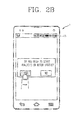
- the controller 11 inquires the user whether to start a motor analysis (refer to FIG. 2B ). If the user presses a 'YES' button (refer to ' ⁇ ' of FIG. 2B ), the controller 11 controls the display unit 15 to guide contact of the mobile terminal 1 to the motor 2 (refer to FIG. 2C ). In FIG. 2C , it is requested that the mobile terminal 1 should be positioned on the motor 2.
- the present invention is not limited to this. Any position can be implemented if vibrations and sound can be obtained as the mobile terminal 1 contacts the motor 2.
- the controller 11 receives vibrations and sound of the motor 2 from the motor recognizing unit 12 and the sound recognizing unit 13, to thus perform an analysis on the received vibrations and sound (refer to FIG. 2F ).
- the controller 11 can analyze a status of the motor 2 by converting the vibrations and sound using FFT.
- Such method for analyzing a status of the motor 2 using vibrations and sound is well known to those skilled in the art, and thus its detailed explanations will be omitted.
- the controller 11 may control the display unit 15 to display a message indicating that a user can use the motor 2 (refer to FIG. 2G ).
- the controller 11 may control the display unit 15 to display a message indicating that the motor 2 should be checked (refer to FIG. 2H).
- FIG. 2H merely illustrates that the motor 2 is required to be checked. However, it is also possible to guide a specific part of the motor 2 to be checked, according to vibrations of the motor 2.
- the controller 11 may store an analysis result relating to the analyzed motor status.
- the mobile terminal 1 may further include a storage unit.
- the apparatus for analyzing a motor status may easily analyze a motor status, using the motion recognizing unit (e.g., motion sensor) and the sound recognizing unit of the mobile terminal 1.
- the motion recognizing unit e.g., motion sensor
- the occurrence of a trip on the inverter may be informed in the form of an application of the mobile terminal 1, which will be explained in more detail.
- FIG. 3 is an exemplary view for explaining a system to which an apparatus for alarming an inverter status according to the present invention is applied
- FIG. 4 is a detailed view showing a configuration of an inverter of FIG. 3 according to an embodiment of the present invention
- FIG. 5 is a view showing a configuration of an apparatus for alarming an inverter status according to an embodiment of the present invention.
- the present invention is applied to a system which interworks between an inverter 3 for driving the motor 2 and the mobile terminal 1.
- the inverter 3 includes a controller 31 and a communication unit 32. It is obvious to those skilled in the art that the inverter 3 includes a plurality of components. However, components irrelevant to the present invention will not be explained.
- the controller 31 In a case where a trip has occurred from the inverter 3, the controller 31 generates a trip signal, and the communication unit 32 transmits the generated trip signal to the mobile terminal 1 through a radio network.
- the inverter 3 and the mobile terminal 1 of the present invention perform wireless communication, e.g., WiFi, 3 rd generation (3G) mobile communication or 4 th generation (4G) mobile communication.
- wireless communication e.g., WiFi, 3 rd generation (3G) mobile communication or 4 th generation (4G) mobile communication.
- 3G 3 rd generation
- 4G 4 th generation
- the apparatus for alarming an inverter status is provided to the mobile terminal 1, and includes a controller 21, a receiving unit 22, a sound output unit 23 and a display unit 24.
- the receiving unit 22 receives a trip signal transmitted from the communication unit 32 of the inverter 3.
- the controller 21 may control the display unit 24 to display the trip signal received by the receiving unit 22, in a viewable manner by a user.
- the controller 21 may control the sound output unit 23 to output the trip signal received by the receiving unit 22, in the form of an alarm sound.
- the controller 21 may control the mobile terminal 1 to vibrate, while the display unit 24 displays an alarm sound with respect to the trip signal.
- the trip signal received by the receiving unit 22 includes information on the inverter 3 which has transmitted the trip signal.
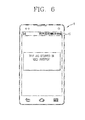
- FIG. 6 is an exemplary view for explaining an alarm message displayed on the display unit according to the present invention.
- the controller 21 may control display of the occurrence of a trip from a prescribed inverter ('ABCD inverter' in FIG. 6 ). However, this is merely exemplary. The controller 21 of the present invention may control display of the occurrence of a trip in other forms.
- the present invention can have the following advantages.
- whether the motor has been broken or not can be determined by analyzing vibrations and sound of the motor using a smart device. This can enhance a portable characteristic, and allow a function for analyzing a motor status to be performed with low costs.
- a trip signal generated when driving the inverter is provided to a user's mobile terminal through wireless communication. This can allow a tripped status of the inverter to be efficiently informed to the user, and can reduce the occurrence of a stopped status of equipment where the inverter is installed. As a result, operation efficiency can be enhanced.
Landscapes
- Engineering & Computer Science (AREA)
- Computer Networks & Wireless Communication (AREA)
- Chemical & Material Sciences (AREA)
- Combustion & Propulsion (AREA)
- Physics & Mathematics (AREA)
- General Physics & Mathematics (AREA)
- Microelectronics & Electronic Packaging (AREA)
- Power Engineering (AREA)
- Control Of Electric Motors In General (AREA)
- Measurement Of Mechanical Vibrations Or Ultrasonic Waves (AREA)
- Telephone Function (AREA)
- Inverter Devices (AREA)
- Control Of Ac Motors In General (AREA)
- Mobile Radio Communication Systems (AREA)
Abstract
Description
- The present disclosure relates to an inverter and a motor technique, and particularly, to an apparatus for alarming an inverter status and an apparatus for analyzing a motor status in a mobile terminal.
- In order to drive a motor, the motor should be generally checked and diagnosed for safety. For analysis of a motor status, additional equipment is required. Such equipment checks a motor status by diagnosing a vibration status of the motor. However, the conventional apparatus for analyzing a motor status is very expensive and has a low portability.
- If the motor is in a good status, a user drives the motor by connecting an inverter to the motor. In case of driving the motor using the inverter, the motor is stopped when a trip occurs, and a message indicating the occurrence of the trip is displayed on an inverter controlling keypad. A user analyzes the cause of the break down based on the message, and re-operates the inverter to drive the motor.
- However, such method has the following problems.
- Firstly, in the occurrence of a trip, a user cannot be real time fed-back. As a result, it is difficult to analyze the cause of the trip, and the motor is in a stopped status for a long time. This may cause losses due to stop of equipment to which the inverter is applied.
- Therefore, an aspect of the detailed description is to provide an apparatus for alarming an inverter status and an apparatus for analyzing a motor status capable of informing an inverter status to a user and analyzing a motor status using a mobile terminal.
- To achieve these and other advantages and in accordance with the purpose of this specification, as embodied and broadly described herein, there is provided an apparatus for analyzing a motor status in a mobile terminal, the apparatus comprising: a first recognition unit configured to recognize vibrations of a motor contacting thereto, and providing the vibrations to a controller; a second recognition unit configured to recognize sound of the motor, and providing the sound to the controller; and the controller configured to analyze a frequency from the vibrations and sound of the motor, to check a change of the vibrations, and thus to obtain an analysis result on a status of the motor.
- According to an embodiment of the present invention, the apparatus may further comprise a display unit configured to display an analysis result on a status of the motor, under control of the controller.
- According to an embodiment of the present invention, the apparatus may further comprise a user input unit having a layered structure with the display unit, and configured to receive a user's input.
- According to an embodiment of the present invention, the controller may obtain an analysis result on a status of the motor using Fast Fourier Transform (FFT).
- According to an embodiment of the present invention, the apparatus may further comprise a storage unit configured to store therein the analysis result on a status of the motor output from the controller.
- To achieve these and other advantages and in accordance with the purpose of this specification, as embodied and broadly described herein, there is provided an apparatus for alarming an inverter status in a mobile terminal, the apparatus capable of informing a tripped status of an inverter, and the apparatus comprising: a receiving unit configured to receive a signal (trip signal) indicating that a trip has occurred from the inverter; a display unit configured to perform a display function under control of the controller; a sound output unit configured to output an alarm sound under control of the controller; and the controller configured to control the display unit to display the trip signal in a viewable manner by a user, and to control the sound output unit to output an alarm sound in an audible manner by the user, when the trip signal is received.
- According to an embodiment of the present invention, preferably, the controller may control the mobile terminal to vibrate when the trip signal is received.
- According to an embodiment of the present invention, preferably, the inverter and the receiving unit may communicate with each other through a wireless network.
- According to an embodiment of the present invention, preferably, the trip signal may include information on the inverter.
- The present invention may have the following advantages.
- Firstly, whether the motor has been broken or not can be determined by analyzing vibrations and sound of the motor using the mobile terminal, a smart device. This can enhance a portable characteristic, and allow a function for analyzing a motor status to be performed with low costs.
- Secondly, a trip signal generated when driving the inverter is provided to a user's mobile terminal through wireless communication. This can allow a tripped status of the inverter to be efficiently informed to the user, and can reduce the occurrence of a stopped status of equipment where the inverter is installed. As a result, operation efficiency can be enhanced.
- Further scope of applicability of the present application will become more apparent from the detailed description given hereinafter. However, it should be understood that the detailed description and specific examples, while indicating preferred embodiments of the invention, are given by way of illustration only, since various changes and modifications within the spirit and scope of the invention will become apparent to those skilled in the art from the detailed description.
- The accompanying drawings, which are included to provide a further understanding of the invention and are incorporated in and constitute a part of this specification, illustrate exemplary embodiments and together with the description serve to explain the principles of the invention.
- In the drawings:
-
FIG. 1 is a view showing a configuration of an apparatus for analyzing a motor status according to an embodiment of the present invention; -
FIGS. 2A to 2H are exemplary views for explaining processes for analyzing a motor status by an apparatus for analyzing a motor status according to the present invention; -
FIG. 3 is an exemplary view for explaining a system to which an apparatus for alarming an inverter status according to the present invention is applied; -
FIG. 4 is a detailed view showing a configuration of an inverter ofFIG. 3 according to an embodiment of the present invention; -
FIG. 5 is a view showing a configuration of an apparatus for alarming an inverter status according to an embodiment of the present invention; and -
FIG. 6 is an exemplary view for explaining an alarm message displayed on a display unit according to the present invention. - Description will now be given in detail of the exemplary embodiments, with reference to the accompanying drawings. For the sake of brief description with reference to the drawings, the same or equivalent components will be provided with the same reference numbers, and description thereof will not be repeated.
- Reference will now be made in detail to the preferred embodiments of the present invention, examples of which are illustrated in the accompanying drawings. It will also be apparent to those skilled in the art that various modifications and variations can be made in the present invention without departing from the spirit or scope of the invention. Thus, it is intended that the present invention cover modifications and variations of this invention provided they come within the scope of the appended claims and their equivalents.
- Though terms of 'first', 'second', etc. are used to explain various components, the components are not limited to the terms. The terms are used only to distinguish one component from another component. For example, a first component may be referred to as a second component, or similarly, the second component may be referred to as the first component within the scope of the present invention.
- When it is mentioned that one component is "connected" or "accessed" to another component, it may be understood that the one component is directly connected or accessed to the another component or that still other component is interposed between the two components. In the meantime, when it is mentioned that one component is "directly connected" or "directly accessed" to another component, it may be understood that no component is interposed therebetween.
- A singular expression includes a plural concept unless there is a contextually distinctive difference therebetween. In the present invention, a term of "include" or "have" should not be interpreted as if it absolutely includes a plurality of components or steps of the specification. Rather, the term of "include" or "have" may not include some components or some steps, or may further include additional components.
- Hereinafter, a preferred embodiment of the present invention will be explained with reference to the attached drawings.
-
FIG. 1 is a view showing a configuration of an apparatus for analyzing a motor status according to an embodiment of the present invention. - As shown, the apparatus for analyzing a
motor status 10 according to an embodiment of the present invention is applied to a mobile terminal 1, and includes acontroller 11, amotion recognizing unit 12, asound recognizing unit 13, a user input unit 14 and adisplay unit 15. - The mobile terminal 1 to which the present invention is applied, is a smart phone, for instance. The mobile terminal 1 may provide a user with an interface in the form of an application. However, the mobile terminal of the present invention is not limited to a smart phone, but may be applied to a mobile terminal having a similar function (e.g., notebook computer, pad type computer, etc.).
- The
motion recognizing unit 12 is provided to the mobile terminal, and is implemented as a motion sensor, for instance. However, themotion recognition unit 12 is not limited to the motion sensor. Themotion recognizing unit 12 recognizes vibrations of a motor contacting thereto, and provides the vibrations to thecontroller 11. - The
sound recognizing unit 13 recognizes sound of a motor positioned close thereto, and provides the recognized sound to thecontroller 11. - The
controller 11 receives vibrations (frequency) of a motor which has contacted thereto from themotion recognizing unit 12, and receives sound of a motor from thesound recognizing unit 13. Based on the received vibrations of the motor, thecontroller 11 checks change of the vibrations to thereby determine whether the motor has broken or not, and to acquire an analysis result on a motor status. - The
controller 11 may analyze a motor status by converting the vibrations and sound using Fast Fourier Transform (FFT). - The
display unit 15 is provided on the front surface of the mobile terminal, and displays an analysis result on a motor status under control of thecontroller 11 so that a user can view the analysis result. Further, thedisplay unit 15 displays an application for analysis so that a user can view the application. - The user input unit 14 is provided in an layered form with the
display unit 15, which is provided on a prescribed position of thedisplay unit 15 in the form of soft keys. A user may perform a key input using the user input unit 14, if he or she wishes to start analyzing a motor status. When the user has performed a key input using the user input unit 14, a signal is transmitted to thecontroller 11. -
FIGS. 2A to 2H are exemplary views for explaining processes for analyzing a motor status by the apparatus for analyzing a motor status according to the present invention. - As shown, an application (A) for analysis by the apparatus for analyzing a motor status according to the present invention, may be provided to the mobile terminal 1. In a case where a user wishes to perform an analysis on a motor status, the application (A) is selected. In the following descriptions, the mark '√' indicates a user's selection. The user input unit 14 receives a user's selection, and provides the user's selection to the
controller 11 as aforementioned. - In a case where a user has selected an application for analyzing a motor status, the
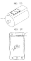
controller 11 inquires the user whether to start a motor analysis (refer toFIG. 2B ). If the user presses a 'YES' button (refer to '√' ofFIG. 2B ), thecontroller 11 controls thedisplay unit 15 to guide contact of the mobile terminal 1 to the motor 2 (refer toFIG. 2C ). InFIG. 2C , it is requested that the mobile terminal 1 should be positioned on themotor 2. However, the present invention is not limited to this. Any position can be implemented if vibrations and sound can be obtained as the mobile terminal 1 contacts themotor 2. - Once the user contacts the mobile terminal 1 to the motor 2 (refer to
FIG. 2D ) and requests for start of an analysis using the user input unit 14 (refer toFIG. 2E ), thecontroller 11 receives vibrations and sound of themotor 2 from themotor recognizing unit 12 and thesound recognizing unit 13, to thus perform an analysis on the received vibrations and sound (refer toFIG. 2F ). - As aforementioned, the
controller 11 can analyze a status of themotor 2 by converting the vibrations and sound using FFT. Such method for analyzing a status of themotor 2 using vibrations and sound is well known to those skilled in the art, and thus its detailed explanations will be omitted. - If the
motor 2 is in a normal status as an analysis result by thecontroller 11, thecontroller 11 may control thedisplay unit 15 to display a message indicating that a user can use the motor 2 (refer toFIG. 2G ). On the other hand, if themotor 2 is in an abnormal status as an analysis result by thecontroller 11, thecontroller 11 may control thedisplay unit 15 to display a message indicating that themotor 2 should be checked (refer toFIG. 2H). FIG. 2H merely illustrates that themotor 2 is required to be checked. However, it is also possible to guide a specific part of themotor 2 to be checked, according to vibrations of themotor 2. - The
controller 11 may store an analysis result relating to the analyzed motor status. For this, the mobile terminal 1 may further include a storage unit. - The apparatus for analyzing a motor status according to the present invention may easily analyze a motor status, using the motion recognizing unit (e.g., motion sensor) and the sound recognizing unit of the mobile terminal 1.
- In case of driving the analyzed motor, the occurrence of a trip on the inverter may be informed in the form of an application of the mobile terminal 1, which will be explained in more detail.
-
FIG. 3 is an exemplary view for explaining a system to which an apparatus for alarming an inverter status according to the present invention is applied,FIG. 4 is a detailed view showing a configuration of an inverter ofFIG. 3 according to an embodiment of the present invention, andFIG. 5 is a view showing a configuration of an apparatus for alarming an inverter status according to an embodiment of the present invention. - As shown in
FIG. 3 , the present invention is applied to a system which interworks between aninverter 3 for driving themotor 2 and the mobile terminal 1. For this, theinverter 3 includes acontroller 31 and acommunication unit 32. It is obvious to those skilled in the art that theinverter 3 includes a plurality of components. However, components irrelevant to the present invention will not be explained. - In a case where a trip has occurred from the
inverter 3, thecontroller 31 generates a trip signal, and thecommunication unit 32 transmits the generated trip signal to the mobile terminal 1 through a radio network. - The
inverter 3 and the mobile terminal 1 of the present invention perform wireless communication, e.g., WiFi, 3rd generation (3G) mobile communication or 4th generation (4G) mobile communication. However, the present invention is not limited to this. - As shown in
FIG. 5 , the apparatus for alarming an inverter status according to the present invention is provided to the mobile terminal 1, and includes acontroller 21, a receivingunit 22, asound output unit 23 and adisplay unit 24. - The receiving
unit 22 receives a trip signal transmitted from thecommunication unit 32 of theinverter 3. Thecontroller 21 may control thedisplay unit 24 to display the trip signal received by the receivingunit 22, in a viewable manner by a user. Alternatively, thecontroller 21 may control thesound output unit 23 to output the trip signal received by the receivingunit 22, in the form of an alarm sound. Although not shown, thecontroller 21 may control the mobile terminal 1 to vibrate, while thedisplay unit 24 displays an alarm sound with respect to the trip signal. - Preferably, the trip signal received by the receiving
unit 22 includes information on theinverter 3 which has transmitted the trip signal. -
FIG. 6 is an exemplary view for explaining an alarm message displayed on the display unit according to the present invention. - The
controller 21 may control display of the occurrence of a trip from a prescribed inverter ('ABCD inverter' inFIG. 6 ). However, this is merely exemplary. Thecontroller 21 of the present invention may control display of the occurrence of a trip in other forms. - The present invention can have the following advantages.
- Firstly, whether the motor has been broken or not can be determined by analyzing vibrations and sound of the motor using a smart device. This can enhance a portable characteristic, and allow a function for analyzing a motor status to be performed with low costs.
- Secondly, a trip signal generated when driving the inverter is provided to a user's mobile terminal through wireless communication. This can allow a tripped status of the inverter to be efficiently informed to the user, and can reduce the occurrence of a stopped status of equipment where the inverter is installed. As a result, operation efficiency can be enhanced.
- The foregoing embodiments and advantages are merely exemplary and are not to be considered as limiting the present disclosure. The present teachings can be readily applied to other types of apparatuses. This description is intended to be illustrative, and not to limit the scope of the claims. Many alternatives, modifications, and variations will be apparent to those skilled in the art. The features, structures, methods, and other characteristics of the exemplary embodiments described herein may be combined in various ways to obtain additional and/or alternative exemplary embodiments.
- As the present features may be embodied in several forms without departing from the characteristics thereof, it should also be understood that the above-described embodiments are not limited by any of the details of the foregoing description, unless otherwise specified, but rather should be considered broadly within its scope as defined in the appended claims, and therefore all changes and modifications that fall within the metes and bounds of the claims, or equivalents of such metes and bounds are therefore intended to be embraced by the appended claims.
Claims (9)
- An apparatus for analyzing a motor status in a mobile terminal, the apparatus comprising:a first recognition unit configured to recognize vibrations of a motor contacting thereto, and providing the vibrations to a controller;a second recognition unit configured to recognize sound of the motor, and providing the sound to the controller; andthe controller configured to analyze a frequency from the vibrations and sound of the motor, to check a change of the vibrations, and thus to obtain an analysis result on a status of the motor.
- The apparatus of claim 1, further comprising a display unit configured to display an analysis result on a status of the motor, under control of the controller
- The apparatus of any of claims 1 to 2, further comprising a user input unit having a layered structure with the display unit, and configured to receive a user's input.
- The apparatus of any of claims 1 to 3, wherein the controller obtains an analysis result on a status of the motor using Fast Fourier Transform (FFT).
- The apparatus of any of claims 1 to 4, further comprising a storage unit configured to store therein the analysis result on a status of the motor output from the controller.
- An apparatus for alarming an inverter status in a mobile terminal, the apparatus capable of informing a tripped status of an inverter and, and the apparatus comprising:a receiving unit configured to receive a signal (trip signal) indicating that a trip has occurred from the inverter;a display unit configured to perform a display function under control of the controller;a sound output unit configured to output an alarm sound under control of the controller; andthe controller configured to control the display unit to display the trip signal in a viewable manner by a user, and to control the sound output unit to output an alarm sound in an audible manner by the user, when the trip signal is received.
- The apparatus of claim 6, wherein the controller controls the mobile terminal to vibrate when the trip signal is received.
- The apparatus of any of claims 6 to 7, wherein the inverter and the receiving unit communicate with each other through a wireless network.
- The apparatus of any of claims 6 to 8, wherein the trip signal includes information on the inverter.
Applications Claiming Priority (1)
| Application Number | Priority Date | Filing Date | Title |
|---|---|---|---|
| KR1020120037806A KR20130115488A (en) | 2012-04-12 | 2012-04-12 | Apparatus for alarming inverter status and apparatus for analyzing motor status in mobile terminal |
Publications (2)
| Publication Number | Publication Date |
|---|---|
| EP2650667A2 true EP2650667A2 (en) | 2013-10-16 |
| EP2650667A3 EP2650667A3 (en) | 2013-11-13 |
Family
ID=48430441
Family Applications (1)
| Application Number | Title | Priority Date | Filing Date |
|---|---|---|---|
| EP13162529.5A Ceased EP2650667A3 (en) | 2012-04-12 | 2013-04-05 | Apparatus for alarming inverter status and apparatus for analyzing motor status in mobile terminal |
Country Status (5)
| Country | Link |
|---|---|
| US (1) | US9407128B2 (en) |
| EP (1) | EP2650667A3 (en) |
| JP (1) | JP2013223243A (en) |
| KR (1) | KR20130115488A (en) |
| CN (1) | CN103376411B (en) |
Cited By (2)
| Publication number | Priority date | Publication date | Assignee | Title |
|---|---|---|---|---|
| EP3547514A4 (en) * | 2016-11-25 | 2020-07-22 | Hitachi, Ltd. | POWER CONVERSION DEVICE |
| EP3996259A1 (en) | 2020-11-06 | 2022-05-11 | Siemens Aktiengesellschaft | Method for monitoring the operation of a drive component |
Families Citing this family (11)
| Publication number | Priority date | Publication date | Assignee | Title |
|---|---|---|---|---|
| FR3021109B1 (en) * | 2014-05-19 | 2017-12-15 | Ntn-Snr Roulements | METHOD FOR MONITORING AN INDUSTRIAL INSTALLATION AND ASSOCIATED INSTRUMENTATION INTERFACE |
| EP2890000A3 (en) * | 2015-03-04 | 2015-10-14 | ABB Technology Oy | Frequency converter and drive system |
| US9799320B2 (en) | 2015-09-24 | 2017-10-24 | Fuji Xerox Co., Ltd. | Mobile terminal apparatus and non-transitory computer readable medium |
| JP5954648B1 (en) * | 2016-01-08 | 2016-07-20 | 富士ゼロックス株式会社 | Terminal device, diagnostic system, and program |
| KR102528486B1 (en) * | 2016-09-21 | 2023-05-03 | 주식회사 대흥기전 | System for monitoring remotely emergency generator in interworking with smartphone providing screen switching based on UVR signal |
| KR102042570B1 (en) * | 2018-04-03 | 2019-11-27 | 엘지전자 주식회사 | water purifying apparatus and method for controlling water purifying apparatus |
| CN108680860A (en) * | 2018-07-23 | 2018-10-19 | 五邑大学 | A kind of EPS motor fault detection method |
| CN110530502A (en) * | 2019-08-01 | 2019-12-03 | 深圳市无限动力发展有限公司 | Motor status monitoring method, device, storage medium and computer equipment |
| KR102502005B1 (en) * | 2020-12-01 | 2023-02-21 | 오성균 | Smartphone Sensor-Based Methods and Systems for Measuring Engine Condition |
| KR102553716B1 (en) | 2022-12-29 | 2023-07-10 | 유미희 | Motor state detection system in which the magnet and magnetic switch are located on two different planes |
| CN121219956A (en) * | 2023-06-02 | 2025-12-26 | 索尤若驱动有限及两合公司 | Systems with drivers and smartphones |
Citations (4)
| Publication number | Priority date | Publication date | Assignee | Title |
|---|---|---|---|---|
| US5902342A (en) * | 1997-03-27 | 1999-05-11 | Abb Daimler-Benz Transportation (North America) Inc. | Detection of vibration in an AC traction system |
| US20030171827A1 (en) * | 2002-03-06 | 2003-09-11 | Keyes Marion A. | Appendable system and devices for data acquisition, analysis and control |
| US20100056224A1 (en) * | 2008-08-18 | 2010-03-04 | Lg Electronics Inc. | Mobile terminal and method of controlling the same |
| US20110032073A1 (en) * | 2005-08-24 | 2011-02-10 | Homerun Holdings, Corp. | System and Methods for Automatically Moving Access Barriers Initiated by Mobile Transmitter Devices |
Family Cites Families (18)
| Publication number | Priority date | Publication date | Assignee | Title |
|---|---|---|---|---|
| JPS6264919A (en) | 1985-09-18 | 1987-03-24 | Fuji Electric Co Ltd | Simple vibration monitor apparatus |
| US5852351A (en) * | 1996-08-22 | 1998-12-22 | Csi Technology | Machine monitor |
| US5992237A (en) | 1997-07-22 | 1999-11-30 | Skf Condition Monitoring, Inc. | Digital vibration coupling stud |
| US6199018B1 (en) * | 1998-03-04 | 2001-03-06 | Emerson Electric Co. | Distributed diagnostic system |
| US6484109B1 (en) | 1998-05-20 | 2002-11-19 | Dli Engineering Coporation | Diagnostic vibration data collector and analyzer |
| JP4490595B2 (en) | 2001-03-14 | 2010-06-30 | 株式会社日立産機システム | Inverter management system |
| US7228129B1 (en) | 2001-03-20 | 2007-06-05 | Logical Concepts, Inc. | Expert system for monitoring, recording and controlling remote equipment that minimizes wireless telephone airtime |
| JP3864146B2 (en) | 2003-03-18 | 2006-12-27 | 株式会社東芝 | Bearing diagnosis device for rotating machine, bearing diagnosis system for rotating machine, portable terminal and function expansion card |
| JP2006079311A (en) | 2004-09-09 | 2006-03-23 | Matsushita Electric Ind Co Ltd | Information terminal and program |
| JP4555065B2 (en) | 2004-12-16 | 2010-09-29 | 東芝シュネデール・インバータ株式会社 | Inverter system |
| US20080221784A1 (en) | 2005-05-25 | 2008-09-11 | Meir Ezra | Measurement of Fuel Consumed and of Distance Travelled |
| US8136402B2 (en) * | 2007-11-28 | 2012-03-20 | International Business Machines Corporation | Accelerometer module for use with a touch sensitive device |
| GB0801868D0 (en) * | 2008-02-01 | 2008-03-12 | Black & Decker Inc | Power tool having motor speed monitor |
| DE102009022107A1 (en) * | 2009-05-20 | 2010-11-25 | Ksb Ag | Method and device for determining the operating point of a work machine |
| US9014685B2 (en) * | 2009-06-12 | 2015-04-21 | Microsoft Technology Licensing, Llc | Mobile device which automatically determines operating mode |
| JP5002645B2 (en) | 2009-12-02 | 2012-08-15 | 株式会社日立産機システム | Inverter purchase system |
| JP2011191181A (en) | 2010-03-15 | 2011-09-29 | Toshiba Industrial Products Manufacturing Corp | Abnormality diagnostic system of rotary apparatus, abnormality diagnostic device of the same, and abnormality diagnosis method of the same |
| CH702943A2 (en) | 2010-04-07 | 2011-10-14 | Martin Hofer | Integral, remote controlled device for controlling e.g. radio receiving module for protecting passenger car against theft, has portable control device controlling or regulating safety components that are mounted at car in fixed manner |
-
2012
- 2012-04-12 KR KR1020120037806A patent/KR20130115488A/en not_active Ceased
-
2013
- 2013-04-04 US US13/857,041 patent/US9407128B2/en not_active Expired - Fee Related
- 2013-04-05 EP EP13162529.5A patent/EP2650667A3/en not_active Ceased
- 2013-04-10 JP JP2013082336A patent/JP2013223243A/en active Pending
- 2013-04-12 CN CN201310127810.9A patent/CN103376411B/en not_active Expired - Fee Related
Patent Citations (4)
| Publication number | Priority date | Publication date | Assignee | Title |
|---|---|---|---|---|
| US5902342A (en) * | 1997-03-27 | 1999-05-11 | Abb Daimler-Benz Transportation (North America) Inc. | Detection of vibration in an AC traction system |
| US20030171827A1 (en) * | 2002-03-06 | 2003-09-11 | Keyes Marion A. | Appendable system and devices for data acquisition, analysis and control |
| US20110032073A1 (en) * | 2005-08-24 | 2011-02-10 | Homerun Holdings, Corp. | System and Methods for Automatically Moving Access Barriers Initiated by Mobile Transmitter Devices |
| US20100056224A1 (en) * | 2008-08-18 | 2010-03-04 | Lg Electronics Inc. | Mobile terminal and method of controlling the same |
Cited By (4)
| Publication number | Priority date | Publication date | Assignee | Title |
|---|---|---|---|---|
| EP3547514A4 (en) * | 2016-11-25 | 2020-07-22 | Hitachi, Ltd. | POWER CONVERSION DEVICE |
| EP3996259A1 (en) | 2020-11-06 | 2022-05-11 | Siemens Aktiengesellschaft | Method for monitoring the operation of a drive component |
| WO2022096233A1 (en) | 2020-11-06 | 2022-05-12 | Siemens Aktiengesellschaft | Method for monitoring the operation of a drive component |
| US11962203B2 (en) | 2020-11-06 | 2024-04-16 | Siemens Aktiengesellschaft | Method for monitoring the operation of a drive component |
Also Published As
| Publication number | Publication date |
|---|---|
| JP2013223243A (en) | 2013-10-28 |
| US9407128B2 (en) | 2016-08-02 |
| EP2650667A3 (en) | 2013-11-13 |
| CN103376411B (en) | 2016-12-28 |
| US20130271052A1 (en) | 2013-10-17 |
| KR20130115488A (en) | 2013-10-22 |
| CN103376411A (en) | 2013-10-30 |
Similar Documents
| Publication | Publication Date | Title |
|---|---|---|
| US9407128B2 (en) | Apparatus for alarming inverter status and apparatus for analyzing motor status in mobile terminal | |
| US8150318B2 (en) | Apparatus for collecting environmental data and method of monitoring environment in real time | |
| EP2661019B1 (en) | Method for operating a portable terminal | |
| US20160178479A1 (en) | Dynamic diagnostic indicator generation | |
| JP2016504899A (en) | Electronic device, battery protection method, facility, program, and recording medium | |
| WO2015014293A1 (en) | Devices and methods for guarding against theft of mobile terminals | |
| US20150314791A1 (en) | Method and system for driver tailored interaction time alert | |
| CN105336107A (en) | Vibration alarm method and device | |
| CN108134838A (en) | Data reporting method, device, mobile terminal and computer readable medium | |
| US10637302B2 (en) | Wireless power transmission device and wireless charging system, and method of controlling the same | |
| JP2018528870A (en) | Electric machine tool communication device, electric tool system, and method | |
| KR20200081796A (en) | Method and apparatus for determining abnormal of equipment by using current sensor and vibration sensor pattern information | |
| CN103477328A (en) | Terminal device, control device, malfunction determination system, and method for determining malfunction | |
| EP3606018B1 (en) | Mobile apparatus, information processing method, mobile device program | |
| CN105088647A (en) | Washing machine and method and system for acquiring fault information thereof | |
| EP2876886A1 (en) | Methods and systems to notify user of a problem with a remote control | |
| JP2016201894A (en) | Charge system, power transmitter, power receiver, communication equipment, power transmission control program, power reception control program and communication control program | |
| EP3155794B1 (en) | Signaling system for user device | |
| KR101609777B1 (en) | Earphone wearing identifying method, apparatus, and computer readable recording medium | |
| CN106126110B (en) | Terminal service control method, control device and terminal | |
| KR20170121029A (en) | Audio apparatus and Method for controlling the audio apparatus thereof | |
| KR100594118B1 (en) | Self-diagnosis information display method through self-diagnosis device and portable terminal | |
| JP2017017545A (en) | Call system and telephone | |
| CN112946728A (en) | Method and device for protecting and controlling vibration work of controllable seismic source vibrator | |
| CN112311875A (en) | Vehicle monitoring system |
Legal Events
| Date | Code | Title | Description |
|---|---|---|---|
| PUAL | Search report despatched |
Free format text: ORIGINAL CODE: 0009013 |
|
| PUAI | Public reference made under article 153(3) epc to a published international application that has entered the european phase |
Free format text: ORIGINAL CODE: 0009012 |
|
| AK | Designated contracting states |
Kind code of ref document: A2 Designated state(s): AL AT BE BG CH CY CZ DE DK EE ES FI FR GB GR HR HU IE IS IT LI LT LU LV MC MK MT NL NO PL PT RO RS SE SI SK SM TR |
|
| AX | Request for extension of the european patent |
Extension state: BA ME |
|
| AK | Designated contracting states |
Kind code of ref document: A3 Designated state(s): AL AT BE BG CH CY CZ DE DK EE ES FI FR GB GR HR HU IE IS IT LI LT LU LV MC MK MT NL NO PL PT RO RS SE SI SK SM TR |
|
| AX | Request for extension of the european patent |
Extension state: BA ME |
|
| RIC1 | Information provided on ipc code assigned before grant |
Ipc: B60R 25/102 20130101ALI20131009BHEP Ipc: G01M 15/12 20060101AFI20131009BHEP |
|
| 17P | Request for examination filed |
Effective date: 20140331 |
|
| RBV | Designated contracting states (corrected) |
Designated state(s): AL AT BE BG CH CY CZ DE DK EE ES FI FR GB GR HR HU IE IS IT LI LT LU LV MC MK MT NL NO PL PT RO RS SE SI SK SM TR |
|
| 17Q | First examination report despatched |
Effective date: 20171215 |
|
| STAA | Information on the status of an ep patent application or granted ep patent |
Free format text: STATUS: THE APPLICATION HAS BEEN REFUSED |
|
| 18R | Application refused |
Effective date: 20201210 |