EP2650665A2 - Supercooled large drop icing condition simulation system - Google Patents
Supercooled large drop icing condition simulation system Download PDFInfo
- Publication number
- EP2650665A2 EP2650665A2 EP13158805.5A EP13158805A EP2650665A2 EP 2650665 A2 EP2650665 A2 EP 2650665A2 EP 13158805 A EP13158805 A EP 13158805A EP 2650665 A2 EP2650665 A2 EP 2650665A2
- Authority
- EP
- European Patent Office
- Prior art keywords
- water
- drops
- icing
- nozzles
- properties
- Prior art date
- Legal status (The legal status is an assumption and is not a legal conclusion. Google has not performed a legal analysis and makes no representation as to the accuracy of the status listed.)
- Granted
Links
Images





Classifications
-
- G—PHYSICS
- G01—MEASURING; TESTING
- G01M—TESTING STATIC OR DYNAMIC BALANCE OF MACHINES OR STRUCTURES; TESTING OF STRUCTURES OR APPARATUS, NOT OTHERWISE PROVIDED FOR
- G01M9/00—Aerodynamic testing; Arrangements in or on wind tunnels
- G01M9/02—Wind tunnels
- G01M9/04—Details
-
- F—MECHANICAL ENGINEERING; LIGHTING; HEATING; WEAPONS; BLASTING
- F25—REFRIGERATION OR COOLING; COMBINED HEATING AND REFRIGERATION SYSTEMS; HEAT PUMP SYSTEMS; MANUFACTURE OR STORAGE OF ICE; LIQUEFACTION SOLIDIFICATION OF GASES
- F25C—PRODUCING, WORKING OR HANDLING ICE
- F25C1/00—Producing ice
Definitions
- the present disclosure relates generally to icing conditions and, in particular, to simulating icing conditions. Still more particularly, the present disclosure relates to a method and apparatus for simulating icing conditions in which supercooled large drops are present.
- icing on an aircraft may occur when the atmospheric conditions lead to the formation of ice on the surfaces of the aircraft. Further, this ice also may occur within the engine. Ice formation on the surfaces of the aircraft, on inlets of an engine, and other locations is undesirable and potentially unsafe for operating the aircraft.
- Icing conditions may occur when drops of supercooled liquid water are present.
- water is considered to be supercooled when the water is cooled below the stated freezing point for water but the water is still in a liquid form.
- Icing conditions may be characterized by the size of the drops, the liquid water content, the air temperature, and/or other parameters. These parameters may affect the rate and extent at which ice forms on an aircraft.
- Drops of water may be supercooled in various environments. For example, drops of water may be supercooled in stratiform clouds and in cumulous clouds.
- the aircraft may not operate as desired. For example, ice on the wing of an aircraft will cause the aircraft to stall at a lower angle of attack and have an increased drag.
- Aircraft may have mechanisms to prevent icing, remove ice, or some combination thereof to handle these icing conditions.
- aircraft may include icing detection, prevention, and removal systems. Ice may be removed using bleed air, infrared heating, and other suitable mechanisms.
- Aircraft may have sensor systems designed to detect icing conditions. As new regulations are developed with respect to icing conditions that should be detected, manufacturers design and test sensor systems for detecting the icing conditions. For example, aircraft may be required to be certified to operate in normal icing conditions and in supercooled large drop icing conditions.
- test environments may not provide an ability to simulate supercooled large drop icing conditions in the manner desired to test new sensor systems. Therefore, it would be desirable to have a method and apparatus that takes into account at least some of the issues discussed above as well as possibly other issues.
- an icing simulation system comprises a wind tunnel, a nozzle system, and a controller.
- the nozzle system is configured to spray drops of water within the wind tunnel.
- the controller is configured to control a number of properties of the water in the nozzle system such that the nozzle system sprays the drops of water with different sizes for a desired type of icing condition.
- a method for simulating a desired type of icing condition in a wind tunnel is present.
- a number of properties is controlled for water sent to a nozzle system.
- the number of properties is controlled such that drops of the water have different sizes associated with the desired type of icing condition.
- the drops of water are sprayed from the nozzle system in the wind tunnel.
- the drops of the water sprayed by the nozzle system have different sizes for the desired type of icing condition.
- the illustrative embodiments recognize and take into account one or more different considerations. For example, the illustrative embodiments recognize and take into account that currently available systems for simulating icing conditions are unable to simulate supercooled large drop icing conditions. In particular, the illustrative embodiments recognize and take into account that simulating this type of icing condition involves generating drops of water having two ranges of sizes. These ranges may be two different distributions of water drop sizes. This type of distribution may take the form of a supercooled large drop bimodal distribution.
- the illustrative embodiments recognize and take into account that currently available wind tunnels used to simulate icing conditions are unable to generate drops of water having the two ranges of sizes for supercooled large drop icing conditions.
- an icing simulation system comprises a wind tunnel, a nozzle system, and a controller.
- the nozzle system is configured to spray drops of water within the wind tunnel.
- the controller is configured to control a number of properties of the water in the nozzle system such that the nozzle system sprays the drops of water with different sizes for a desired type of icing condition.
- icing simulation environment 100 may be used to simulate types of icing conditions 102.
- test object 103 may be, for example, structure 104, platform 106, or both.
- Structure 104 may be a structure in platform 106.
- structure 104 may be a structure in aircraft 108.
- structure 104 may be a wing, a horizontal stabilizer, a vertical stabilizer, an engine, a landing gear system, a fuselage, a flap, an aircraft windshield, or some other suitable structure.
- icing simulation system 110 may be used to simulate desired type of icing condition 111 in one or more of types of icing conditions 102 for test object 103.
- Desired type of icing condition 111 is a type of icing condition for which testing is desired with respect to test object 103.
- icing simulation system 110 may be used to simulate desired type of icing condition 111 as first type of icing condition 112, second type of icing condition 114, or both.
- first type of icing condition 112 and second type of icing condition 114 in types of icing conditions 102 may differ from each other based on drop size.
- the drop size may differ based on a mean volumetric diameter. More specifically, the drop sizes may differ based on ranges of sizes.
- first type of icing condition 112 may have one range of sizes
- second type of icing condition 114 may have another range of sizes.
- the distribution of sizes within the ranges also may be used to define different types of icing conditions.
- first type of icing condition 112 may be present when the size of the drops is from about 0.00465 millimeters in diameter to about 0.111 millimeters in diameter. Drops with these sizes may be referred to as normal drops.
- Second type of icing condition 114 may be present when the size of the drops includes drops that have a diameter greater than about 0.111 millimeters. Drops having a size greater than about 0.111 millimeters may be referred to as large drops and, in particular, may be called supercooled large drops under the altitude, temperature, and liquid water content conditions described above. For example, the drops may have a diameter in a range from about 0.112 millimeters to about 2.2 millimeters.
- second type of icing condition 114 may include drops that are 0.111 millimeters or less when drops greater than 0.111 millimeters are present. In other words, second type of icing condition 114 includes both normal drops and large drops of water.
- liquid water content in the drops may also be used to characterize the type of icing condition.
- first type of icing condition 112 may have liquid water content in the range of about 0.04 grams per cubic meter to about 2.8 grams per cubic meter.
- second type of icing condition 114 may have liquid water content in the range of about 0.19 grams per cubic meter to about 0.44 grams per cubic meter.
- icing simulation system 110 is a physical system that also may include software. Icing simulation system 110 includes wind tunnel 116, air drive system 118, cooling system 120, nozzle system 122, sensor system 123, water source 124, air source 126, infrastructure 127, controller 128, and other suitable components.
- air drive system 118 causes air 129 to flow within wind tunnel 116.
- Cooling system 120 may cool the temperature of air 129 within wind tunnel 116.
- Infrastructure 127 comprises components that carry water 130 and air 134 to nozzle system 122.
- infrastructure 127 connects water source 124 and air source 126 to nozzle system 122.
- infrastructure 127 also may be connected to cooling system 120.
- the connection to cooling system 120 may be used to cool water 130, air 134, or both.
- infrastructure 127 also may be connected to cooling system 120.
- the connection to cooling system 120 may be used to cool water 130, air 134, or both.
- Nozzle system 122 receives water 130 from water source 124 through infrastructure 127 and generates drops 132 of water 130. In other words, drops 132 of water 130 are generated by water 130 flowing through nozzle system 122.
- air 134 received through infrastructure 127 may be introduced into water 130 as water 130 flows through nozzle system 122 to form drops 132 of water 130.
- air source 126 also may send air 134 to nozzle system 122 via infrastructure 127.
- air 134 may be mixed with water 130 to form drops 132 of water 130 sprayed by nozzle system 122.
- drops 132 of water 130 generated by nozzle system 122 may have properties 136 to simulate first type of icing condition 112, second type of icing condition 114, or both.
- properties 136 of drops 132 of water 130 may include, for example, without limitation, size, water content, temperature, and other suitable properties.
- Sensor system 123 is configured to generate data about one or more of properties 136 of drops 132 of water 130. In other words, sensor system 123 identifies properties 136 of drops 132 of water 130 generated by nozzle system 122 within wind tunnel 116 .
- Controller 128 is configured to control properties 140 of water 130 to simulate at least one of first type of icing condition 112, second type of icing condition 114, or both.
- Controller 128 may use data from sensor system 123 to adjust values for a number of properties in properties 140 of water 130 to obtain desired type of icing condition 111 within types of icing conditions 102.
- sensor system 123 provides feedback to controller 128 about drops 132 of water 130.
- the data received from sensor system 123 may be used to adjust properties 140 of water 130 if properties 136 for drops 132 of water 130 do not have desired values for desired type of icing condition 111.
- the adjustment of properties 140 of water 130 made by controller 128 may be made at different times during testing. For example, the adjustment may be made prior to placing test object 103 into wind tunnel 116 for testing of desired type of icing condition 111. Additionally, these adjustments may be made while the simulation of desired type of icing condition 111 is performed on test object 103. In other words, adjustments may be made dynamically during the testing to maintain desired type of icing condition 111.
- controller 128 is comprised of hardware, software, or both.
- controller 128 may be a computer system.
- the computer system may include one or more computers. When more than one computer is present in the computer system, those computers may be in communication with each other through a network.
- controller 128 may be implemented using hardware with circuits configured to perform operations to simulate types of icing conditions 102.
- the hardware may take the form of a circuit system, an integrated circuit, an application specific integrated circuit (ASIC), a programmable logic device, or some other suitable type of hardware configured to perform a number of operations.
- ASIC application specific integrated circuit
- the device is configured to perform the number of operations.
- the device may be reconfigured at a later time or may be permanently configured to perform the number of operations.
- programmable logic devices include, for example, a programmable logic array, a programmable array logic, a field programmable logic array, a field programmable gate array, and other suitable hardware devices.
- the processes may be implemented in organic components integrated with inorganic components and/or may be comprised entirely of organic components excluding a human being.
- test object 103 may be placed in test area 142 in wind tunnel 116 for exposure to drops 132 of water 130.
- drops 132 of water 130 may be generated by properties 136 to simulate desired type of icing condition 111.
- test object 103 may be an airfoil with sensors configured to detect icing conditions.
- desired type of icing condition 111 may be a supercooled large drop icing condition.
- FIG. 2 an illustration of a block diagram of properties controlled by a controller is depicted in accordance with an illustrative embodiment.
- properties 140 of water 130 that may be controlled by controller 128 to obtain properties 136 for drops 132 to simulate desired type of icing condition 111 in types of icing conditions 102 in Figure 1 are shown in this illustrative example.
- properties 140 include at least one of water pressure 202, air pressure 204, air flow 206, temperature 208, and other suitable properties.
- Properties 140 controlled by controller 128 may be selected from one or more of properties 140.
- Water pressure 202 is the pressure of water 130 in nozzle system 122 in Figure 1 .
- Air pressure 204 is the pressure of air 134 introduced into nozzle system 122.
- Air flow 206 is the speed at which air moves within wind tunnel 116.
- Temperature 208 is the temperature of water 130 in nozzle system 122. Temperature 208 may be selected to be near or below freezing for water 130 prior to water 130 being sprayed as drops 132 from nozzle system 122. The selection of temperature 208 is such that water 130 does not freeze within nozzles in nozzle system 122.
- values for at least one of water pressure 202, air pressure 204, and air flow 206 of properties 140 may be selected to obtain properties 136 of drops 132 that are desired for desired type of icing condition 111.
- These properties may include at least one of, for example, without limitation, size, water content, temperature, and other suitable properties for drops 132 of water 130 in a manner that produces desired type of icing condition 111 in types of icing conditions 102.
- the values for properties 140 may change, depending on the particular type of icing condition in types of icing conditions 102. In other words, the values of properties 140 selected for first type of icing condition 112 are different from the values of properties 140 selected for second type of icing condition 114.
- air pressure 204 may be from about 10 psi to about 60 psi
- water pressure 202 may be from about 20 psi to about 240 psi.
- This combination of air pressure 204 and water pressure 202 may produce water drops having sizes of up to about 0.050 millimeters. The size of the water drops may be increased by changing the pressure of the water relative to the pressure of the air.
- air pressure 204 may be changed by a magnitude relative to water pressure 202.
- water pressure 202 may be about 80 psi
- air pressure 204 may be about 8 psi.
- the drops of water may be about 0.500 millimeters.
- air pressure 204 may be from about 10 psi to about 60 psi.
- Water pressure 202 may be from about 10 psi to about 240 psi.
- the values of water pressure 202 and air pressure 204 may change, depending on the types of nozzles used.
- FIG. 3 an illustration of a block diagram of a nozzle system is depicted in accordance with an illustrative embodiment. Examples of components for nozzle system 122 are illustrated in this figure.
- nozzle system 122 is comprised of groups of nozzles 300 and support structures 301.
- a group of nozzles within groups of nozzles 300 includes one or more nozzles.
- one group of nozzles within groups of nozzles 300 may have a different number of nozzles than another group of nozzles within groups of nozzles 300.
- Support structures 301 are configured to be associated with groups of nozzles 300.
- the association is a physical association in these depicted examples.
- a first component, group of nozzles 304 in groups of nozzles 300 may be considered to be associated with a second component, support structure 306 in support structures 301, by being secured to the second component, bonded to the second component, mounted to the second component, welded to the second component, fastened to the second component, and/or connected to the second component in some other suitable manner.
- the first component also may be connected to the second component using a third component.
- the first component may also be considered to be associated with the second component by being formed as part of and/or an extension of the second component.
- the association may be a temporary association in which the first component may be removed from the second component or vice versa.
- Support structures 301 may also be configured to receive water and direct water to groups of nozzles 300.
- support structures 301 may include lines, valves, or other components that may be used to control the flow of water within support structures 301.
- support structures 301 also may include sensors used to generate data about water flowing through support structures 301.
- the association of groups of nozzles 300 with support structures 301 forms plurality of spray bars 302.
- Each group of nozzles in groups of nozzles 300 is associated with a support structure in support structures 301.
- the association of group of nozzles 304 with support structure 306 forms spray bar 308.
- properties 140 in Figure 2 may be controlled with different levels of granularity.
- each group of nozzles in groups of nozzles 300 may have different values for properties 140 as compared to other groups of nozzles.
- values for properties 140 may be controlled individually for each nozzle in group of nozzles 304.
- one group of nozzles in groups of nozzles 300 may spray drops 132 of water 130 in Figure 1 with a different size or range of sizes as compared to another group of nozzles in groups of nozzles 300 through the control of properties 140 for these two groups of nozzles.
- the sizes of drops 132 of water 130 may be achieved using groups of nozzles 300 to obtain a desired type of icing condition within types of icing conditions 102 in Figure 1 .
- FIG. 4 an illustration of a block diagram of an infrastructure in an icing simulation system is depicted in accordance with an illustrative embodiment.
- examples of some components that may be present in infrastructure 127 include lines 400, valves 402, and sensors 403 are shown.
- Lines 400 may include, for example, flexible lines 404 and rigid lines 406.
- lines 400 may be used to connect water source 124 and air source 126 to nozzle system 122 in Figure 1 . Further, some of lines 400 may be connected to cooling system 120 in Figure 1 .
- Valves 402 are associated with lines 400. Valves 402 may be operated to control the flow of fluids through lines 400. In these illustrative examples, these fluids may be water 130 and air 134 in Figure 1 . In these illustrative examples, the operation of valves 402 is controlled by controller 128. Controller 128 operates valves 402 to select values for properties 140 in Figure 1 .
- Sensors 403 are configured to detect the values of properties 140. Additionally, sensors 403 also may be configured to detect the position of valves 402, the flow of liquids through lines 400, and other suitable parameters.
- sensors 403 may be associated with lines 400 and valves 402. Further, sensors 403 also may be associated with nozzle system 122.
- Sensors 403 generate data 408 that is sent to controller 128. Controller 128 operates valves 402 to adjust the values of properties 140.
- icing simulation environment 100 in Figure 1 and the components of icing simulation environment 100 in Figures 1-4 are not meant to imply physical or architectural limitations to the manner in which an illustrative embodiment may be implemented. Other components in addition to or in place of the ones illustrated may be used. Some components may be unnecessary. Also, the blocks are presented to illustrate some functional components. One or more of these blocks may be combined, divided, or combined and divided into different blocks when implemented in an illustrative embodiment.
- test object 103 may be placed in test area 142 during simulation of desired type of icing condition 111 using icing simulation system 110.
- test object 103 may take other forms other than an aircraft or objects that are for or part of an aircraft.
- test object 103 may be selected from one of an automobile windshield, automobile, a ship, an engine hood, a deck of a ship, and other suitable test objects.
- valves 402, sensors 403, or both may be considered part of controller 128.
- additional types of icing conditions in addition to or in place of first type of icing condition 112 and second type of icing condition 114 in types of icing conditions 102 may be present.
- three or more ranges of sizes for drops 132 of water 130 may be present for those types of icing conditions.
- icing simulation system 500 is one example of a physical implementation for icing simulation system 110 shown in block form in Figure 1 .
- icing simulation system 500 includes wind tunnel 502, air drive system 504, nozzle system 506, cooling system 508, and controller 510.
- wind tunnel 502 has turning vane 512, turning vane 514, turning vane 516, and turning vane 518. These turning vanes aid in directing air flow 520 generated by air drive system 504 to turn or curve within wind tunnel 502.
- air flow 520 is generated by air drive system 504.
- air drive system 504 comprises fan system 522.
- nozzle system 506 comprises spray bars 524.
- spray bars 524 are configured to spray drops of water 526 within wind tunnel 502. Drops of water 526 are carried by air flow 520 through test section 528 within wind tunnel 502.
- cooling system 508 comprises refrigeration system 530 and heat exchanger 532.
- Refrigeration system 530 and heat exchanger 532 operate to cool air within air flow 520 passing by or through heat exchanger 532.
- sensor system 509 takes the form of laser sensor system 534.
- Laser sensor system 534 sends laser beam 536 into wind tunnel 502 where drops of water 526 are generated by spray bars 524 in nozzle system 506.
- Laser sensor system 534 sends data about sizes of drops of water 526 to controller 510 in control room 538.
- controller 510 may adjust properties of water sent through spray bars 524 in nozzle system 506 to obtain desired sizes for drops of water 526 to simulate a desired type of icing condition.
- drops of water 526 may have two ranges of sizes for the desired icing condition.
- the desired icing condition may be a supercooled large drop icing condition.
- drops of water 526 may include sizes for normal drops and sizes for supercooled large drops.
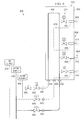
- spray bar balancing system 600 may be implemented in a number of different places within icing simulation system 110 in Figure 1 .
- spray bar balancing system 600 may be implemented as part of infrastructure 127, nozzle system 122, or a combination of the two in Figure 1 .
- spray bar balancing system 600 may be used to control spray bar 602 in a manner that allows for drops 604 of water to be produced with a desired size and temperature more quickly to form a desired icing cloud for a desired type of icing condition.
- the drop size may be defined by the mean volumetric diameter of the drops of water and/or the liquid water content in the drops of water. These parameters are functions of the pressure of air in spray bar 602 and the change in pressure of air in spray bar 602, as well as the velocity of the drops of water within the tunnel.
- spray bar 602 is comprised of support structure 605 and nozzles 606.
- nozzles 606 include nozzle 608, nozzle 610, nozzle 612, and nozzle 614.
- Support structure 605 contains water line 618 and air line 620. Water line 618 supplies water to nozzles 606, and air line 620 supplies air to nozzles 606.
- valves 622 in support structure 605 control water that passes through nozzles 606.
- valves 622 include valve 624, valve 626, valve 628, and valve 630. These valves are associated with nozzle 608, nozzle 610, nozzle 612, and nozzle 614, respectively.
- support structure 605 in spray bar 602 has water input 632 and water return output 634. Additionally, support structure 605 has air input 636. Water input 632 is connected to water supply 638 by line 640. Water return output 634 is connected to water return 642 by line 644. Air input 636 is connected to air supply 646 by line 648. Needle valve 650 and bypass valve 652 are associated with line 644. Air valve 654 is associated with line 648. Pressure valve 656 is associated with line 640.
- spray bar 602 may operate in a spray mode and a bypass mode.
- bypass mode spray bar 602 does not spray drops 604 of water.
- valves 622 are closed and bypass valve 652 is open.
- water flowing from water supply 638 may flow through water line 618 in support structure 605 of spray bar 602. This water may flow out of spray bar 602 at water return output 634 and through line 644 to water return 642.
- pressure valve 656 When in the bypass mode, pressure valve 656 may be adjusted to supply water at a desired pressure level for a desired type of icing condition. In this manner, the desired pressure may be present before switching to a spray mode.
- valves 622 When spray bar 602 is placed into a spray mode, valves 622 are opened, and bypass valve 652 is closed. In the spray mode, drops 604 of water are sprayed out of nozzles 606 from spray bar 602. Drops 604 of water form an icing cloud in these illustrative examples. Drops 604 of water have properties that simulate a desired icing condition.
- valves 622 are open to allow drops 604 of water to be sprayed out of nozzles 606. Additionally, air valve 654 and pressure valve 656 are also open. Bypass valve 652 is closed.
- air valve 654 With air valve 654 open, air may flow from air supply 646 through line 648 into air line 620 through air input 636 to reach nozzles 606. Additionally, water may flow from water supply 638 through line 640 into water input 632 to reach nozzles 606.
- this operation of the valves may cause a change in the pressure of the water flowing to nozzles 606.
- Needle valve 650 is located downstream of bypass valve 652 and is configured to balance the flow of water during the change from a bypass mode to a spray mode. In this manner, any change in the pressure of the water may be reduced such that the change does not affect the spraying of drops 604 of water in a manner that affects simulating the desired icing condition. In other words, the properties of drops 604 of water may reach desired properties for the desired icing condition more quickly with this configuration.
- FIG. 5-6 The different components shown in Figures 5-6 may be combined with components in Figures 1-4 , used with components in Figures 1-4 , or a combination of the two. Additionally, some of the components in Figures 5-6 may be illustrative examples of how components shown in block form in Figures 1-4 can be implemented as physical structures.
- FIG. 7 an illustration of a flowchart of a process for simulating icing conditions is depicted in accordance with an illustrative embodiment.
- the process illustrated in Figure 7 may be implemented in icing simulation environment 100 in Figure 1 .
- the process may be implemented in icing simulation system 110.
- the process begins by identifying a desired type of icing condition (operation 700).
- the process identifies a number of properties for water sent to a nozzle system for the desired type of icing condition (operation 702).
- a test object is placed into a wind tunnel (operation 704).
- a number of properties for the water sent to the nozzle system is controlled (operation 706).
- the number of properties is controlled such that drops of water have sizes associated with the type of icing condition.
- the values for the properties are selected such that drops of water have sizes that are characteristic of the type of icing condition to be simulated.
- the drops of water may include normal drops and large drops as described above. Further, the water also may have a desired temperature that can be reached as the drops of water travel in the wind tunnel.
- Drops of water are then sprayed from the nozzle system in the wind tunnel (operation 708), with the process terminating thereafter.
- the drops of water sprayed by the nozzle system have different sizes that correspond to the desired type of icing condition. These different sizes may be different ranges, depending on the type of icing condition.
- the simulation of the icing condition in a wind tunnel allows for a test object to be tested to see how the test object performs in the desired icing condition.
- sensor systems for detecting icing conditions may be tested using this process without placing the sensors on an aircraft and flying the aircraft into weather with the desired icing condition.
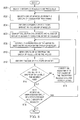
- FIG. 8 an illustration of a flowchart of a process for calibrating an icing simulation system is depicted in accordance with an illustrative embodiment. This process may be used to set icing simulation system 110 to produce drops 132 of water 130 with desired sizes for desired type of icing condition 111 in Figure 1 .
- the process begins by identifying groups of nozzles to be processed (operation 800). The process then selects a group of nozzles from the groups of nozzles for processing (operation 802).
- the process identifies a desired size for drops sprayed by the group of nozzles (operation 804).
- the process identifies values for one or more properties of water to be sent through the group of nozzles (operation 806).
- the properties of the water are controlled to meet those values for the group of nozzles (operation 808).
- Drops of water are then sprayed from the group of nozzles using the values (operation 810).
- the size of the drops of water is identified (operation 812).
- the size of the drops of water may be identified using a sensor system, such as sensor system 123 in Figure 1 .
- a determination is made as to whether the size of the drops of water meet the desired size (operation 814).
- the desired size may be met if the size of the drops of water identified are the same as the desired size. In these illustrative examples, the desired size also may be met, in some cases, if the size of the drops of water are within a range of the desired size.
- this process may be used to calibrate the groups of nozzles prior to simulating a desired type of icing condition, this process may also be used at other times. For example, this process also may be used while the desired type of icing condition is being simulated. The process may be used to adjust the manner in which drops of water are sprayed such that the desired type of icing condition can be maintained even though other parameters in the icing simulation environment may change.
- each block in the flowcharts or block diagrams may represent a module, segment, function, and/or a portion of an operation or step.
- one or more of the blocks may be implemented as program code, in hardware, or a combination of the program code and hardware.
- the hardware may, for example, take the form of integrated circuits that are manufactured or configured to perform one or more operations in the flowcharts or block diagrams.
- the function or functions noted in the blocks may occur out of the order noted in the figures.
- two blocks shown in succession may be executed substantially concurrently, or the blocks may sometimes be performed in the reverse order, depending upon the functionality involved.
- other blocks may be added in addition to the illustrated blocks in a flowchart or block diagram.
- Data processing system 900 may be used to implemented controller 128 in Figure 1 .
- data processing system 900 includes communications framework 902, which provides communications between processor unit 904, memory 906, persistent storage 908, communications unit 910, input/output (I/O) unit 912, and display 914.
- communications framework 902 may take the form of a bus system.
- Processor unit 904 serves to execute instructions for software that may be loaded into memory 906.
- Processor unit 904 may be a number of processors, a multi-processor core, or some other type of processor, depending on the particular implementation.
- Memory 906 and persistent storage 908 are examples of storage devices 916.
- a storage device is any piece of hardware that is capable of storing information, such as, for example, without limitation, data, program code in functional form, and/or other suitable information either on a temporary basis and/or a permanent basis.
- Storage devices 916 may also be referred to as computer readable storage devices in these illustrative examples.
- Memory 906, in these examples, may be, for example, a random access memory or any other suitable volatile or nonvolatile storage device.
- Persistent storage 908 may take various forms, depending on the particular implementation.
- persistent storage 908 may contain one or more components or devices.
- persistent storage 908 may be a hard drive, a flash memory, a rewritable optical disk, a rewritable magnetic tape, or some combination of the above.
- the media used by persistent storage 908 also may be removable.
- a removable hard drive may be used for persistent storage 908.
- Communications unit 910 in these illustrative examples, provides for communications with other data processing systems or devices.
- communications unit 910 is a network interface card.
- Input/output unit 912 allows for input and output of data with other devices that may be connected to data processing system 900.
- input/output unit 912 may provide a connection for user input through a keyboard, a mouse, and/or some other suitable input device. Further, input/output unit 912 may send output to a printer.
- Display 914 provides a mechanism to display information to a user.
- Instructions for the operating system, applications, and/or programs may be located in storage devices 916, which are in communication with processor unit 904 through communications framework 902.
- the processes of the different embodiments may be performed by processor unit 904 using computer-implemented instructions, which may be located in a memory, such as memory 906.
- program code computer usable program code
- computer readable program code that may be read and executed by a processor in processor unit 904.
- the program code in the different embodiments may be embodied on different physical or computer readable storage media, such as memory 906 or persistent storage 908.
- Program code 918 is located in a functional form on computer readable media 920 that is selectively removable and may be loaded onto or transferred to data processing system 900 for execution by processor unit 904.
- Program code 918 and computer readable media 920 form computer program product 922 in these illustrative examples.
- computer readable media 920 may be computer readable storage media 924 or computer readable signal media 926.
- computer readable storage media 924 is a physical or tangible storage device used to store program code 918 rather than a medium that propagates or transmits program code 918.
- program code 918 may be transferred to data processing system 900 using computer readable signal media 926.
- Computer readable signal media 926 may be, for example, a propagated data signal containing program code 918.
- Computer readable signal media 926 may be an electromagnetic signal, an optical signal, and/or any other suitable type of signal. These signals may be transmitted over communications links, such as wireless communications links, optical fiber cable, coaxial cable, a wire, and/or any other suitable type of communications link.
- the different components illustrated for data processing system 900 are not meant to provide architectural limitations to the manner in which different embodiments may be implemented.
- the different illustrative embodiments may be implemented in a data processing system including components in addition to and/or in place of those illustrated for data processing system 900.
- Other components shown in Figure 9 can be varied from the illustrative examples shown.
- the different embodiments may be implemented using any hardware device or system capable of running program code 918.
- aircraft manufacturing and service method 1000 may be described in the context of aircraft manufacturing and service method 1000 as shown in Figure 10 and aircraft 1100 as shown in Figure 11 .
- Figure 10 an illustration of an aircraft manufacturing and service method is depicted in accordance with an illustrative embodiment.
- aircraft manufacturing and service method 1000 may include specification and design 1002 of aircraft 1100 in Figure 11 and material procurement 1004.
- aircraft 1100 During production, component and subassembly manufacturing 1006 and system integration 1008 of aircraft 1100 takes place. Thereafter, aircraft 1100 may go through certification and delivery 1010 in order to be placed in service 1012. While in service 1012 by a customer, aircraft 1100 is scheduled for routine maintenance and service 1014, which may include modification, reconfiguration, refurbishment, and other maintenance or service.
- Each of the processes of aircraft manufacturing and service method 1000 may be performed or carried out by a system integrator, a third party, and/or an operator.
- the operator may be a customer.
- a system integrator may include, without limitation, any number of aircraft manufacturers and major-system subcontractors
- a third party may include, without limitation, any number of vendors, subcontractors, and suppliers
- an operator may be an airline, a leasing company, a military entity, a service organization, and so on.
- aircraft 1100 is produced by aircraft manufacturing and service method 1000 in Figure 10 and may include airframe 1102 with plurality of systems 1104 and interior 1106.
- systems 1104 include one or more of propulsion system 1108, electrical system 1110, hydraulic system 1112, and environmental system 1114. Any number of other systems may be included.
- propulsion system 1108, electrical system 1110, hydraulic system 1112, and environmental system 1114 Any number of other systems may be included.
- an aerospace example is shown, different illustrative embodiments may be applied to other industries, such as the automotive industry.
- Apparatuses and methods embodied herein may be employed during at least one of the stages of aircraft manufacturing and service method 1000 in Figure 10 .
- components or subassemblies produced in component and subassembly manufacturing 1006 in Figure 10 may be fabricated or manufactured in a manner similar to components or subassemblies produced while aircraft 1100 is in service 1012 in Figure 10 .
- one or more apparatus embodiments, method embodiments, or a combination thereof may be utilized during production stages, such as specification and design 1002 and system integration 1008 in Figure 10 .
- icing simulation system 110 may be used to test various prototypes of components or structures during specification and design 1002.
- One or more apparatus embodiments, method embodiments, or a combination thereof may be utilized while aircraft 1100 is in service 1012 and/or during maintenance and service 1014.
- icing simulation system 110 may be used to test upgrades or changes to aircraft 1100 made during maintenance and service 1014. For example, if new or different sensor systems for detecting icing conditions are added to aircraft 1100, icing simulation system 110 may be used to determine whether those sensors perform as desired.
- the use of a number of the different illustrative embodiments may substantially expedite the assembly of and/or reduce the cost of aircraft 1100.
- one or more illustrative embodiments provide a method and apparatus for simulating icing conditions.
- the simulation of the icing conditions may be used to determine whether a test object performs as desired during different types of icing conditions. For example, as requirements change on what types of icing conditions are required to be detected by an aircraft, sensor systems for those types of icing conditions may be designed and tested using an illustrative embodiment.
- icing simulation system 110 provides an ability to generate water drops having different sizes.
- the water drops may have two ranges of sizes. These ranges may be ranges that represent supercooled large drop icing conditions.
- the ranges may be generated by controlling different spray bars within icing simulation system 110 to spray drops of water with different sizes. In this manner, the spray bars may generate drops of water having the two desired ranges of drop sizes for supercooled large drop icing conditions.
- recreating a desired icing condition may reduce the amount of time needed to meet regulations regarding the icing conditions. Further, with the use of icing simulation system 110, the time, effort, and/or expense needed to certify an aircraft or icing detection system may be reduced.
- icing simulation system 110 may be used to generate icing conditions other than those described in the illustrative examples.
- other icing conditions may include three or more ranges of drop sizes.
- an icing simulation system including: a wind tunnel; a nozzle system configured to spray drops of water within the wind tunnel; and a controller configured to control a number of properties of the water in the nozzle system such that the nozzle system sprays the drops of the water with different sizes for a desired type of icing condition.
- the icing simulation system includes wherein the number of properties is selected from at least one of a water pressure, an air pressure, and a temperature.
- the icing simulation system includes wherein the nozzle system comprises groups of nozzles.
- the icing simulation system includes wherein in being configured to control the number of properties of the water in the nozzle system such that the nozzle system sprays the drops of the water with the different sizes for the desired type of icing condition, the controller is configured to select at least one of a water pressure, an air pressure, and a temperature for the water for each group of nozzles in the groups of nozzles such that the groups of nozzles spray the drops of the water with the different sizes for the desired type of icing condition.
- the icing simulation system includes wherein a group of nozzles in the groups of nozzles is associated with a spray bar.
- the icing simulation system further includes: a spray bar balancing system configured to reduce a time for the spray bar to spray the drops of the water with a desired size.
- the icing simulation system further includes: a plurality of valves configured to control at least one of a water pressure, an air pressure, and a temperature for the water; and a computer system configured to control an operation of the plurality of valves.
- the icing simulation system further includes: a sensor system configured to detect a size of the drops of the water.
- the icing simulation system includes wherein the desired type of icing condition is a supercooled large drop icing condition.
- the icing simulation system includes wherein a second type of icing condition includes the drops of the water having a diameter greater than about 0.111 millimeters. In another example, the icing simulation system includes wherein the desired type of icing condition further includes additional drops of the water having a diameter that is less than or equal to about 0.111 millimeters. In yet another example, the icing simulation system includes wherein the wind tunnel includes a test section configured to hold a test object.
- the icing simulation system of claim 12 wherein the test object is selected from one of an airfoil, an aircraft, an engine, a wing, a horizontal stabilizer, a vertical stabilizer, a landing gear system, a fuselage, a flap, an aircraft windshield, an automobile windshield, an automobile, a ship, an engine hood, and a deck of a ship.
- a method for simulating a desired type of icing condition in a wind tunnel, the method including: controlling a number of properties for water sent to a nozzle system, wherein the number of properties is controlled such that drops of the water have different sizes associated with the desired type of icing condition; and spraying the drops of the water from the nozzle system in the wind tunnel, wherein the drops of the water sprayed by the nozzle system have the different sizes for the desired type of icing condition.
- the method includes wherein controlling the number of properties for the water sent to the nozzle system, wherein the number of properties is controlled such that the drops of the water have the different sizes associated with the desired type of icing condition includes: controlling at least one of a water pressure, an air pressure, and a temperature for the water sent to the nozzle system, wherein the number of properties is controlled such that the drops of the water have the different sizes associated with the desired type of icing condition.
- the method includes wherein spraying the drops of the water from the nozzle system in the wind tunnel, wherein the drops of the water sprayed by the nozzle system have the different sizes for the desired type of icing condition includes: spraying the drops of the water from groups of nozzles in the nozzle system in the wind tunnel, wherein the drops of the water sprayed by the nozzle system have the different sizes for the desired type of icing condition.
- the method includes wherein controlling the number of properties for the water sent to the nozzle system, wherein the number of properties is controlled such that the drops of the water have the different sizes associated with the desired type of icing condition includes: selecting at least one of a water pressure, an air pressure, and a temperature for the water for each group of nozzles in the groups of nozzles such that the groups of nozzles spray the drops of the water with the different sizes for the desired type of icing condition.
- the method includes wherein spraying the drops of the water from the groups of nozzles in the nozzle system in the wind tunnel, wherein the drops of the water sprayed by the nozzle system have the different sizes for the desired type of icing condition includes: spraying the drops of the water from the groups of nozzles in the nozzle system in the wind tunnel, wherein the drops of the water sprayed by the nozzle system have the different sizes for the desired type of icing condition, wherein a group of nozzles in the groups of nozzles is associated with a spray bar.
- controlling the number of properties for the water sent to the nozzle system, wherein the number of properties is controlled such that the drops of the water have the different sizes associated with the desired type of icing condition includes: controlling the number of properties for the water sent to the nozzle system, wherein the number of properties is controlled such that the drops of the water have the different sizes associated with a supercooled large drop icing condition.
- the method of further includes: placing a test object in a test section of the wind tunnel, wherein the test object is selected from one an airfoil, an aircraft, an engine, a wing, a horizontal stabilizer, a vertical stabilizer, a landing gear system, a fuselage, a flap, an aircraft windshield, an automobile windshield, an automobile, a ship, an engine hood, and a deck of a ship.
- the test object is selected from one an airfoil, an aircraft, an engine, a wing, a horizontal stabilizer, a vertical stabilizer, a landing gear system, a fuselage, a flap, an aircraft windshield, an automobile windshield, an automobile, a ship, an engine hood, and a deck of a ship.
- the illustrative embodiment may be applied to other types of platforms and structures for those platforms.
- other illustrative embodiments may be applied to a mobile platform, a stationary platform, a land-based structure, an aquatic-based structure, a space-based structure, and/or some other suitable platform or structure for those platforms.
- the different illustrative embodiments may be applied to, for example, without limitation, a submarine, a bus, a personnel carrier, a tank, a train, an automobile, a spacecraft, a space station, a satellite, a surface ship, and/or some other suitable platform.
Landscapes
- Physics & Mathematics (AREA)
- Engineering & Computer Science (AREA)
- Mechanical Engineering (AREA)
- Thermal Sciences (AREA)
- General Engineering & Computer Science (AREA)
- Fluid Mechanics (AREA)
- General Physics & Mathematics (AREA)
- Aerodynamic Tests, Hydrodynamic Tests, Wind Tunnels, And Water Tanks (AREA)
Abstract
Description
- The present disclosure relates generally to icing conditions and, in particular, to simulating icing conditions. Still more particularly, the present disclosure relates to a method and apparatus for simulating icing conditions in which supercooled large drops are present.
- In aviation, icing on an aircraft may occur when the atmospheric conditions lead to the formation of ice on the surfaces of the aircraft. Further, this ice also may occur within the engine. Ice formation on the surfaces of the aircraft, on inlets of an engine, and other locations is undesirable and potentially unsafe for operating the aircraft.
- Icing conditions may occur when drops of supercooled liquid water are present. In these illustrative examples, water is considered to be supercooled when the water is cooled below the stated freezing point for water but the water is still in a liquid form. Icing conditions may be characterized by the size of the drops, the liquid water content, the air temperature, and/or other parameters. These parameters may affect the rate and extent at which ice forms on an aircraft.
- Drops of water may be supercooled in various environments. For example, drops of water may be supercooled in stratiform clouds and in cumulous clouds.
- When icing occurs, the aircraft may not operate as desired. For example, ice on the wing of an aircraft will cause the aircraft to stall at a lower angle of attack and have an increased drag.
- Aircraft may have mechanisms to prevent icing, remove ice, or some combination thereof to handle these icing conditions. For example, aircraft may include icing detection, prevention, and removal systems. Ice may be removed using bleed air, infrared heating, and other suitable mechanisms.
- Aircraft may have sensor systems designed to detect icing conditions. As new regulations are developed with respect to icing conditions that should be detected, manufacturers design and test sensor systems for detecting the icing conditions. For example, aircraft may be required to be certified to operate in normal icing conditions and in supercooled large drop icing conditions.
- In designing and testing sensor systems, currently available test environments may not provide an ability to simulate supercooled large drop icing conditions in the manner desired to test new sensor systems. Therefore, it would be desirable to have a method and apparatus that takes into account at least some of the issues discussed above as well as possibly other issues.
- In one illustrative embodiment, an icing simulation system comprises a wind tunnel, a nozzle system, and a controller. The nozzle system is configured to spray drops of water within the wind tunnel. The controller is configured to control a number of properties of the water in the nozzle system such that the nozzle system sprays the drops of water with different sizes for a desired type of icing condition.
- In another illustrative embodiment, a method for simulating a desired type of icing condition in a wind tunnel is present. A number of properties is controlled for water sent to a nozzle system. The number of properties is controlled such that drops of the water have different sizes associated with the desired type of icing condition. The drops of water are sprayed from the nozzle system in the wind tunnel. The drops of the water sprayed by the nozzle system have different sizes for the desired type of icing condition.
- The features and functions can be achieved independently in various embodiments of the present disclosure or may be combined in yet other embodiments in which further details can be seen with reference to the following description and drawings.
- The novel features believed characteristic of the illustrative embodiments are set forth in the appended claims. The illustrative embodiments, however, as well as a preferred mode of use, further objectives, and features thereof will best be understood by reference to the following detailed description of an illustrative embodiment of the present disclosure when read in conjunction with the accompanying drawings, wherein:
-
Figure 1 is an illustration of a block diagram of an icing simulation environment in accordance with an illustrative embodiment; -
Figure 2 is an illustration of a block diagram of properties controlled by a controller in accordance with an illustrative embodiment; -
Figure 3 is an illustration of a block diagram of a nozzle system in accordance with an illustrative embodiment; -
Figure 4 is an illustration of a block diagram of an infrastructure in an icing simulation system in accordance with an illustrative embodiment; -
Figure 5 is an illustration of an icing simulation system in accordance with an illustrative embodiment; -
Figure 6 is an illustration of a spray bar balancing system in accordance with an illustrative embodiment; -
Figure 7 is an illustration of a flowchart of a process for simulating icing conditions in accordance with an illustrative embodiment; -
Figure 8 is an illustration of a flowchart of a process for calibrating an icing simulation system in accordance with an illustrative embodiment; -
Figure 9 is an illustration of a data processing system in accordance with an illustrative embodiment; -
Figure 10 is an illustration of an aircraft manufacturing and service method in accordance with an illustrative embodiment; and -
Figure 11 is an illustration of an aircraft in which an illustrative embodiment may be implemented. - The illustrative embodiments recognize and take into account one or more different considerations. For example, the illustrative embodiments recognize and take into account that currently available systems for simulating icing conditions are unable to simulate supercooled large drop icing conditions. In particular, the illustrative embodiments recognize and take into account that simulating this type of icing condition involves generating drops of water having two ranges of sizes. These ranges may be two different distributions of water drop sizes. This type of distribution may take the form of a supercooled large drop bimodal distribution.
- For example, the illustrative embodiments recognize and take into account that currently available wind tunnels used to simulate icing conditions are unable to generate drops of water having the two ranges of sizes for supercooled large drop icing conditions.
- Thus, one or more illustrative embodiments provide a method and apparatus for simulating icing conditions. In one illustrative embodiment, an icing simulation system comprises a wind tunnel, a nozzle system, and a controller. The nozzle system is configured to spray drops of water within the wind tunnel. The controller is configured to control a number of properties of the water in the nozzle system such that the nozzle system sprays the drops of water with different sizes for a desired type of icing condition.
- With reference now to the figures and, in particular, with reference to
Figure 1 , an illustration of a block diagram of an icing simulation environment is depicted in accordance with an illustrative embodiment. In this illustrative example,icing simulation environment 100 may be used to simulate types oficing conditions 102. - In particular, types of
icing conditions 102 may be simulated fortest object 103.Test object 103 may be, for example,structure 104,platform 106, or both.Structure 104 may be a structure inplatform 106. Whenplatform 106 takes the form ofaircraft 108,structure 104 may be a structure inaircraft 108. For example,structure 104 may be a wing, a horizontal stabilizer, a vertical stabilizer, an engine, a landing gear system, a fuselage, a flap, an aircraft windshield, or some other suitable structure. - In one illustrative embodiment,
icing simulation system 110 may be used to simulate desired type oficing condition 111 in one or more of types oficing conditions 102 fortest object 103. Desired type oficing condition 111 is a type of icing condition for which testing is desired with respect to testobject 103. - In particular, icing
simulation system 110 may be used to simulate desired type oficing condition 111 as first type oficing condition 112, second type oficing condition 114, or both. - In these illustrative examples, first type of
icing condition 112 and second type oficing condition 114 in types oficing conditions 102 may differ from each other based on drop size. The drop size may differ based on a mean volumetric diameter. More specifically, the drop sizes may differ based on ranges of sizes. In other words, first type oficing condition 112 may have one range of sizes, and second type oficing condition 114 may have another range of sizes. The distribution of sizes within the ranges also may be used to define different types of icing conditions. - In these illustrative examples, first type of
icing condition 112 may be present when the size of the drops is from about 0.00465 millimeters in diameter to about 0.111 millimeters in diameter. Drops with these sizes may be referred to as normal drops. - Second type of
icing condition 114 may be present when the size of the drops includes drops that have a diameter greater than about 0.111 millimeters. Drops having a size greater than about 0.111 millimeters may be referred to as large drops and, in particular, may be called supercooled large drops under the altitude, temperature, and liquid water content conditions described above. For example, the drops may have a diameter in a range from about 0.112 millimeters to about 2.2 millimeters. In addition, second type oficing condition 114 may include drops that are 0.111 millimeters or less when drops greater than 0.111 millimeters are present. In other words, second type oficing condition 114 includes both normal drops and large drops of water. - In simulating desired type of
icing condition 111, liquid water content in the drops may also be used to characterize the type of icing condition. For example, first type oficing condition 112 may have liquid water content in the range of about 0.04 grams per cubic meter to about 2.8 grams per cubic meter. On the other hand, second type oficing condition 114 may have liquid water content in the range of about 0.19 grams per cubic meter to about 0.44 grams per cubic meter. - In the depicted examples, icing
simulation system 110 is a physical system that also may include software.Icing simulation system 110 includeswind tunnel 116,air drive system 118,cooling system 120,nozzle system 122,sensor system 123,water source 124,air source 126,infrastructure 127,controller 128, and other suitable components. - As depicted,
air drive system 118 causesair 129 to flow withinwind tunnel 116.Cooling system 120 may cool the temperature ofair 129 withinwind tunnel 116. -
Infrastructure 127 comprises components that carrywater 130 andair 134 tonozzle system 122. In particular,infrastructure 127 connectswater source 124 andair source 126 tonozzle system 122. Additionally,infrastructure 127 also may be connected to coolingsystem 120. The connection to coolingsystem 120 may be used tocool water 130,air 134, or both. Additionally,infrastructure 127 also may be connected to coolingsystem 120. The connection to coolingsystem 120 may be used tocool water 130,air 134, or both. -
Nozzle system 122 receiveswater 130 fromwater source 124 throughinfrastructure 127 and generatesdrops 132 ofwater 130. In other words, drops 132 ofwater 130 are generated bywater 130 flowing throughnozzle system 122. - In some illustrative examples,
air 134 received throughinfrastructure 127 may be introduced intowater 130 aswater 130 flows throughnozzle system 122 to form drops 132 ofwater 130. In these illustrative examples,air source 126 also may sendair 134 tonozzle system 122 viainfrastructure 127. Withinnozzle system 122,air 134 may be mixed withwater 130 to form drops 132 ofwater 130 sprayed bynozzle system 122. - In these illustrative examples, drops 132 of
water 130 generated bynozzle system 122 may haveproperties 136 to simulate first type oficing condition 112, second type oficing condition 114, or both. In these illustrative examples,properties 136 ofdrops 132 ofwater 130 may include, for example, without limitation, size, water content, temperature, and other suitable properties. -
Sensor system 123 is configured to generate data about one or more ofproperties 136 ofdrops 132 ofwater 130. In other words,sensor system 123 identifiesproperties 136 ofdrops 132 ofwater 130 generated bynozzle system 122 withinwind tunnel 116. -
Controller 128 is configured to controlproperties 140 ofwater 130 to simulate at least one of first type oficing condition 112, second type oficing condition 114, or both. -
Controller 128 may use data fromsensor system 123 to adjust values for a number of properties inproperties 140 ofwater 130 to obtain desired type oficing condition 111 within types oficing conditions 102. In other words,sensor system 123 provides feedback tocontroller 128 aboutdrops 132 ofwater 130. The data received fromsensor system 123 may be used to adjustproperties 140 ofwater 130 ifproperties 136 fordrops 132 ofwater 130 do not have desired values for desired type oficing condition 111. - The adjustment of
properties 140 ofwater 130 made bycontroller 128 may be made at different times during testing. For example, the adjustment may be made prior to placingtest object 103 intowind tunnel 116 for testing of desired type oficing condition 111. Additionally, these adjustments may be made while the simulation of desired type oficing condition 111 is performed ontest object 103. In other words, adjustments may be made dynamically during the testing to maintain desired type oficing condition 111. - In these illustrative examples,
controller 128 is comprised of hardware, software, or both. For example,controller 128 may be a computer system. The computer system may include one or more computers. When more than one computer is present in the computer system, those computers may be in communication with each other through a network. In other illustrative examples,controller 128 may be implemented using hardware with circuits configured to perform operations to simulate types oficing conditions 102. - In these illustrative examples, the hardware may take the form of a circuit system, an integrated circuit, an application specific integrated circuit (ASIC), a programmable logic device, or some other suitable type of hardware configured to perform a number of operations. With a programmable logic device, the device is configured to perform the number of operations. The device may be reconfigured at a later time or may be permanently configured to perform the number of operations. Examples of programmable logic devices include, for example, a programmable logic array, a programmable array logic, a field programmable logic array, a field programmable gate array, and other suitable hardware devices. Additionally, the processes may be implemented in organic components integrated with inorganic components and/or may be comprised entirely of organic components excluding a human being.
- As depicted,
test object 103 may be placed intest area 142 inwind tunnel 116 for exposure todrops 132 ofwater 130. By controllingproperties 140 forwater 130, drops 132 ofwater 130 may be generated byproperties 136 to simulate desired type oficing condition 111. - This simulation of desired type of
icing condition 111 may be used to determine howtest object 103 may function. For example,test object 103 may be an airfoil with sensors configured to detect icing conditions. By simulating desired type oficing condition 111, a determination may be made as to whether the sensors are able to detect desired type oficing condition 111. In these illustrative examples, desired type oficing condition 111 may be a supercooled large drop icing condition. - Turning now to
Figure 2 , an illustration of a block diagram of properties controlled by a controller is depicted in accordance with an illustrative embodiment. Examples ofproperties 140 ofwater 130 that may be controlled bycontroller 128 to obtainproperties 136 fordrops 132 to simulate desired type oficing condition 111 in types oficing conditions 102 inFigure 1 are shown in this illustrative example. - In these illustrative examples,
properties 140 include at least one ofwater pressure 202,air pressure 204,air flow 206,temperature 208, and other suitable properties.Properties 140 controlled bycontroller 128 may be selected from one or more ofproperties 140. -
Water pressure 202 is the pressure ofwater 130 innozzle system 122 inFigure 1 .Air pressure 204 is the pressure ofair 134 introduced intonozzle system 122.Air flow 206 is the speed at which air moves withinwind tunnel 116.Temperature 208 is the temperature ofwater 130 innozzle system 122.Temperature 208 may be selected to be near or below freezing forwater 130 prior towater 130 being sprayed asdrops 132 fromnozzle system 122. The selection oftemperature 208 is such thatwater 130 does not freeze within nozzles innozzle system 122. - In these illustrative examples, values for at least one of
water pressure 202,air pressure 204, andair flow 206 ofproperties 140 may be selected to obtainproperties 136 ofdrops 132 that are desired for desired type oficing condition 111. These properties may include at least one of, for example, without limitation, size, water content, temperature, and other suitable properties fordrops 132 ofwater 130 in a manner that produces desired type oficing condition 111 in types oficing conditions 102. - The values for
properties 140 may change, depending on the particular type of icing condition in types oficing conditions 102. In other words, the values ofproperties 140 selected for first type oficing condition 112 are different from the values ofproperties 140 selected for second type oficing condition 114. - For example,
air pressure 204 may be from about 10 psi to about 60 psi, andwater pressure 202 may be from about 20 psi to about 240 psi. This combination ofair pressure 204 andwater pressure 202 may produce water drops having sizes of up to about 0.050 millimeters. The size of the water drops may be increased by changing the pressure of the water relative to the pressure of the air. - For example,
air pressure 204 may be changed by a magnitude relative towater pressure 202. For example,water pressure 202 may be about 80 psi, andair pressure 204 may be about 8 psi. With this setting, the drops of water may be about 0.500 millimeters. - In some illustrative examples,
air pressure 204 may be from about 10 psi to about 60 psi.Water pressure 202 may be from about 10 psi to about 240 psi. Of course, the values ofwater pressure 202 andair pressure 204 may change, depending on the types of nozzles used. - With reference now to
Figure 3 , an illustration of a block diagram of a nozzle system is depicted in accordance with an illustrative embodiment. Examples of components fornozzle system 122 are illustrated in this figure. - As depicted,
nozzle system 122 is comprised of groups ofnozzles 300 andsupport structures 301. In these illustrative examples, a group of nozzles within groups ofnozzles 300 includes one or more nozzles. Further, one group of nozzles within groups ofnozzles 300 may have a different number of nozzles than another group of nozzles within groups ofnozzles 300. -
Support structures 301 are configured to be associated with groups ofnozzles 300. When one component is "associated" with another component, the association is a physical association in these depicted examples. For example, a first component, group ofnozzles 304 in groups ofnozzles 300, may be considered to be associated with a second component,support structure 306 insupport structures 301, by being secured to the second component, bonded to the second component, mounted to the second component, welded to the second component, fastened to the second component, and/or connected to the second component in some other suitable manner. The first component also may be connected to the second component using a third component. The first component may also be considered to be associated with the second component by being formed as part of and/or an extension of the second component. Further, the association may be a temporary association in which the first component may be removed from the second component or vice versa. -
Support structures 301 may also be configured to receive water and direct water to groups ofnozzles 300. In these illustrative examples,support structures 301 may include lines, valves, or other components that may be used to control the flow of water withinsupport structures 301. In some illustrative examples,support structures 301 also may include sensors used to generate data about water flowing throughsupport structures 301. - As depicted, the association of groups of
nozzles 300 withsupport structures 301 forms plurality of spray bars 302. Each group of nozzles in groups ofnozzles 300 is associated with a support structure insupport structures 301. For example, the association of group ofnozzles 304 withsupport structure 306 forms spraybar 308. - In these illustrative examples,
properties 140 inFigure 2 may be controlled with different levels of granularity. For example, each group of nozzles in groups ofnozzles 300 may have different values forproperties 140 as compared to other groups of nozzles. - In still other illustrative examples, when more than one nozzle is in group of
nozzles 304, values forproperties 140 may be controlled individually for each nozzle in group ofnozzles 304. In other words, one group of nozzles in groups ofnozzles 300 may spray drops 132 ofwater 130 inFigure 1 with a different size or range of sizes as compared to another group of nozzles in groups ofnozzles 300 through the control ofproperties 140 for these two groups of nozzles. In this manner, the sizes ofdrops 132 ofwater 130 may be achieved using groups ofnozzles 300 to obtain a desired type of icing condition within types oficing conditions 102 inFigure 1 . - Turning now to
Figure 4 , an illustration of a block diagram of an infrastructure in an icing simulation system is depicted in accordance with an illustrative embodiment. In this illustrative example, examples of some components that may be present ininfrastructure 127 includelines 400,valves 402, andsensors 403 are shown.Lines 400 may include, for example,flexible lines 404 andrigid lines 406. - In these illustrative examples,
lines 400 may be used to connectwater source 124 andair source 126 tonozzle system 122 inFigure 1 . Further, some oflines 400 may be connected to coolingsystem 120 inFigure 1 . -
Valves 402 are associated withlines 400.Valves 402 may be operated to control the flow of fluids throughlines 400. In these illustrative examples, these fluids may bewater 130 andair 134 inFigure 1 . In these illustrative examples, the operation ofvalves 402 is controlled bycontroller 128.Controller 128 operatesvalves 402 to select values forproperties 140 inFigure 1 . -
Sensors 403 are configured to detect the values ofproperties 140. Additionally,sensors 403 also may be configured to detect the position ofvalves 402, the flow of liquids throughlines 400, and other suitable parameters. - As depicted,
sensors 403 may be associated withlines 400 andvalves 402. Further,sensors 403 also may be associated withnozzle system 122. -
Sensors 403 generatedata 408 that is sent tocontroller 128.Controller 128 operatesvalves 402 to adjust the values ofproperties 140. - The illustration of icing
simulation environment 100 inFigure 1 and the components oficing simulation environment 100 inFigures 1-4 are not meant to imply physical or architectural limitations to the manner in which an illustrative embodiment may be implemented. Other components in addition to or in place of the ones illustrated may be used. Some components may be unnecessary. Also, the blocks are presented to illustrate some functional components. One or more of these blocks may be combined, divided, or combined and divided into different blocks when implemented in an illustrative embodiment. - In some illustrative examples, one or more test objects in addition to
test object 103 may be placed intest area 142 during simulation of desired type oficing condition 111 usingicing simulation system 110. Also,test object 103 may take other forms other than an aircraft or objects that are for or part of an aircraft. For example,test object 103 may be selected from one of an automobile windshield, automobile, a ship, an engine hood, a deck of a ship, and other suitable test objects. - In still other illustrative examples,
valves 402,sensors 403, or both may be considered part ofcontroller 128. In still other illustrative examples, additional types of icing conditions in addition to or in place of first type oficing condition 112 and second type oficing condition 114 in types oficing conditions 102 may be present. For example, in some types of icing conditions, three or more ranges of sizes fordrops 132 ofwater 130 may be present for those types of icing conditions. - Turning now to
Figure 5 , an illustration of an icing simulation system is depicted in accordance with an illustrative embodiment. In this depicted example, icingsimulation system 500 is one example of a physical implementation foricing simulation system 110 shown in block form inFigure 1 . - In this illustrative example, a top view of
icing simulation system 500 is shown. As depicted,icing simulation system 500 includeswind tunnel 502,air drive system 504,nozzle system 506,cooling system 508, andcontroller 510. - In this depicted example,
wind tunnel 502 has turningvane 512, turningvane 514, turningvane 516, and turningvane 518. These turning vanes aid in directingair flow 520 generated byair drive system 504 to turn or curve withinwind tunnel 502. - As depicted,
air flow 520 is generated byair drive system 504. In this illustrative example,air drive system 504 comprisesfan system 522. In this illustrative example,nozzle system 506 comprises spray bars 524. - In these illustrative examples, spray bars 524 are configured to spray drops of
water 526 withinwind tunnel 502. Drops ofwater 526 are carried byair flow 520 throughtest section 528 withinwind tunnel 502. - In these illustrative examples,
air flow 520 is cooled usingcooling system 508. As depicted,cooling system 508 comprisesrefrigeration system 530 andheat exchanger 532.Refrigeration system 530 andheat exchanger 532 operate to cool air withinair flow 520 passing by or throughheat exchanger 532. - In this illustrative example,
sensor system 509 takes the form oflaser sensor system 534.Laser sensor system 534 sendslaser beam 536 intowind tunnel 502 where drops ofwater 526 are generated byspray bars 524 innozzle system 506.Laser sensor system 534 sends data about sizes of drops ofwater 526 tocontroller 510 incontrol room 538. - With feedback from
laser sensor system 534 insensor system 509,controller 510 may adjust properties of water sent throughspray bars 524 innozzle system 506 to obtain desired sizes for drops ofwater 526 to simulate a desired type of icing condition. - In these illustrative examples, drops of
water 526 may have two ranges of sizes for the desired icing condition. In particular, the desired icing condition may be a supercooled large drop icing condition. In these illustrative examples, drops ofwater 526 may include sizes for normal drops and sizes for supercooled large drops. - Turning now to
Figure 6 , an illustration of a spray bar balancing system is depicted in accordance with an illustrative embodiment. As depicted, spraybar balancing system 600 may be implemented in a number of different places withinicing simulation system 110 inFigure 1 . For example, spraybar balancing system 600 may be implemented as part ofinfrastructure 127,nozzle system 122, or a combination of the two inFigure 1 . - In this illustrative example, spray
bar balancing system 600 may be used to controlspray bar 602 in a manner that allows fordrops 604 of water to be produced with a desired size and temperature more quickly to form a desired icing cloud for a desired type of icing condition. - As described above, the drop size may be defined by the mean volumetric diameter of the drops of water and/or the liquid water content in the drops of water. These parameters are functions of the pressure of air in
spray bar 602 and the change in pressure of air inspray bar 602, as well as the velocity of the drops of water within the tunnel. - In this illustrative example,
spray bar 602 is comprised ofsupport structure 605 andnozzles 606. In this example,nozzles 606 includenozzle 608,nozzle 610,nozzle 612, andnozzle 614.Support structure 605 containswater line 618 andair line 620.Water line 618 supplies water tonozzles 606, andair line 620 supplies air tonozzles 606. - In these illustrative examples,
valves 622 insupport structure 605 control water that passes throughnozzles 606. As depicted,valves 622 includevalve 624,valve 626,valve 628, andvalve 630. These valves are associated withnozzle 608,nozzle 610,nozzle 612, andnozzle 614, respectively. - In these illustrative examples,
support structure 605 inspray bar 602 haswater input 632 andwater return output 634. Additionally,support structure 605 hasair input 636.Water input 632 is connected towater supply 638 byline 640.Water return output 634 is connected towater return 642 byline 644.Air input 636 is connected toair supply 646 byline 648.Needle valve 650 andbypass valve 652 are associated withline 644.Air valve 654 is associated withline 648.Pressure valve 656 is associated withline 640. - In this illustrative example,
spray bar 602 may operate in a spray mode and a bypass mode. In bypass mode,spray bar 602 does not spray drops 604 of water. In this mode,valves 622 are closed andbypass valve 652 is open. In this manner, water flowing fromwater supply 638 may flow throughwater line 618 insupport structure 605 ofspray bar 602. This water may flow out ofspray bar 602 atwater return output 634 and throughline 644 towater return 642. - When in the bypass mode,
pressure valve 656 may be adjusted to supply water at a desired pressure level for a desired type of icing condition. In this manner, the desired pressure may be present before switching to a spray mode. - When
spray bar 602 is placed into a spray mode,valves 622 are opened, andbypass valve 652 is closed. In the spray mode, drops 604 of water are sprayed out ofnozzles 606 fromspray bar 602.Drops 604 of water form an icing cloud in these illustrative examples.Drops 604 of water have properties that simulate a desired icing condition. - In spray mode,
valves 622 are open to allowdrops 604 of water to be sprayed out ofnozzles 606. Additionally,air valve 654 andpressure valve 656 are also open.Bypass valve 652 is closed. - With
air valve 654 open, air may flow fromair supply 646 throughline 648 intoair line 620 throughair input 636 to reachnozzles 606. Additionally, water may flow fromwater supply 638 throughline 640 intowater input 632 to reachnozzles 606. - In these illustrative examples, this operation of the valves may cause a change in the pressure of the water flowing to
nozzles 606.Needle valve 650 is located downstream ofbypass valve 652 and is configured to balance the flow of water during the change from a bypass mode to a spray mode. In this manner, any change in the pressure of the water may be reduced such that the change does not affect the spraying ofdrops 604 of water in a manner that affects simulating the desired icing condition. In other words, the properties ofdrops 604 of water may reach desired properties for the desired icing condition more quickly with this configuration. - The different components shown in
Figures 5-6 may be combined with components inFigures 1-4 , used with components inFigures 1-4 , or a combination of the two. Additionally, some of the components inFigures 5-6 may be illustrative examples of how components shown in block form inFigures 1-4 can be implemented as physical structures. - With reference now to
Figure 7 , an illustration of a flowchart of a process for simulating icing conditions is depicted in accordance with an illustrative embodiment. The process illustrated inFigure 7 may be implemented in icingsimulation environment 100 inFigure 1 . In particular, the process may be implemented inicing simulation system 110. - The process begins by identifying a desired type of icing condition (operation 700). The process identifies a number of properties for water sent to a nozzle system for the desired type of icing condition (operation 702).
- Next, a test object is placed into a wind tunnel (operation 704). A number of properties for the water sent to the nozzle system is controlled (operation 706). In these illustrative examples, the number of properties is controlled such that drops of water have sizes associated with the type of icing condition. In other words, the values for the properties are selected such that drops of water have sizes that are characteristic of the type of icing condition to be simulated.
- For example, with a supercooled large drop icing condition, the drops of water may include normal drops and large drops as described above. Further, the water also may have a desired temperature that can be reached as the drops of water travel in the wind tunnel.
- Drops of water are then sprayed from the nozzle system in the wind tunnel (operation 708), with the process terminating thereafter. The drops of water sprayed by the nozzle system have different sizes that correspond to the desired type of icing condition. These different sizes may be different ranges, depending on the type of icing condition.
- In this manner, the simulation of the icing condition in a wind tunnel allows for a test object to be tested to see how the test object performs in the desired icing condition. For example, sensor systems for detecting icing conditions may be tested using this process without placing the sensors on an aircraft and flying the aircraft into weather with the desired icing condition.
- With reference now to
Figure 8 , an illustration of a flowchart of a process for calibrating an icing simulation system is depicted in accordance with an illustrative embodiment. This process may be used to seticing simulation system 110 to producedrops 132 ofwater 130 with desired sizes for desired type oficing condition 111 inFigure 1 . - The process begins by identifying groups of nozzles to be processed (operation 800). The process then selects a group of nozzles from the groups of nozzles for processing (operation 802).
- The process identifies a desired size for drops sprayed by the group of nozzles (operation 804). Next, the process identifies values for one or more properties of water to be sent through the group of nozzles (operation 806). The properties of the water are controlled to meet those values for the group of nozzles (operation 808). Drops of water are then sprayed from the group of nozzles using the values (operation 810).
- Next, the size of the drops of water is identified (operation 812). The size of the drops of water may be identified using a sensor system, such as
sensor system 123 inFigure 1 . A determination is made as to whether the size of the drops of water meet the desired size (operation 814). The desired size may be met if the size of the drops of water identified are the same as the desired size. In these illustrative examples, the desired size also may be met, in some cases, if the size of the drops of water are within a range of the desired size. - If the size of the drops of water does not meet the desired size, an adjustment to the values of the properties needed to reach the desired size is identified (operation 816). The process then returns to
operation 808. - With reference again to
operation 814, if the desired size of the drops of water is met, a determination is made as to whether an additional unprocessed group of nozzles is present in the groups of nozzles (operation 818). If an additional unprocessed group of nozzles is present, the process returns tooperation 802. Otherwise, the process terminates. - Although this process may be used to calibrate the groups of nozzles prior to simulating a desired type of icing condition, this process may also be used at other times. For example, this process also may be used while the desired type of icing condition is being simulated. The process may be used to adjust the manner in which drops of water are sprayed such that the desired type of icing condition can be maintained even though other parameters in the icing simulation environment may change.
- The flowcharts and block diagrams in the different depicted embodiments illustrate the architecture, functionality, and operation of some possible implementations of apparatuses and methods in an illustrative embodiment. In this regard, each block in the flowcharts or block diagrams may represent a module, segment, function, and/or a portion of an operation or step. For example, one or more of the blocks may be implemented as program code, in hardware, or a combination of the program code and hardware. When implemented in hardware, the hardware may, for example, take the form of integrated circuits that are manufactured or configured to perform one or more operations in the flowcharts or block diagrams.
- In some alternative implementations of an illustrative embodiment, the function or functions noted in the blocks may occur out of the order noted in the figures. For example, in some cases, two blocks shown in succession may be executed substantially concurrently, or the blocks may sometimes be performed in the reverse order, depending upon the functionality involved. Also, other blocks may be added in addition to the illustrated blocks in a flowchart or block diagram.
- Turning now to
Figure 9 , an illustration of a data processing system is depicted in accordance with an illustrative embodiment.Data processing system 900 may be used to implementedcontroller 128 inFigure 1 . In this illustrative example,data processing system 900 includescommunications framework 902, which provides communications betweenprocessor unit 904,memory 906,persistent storage 908,communications unit 910, input/output (I/O)unit 912, anddisplay 914. In this example,communications framework 902 may take the form of a bus system. -
Processor unit 904 serves to execute instructions for software that may be loaded intomemory 906.Processor unit 904 may be a number of processors, a multi-processor core, or some other type of processor, depending on the particular implementation. -
Memory 906 andpersistent storage 908 are examples ofstorage devices 916. A storage device is any piece of hardware that is capable of storing information, such as, for example, without limitation, data, program code in functional form, and/or other suitable information either on a temporary basis and/or a permanent basis.Storage devices 916 may also be referred to as computer readable storage devices in these illustrative examples.Memory 906, in these examples, may be, for example, a random access memory or any other suitable volatile or nonvolatile storage device.Persistent storage 908 may take various forms, depending on the particular implementation. - For example,
persistent storage 908 may contain one or more components or devices. For example,persistent storage 908 may be a hard drive, a flash memory, a rewritable optical disk, a rewritable magnetic tape, or some combination of the above. The media used bypersistent storage 908 also may be removable. For example, a removable hard drive may be used forpersistent storage 908. -
Communications unit 910, in these illustrative examples, provides for communications with other data processing systems or devices. In these illustrative examples,communications unit 910 is a network interface card. - Input/
output unit 912 allows for input and output of data with other devices that may be connected todata processing system 900. For example, input/output unit 912 may provide a connection for user input through a keyboard, a mouse, and/or some other suitable input device. Further, input/output unit 912 may send output to a printer.Display 914 provides a mechanism to display information to a user. - Instructions for the operating system, applications, and/or programs may be located in
storage devices 916, which are in communication withprocessor unit 904 throughcommunications framework 902. The processes of the different embodiments may be performed byprocessor unit 904 using computer-implemented instructions, which may be located in a memory, such asmemory 906. - These instructions are referred to as program code, computer usable program code, or computer readable program code that may be read and executed by a processor in
processor unit 904. The program code in the different embodiments may be embodied on different physical or computer readable storage media, such asmemory 906 orpersistent storage 908. -
Program code 918 is located in a functional form on computerreadable media 920 that is selectively removable and may be loaded onto or transferred todata processing system 900 for execution byprocessor unit 904.Program code 918 and computerreadable media 920 formcomputer program product 922 in these illustrative examples. In one example, computerreadable media 920 may be computerreadable storage media 924 or computerreadable signal media 926. - In these illustrative examples, computer
readable storage media 924 is a physical or tangible storage device used to storeprogram code 918 rather than a medium that propagates or transmitsprogram code 918. - Alternatively,
program code 918 may be transferred todata processing system 900 using computerreadable signal media 926. Computerreadable signal media 926 may be, for example, a propagated data signal containingprogram code 918. For example, computerreadable signal media 926 may be an electromagnetic signal, an optical signal, and/or any other suitable type of signal. These signals may be transmitted over communications links, such as wireless communications links, optical fiber cable, coaxial cable, a wire, and/or any other suitable type of communications link. - The different components illustrated for
data processing system 900 are not meant to provide architectural limitations to the manner in which different embodiments may be implemented. The different illustrative embodiments may be implemented in a data processing system including components in addition to and/or in place of those illustrated fordata processing system 900. Other components shown inFigure 9 can be varied from the illustrative examples shown. The different embodiments may be implemented using any hardware device or system capable of runningprogram code 918. - Illustrative embodiments of the disclosure may be described in the context of aircraft manufacturing and
service method 1000 as shown inFigure 10 andaircraft 1100 as shown inFigure 11 . Turning first toFigure 10 , an illustration of an aircraft manufacturing and service method is depicted in accordance with an illustrative embodiment. During pre-production, aircraft manufacturing andservice method 1000 may include specification anddesign 1002 ofaircraft 1100 inFigure 11 andmaterial procurement 1004. - During production, component and
subassembly manufacturing 1006 andsystem integration 1008 ofaircraft 1100 takes place. Thereafter,aircraft 1100 may go through certification anddelivery 1010 in order to be placed inservice 1012. While inservice 1012 by a customer,aircraft 1100 is scheduled for routine maintenance andservice 1014, which may include modification, reconfiguration, refurbishment, and other maintenance or service. - Each of the processes of aircraft manufacturing and
service method 1000 may be performed or carried out by a system integrator, a third party, and/or an operator. In these examples, the operator may be a customer. For the purposes of this description, a system integrator may include, without limitation, any number of aircraft manufacturers and major-system subcontractors; a third party may include, without limitation, any number of vendors, subcontractors, and suppliers; and an operator may be an airline, a leasing company, a military entity, a service organization, and so on. - With reference now to
Figure 11 , an illustration of an aircraft is depicted in which an illustrative embodiment may be implemented. In this example,aircraft 1100 is produced by aircraft manufacturing andservice method 1000 inFigure 10 and may includeairframe 1102 with plurality ofsystems 1104 and interior 1106. Examples ofsystems 1104 include one or more ofpropulsion system 1108,electrical system 1110,hydraulic system 1112, andenvironmental system 1114. Any number of other systems may be included. Although an aerospace example is shown, different illustrative embodiments may be applied to other industries, such as the automotive industry. - Apparatuses and methods embodied herein may be employed during at least one of the stages of aircraft manufacturing and
service method 1000 inFigure 10 . In one illustrative example, components or subassemblies produced in component andsubassembly manufacturing 1006 inFigure 10 may be fabricated or manufactured in a manner similar to components or subassemblies produced whileaircraft 1100 is inservice 1012 inFigure 10 . - As yet another example, one or more apparatus embodiments, method embodiments, or a combination thereof may be utilized during production stages, such as specification and
design 1002 andsystem integration 1008 inFigure 10 . For example, icingsimulation system 110 may be used to test various prototypes of components or structures during specification anddesign 1002. - One or more apparatus embodiments, method embodiments, or a combination thereof may be utilized while
aircraft 1100 is inservice 1012 and/or during maintenance andservice 1014. For example, icingsimulation system 110 may be used to test upgrades or changes toaircraft 1100 made during maintenance andservice 1014. For example, if new or different sensor systems for detecting icing conditions are added toaircraft 1100, icingsimulation system 110 may be used to determine whether those sensors perform as desired. The use of a number of the different illustrative embodiments may substantially expedite the assembly of and/or reduce the cost ofaircraft 1100. - Thus, one or more illustrative embodiments provide a method and apparatus for simulating icing conditions. The simulation of the icing conditions may be used to determine whether a test object performs as desired during different types of icing conditions. For example, as requirements change on what types of icing conditions are required to be detected by an aircraft, sensor systems for those types of icing conditions may be designed and tested using an illustrative embodiment.
- For example, icing
simulation system 110 provides an ability to generate water drops having different sizes. In particular, the water drops may have two ranges of sizes. These ranges may be ranges that represent supercooled large drop icing conditions. The ranges may be generated by controlling different spray bars withinicing simulation system 110 to spray drops of water with different sizes. In this manner, the spray bars may generate drops of water having the two desired ranges of drop sizes for supercooled large drop icing conditions. - With icing
simulation system 110, recreating a desired icing condition may reduce the amount of time needed to meet regulations regarding the icing conditions. Further, with the use oficing simulation system 110, the time, effort, and/or expense needed to certify an aircraft or icing detection system may be reduced. - Of course, icing
simulation system 110 may be used to generate icing conditions other than those described in the illustrative examples. For example, other icing conditions may include three or more ranges of drop sizes. - In the text and the figures, in one aspect, an icing simulation system is disclosed including: a wind tunnel; a nozzle system configured to spray drops of water within the wind tunnel; and a controller configured to control a number of properties of the water in the nozzle system such that the nozzle system sprays the drops of the water with different sizes for a desired type of icing condition. In one variant, the icing simulation system includes wherein the number of properties is selected from at least one of a water pressure, an air pressure, and a temperature. In another variant, the icing simulation system includes wherein the nozzle system comprises groups of nozzles.
- In yet another variant, the icing simulation system includes wherein in being configured to control the number of properties of the water in the nozzle system such that the nozzle system sprays the drops of the water with the different sizes for the desired type of icing condition, the controller is configured to select at least one of a water pressure, an air pressure, and a temperature for the water for each group of nozzles in the groups of nozzles such that the groups of nozzles spray the drops of the water with the different sizes for the desired type of icing condition. In still another variant, the icing simulation system includes wherein a group of nozzles in the groups of nozzles is associated with a spray bar.
- In one instance, the icing simulation system further includes: a spray bar balancing system configured to reduce a time for the spray bar to spray the drops of the water with a desired size.
- In another instance, the icing simulation system further includes: a plurality of valves configured to control at least one of a water pressure, an air pressure, and a temperature for the water; and a computer system configured to control an operation of the plurality of valves. In yet another instance, the icing simulation system further includes: a sensor system configured to detect a size of the drops of the water. In still yet another instance, the icing simulation system includes wherein the desired type of icing condition is a supercooled large drop icing condition.
- In one example, the icing simulation system includes wherein a second type of icing condition includes the drops of the water having a diameter greater than about 0.111 millimeters. In another example, the icing simulation system includes wherein the desired type of icing condition further includes additional drops of the water having a diameter that is less than or equal to about 0.111 millimeters. In yet another example, the icing simulation system includes wherein the wind tunnel includes a test section configured to hold a test object. In still yet another example, the icing simulation system of claim 12, wherein the test object is selected from one of an airfoil, an aircraft, an engine, a wing, a horizontal stabilizer, a vertical stabilizer, a landing gear system, a fuselage, a flap, an aircraft windshield, an automobile windshield, an automobile, a ship, an engine hood, and a deck of a ship.
- In one aspect, a method is disclosed for simulating a desired type of icing condition in a wind tunnel, the method including: controlling a number of properties for water sent to a nozzle system, wherein the number of properties is controlled such that drops of the water have different sizes associated with the desired type of icing condition; and spraying the drops of the water from the nozzle system in the wind tunnel, wherein the drops of the water sprayed by the nozzle system have the different sizes for the desired type of icing condition. In one variant, the method includes wherein controlling the number of properties for the water sent to the nozzle system, wherein the number of properties is controlled such that the drops of the water have the different sizes associated with the desired type of icing condition includes: controlling at least one of a water pressure, an air pressure, and a temperature for the water sent to the nozzle system, wherein the number of properties is controlled such that the drops of the water have the different sizes associated with the desired type of icing condition.
- In another variant, the method includes wherein spraying the drops of the water from the nozzle system in the wind tunnel, wherein the drops of the water sprayed by the nozzle system have the different sizes for the desired type of icing condition includes: spraying the drops of the water from groups of nozzles in the nozzle system in the wind tunnel, wherein the drops of the water sprayed by the nozzle system have the different sizes for the desired type of icing condition. In yet another variant, the method includes wherein controlling the number of properties for the water sent to the nozzle system, wherein the number of properties is controlled such that the drops of the water have the different sizes associated with the desired type of icing condition includes: selecting at least one of a water pressure, an air pressure, and a temperature for the water for each group of nozzles in the groups of nozzles such that the groups of nozzles spray the drops of the water with the different sizes for the desired type of icing condition.
- In yet another variant, the method includes wherein spraying the drops of the water from the groups of nozzles in the nozzle system in the wind tunnel, wherein the drops of the water sprayed by the nozzle system have the different sizes for the desired type of icing condition includes: spraying the drops of the water from the groups of nozzles in the nozzle system in the wind tunnel, wherein the drops of the water sprayed by the nozzle system have the different sizes for the desired type of icing condition, wherein a group of nozzles in the groups of nozzles is associated with a spray bar. In still yet another variant, the method includes wherein controlling the number of properties for the water sent to the nozzle system, wherein the number of properties is controlled such that the drops of the water have the different sizes associated with the desired type of icing condition includes: controlling the number of properties for the water sent to the nozzle system, wherein the number of properties is controlled such that the drops of the water have the different sizes associated with a supercooled large drop icing condition. In one instance, the method of further includes: placing a test object in a test section of the wind tunnel, wherein the test object is selected from one an airfoil, an aircraft, an engine, a wing, a horizontal stabilizer, a vertical stabilizer, a landing gear system, a fuselage, a flap, an aircraft windshield, an automobile windshield, an automobile, a ship, an engine hood, and a deck of a ship.
- The description of the different illustrative embodiments has been presented for purposes of illustration and description, and is not intended to be exhaustive or limited to the embodiments in the form disclosed. Many modifications and variations will be apparent to those of ordinary skill in the art.
- Although an illustrative embodiment has been described with respect to aircraft, the illustrative embodiment may be applied to other types of platforms and structures for those platforms. For example, without limitation, other illustrative embodiments may be applied to a mobile platform, a stationary platform, a land-based structure, an aquatic-based structure, a space-based structure, and/or some other suitable platform or structure for those platforms. More specifically, the different illustrative embodiments may be applied to, for example, without limitation, a submarine, a bus, a personnel carrier, a tank, a train, an automobile, a spacecraft, a space station, a satellite, a surface ship, and/or some other suitable platform.
- Further, different illustrative embodiments may provide different features as compared to other illustrative embodiments. The embodiment or embodiments selected are chosen and described in order to best explain the principles of the embodiments, the practical application, and to enable others of ordinary skill in the art to understand the disclosure for various embodiments with various modifications as are suited to the particular use contemplated.
Claims (15)
- An icing simulation system (110) comprising:a wind tunnel (116);a nozzle system (122) configured to spray drops (132) of water within the wind tunnel (116); anda controller (128) configured to control a number of properties (140) of the water (130) in the nozzle system (122) such that the nozzle system (122) sprays the drops (132) of the water (130) with different sizes for a desired type of icing condition (131).
- The icing simulation system (110) of claim 1, wherein the number of properties (140) is selected from at least one of a water pressure (202), an air pressure (204), and a temperature (208).
- The icing simulation system (110) of any of claims 1 or 2, wherein the nozzle system (122) comprises groups of nozzles (300).
- The icing simulation system (110) of claim 3, wherein in being configured to control the number of properties (140) of the water (130) in the nozzle system (122) such that the nozzle system (122) sprays the drops (132) of the water (130) with the different sizes for the desired type of icing condition (111), the controller (128) is configured to select at least one of a water pressure (202), an air pressure (204), and a temperature (208) for the water (130) for each group of nozzles in the groups of nozzles (300) such that the groups of nozzles (300) spray the drops (132) of the water (130) with the different sizes for the desired type of icing condition (111).
- The icing simulation system (110) of claim 3, wherein a group of nozzles (300) in the groups of nozzles is associated with a spray bar (308).
- The icing simulation system (110) of claim 5 further comprising:a spray bar balancing system (600) configured to reduce a time for the spray bar (308) to spray the drops (132) of the water (130) with a desired size.
- The icing simulation system (110) of any of claims 1-6 further comprising:a plurality of valves (402) configured to control at least one of a water pressure (202), an air pressure (204), and a temperature (208) for the water (130); anda computer system configured to control an operation of the plurality of valves (402).
- The icing simulation system (110) of any of claims 1-7 further comprising:a sensor system (123) configured to detect a size of the drops (132) of the water (130).
- A method for simulating a desired type of icing condition (111) in a wind tunnel (116), the method comprising:controlling a number of properties (140) for water (130) sent to a nozzle system (122), wherein the number of properties (140) is controlled such that drops (132) of the water (130) have different sizes associated with the desired type of icing condition (111); andspraying the drops (132) of the water (130) from the nozzle system (122) in the wind tunnel (116), wherein the drops (132) of the water (130) sprayed by the nozzle system (122) have the different sizes for the desired type of icing condition (111).
- The method of claim 9, wherein controlling the number of properties (140) for the water (130) sent to the nozzle system (122), wherein the number of properties (140) is controlled such that the drops (132) of the water (130) have the different sizes associated with the desired type of icing condition (111) comprises:controlling at least one of a water pressure (202), an air pressure (204), and a temperature (208)for the water (130) sent to the nozzle system (122), wherein the number of properties (140) is controlled such that the drops (132) of the water (130) have the different sizes associated with the desired type of icing condition (111).
- The method of any of claims 9 or 10, wherein spraying the drops (132) of the water (130) from the nozzle system (122) in the wind tunnel (116), wherein the drops (132) of the water (130) sprayed by the nozzle system (122) have the different sizes for the desired type of icing condition (111) comprises:spraying the drops (132) of the water (130) from groups of nozzles (300) in the nozzle system (122) in the wind tunnel (116), wherein the drops (132) of the water (130) sprayed by the nozzle system have the different sizes for the desired type of icing condition (111).
- The method of claim 11, wherein controlling the number of properties (140) for the water (130) sent to the nozzle system (122), wherein the number of properties is controlled such that the drops (132) of the water (130) have the different sizes associated with the desired type of icing condition (111) comprises:selecting at least one of a water pressure (202), an air pressure (204), and a temperature (208) for the water (130) for each group of nozzles (300) in the groups of nozzles (300) such that the groups of nozzles (300) spray the drops (132) of the water (130) with the different sizes for the desired type of icing condition (111).
- The method of claim 12, wherein spraying the drops (132) of the water (130) from the groups of nozzles (300) in the nozzle system (122) in the wind tunnel (116), wherein the drops (132) of the water (130) sprayed by the nozzle system (1220 have the different sizes for the desired type of icing condition (111) comprises:spraying the drops (132) of the water (130) from the groups of nozzles (300) in the nozzle system (122) in the wind tunnel (122), wherein the drops (132) of the water (130) sprayed by the nozzle system (122) have the different sizes for the desired type of icing condition (111), wherein a group of nozzles in the groups of nozzles (300) is associated with a spray bar.
- The method of claim 9, wherein controlling the number of properties (140) for the water (130) sent to the nozzle system (122), wherein the number of properties (140) is controlled such that the drops (132) of the water (130) have the different sizes associated with the desired type of icing condition (111) comprises:controlling the number of properties (140) for the water (130) sent to the nozzle system (122), wherein the number of properties (140) is controlled such that the drops (132) of the water (130) have the different sizes associated with a supercooled large drop icing condition.
- The method of any of claims 9-14 further comprising:placing a test object (103) in a test section (528) of the wind tunnel (116), wherein the test object (103) is selected from one an airfoil, an aircraft, an engine, a wing, a horizontal stabilizer, a vertical stabilizer, a landing gear system, a fuselage, a flap, an aircraft windshield, an automobile windshield, an automobile, a ship, an engine hood, and a deck of a ship.
Applications Claiming Priority (1)
| Application Number | Priority Date | Filing Date | Title |
|---|---|---|---|
| US13/419,033 US8650944B2 (en) | 2012-03-13 | 2012-03-13 | Supercooled large drop icing condition simulation system |
Publications (3)
| Publication Number | Publication Date |
|---|---|
| EP2650665A2 true EP2650665A2 (en) | 2013-10-16 |
| EP2650665A3 EP2650665A3 (en) | 2017-09-13 |
| EP2650665B1 EP2650665B1 (en) | 2020-05-13 |
Family
ID=47901779
Family Applications (1)
| Application Number | Title | Priority Date | Filing Date |
|---|---|---|---|
| EP13158805.5A Active EP2650665B1 (en) | 2012-03-13 | 2013-03-12 | Supercooled large drop icing condition simulation system |
Country Status (5)
| Country | Link |
|---|---|
| US (1) | US8650944B2 (en) |
| EP (1) | EP2650665B1 (en) |
| JP (1) | JP6195455B2 (en) |
| CN (1) | CN103308271B (en) |
| CA (1) | CA2802196C (en) |
Cited By (5)
| Publication number | Priority date | Publication date | Assignee | Title |
|---|---|---|---|---|
| AT519015A4 (en) * | 2016-12-14 | 2018-03-15 | Rta Rail Tec Arsenal Fahrzeugversuchsanlage Gmbh | DEVICE FOR PRODUCING WATER DROPS OF SPECIFIC SIZE |
| EP3667283A1 (en) * | 2018-12-10 | 2020-06-17 | The Boeing Company | Ice crystal icing condition simulation method and system |
| WO2022103593A1 (en) * | 2020-11-05 | 2022-05-19 | Government Of The United States, As Represented By The Secretary Of The Air Force | Ice detection and precautionary system shut-down event reduction systems and related methods |
| CN115096535A (en) * | 2022-07-08 | 2022-09-23 | 四川大学 | Water drop dynamics effect measuring method and system |
| EP4338846A1 (en) * | 2022-09-16 | 2024-03-20 | Goodrich Corporation | Electronic pulse injection system for an icing wind tunnel |
Families Citing this family (46)
| Publication number | Priority date | Publication date | Assignee | Title |
|---|---|---|---|---|
| US8689619B2 (en) * | 2012-01-18 | 2014-04-08 | Winfield Solutions, Llc | Low speed wind tunnel design for agricultural spray particle analysis |
| FR2993003B1 (en) * | 2012-07-06 | 2016-10-21 | Snecma | DEVICE FOR SIMULATING AN INTRODUCTION OF ICE PACKETS IN AN ENGINE |
| CN103776122B (en) * | 2013-12-06 | 2016-06-29 | 武汉航空仪表有限责任公司 | A kind of icing tunnel humidity control method and special humidification system thereof |
| US10288521B2 (en) * | 2014-05-14 | 2019-05-14 | University Of Johannesburg | Force and momement balance and support therefor |
| JP6030167B2 (en) * | 2015-03-05 | 2016-11-24 | 富士重工業株式会社 | Aircraft wing water drop detachability test method and aircraft wing water drop detachability test apparatus |
| US9778135B1 (en) * | 2015-03-12 | 2017-10-03 | Amazon Technologies, Inc. | Mobile tunnels for operational testing |
| CN104787355B (en) * | 2015-03-25 | 2017-01-18 | 上海交通大学 | Double cold storage circulating icing and anti-icing testing apparatus |
| CN104741155A (en) * | 2015-04-07 | 2015-07-01 | 国家电网公司 | Weather manual simulation room with icing wind tunnel |
| EP3295143A4 (en) | 2015-05-12 | 2019-01-23 | Croda, Inc. | METHOD FOR ANALYZING SPRAY PARTICLES |
| CN106608372A (en) * | 2015-10-23 | 2017-05-03 | 中国飞行试验研究院 | Flight test method for aircraft anti-icing system under natural icing condition |
| CN106608369A (en) * | 2015-10-23 | 2017-05-03 | 中国飞行试验研究院 | Aircraft water spraying truss rod for icing tests |
| CN105676901B (en) * | 2016-03-16 | 2019-05-31 | 中国直升机设计研究所 | A kind of method of aqueous vapor pressure in quick adjusting cloud control system |
| GB201608945D0 (en) | 2016-05-20 | 2016-07-06 | Gkn Aerospace Services Ltd | Ice accretion apparatus |
| CN107781838B (en) * | 2016-08-30 | 2019-08-06 | 中国飞行试验研究院 | A kind of moveable pump pressure type atomized fuel water dispensing apparatus and decreasing water distribution method |
| US10254195B1 (en) | 2016-11-28 | 2019-04-09 | Amazon Technologies, Inc. | Wind tunnel for aerial vehicle certification |
| CN107200147A (en) * | 2017-06-05 | 2017-09-26 | 中电科芜湖通用航空产业技术研究院有限公司 | Jelly cloud icing temperature control simulation laboratory suitable for middle-size and small-size aircraft |
| US10533922B2 (en) | 2017-09-11 | 2020-01-14 | Winfield Solutions, Llc | Adjustable liquid trap for liquid waste drainage under differential pressure conditions |
| US10712232B2 (en) | 2017-09-11 | 2020-07-14 | Winfield Solutions, Llc | Flow diverting wind tunnel |
| US10499560B1 (en) | 2018-11-21 | 2019-12-10 | Winfield Solutions, Llc | Methods of using drift reduction adjuvant compositions |
| CN110395406A (en) * | 2019-07-11 | 2019-11-01 | 中国空气动力研究与发展中心低速空气动力研究所 | The anti-deicing of icing wind tunnel supplies control system |
| CN111122097B (en) * | 2019-12-13 | 2021-07-30 | 武汉航空仪表有限责任公司 | Icing test device and test method for icing detector |
| CN111238762A (en) * | 2020-03-05 | 2020-06-05 | 中国空气动力研究与发展中心低速空气动力研究所 | Nozzle ground test platform for icing wind tunnel |
| CN111289210A (en) * | 2020-03-30 | 2020-06-16 | 中国空气动力研究与发展中心低速空气动力研究所 | Prevent and remove big water droplet nozzle of deicing |
| CN111392066B (en) * | 2020-06-02 | 2020-08-21 | 中国空气动力研究与发展中心低速空气动力研究所 | Helicopter rotor model icing wind tunnel test method |
| JP7610390B2 (en) * | 2020-10-20 | 2025-01-08 | エスペック株式会社 | Icing device and icing method |
| CN113029611B (en) * | 2021-04-14 | 2022-07-15 | 中南大学 | Snow making device of bogie snow icing wind tunnel test system |
| CN115384805B (en) * | 2021-05-24 | 2024-12-03 | 上海交通大学 | Supercooled large water drop generating device and method |
| CN113252281B (en) * | 2021-06-02 | 2021-09-21 | 中国空气动力研究与发展中心低速空气动力研究所 | Method for reconstructing size distribution of icing cloud droplets |
| CN113832903B (en) * | 2021-08-17 | 2022-09-13 | 长江水利委员会长江科学院 | Water-force coupling test method for tunnel surrounding rock and lining structure bearing system |
| JP7289050B2 (en) * | 2021-11-01 | 2023-06-09 | 三菱重工冷熱株式会社 | SNOW NOZZLE FOR ADJUSTING SNOW DENSITY, SNOW DENSITY ADJUSTMENT DEVICE, SNOW DENSITY ADJUSTMENT METHOD, AND ENVIRONMENTAL TEST SYSTEM |
| CN114489174B (en) * | 2021-12-28 | 2023-03-07 | 中国航天空气动力技术研究院 | Automotive environment wind tunnel temperature control system based on chained automatic control strategy |
| CN114166460B (en) * | 2022-02-11 | 2022-04-19 | 中国空气动力研究与发展中心低速空气动力研究所 | Aircraft air inlet passage test device and system and hot gas anti-icing test stability judgment method |
| CN114893937B (en) * | 2022-03-23 | 2023-04-25 | 同济大学 | Temperature-controllable supercooled large water drop generation system |
| CN114964692A (en) * | 2022-05-07 | 2022-08-30 | 中国航空工业集团公司哈尔滨空气动力研究所 | Preparation method of ice crystal particles suitable for icing wind tunnel test |
| CN115127769A (en) * | 2022-05-27 | 2022-09-30 | 中国航空工业集团公司哈尔滨空气动力研究所 | High-altitude ice crystal and mixed phase ice generation equipment for wind tunnel test simulation |
| CN114720082B (en) * | 2022-06-10 | 2022-08-16 | 中国空气动力研究与发展中心低速空气动力研究所 | Method for optimizing icing cloud and mist uniformity of large icing wind tunnel |
| CN114754971B (en) * | 2022-06-15 | 2022-09-02 | 中国空气动力研究与发展中心低速空气动力研究所 | Method and device for testing height of anhydrous shielding area |
| CN116559614B (en) * | 2022-09-15 | 2024-10-15 | 国网湖北省电力有限公司荆门供电公司 | A power grid line frame ice-covered tensile simulation processing system |
| US12345612B2 (en) * | 2022-09-30 | 2025-07-01 | Goodrich Corporation | Translating sections of an icing wind tunnel to expand water droplet range |
| CN115436010B (en) * | 2022-11-08 | 2023-02-03 | 中国空气动力研究与发展中心高速空气动力研究所 | Jet pipe thrust measurement test method based on afterbody and jet pipe integrated design |
| CN115780118A (en) * | 2023-02-08 | 2023-03-14 | 中国空气动力研究与发展中心低速空气动力研究所 | Supercooled large-water-drop icing cloud and mist simulation nozzle device |
| CN118067352B (en) * | 2024-04-18 | 2024-06-21 | 中国空气动力研究与发展中心设备设计与测试技术研究所 | Efficient heat exchange structure suitable for low-temperature wind tunnel variable-temperature operation |
| CN118817357A (en) * | 2024-07-16 | 2024-10-22 | 哈尔滨工业大学 | A large-scale icing environment simulation system |
| CN119574160B (en) * | 2024-11-14 | 2025-09-19 | 中国特种飞行器研究所 | A ground test device for aircraft water-dropping mission system |
| CN120538783B (en) * | 2025-07-24 | 2025-09-19 | 溧阳气动创新研究院有限公司 | Super-cooled large water drop splashing simulation device of low-speed wind tunnel |
| CN120740909B (en) * | 2025-08-22 | 2025-11-04 | 西安恒一博远试验科技有限公司 | Dynamic and static test equipment for aircraft parts |
Family Cites Families (21)
| Publication number | Priority date | Publication date | Assignee | Title |
|---|---|---|---|---|
| US2744410A (en) * | 1952-03-13 | 1956-05-08 | Rowland E Browning | Induction type wind tunnel |
| US3111842A (en) * | 1960-07-19 | 1963-11-26 | Cook Electric Co | Supersonic wind tunnel |
| US3087332A (en) * | 1961-06-27 | 1963-04-30 | Werner K Kern | Wind tunnel droplet dispenser |
| JPH01277182A (en) * | 1988-04-28 | 1989-11-07 | Hitachi Ltd | Artificial snowfall device |
| JPH0469539A (en) * | 1990-07-09 | 1992-03-04 | Mitsubishi Heavy Ind Ltd | Liquid particulate generating device |
| JPH0470535A (en) * | 1990-07-12 | 1992-03-05 | Mitsubishi Heavy Ind Ltd | Aircraft-testing wind tunnel |
| JPH0755307A (en) * | 1993-08-09 | 1995-03-03 | Nkk Corp | Snowmaking method in indoor artificial ski resort |
| US5386111A (en) * | 1993-10-08 | 1995-01-31 | Zimmerman; H. Allen | Optical detection of water droplets using light refraction with a mask to prevent detection of unrefracted light |
| JPH08101113A (en) * | 1994-09-30 | 1996-04-16 | Shimadzu Corp | Raindrop particle size distribution measuring device |
| JPH08294680A (en) * | 1995-04-27 | 1996-11-12 | Mitsubishi Heavy Ind Ltd | Ice particle-containing water jet device |
| US5942682A (en) * | 1998-02-02 | 1999-08-24 | Northrop Grumman Corporation | Apparatus to simulate aerodynamic cooling and heating effects on aircraft/missile equipment |
| US6269320B1 (en) * | 1998-11-19 | 2001-07-31 | Rosemount Aerospace, Inc. | Supercooled large droplet ice detector |
| US6725912B1 (en) * | 1999-05-21 | 2004-04-27 | Aero Systems Engineering, Inc. | Wind tunnel and heat exchanger therefor |
| CA2452623A1 (en) * | 2001-06-29 | 2003-01-09 | Rosemount Aerospace Inc. | Supercooled large droplet ice detector |
| FI125490B (en) * | 2009-06-18 | 2015-10-30 | Beneq Oy | Method and apparatus for curing materials |
| CN101590914A (en) * | 2009-07-02 | 2009-12-02 | 北京航空航天大学 | Aircraft anti-icing and de-icing device |
| US8144325B2 (en) * | 2009-07-23 | 2012-03-27 | Rosemount Aerospace, Inc. | In-flight multiple field of view detector for supercooled airborne water droplets |
| ES2385820B1 (en) * | 2009-10-29 | 2013-06-17 | Airbus Operations, S.L. | AIRCRAFT MODEL FOR WIND TUNNEL WITH TRUNCATED WING. |
| CN102336272B (en) * | 2010-07-16 | 2015-01-14 | 中国商用飞机有限责任公司 | Icing detector probe and icing detector comprising same |
| CN102166536B (en) * | 2011-03-02 | 2013-01-16 | 中国民航大学 | An environment analogue means for surface freezing of airplanes on ground |
| EP2520509B1 (en) * | 2011-05-06 | 2017-10-04 | Airbus Defence and Space GmbH | Apparatus for dispensing liquid droplets into a gas flow |
-
2012
- 2012-03-13 US US13/419,033 patent/US8650944B2/en active Active
-
2013
- 2013-01-14 CA CA2802196A patent/CA2802196C/en active Active
- 2013-03-11 JP JP2013048072A patent/JP6195455B2/en active Active
- 2013-03-12 EP EP13158805.5A patent/EP2650665B1/en active Active
- 2013-03-12 CN CN201310077847.5A patent/CN103308271B/en active Active
Non-Patent Citations (1)
| Title |
|---|
| None |
Cited By (11)
| Publication number | Priority date | Publication date | Assignee | Title |
|---|---|---|---|---|
| AT519015A4 (en) * | 2016-12-14 | 2018-03-15 | Rta Rail Tec Arsenal Fahrzeugversuchsanlage Gmbh | DEVICE FOR PRODUCING WATER DROPS OF SPECIFIC SIZE |
| AT519015B1 (en) * | 2016-12-14 | 2018-03-15 | Rta Rail Tec Arsenal Fahrzeugversuchsanlage Gmbh | DEVICE FOR PRODUCING WATER DROPS OF SPECIFIC SIZE |
| EP3667283A1 (en) * | 2018-12-10 | 2020-06-17 | The Boeing Company | Ice crystal icing condition simulation method and system |
| US10928272B2 (en) | 2018-12-10 | 2021-02-23 | The Boeing Company | Ice crystal icing condition simulation method and system |
| WO2022103593A1 (en) * | 2020-11-05 | 2022-05-19 | Government Of The United States, As Represented By The Secretary Of The Air Force | Ice detection and precautionary system shut-down event reduction systems and related methods |
| US12103690B2 (en) | 2020-11-05 | 2024-10-01 | United States Of America As Represented By The Secretary Of The Air Force | Ice detection and precautionary system shut-down event reduction systems and related methods |
| CN115096535A (en) * | 2022-07-08 | 2022-09-23 | 四川大学 | Water drop dynamics effect measuring method and system |
| CN115096535B (en) * | 2022-07-08 | 2023-10-24 | 四川大学 | Water drop dynamic effect measurement method and system |
| EP4338846A1 (en) * | 2022-09-16 | 2024-03-20 | Goodrich Corporation | Electronic pulse injection system for an icing wind tunnel |
| US20240094085A1 (en) * | 2022-09-16 | 2024-03-21 | Goodrich Corporation | Electronic pulse injection system for an icing wind tunnel |
| US12298205B2 (en) | 2022-09-16 | 2025-05-13 | Goodrich Corporation | Electronic pulse injection system for an icing wind tunnel |
Also Published As
| Publication number | Publication date |
|---|---|
| JP2013190426A (en) | 2013-09-26 |
| JP6195455B2 (en) | 2017-09-13 |
| CA2802196C (en) | 2014-12-23 |
| CN103308271B (en) | 2018-01-23 |
| EP2650665B1 (en) | 2020-05-13 |
| EP2650665A3 (en) | 2017-09-13 |
| CN103308271A (en) | 2013-09-18 |
| US8650944B2 (en) | 2014-02-18 |
| US20130239670A1 (en) | 2013-09-19 |
| CA2802196A1 (en) | 2013-09-13 |
Similar Documents
| Publication | Publication Date | Title |
|---|---|---|
| EP2650665B1 (en) | Supercooled large drop icing condition simulation system | |
| CA3064395C (en) | Ice crystal icing condition simulation method and system | |
| US9764847B2 (en) | Anti-icing system for aircraft | |
| US9013332B2 (en) | Laser-based supercooled large drop icing condition detection system | |
| CA2851393C (en) | Supercooled large drop icing condition detection system | |
| US9134196B2 (en) | Inlet icing protection simulation system | |
| CA2798980C (en) | Supercooled large drop icing condition detection system | |
| US10086927B2 (en) | Thermally controlled active flow control system | |
| AU2013200399A1 (en) | Supercooled Large Drop Icing Condition Detection System | |
| Deng et al. | Numerical investigation on the performance and anti-freezing design verification of atomization equipment in an icing cloud simulation system: H. Deng et al. | |
| CA2801381C (en) | Velocity profile mapping system | |
| De Bruin et al. | KAI Surion helicopter full-scale air intake testing at CIRA Icing Wind Tunnel | |
| Nguyen et al. | The use of flight simulation and flight testing in the automated aerial refueling program | |
| Cassaro et al. | Overview of the multipurpose aircraft simulation laboratory experience | |
| ROSŁOWICZ et al. | An Overview of Calculation Analyses and Tests of the Sw-4 Solo Helicopter in Various Configurations | |
| Flemming et al. | Sikorsky S-92A® and S-76D™ helicopter rotor ice protection systems | |
| Freeman | Robust, model-based fault detection for commercial transport air data probes. | |
| Malcolm | 1998 Research Engineering Annual Report | |
| Sydnor | Investing American Recovery and Reinvestment Act Funds to Advance Capability, Reliability, and Performance in NASA Wind Tunnels | |
| Hoppins | Small Airframe Manufacturer's Icing Perspective |
Legal Events
| Date | Code | Title | Description |
|---|---|---|---|
| PUAI | Public reference made under article 153(3) epc to a published international application that has entered the european phase |
Free format text: ORIGINAL CODE: 0009012 |
|
| 17P | Request for examination filed |
Effective date: 20130312 |
|
| AK | Designated contracting states |
Kind code of ref document: A2 Designated state(s): AL AT BE BG CH CY CZ DE DK EE ES FI FR GB GR HR HU IE IS IT LI LT LU LV MC MK MT NL NO PL PT RO RS SE SI SK SM TR |
|
| AX | Request for extension of the european patent |
Extension state: BA ME |
|
| PUAL | Search report despatched |
Free format text: ORIGINAL CODE: 0009013 |
|
| AK | Designated contracting states |
Kind code of ref document: A3 Designated state(s): AL AT BE BG CH CY CZ DE DK EE ES FI FR GB GR HR HU IE IS IT LI LT LU LV MC MK MT NL NO PL PT RO RS SE SI SK SM TR |
|
| AX | Request for extension of the european patent |
Extension state: BA ME |
|
| RIC1 | Information provided on ipc code assigned before grant |
Ipc: F25C 1/00 20060101ALI20170804BHEP Ipc: G01M 9/04 20060101AFI20170804BHEP |
|
| GRAP | Despatch of communication of intention to grant a patent |
Free format text: ORIGINAL CODE: EPIDOSNIGR1 |
|
| STAA | Information on the status of an ep patent application or granted ep patent |
Free format text: STATUS: GRANT OF PATENT IS INTENDED |
|
| INTG | Intention to grant announced |
Effective date: 20190830 |
|
| GRAS | Grant fee paid |
Free format text: ORIGINAL CODE: EPIDOSNIGR3 |
|
| GRAJ | Information related to disapproval of communication of intention to grant by the applicant or resumption of examination proceedings by the epo deleted |
Free format text: ORIGINAL CODE: EPIDOSDIGR1 |
|
| GRAL | Information related to payment of fee for publishing/printing deleted |
Free format text: ORIGINAL CODE: EPIDOSDIGR3 |
|
| STAA | Information on the status of an ep patent application or granted ep patent |
Free format text: STATUS: REQUEST FOR EXAMINATION WAS MADE |
|
| GRAP | Despatch of communication of intention to grant a patent |
Free format text: ORIGINAL CODE: EPIDOSNIGR1 |
|
| STAA | Information on the status of an ep patent application or granted ep patent |
Free format text: STATUS: GRANT OF PATENT IS INTENDED |
|
| INTC | Intention to grant announced (deleted) | ||
| INTG | Intention to grant announced |
Effective date: 20200128 |
|
| GRAA | (expected) grant |
Free format text: ORIGINAL CODE: 0009210 |
|
| STAA | Information on the status of an ep patent application or granted ep patent |
Free format text: STATUS: THE PATENT HAS BEEN GRANTED |
|
| AK | Designated contracting states |
Kind code of ref document: B1 Designated state(s): AL AT BE BG CH CY CZ DE DK EE ES FI FR GB GR HR HU IE IS IT LI LT LU LV MC MK MT NL NO PL PT RO RS SE SI SK SM TR |
|
| REG | Reference to a national code |
Ref country code: GB Ref legal event code: FG4D |
|
| REG | Reference to a national code |
Ref country code: CH Ref legal event code: EP |
|
| REG | Reference to a national code |
Ref country code: DE Ref legal event code: R096 Ref document number: 602013069005 Country of ref document: DE |
|
| REG | Reference to a national code |
Ref country code: AT Ref legal event code: REF Ref document number: 1270911 Country of ref document: AT Kind code of ref document: T Effective date: 20200615 |
|
| REG | Reference to a national code |
Ref country code: LT Ref legal event code: MG4D |
|
| REG | Reference to a national code |
Ref country code: NL Ref legal event code: MP Effective date: 20200513 |
|
| PG25 | Lapsed in a contracting state [announced via postgrant information from national office to epo] |
Ref country code: NO Free format text: LAPSE BECAUSE OF FAILURE TO SUBMIT A TRANSLATION OF THE DESCRIPTION OR TO PAY THE FEE WITHIN THE PRESCRIBED TIME-LIMIT Effective date: 20200813 Ref country code: FI Free format text: LAPSE BECAUSE OF FAILURE TO SUBMIT A TRANSLATION OF THE DESCRIPTION OR TO PAY THE FEE WITHIN THE PRESCRIBED TIME-LIMIT Effective date: 20200513 Ref country code: LT Free format text: LAPSE BECAUSE OF FAILURE TO SUBMIT A TRANSLATION OF THE DESCRIPTION OR TO PAY THE FEE WITHIN THE PRESCRIBED TIME-LIMIT Effective date: 20200513 Ref country code: SE Free format text: LAPSE BECAUSE OF FAILURE TO SUBMIT A TRANSLATION OF THE DESCRIPTION OR TO PAY THE FEE WITHIN THE PRESCRIBED TIME-LIMIT Effective date: 20200513 Ref country code: IS Free format text: LAPSE BECAUSE OF FAILURE TO SUBMIT A TRANSLATION OF THE DESCRIPTION OR TO PAY THE FEE WITHIN THE PRESCRIBED TIME-LIMIT Effective date: 20200913 Ref country code: GR Free format text: LAPSE BECAUSE OF FAILURE TO SUBMIT A TRANSLATION OF THE DESCRIPTION OR TO PAY THE FEE WITHIN THE PRESCRIBED TIME-LIMIT Effective date: 20200814 Ref country code: PT Free format text: LAPSE BECAUSE OF FAILURE TO SUBMIT A TRANSLATION OF THE DESCRIPTION OR TO PAY THE FEE WITHIN THE PRESCRIBED TIME-LIMIT Effective date: 20200914 |
|
| PG25 | Lapsed in a contracting state [announced via postgrant information from national office to epo] |
Ref country code: RS Free format text: LAPSE BECAUSE OF FAILURE TO SUBMIT A TRANSLATION OF THE DESCRIPTION OR TO PAY THE FEE WITHIN THE PRESCRIBED TIME-LIMIT Effective date: 20200513 Ref country code: LV Free format text: LAPSE BECAUSE OF FAILURE TO SUBMIT A TRANSLATION OF THE DESCRIPTION OR TO PAY THE FEE WITHIN THE PRESCRIBED TIME-LIMIT Effective date: 20200513 Ref country code: HR Free format text: LAPSE BECAUSE OF FAILURE TO SUBMIT A TRANSLATION OF THE DESCRIPTION OR TO PAY THE FEE WITHIN THE PRESCRIBED TIME-LIMIT Effective date: 20200513 Ref country code: BG Free format text: LAPSE BECAUSE OF FAILURE TO SUBMIT A TRANSLATION OF THE DESCRIPTION OR TO PAY THE FEE WITHIN THE PRESCRIBED TIME-LIMIT Effective date: 20200813 |
|
| REG | Reference to a national code |
Ref country code: AT Ref legal event code: MK05 Ref document number: 1270911 Country of ref document: AT Kind code of ref document: T Effective date: 20200513 |
|
| PG25 | Lapsed in a contracting state [announced via postgrant information from national office to epo] |
Ref country code: AL Free format text: LAPSE BECAUSE OF FAILURE TO SUBMIT A TRANSLATION OF THE DESCRIPTION OR TO PAY THE FEE WITHIN THE PRESCRIBED TIME-LIMIT Effective date: 20200513 Ref country code: NL Free format text: LAPSE BECAUSE OF FAILURE TO SUBMIT A TRANSLATION OF THE DESCRIPTION OR TO PAY THE FEE WITHIN THE PRESCRIBED TIME-LIMIT Effective date: 20200513 |
|
| PG25 | Lapsed in a contracting state [announced via postgrant information from national office to epo] |
Ref country code: ES Free format text: LAPSE BECAUSE OF FAILURE TO SUBMIT A TRANSLATION OF THE DESCRIPTION OR TO PAY THE FEE WITHIN THE PRESCRIBED TIME-LIMIT Effective date: 20200513 Ref country code: SM Free format text: LAPSE BECAUSE OF FAILURE TO SUBMIT A TRANSLATION OF THE DESCRIPTION OR TO PAY THE FEE WITHIN THE PRESCRIBED TIME-LIMIT Effective date: 20200513 Ref country code: EE Free format text: LAPSE BECAUSE OF FAILURE TO SUBMIT A TRANSLATION OF THE DESCRIPTION OR TO PAY THE FEE WITHIN THE PRESCRIBED TIME-LIMIT Effective date: 20200513 Ref country code: DK Free format text: LAPSE BECAUSE OF FAILURE TO SUBMIT A TRANSLATION OF THE DESCRIPTION OR TO PAY THE FEE WITHIN THE PRESCRIBED TIME-LIMIT Effective date: 20200513 Ref country code: IT Free format text: LAPSE BECAUSE OF FAILURE TO SUBMIT A TRANSLATION OF THE DESCRIPTION OR TO PAY THE FEE WITHIN THE PRESCRIBED TIME-LIMIT Effective date: 20200513 Ref country code: RO Free format text: LAPSE BECAUSE OF FAILURE TO SUBMIT A TRANSLATION OF THE DESCRIPTION OR TO PAY THE FEE WITHIN THE PRESCRIBED TIME-LIMIT Effective date: 20200513 Ref country code: AT Free format text: LAPSE BECAUSE OF FAILURE TO SUBMIT A TRANSLATION OF THE DESCRIPTION OR TO PAY THE FEE WITHIN THE PRESCRIBED TIME-LIMIT Effective date: 20200513 Ref country code: CZ Free format text: LAPSE BECAUSE OF FAILURE TO SUBMIT A TRANSLATION OF THE DESCRIPTION OR TO PAY THE FEE WITHIN THE PRESCRIBED TIME-LIMIT Effective date: 20200513 |
|
| REG | Reference to a national code |
Ref country code: DE Ref legal event code: R097 Ref document number: 602013069005 Country of ref document: DE |
|
| PG25 | Lapsed in a contracting state [announced via postgrant information from national office to epo] |
Ref country code: PL Free format text: LAPSE BECAUSE OF FAILURE TO SUBMIT A TRANSLATION OF THE DESCRIPTION OR TO PAY THE FEE WITHIN THE PRESCRIBED TIME-LIMIT Effective date: 20200513 Ref country code: SK Free format text: LAPSE BECAUSE OF FAILURE TO SUBMIT A TRANSLATION OF THE DESCRIPTION OR TO PAY THE FEE WITHIN THE PRESCRIBED TIME-LIMIT Effective date: 20200513 |
|
| PLBE | No opposition filed within time limit |
Free format text: ORIGINAL CODE: 0009261 |
|
| STAA | Information on the status of an ep patent application or granted ep patent |
Free format text: STATUS: NO OPPOSITION FILED WITHIN TIME LIMIT |
|
| 26N | No opposition filed |
Effective date: 20210216 |
|
| PG25 | Lapsed in a contracting state [announced via postgrant information from national office to epo] |
Ref country code: SI Free format text: LAPSE BECAUSE OF FAILURE TO SUBMIT A TRANSLATION OF THE DESCRIPTION OR TO PAY THE FEE WITHIN THE PRESCRIBED TIME-LIMIT Effective date: 20200513 |
|
| PG25 | Lapsed in a contracting state [announced via postgrant information from national office to epo] |
Ref country code: MC Free format text: LAPSE BECAUSE OF FAILURE TO SUBMIT A TRANSLATION OF THE DESCRIPTION OR TO PAY THE FEE WITHIN THE PRESCRIBED TIME-LIMIT Effective date: 20200513 |
|
| REG | Reference to a national code |
Ref country code: CH Ref legal event code: PL |
|
| REG | Reference to a national code |
Ref country code: BE Ref legal event code: MM Effective date: 20210331 |
|
| PG25 | Lapsed in a contracting state [announced via postgrant information from national office to epo] |
Ref country code: LI Free format text: LAPSE BECAUSE OF NON-PAYMENT OF DUE FEES Effective date: 20210331 Ref country code: LU Free format text: LAPSE BECAUSE OF NON-PAYMENT OF DUE FEES Effective date: 20210312 Ref country code: CH Free format text: LAPSE BECAUSE OF NON-PAYMENT OF DUE FEES Effective date: 20210331 Ref country code: IE Free format text: LAPSE BECAUSE OF NON-PAYMENT OF DUE FEES Effective date: 20210312 |
|
| PG25 | Lapsed in a contracting state [announced via postgrant information from national office to epo] |
Ref country code: BE Free format text: LAPSE BECAUSE OF NON-PAYMENT OF DUE FEES Effective date: 20210331 |
|
| PG25 | Lapsed in a contracting state [announced via postgrant information from national office to epo] |
Ref country code: HU Free format text: LAPSE BECAUSE OF FAILURE TO SUBMIT A TRANSLATION OF THE DESCRIPTION OR TO PAY THE FEE WITHIN THE PRESCRIBED TIME-LIMIT; INVALID AB INITIO Effective date: 20130312 |
|
| P01 | Opt-out of the competence of the unified patent court (upc) registered |
Effective date: 20230516 |
|
| PG25 | Lapsed in a contracting state [announced via postgrant information from national office to epo] |
Ref country code: CY Free format text: LAPSE BECAUSE OF FAILURE TO SUBMIT A TRANSLATION OF THE DESCRIPTION OR TO PAY THE FEE WITHIN THE PRESCRIBED TIME-LIMIT Effective date: 20200513 |
|
| PG25 | Lapsed in a contracting state [announced via postgrant information from national office to epo] |
Ref country code: MK Free format text: LAPSE BECAUSE OF FAILURE TO SUBMIT A TRANSLATION OF THE DESCRIPTION OR TO PAY THE FEE WITHIN THE PRESCRIBED TIME-LIMIT Effective date: 20200513 |
|
| PG25 | Lapsed in a contracting state [announced via postgrant information from national office to epo] |
Ref country code: MT Free format text: LAPSE BECAUSE OF FAILURE TO SUBMIT A TRANSLATION OF THE DESCRIPTION OR TO PAY THE FEE WITHIN THE PRESCRIBED TIME-LIMIT Effective date: 20200513 |
|
| PG25 | Lapsed in a contracting state [announced via postgrant information from national office to epo] |
Ref country code: TR Free format text: LAPSE BECAUSE OF FAILURE TO SUBMIT A TRANSLATION OF THE DESCRIPTION OR TO PAY THE FEE WITHIN THE PRESCRIBED TIME-LIMIT Effective date: 20200513 |
|
| PGFP | Annual fee paid to national office [announced via postgrant information from national office to epo] |
Ref country code: GB Payment date: 20260327 Year of fee payment: 14 |
|
| PGFP | Annual fee paid to national office [announced via postgrant information from national office to epo] |
Ref country code: DE Payment date: 20260327 Year of fee payment: 14 |
|
| PGFP | Annual fee paid to national office [announced via postgrant information from national office to epo] |
Ref country code: FR Payment date: 20260325 Year of fee payment: 14 |