EP2650651A1 - Method and apparatus to form a virtual power generation collective from a distributed network of local generation facilities - Google Patents
Method and apparatus to form a virtual power generation collective from a distributed network of local generation facilities Download PDFInfo
- Publication number
- EP2650651A1 EP2650651A1 EP13162393.6A EP13162393A EP2650651A1 EP 2650651 A1 EP2650651 A1 EP 2650651A1 EP 13162393 A EP13162393 A EP 13162393A EP 2650651 A1 EP2650651 A1 EP 2650651A1
- Authority
- EP
- European Patent Office
- Prior art keywords
- facilities
- power
- electricity
- information
- contribution
- Prior art date
- Legal status (The legal status is an assumption and is not a legal conclusion. Google has not performed a legal analysis and makes no representation as to the accuracy of the status listed.)
- Ceased
Links
Images


Classifications
-
- G—PHYSICS
- G06—COMPUTING; CALCULATING OR COUNTING
- G06Q—INFORMATION AND COMMUNICATION TECHNOLOGY [ICT] SPECIALLY ADAPTED FOR ADMINISTRATIVE, COMMERCIAL, FINANCIAL, MANAGERIAL OR SUPERVISORY PURPOSES; SYSTEMS OR METHODS SPECIALLY ADAPTED FOR ADMINISTRATIVE, COMMERCIAL, FINANCIAL, MANAGERIAL OR SUPERVISORY PURPOSES, NOT OTHERWISE PROVIDED FOR
- G06Q30/00—Commerce
- G06Q30/04—Billing or invoicing
-
- H—ELECTRICITY
- H02—GENERATION; CONVERSION OR DISTRIBUTION OF ELECTRIC POWER
- H02J—CIRCUIT ARRANGEMENTS OR SYSTEMS FOR SUPPLYING OR DISTRIBUTING ELECTRIC POWER; SYSTEMS FOR STORING ELECTRIC ENERGY
- H02J3/00—Circuit arrangements for ac mains or ac distribution networks
- H02J3/008—Circuit arrangements for ac mains or ac distribution networks involving trading of energy or energy transmission rights
-
- G—PHYSICS
- G06—COMPUTING; CALCULATING OR COUNTING
- G06Q—INFORMATION AND COMMUNICATION TECHNOLOGY [ICT] SPECIALLY ADAPTED FOR ADMINISTRATIVE, COMMERCIAL, FINANCIAL, MANAGERIAL OR SUPERVISORY PURPOSES; SYSTEMS OR METHODS SPECIALLY ADAPTED FOR ADMINISTRATIVE, COMMERCIAL, FINANCIAL, MANAGERIAL OR SUPERVISORY PURPOSES, NOT OTHERWISE PROVIDED FOR
- G06Q50/00—Systems or methods specially adapted for specific business sectors, e.g. utilities or tourism
- G06Q50/06—Electricity, gas or water supply
-
- G—PHYSICS
- G01—MEASURING; TESTING
- G01D—MEASURING NOT SPECIALLY ADAPTED FOR A SPECIFIC VARIABLE; ARRANGEMENTS FOR MEASURING TWO OR MORE VARIABLES NOT COVERED IN A SINGLE OTHER SUBCLASS; TARIFF METERING APPARATUS; MEASURING OR TESTING NOT OTHERWISE PROVIDED FOR
- G01D4/00—Tariff metering apparatus
- G01D4/002—Remote reading of utility meters
-
- Y—GENERAL TAGGING OF NEW TECHNOLOGICAL DEVELOPMENTS; GENERAL TAGGING OF CROSS-SECTIONAL TECHNOLOGIES SPANNING OVER SEVERAL SECTIONS OF THE IPC; TECHNICAL SUBJECTS COVERED BY FORMER USPC CROSS-REFERENCE ART COLLECTIONS [XRACs] AND DIGESTS
- Y02—TECHNOLOGIES OR APPLICATIONS FOR MITIGATION OR ADAPTATION AGAINST CLIMATE CHANGE
- Y02B—CLIMATE CHANGE MITIGATION TECHNOLOGIES RELATED TO BUILDINGS, e.g. HOUSING, HOUSE APPLIANCES OR RELATED END-USER APPLICATIONS
- Y02B10/00—Integration of renewable energy sources in buildings
- Y02B10/30—Wind power
-
- Y—GENERAL TAGGING OF NEW TECHNOLOGICAL DEVELOPMENTS; GENERAL TAGGING OF CROSS-SECTIONAL TECHNOLOGIES SPANNING OVER SEVERAL SECTIONS OF THE IPC; TECHNICAL SUBJECTS COVERED BY FORMER USPC CROSS-REFERENCE ART COLLECTIONS [XRACs] AND DIGESTS
- Y02—TECHNOLOGIES OR APPLICATIONS FOR MITIGATION OR ADAPTATION AGAINST CLIMATE CHANGE
- Y02B—CLIMATE CHANGE MITIGATION TECHNOLOGIES RELATED TO BUILDINGS, e.g. HOUSING, HOUSE APPLIANCES OR RELATED END-USER APPLICATIONS
- Y02B90/00—Enabling technologies or technologies with a potential or indirect contribution to GHG emissions mitigation
- Y02B90/20—Smart grids as enabling technology in buildings sector
-
- Y—GENERAL TAGGING OF NEW TECHNOLOGICAL DEVELOPMENTS; GENERAL TAGGING OF CROSS-SECTIONAL TECHNOLOGIES SPANNING OVER SEVERAL SECTIONS OF THE IPC; TECHNICAL SUBJECTS COVERED BY FORMER USPC CROSS-REFERENCE ART COLLECTIONS [XRACs] AND DIGESTS
- Y04—INFORMATION OR COMMUNICATION TECHNOLOGIES HAVING AN IMPACT ON OTHER TECHNOLOGY AREAS
- Y04S—SYSTEMS INTEGRATING TECHNOLOGIES RELATED TO POWER NETWORK OPERATION, COMMUNICATION OR INFORMATION TECHNOLOGIES FOR IMPROVING THE ELECTRICAL POWER GENERATION, TRANSMISSION, DISTRIBUTION, MANAGEMENT OR USAGE, i.e. SMART GRIDS
- Y04S20/00—Management or operation of end-user stationary applications or the last stages of power distribution; Controlling, monitoring or operating thereof
- Y04S20/30—Smart metering, e.g. specially adapted for remote reading
-
- Y—GENERAL TAGGING OF NEW TECHNOLOGICAL DEVELOPMENTS; GENERAL TAGGING OF CROSS-SECTIONAL TECHNOLOGIES SPANNING OVER SEVERAL SECTIONS OF THE IPC; TECHNICAL SUBJECTS COVERED BY FORMER USPC CROSS-REFERENCE ART COLLECTIONS [XRACs] AND DIGESTS
- Y04—INFORMATION OR COMMUNICATION TECHNOLOGIES HAVING AN IMPACT ON OTHER TECHNOLOGY AREAS
- Y04S—SYSTEMS INTEGRATING TECHNOLOGIES RELATED TO POWER NETWORK OPERATION, COMMUNICATION OR INFORMATION TECHNOLOGIES FOR IMPROVING THE ELECTRICAL POWER GENERATION, TRANSMISSION, DISTRIBUTION, MANAGEMENT OR USAGE, i.e. SMART GRIDS
- Y04S50/00—Market activities related to the operation of systems integrating technologies related to power network operation or related to communication or information technologies
- Y04S50/12—Billing, invoicing, buying or selling transactions or other related activities, e.g. cost or usage evaluation
Definitions
- Embodiments according to the present invention generally relate to systems involving power generation and distribution and more specifically to methods for measuring and accounting for generated and distributed power.
- electrical power has been delivered from a power generation facility, for example, Northern California Power Agency (“NCPA"), to an end-consumer at a home or business facility through an electricity distributor, for example, Pacific, Gas and Electricity Company (“PG&E").
- NCPA Northern California Power Agency
- P&E Pacific, Gas and Electricity Company
- the power can usually be provisioned from any kind of power generation facility, for example, a hydroelectric, coal or steam plant.
- the electricity distributor owns the grid of wires and sub-stations that distribute power to the consumers and is typically unrelated to the power provisioning facility.
- the end-consumer traditionally, has not had any means to produce power locally at his or her home or business facility.
- the local home or business facility therefore, has only needed to be equipped with electricity meters capable of measuring electricity drawn from the grid for supplying the power demands of the facility.
- Figure 1 illustrates a historical power generation and distribution system. Power is generated by a power generator 150 and then delivered to electricity consumers 160 through a power distributor or grid provider 155.
- FIG. 2 illustrates a conventional power generation and distribution system as it exists presently. Power is generated by a power generator 250 and distributed to the consumers through an electricity distributor 255 similar to historical systems. However, in the conventional power generation and distribution systems of today, certain consumers 275 have means of generating electricity at their own facility through the use of, for example, solar panels.
- a typical electricity supplier or distributor may charge $0.41 per kwh for a tier one electrical consumer at the peak demand time, while refunding surplus electricity contributed back into the grid at only $0.11 per kwh.
- a typical solar installation may cost $0.22 per kwh over the life of the panel. Under this model, it makes little economic sense for a typical consumer to utilize a solar installation with excess capacity over what the consumer's home or business demands, because any oversupply contributed back into the grid will not be compensated at the same rate as the power consumed.
- a factory employing wind turbines would face a similar dilemma if the size of the turbine results in excess capacity over what the local facility demands.
- Disclosed herein is a method whereby each facility's power contribution can be recorded, tallied and time-stamped by one or more independent auditing bodies allowing the formation of virtual electricity suppliers.
- a method of accounting for electrical power contributions comprises receiving encrypted data from a plurality of facilities, wherein the plurality of facilities is operable to generate electricity, and wherein the encrypted data comprises information concerning electricity contributions to a power grid by the plurality of facilities.
- the method further comprises decrypting the encrypted data to access information concerning electricity contributions.
- the method comprises tracking electricity contributions from each of the plurality of facilities using decrypted data.
- the method can also comprise compensating each of the plurality of facilities based on the respective electricity contribution of each facility.
- Embodiments include the above and wherein the encrypted data is encrypted using a public key cryptographic system.
- Embodiments include the above and wherein the public key cryptographic system is selected from a group comprising: public key distribution system, digital signature system and public key cryptosystem.
- Embodiments include the above and wherein the public key cryptographic system uses a RSA algorithm.
- Embodiments include the above and wherein the first plurality of facilities is further operable to consume electricity, and further wherein the encrypted data comprises information concerning electricity consumption from a power grid by the first plurality of facilities.
- Embodiments include the above and further comprising accounting for electricity consumption by each of the first plurality of facilities using the decrypted data.
- Embodiments include the above and further comprising determining a compensation amount for a grid provider for a portion of electricity consumed by the first plurality of facilities and the second plurality of facilities, wherein the portion of electricity is contributed by the grid provider, and wherein determinations for a compensation amount to the grid provider are based on information concerning electricity consumption received from the first plurality of facilities and the second plurality of facilities.
- Embodiments include the above and wherein the first plurality of facilities and the second plurality of facilities form a virtual power generation network.
- Embodiments include the above and wherein the encrypted data is received from the first plurality of facilities by querying a monitoring station located at each of the first plurality of facilities.
- Figure 1 illustrates a historical power generation and distribution system.
- Figure 2 illustrates a conventional power generation and distribution system as it exists presently.
- FIG. 3 illustrates an electricity generation and distribution system in accordance with one embodiment of the present invention.
- Figure 8 depicts a flowchart 800 of an exemplary process of securely accounting for electricity contribution according to an embodiment of the present invention.
- Figure 10 is a block diagram illustrating the flow of data at an accounting server according to one embodiment of the present invention.
- Embodiments of the present invention relate generally to collecting measurements of power contribution and more specifically to a method and system of determining power generation capability in a distributed network of local generation facilities. Accordingly, embodiments of the present invention provide a system wherein the electrical contribution of any generation facility can be accounted for fairly and securely. Also embodiments of the present invention provide a robust method of accounting for electricity contribution at the source of the power supply into the grid. With the fair and secure accounting of electricity contributions of the present invention, an open market can be realized wherein any producer of electricity can be fairly rewarded according to the size and efficiency of their contribution.
- Another embodiment of the present invention allows power generated by each local facility 370 to be recorded and robustly acknowledged so that each producer at the local facility 370 can verify that their contribution is recognized and further verify that they are being fairly compensated for their contribution.
- One embodiment of the present invention allows for verification that the power generated by one or more local facilities 370 represents an actual contribution to the grid. This is important because it allows the local facilities 370 to recognize, verify and accept that the contribution made by other contributing facilities into the grid is not being falsified.
- a virtual power generation collective Individual home electricity contributors can benefit from joining other home contributors in the formation of a virtual power generation collective.
- One advantage in forming a virtual power collective is that it would simplify the accounting and billing process.
- the virtual power generation organization may take a percentage of the total amount collected to cover their costs and overhead. Further, the compensation paid out by the virtual power collective may be applied more fairly by the contributors within the conglomerate towards the future development of new facilities or larger facilities for electricity production.
- One objective of the present invention is to connect suppliers and consumers via a virtual electric grid formed from networked micro-generation capable facilities. Connecting the suppliers and consumers allows small scale producers of solar, wind and geothermal energy to collaborate together to collect compensation or funding for facility maintenance and improvement. As an increasing number of local electricity generating facilities such as solar panels are being installed on a smaller scale, for example, in residential homes and corporate facilities, the ability of these facilities to contribute power back into the grid as well as support local demand for further installations continues to grow.
- a facility power generation meter (“FPGM”) is located at each facility, which counts the power either drawn from or supplied to the grid from the facility generation plant (“FGP").
- the FGP is the power generation capability local to a particular facility, e.g., solar panels at the facility.
- Each FPGM is connected to a grid provider (“GP"), which is the owner of the neighborhood electrical connection to the facility.
- GP grid provider
- FIG. 4 illustrates an exemplary computing system 110 for a facility power generation meter ("FPGM") in accordance with embodiments of the present invention.
- Computing system 110 broadly represents any single or multi-processor computing device or system capable of executing computer-readable instructions. In its most basic configuration, computing system 110 may include at least one processor 114 and a system memory 116.
- Processor 114 generally represents any type or form of processing unit capable of processing data or interpreting and executing instructions.
- processor 114 may receive instructions from a software application or module. These instructions may cause processor 114 to perform the functions of one or more of the example embodiments described and/or illustrated herein.
- System memory 116 generally represents any type or form of volatile or non-volatile storage device or medium capable of storing data and/or other computer-readable instructions. Examples of system memory 116 include, without limitation, RAM, ROM, flash memory, or any other suitable memory device. Although not required, in certain embodiments computing system 110 may include both a volatile memory unit (such as, for example, system memory 116) and a non-volatile storage device (such as, for example, primary storage device 132).
- volatile memory unit such as, for example, system memory 116
- non-volatile storage device such as, for example, primary storage device 132).
- Computing system 110 may also include one or more components or elements in addition to processor 114 and system memory 116.
- computing system 110 includes a memory controller 118, an input/output (I/O) controller 120, and a communication interface 122, each of which may be interconnected via a communication infrastructure 112.
- Communication infrastructure 112 generally represents any type or form of infrastructure capable of facilitating communication between one or more components of a computing device. Examples of communication infrastructure 112 include, without limitation, a communication bus (such as an Industry Standard Architecture (ISA), Peripheral Component Interconnect (PCI), PCI Express (PCIe), or similar bus) and a network.
- ISA Industry Standard Architecture
- PCI Peripheral Component Interconnect
- PCIe PCI Express
- Memory controller 118 generally represents any type or form of device capable of handling memory or data or controlling communication between one or more components of computing system 110.
- memory controller 118 may control communication between processor 114, system memory 116, and I/O controller 120 via communication infrastructure 112.
- Communication interface 122 broadly represents any type or form of communication device or adapter capable of facilitating communication between example computing system 110 and one or more additional devices.
- communication interface 122 may facilitate communication between computing system 110 and a private or public network including additional computing systems.
- communication interface 122 may facilitate communication between the FPGM and the grid provider.
- Examples of communication interface 122 include, without limitation, a wired network interface (such as a network interface card), a wireless network interface (such as a wireless network interface card), a modem, and any other suitable interface.
- communication interface 122 provides a direct connection to a remote server via a direct link to a network, such as the Internet. Communication interface 122 may also indirectly provide such a connection through any other suitable connection.
- Communication interface 122 may also represent a host adapter configured to facilitate communication between computing system 110 and one or more additional network or storage devices via an external bus or communications channel.
- host adapters include, without limitation, Small Computer System Interface (SCSI) host adapters, Universal Serial Bus (USB) host adapters, IEEE (Institute of Electrical and Electronics Engineers) 1394 host adapters, Serial Advanced Technology Attachment (SATA) and External SATA (eSATA) host adapters, Advanced Technology Attachment (ATA) and Parallel ATA (PATA) host adapters, Fibre Channel interface adapters, Ethernet adapters, or the like.
- Communication interface 122 may also allow computing system 110 to engage in distributed or remote computing. For example, communication interface 122 may receive instructions from a remote device, for example, at the grid provider's end, or send instructions to a remote device for execution.
- the communication interface 122 on the FPGM can connect to the network through one of various protocols, e.g., wirelessly through a Wi-Fi connection, or through a wired Ethernet connection or even by communicating using Ethernet over power cables.
- computing system 110 may also include at least one display device 124 coupled to communication infrastructure 112 via a display adapter 126.
- Display device 124 generally represents any type or form of device capable of visually displaying information forwarded by display adapter 126.
- display adapter 126 generally represents any type or form of device configured to forward graphics, text, and other data for display on display device 124.
- computing system 110 may also include at least one input device 128 coupled to communication infrastructure 112 via an input interface 130.
- Input device 128 generally represents any type or form of input device capable of providing input, either computer- or human-generated, to computing system 110. Examples of input device 128 include, without limitation, a keyboard, a pointing device, a speech recognition device, or any other input device.
- the FPGM can also include storage 148 to store encryption keys used to communicate with the grid provider or VPGNs.
- Storage 148 can be separate from or part of the primary storage device 132.
- all the storage employed in system 110 would either be secure or use code signing techniques to ensure secure storage and execution of programs and software on the FPGM .
- databases 140 may be stored in primary storage device 132.
- Databases 140 may represent portions of a single database or computing device or it may represent multiple databases or computing devices.
- databases 140 may represent (be stored on) a portion of computing system 110 and/or portions of example network architecture 200 in Figure 2 (below).
- databases 140 may represent (be stored on) one or more physically separate devices capable of being accessed by a computing device, such as computing system 110 and/or portions of network architecture 200.
- storage devices 132 and 133 may be configured to read from and/or write to a removable storage unit configured to store computer software, data, or other computer-readable information.
- suitable removable storage units include, without limitation, a floppy disk, a magnetic tape, an optical disk, a flash memory device, or the like.
- Storage devices 132 and 133 may also include other similar structures or devices for allowing computer software, data, or other computer-readable instructions to be loaded into computing system 110.
- storage devices 132 and 133 may be configured to read and write software, data, or other computer-readable information.
- Storage devices 132 and 133 may also be a part of computing system 110 or may be separate devices accessed through other interface systems.
- the processor 114 is capable of processing data from power detection (or current sense) circuit 146 that is received subsequent to being processed through an analog to digital converter 144.
- the processor 114 in one embodiment, can also be programmed to compute a history of power production and consumption.
- computing system 110 may be connected to many other devices or subsystems. Conversely, all of the components and devices illustrated in Figure 4 need not be present to practice the embodiments described herein. The devices and subsystems referenced above may also be interconnected in different ways from that shown in Figure 4 . Computing system 110 may also employ any number of software, firmware, and/or hardware configurations. For example, the example embodiments disclosed herein may be encoded as a computer program (also referred to as computer software, software applications, computer-readable instructions, or computer control logic) on a computer-readable medium.
- a computer program also referred to as computer software, software applications, computer-readable instructions, or computer control logic
- the computer-readable medium containing the computer program may be loaded into computing system 110. All or a portion of the computer program stored on the computer-readable medium may then be stored in system memory 116 and/or various portions of storage devices 132 and 133.
- a computer program loaded into computing system 110 may cause processor 114 to perform and/or be a means for performing the functions of the example embodiments described and/or illustrated herein. Additionally or alternatively, the example embodiments described and/or illustrated herein may be implemented in firmware and/or hardware.
- FIG. 5 is a block diagram of an example of a network architecture in which client FPGMs 210, 220, and 230 and servers 240 and 245 may be coupled to a network 250, according to embodiments of the present invention.
- Servers 240 and 245 may, in one embodiment, belong to the VPGN, where they, among other things, keep track of the contributions made by the FGPs and communicated to the VPGN servers using the client FPGMs 210, 220 and 230.
- Servers 240 and 245 may also, in another embodiment, belong to the grid provider's network and be used to collect information about the contributions from the various FGPs.
- server 240 may belong to the VPGN while server 245 may belong to the grid provider's network.
- Client systems 210, 220, and 230 generally represent any type or form of computing device or system used on a FPGM, such as computing system 110 of Figure 4 .
- servers 240 and 245 generally represent computing devices or systems, such as application servers or database servers, configured to provide various database services and/or run certain software applications.
- Network 250 generally represents any telecommunication or computer network including, for example, an intranet, a wide area network (WAN), a local area network (LAN), a personal area network (PAN), or the Internet.
- a communication interface such as communication interface 122, may be used to provide connectivity between each client system 210, 220, and 230 and network 250.
- Client systems 210, 220, and 230 may be able to access information on server 240 or 245 using special purpose client software used to communicate with the FPGMs.
- client software may allow client systems 210, 220, and 230 to access data hosted by server 240, server 245, storage devices 260(1)-(L), storage devices 270(1)-(N), storage devices 290(1)-(M), or intelligent storage array 295.
- Figure 5 depicts the use of a network (such as the Internet) for exchanging data, the embodiments described herein are not limited to the Internet or any particular network-based environment.
- all or a portion of one or more of the example embodiments disclosed herein are encoded as a computer program and loaded onto and executed by server 240, server 245, storage devices 260(1)-(L), storage devices 270(1)-(N), storage devices 290(1)-(M), intelligent storage array 295, or any combination thereof. All or a portion of one or more of the example embodiments disclosed herein may also be encoded as a computer program, stored in server 240, run by server 245, and distributed to client systems 210, 220, and 230 over network 250.
- FIG. 6 is a block diagram illustrating a more detailed view of a virtual electricity distribution system at the source of the power supply in accordance with embodiments of the present invention.
- a local facility 630 that is part of the VPGN may have a local facility generation plant ("FGP") as discussed above.
- the FGP may comprise solar panels 650 as shown in Figure 6 .
- a solar inverter 640 may be part of the installation at the local facility. Inverter 640 converts the variable direct current (DC) output of a photovoltaic solar panel into a utility frequency alternating current that can be fed into a commercial electrical grid or used by the local off-grid electrical network.
- the FPGM 620 that is at the source of the power supply may be used to keep track of the electricity contribution and consumption of the respective facility 630 to which it is connected.
- each FPGM 620 at each facility needs to have a secure means of communicating over the network, e.g., to a grid provider 660 or the VPGN 610. This can be done by ensuring that all data transmitted to and from a FPGM is encrypted. Encrypting the data ensures that there is integrity to the system and that each facility's contribution can be accounted for accurately.
- public key cryptography using asymmetric key algorithms such as RSA can be used to encrypt the data.
- any of the three primary kinds of public key cryptography systems can be used, namely, public key distribution systems, digital signatures system, and public key cryptosystems. The three kinds of public key systems can perform both public key distribution and digital signature services.
- Diffie-Hellman key exchange which is a type of public key distribution system
- Digital Signature Algorithm which is a type of digital signature system
- the invention is not limited to only using public key cryptographic algorithms. Any number of various methods and algorithms may be used to encrypt FPGM data.
- each FPGM at a subscriber's site may comprise a private key and a public key pair.
- This private and public key pair can be provided by, for example, the grid provider.
- the FPGM may report its power consumption or contribution to the grid provider server 660 using Energy Contribution Count data packets ("ECC") over network interface 122 as discussed above.
- ECC data packets can comprise the power contribution measured as an integral of power over time (watt-hours). It can also include a timestamp, including the time of day in which the contribution was recorded. Also, it can include a number identifying its order in the sequence of ECC packets transmitted. Further, it can include the unit of time over which the energy consumption or production was measured.
- It may include the amount of power, the direction of power flow, and the duration of flow. In addition, it can also include the integral of contribution over the time interval. It may include one or more historical integrals summing the contribution over longer intervals. It may include facility location or location within the facility, facility identifier, as well as the type of generation. It may include the method of power generation at the facility, such as whether wind, solar, thermal or other generation method. Finally it may include recipient supplied information such as recipient and facility identifiers, recipient supplied cryptographic nonce. By including the integrals of contributions over certain time intervals, the ECCs protect against data being lost due to network outages or other potential transmission errors, because the integrals may used to reconstruct the contribution data.
- the FPGM 620 can sign the ECC with a private key provided by the grid provider. It also can include a certificate signed by the grid provider (or other recognized signing authority), which includes a matching public key, thereby, allowing the ECC to be decrypted at the receiving end.
- the FPGM 620 may be programmed to include signatures of the prior ECCs in subsequent ECCs as a way to protect against tampering. Further, forensic data collection techniques can be used to examine the history of ECC packets to verify lost data packets. Also, the FPGMs can be programmed to continue including past ECC signatures in subsequent packets until receipt of transmission from the grid provider acknowledging receipt of the ECC. This mechanism allows the history of contribution and consumption for a particular FPGM to be recreated easily.
- the FPGM includes a mechanism to perform a handshake with the auditing server, e.g., the grid provider's server 240 or 245 in Figure 5 .
- the auditing server can transmit certain verification information to be introduced into the signature in order to verify the data received from the FPGM.
- the verification information can comprise timestamps, recipient supplied nonce, sequential numbers, or other identification information that can be integrated into the signature by the FPGM to provide robustness for the information being transmitted.
- the FPGM may utilize one of many different techniques to transmit the energy count to the grid provider's network using the ECCs.
- the FPGM can transmit data over the grid's wired network to the sub-station.
- the FPGM may transmit the ECCs over local facility wireless networks, e.g., through WiFi access points at the local facility.
- the FPGM may transmit the energy counts to the grid provider via wireless mesh networks formed from neighboring facilities with similar FPGMs.
- the sub-station collects the ECC packets transmitted by the various FPGMs, verifies the signatures and accumulates the contributions of each FGP. It can also run audit checks. The auditing process can identify tampering or falsified contributions. It can also identify situations where an FGP's ECC data is missing, e.g., due to a local network failure.
- a technician may visit a FGP at the local facility 630 and collect the data manually from a FPGM 620 using a handheld collection device. Holding the device in close proximity to the FPGM, the FPGM may transmit data to the handheld collection device using Infra-Red, Near Field wireless technologies, Bluetooth, Electromagnetic Induction, or other non-contact, and direct electrical interface contact data transmission mechanisms.
- the meter and device may confirm each time interval recorded.
- the FPGM may subsequently insert this download confirmation into subsequent ECC data signatures.
- the confirmation may comprise a serial number of the handheld collective device, the last timestamp collected and the time intervals collected.
- the ECC is signed with a timestamp, recording when a unit of power has been supplied into the grid.
- the ECC allows both power and time to be factored into the running integral, thereby, allowing a long term average to be computed.
- acknowledgements of the ECCs are received back from the VPGN, these may be accumulated in the long term average, to allow the facility to observe the net amount of electricity supplied versus net amount accounted for by the VPGN, and thus verify contributions are being recognized.
- the FPGM may also communicate with the VPGN server 610 via the network interface 122 or through a manual collection process.
- the FPGM sends the ECC and the signature to the VPGN server 610.
- the VPGN server records and performs the accounting for all FGP contributions by examining the ECC and verifying it using the respective signature. If verified, the VPGN can respond to the FPGM with another signature of the ECC using a separate private/public key pair from the one used to securely communicate with the grid provider, in instances where public key cryptographic techniques are being utilized.
- the FPGM may convey the pertinent information to the local electricity producing consumers. The consumers can use this information to verify that their contribution have been received and accounted. As the VPGN verifies each ECC received, it accumulates and records the contribution of each FGP so that in the subsequent payment cycle, each respective FGP may be appropriately compensated according to its contribution.
- the VPGN may also receive packets from the FPGMs corresponding to the electricity consumed by the local facilities subscribing to the VPGN power distribution and supply network.
- existing meters operated using conventional methods can also be used to report back the power consumption by the local facilities.
- the power production and consumption data received from each local facility can be used to compute the amount billed to each local facility consumer in the event that more power is drawn than contributed by the respective local facility consumer, or compute the amount to be compensated to each local facility consumer in the event that more power is contributed by the facility than drawn from the grid.
- FIG. 7 is a high level block diagram illustrating the components for a virtual electricity generation and distribution system (i.e. a VPGN) in accordance with one embodiment of the present invention.
- a VPGN can be a conglomerate of distributed local electricity generation facilities.
- a VPGN in one embodiment, may not only be a collection of power generating facilities 720, but also be available on a grid as a power provider, thereby, allowing electricity consumers 730 to also be part of the VPGN.
- electricity consumers 730 to also be part of the VPGN.
- the power distribution and accounting system of the present invention allows all the contributions from the various distributed production facilities 720 to be accounted for in a cloud 750.
- an accounting server 740 similar to servers 240 and 245 illustrated and discussed in Figure 2 , can keep track of the contribution and consumption levels of the various local facilities.
- producers 720 may be able to query the FPGM at their own local facility to verify their contribution or consumption history, and also query the accounting server 740 at the VPGN to determine whether their contributions are being fairly accounted for.
- a producer 720 may be equipped with its own handheld collection device to collect data from the FPGM or the producer 720 may have some other manual means of doing a data dump from the FPGM.
- the FPGM could be connected through network interface 122 to the producer's personal computer allowing the consumer to interface with the FPGM through a Wi-Fi or web interface.
- One advantage of storing all the consumers' and producers' data in a cloud 750 is the ability for all the various entities that are part of a VPGN to be able to verify their respective contribution and consumption conveniently.
- the VPGN and the grid provider could also collaborate in order to, among other things, verify that all the contribution and consumption amounts have been accounted for fairly and accurately. If a VPGN and the grid provider are to share a grid, some type of collaboration between the two entities would be envisioned under the scheme proposed by the present invention. For example, a grid provider would need to audit the various compensation amounts to the local facilities so as to ensure that they are paying out accurate and fair amounts for the power contributed to the grid by the facilities and also being compensated for any net power being consumed by the facilities.
- collaboration between a VPGN and the grid provider would facilitate compensation sharing between the various power provisioning entities.
- the grid provider could be fairly compensated for the percentage of power contributed by it, while each of the facilities within the VPGN could be compensated for the amount of power contributed by the respective facility.
- each of the facilities, including the grid provider could be compensated per kwh contributed to the grid.
- the grid provider may continue to charge the consumers directly for the net power consumed by them as determined from the auditing info received from the various FPGMs at the local facilities.
- the consumers could buy their power directly from the VPGN rather than the grid provider and VPGN could sub-contract with the grid provider to buy power during certain time periods.
- the facilities in a VPGN comprise FGPs that generate power predominantly through the use of solar panels
- the VPGN could sub-contract with the grid provider to buy power during the night when solar panels are less efficient.
- the facilities within the VPGN could pay the VPGN for their usage based on the auditing information and the VPGN could compensate the grid provider directly on a lump sum basis.
- the grid provider also receives the ECCs from the various FPGMs, it could use that information to audit the amount paid to it by the VPGN.
- each net electricity consumer could receive two separate bills, one from the grid provider and one from the VPGN for power provided during different times of the day. In this embodiment, the consumer would handle their bill for power consumed from the grid provider and the VPGN separately.
- the entities that sell the consumers the FGPs e.g., solar panels
- the solar panel manufacturer instead of charging the consumer for the solar panel, the solar panel manufacturer would, in effect, be leasing the consumer's roof space and get compensated for generating power and contributing it to the grid. Meanwhile, the consumers could pay the solar panel manufacturer directly for any power it consumes.
- FIG. 8 depicts a flowchart 800 of an exemplary process of securely accounting for electricity contribution from local production facilities according to an embodiment of the present invention.
- the invention is not limited to the description provided by flowchart 800. Rather, it will be apparent to persons skilled in the relevant art(s) from the teachings provided herein that other functional flows are within the scope and spirit of the present invention.
- Flowchart 800 will be described with continued reference to exemplary embodiments described above, though the method is not limited to those embodiments.
- the VPGN accounting server 740 receives information including cryptographic data from the FPGMs at the various local electricity producer facilities 720.
- the data in one embodiment, can be transmitted in the form of ECC packets 710 and can be encrypted or signed using public key certificate techniques.
- the data can be received by an accounting server controlled by the grid provider.
- the server can also receive data from the electricity consuming facilities 730, in addition to the electricity producer facilities 720, regarding electricity consumed by the respective facilities.
- the data 710 is verified or decrypted to access information regarding electricity produced and consumed by the facilities.
- the encrypted data only comprises information regarding electricity produced, while information regarding electricity consumed is conveyed by conventional means, e.g., using a regular meter.
- the data is used to track electricity contributions made by each of the local electricity producer facilities 720.
- the data is also used to track electricity consumption by all the various facilities 720 and 730.
- either the grid provider or the VPGN accounting server receiving the encrypted data could be running a tracking application that is operable to verify or decrypt the received data and keep track of the electricity contribution and consumption amounts for the various connected facilities.
- the various electricity producer facilities 720 are compensated for the surplus electricity each of them has contributed back to the grid.
- the servers at either the grid provider's or the VPGN's facilities are programmed to accurately, securely and robustly keep track of the contributions from the various facilities so that the integrity of the system can be relied upon.
- the grid provider can be compensated for the portion of electricity contributed by the grid provider to facilities 720 and 730.
- the grid provider may need to contribute electricity at overcast days when the solar panels installed at the producer facilities 720 are not as efficient. Therefore, while electricity provided by the producer facilities 720 may be prioritized within the VPGN network, the VPGN may still need to draw power from the grid provider on certain occasions and compensate the grid provider accordingly.
- FIG. 9 depicts a flowchart 900 of an exemplary process of sensing electricity contributions and securely transmitting packets reporting electricity contribution to an accounting server according to an embodiment of the present invention.
- the invention is not limited to the description provided by flowchart 900. Rather, it will be apparent to persons skilled in the relevant art(s) from the teachings provided herein that other functional flows are within the scope and spirit of the present invention.
- Flowchart 900 will be described with continued reference to exemplary embodiments described above, though the method is not limited to those embodiments.
- a FPGM or "monitoring station” 620 installed at a facility 630 senses the outgoing current passing through the meter using current sense circuit 146 and computes the power that is contributed by the local FGP 650 .
- the FPGM may store the computed power contributions in system memory 116 or a primary storage device 132.
- the ECC data packets comprise power contribution measured as an integral of power over time (watt-hours). They may also include a time-stamp and a unit of time over which the energy contribution was measured.
- the ECC data is encrypted using the encryption keys stored in the key storage module 148.
- the ECC data packets can be transmitted to remote accounting server 740.
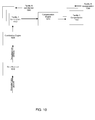
- Figure 10 is a block diagram illustrating the flow of data at an accounting server according to one embodiment of the present invention.
- the encrypted data packets are received by a data receiver 1010 at accounting server 740.
- the packets are decrypted by the receiver and forwarded to contribution engine 1020 for determining the contribution amounts from the decrypted data.
- Contribution engine 1020 is operable to recognize contributions from the various monitoring stations at the connected power generating facilities 720 and keep track of the contribution from each of the facilities. For example, in Figure 10 , contribution engine 1020 keeps track of the contribution 1050 from Facility 1 separately from contribution 1060 from Facility N.
- the respective contribution information is then passed to a compensation engine 1070.
- the compensation engine 1070 is responsible for converting the contribution amounts from each of the respective facilities to compensation amounts. For example, compensation engine 1070 will determine a separate compensation amount 1090 for Facility 1 based on the contribution amount 1050 for Facility 1. Further, it will determine a separate compensation amount 1080 for Facility N based on the contribution amount 1060 for Facility N.
- FIG 11 is a block diagram illustrating the flow of data at a FPGM in accordance with one embodiment of the present invention.
- current sense module 146 determines the amount of outgoing electricity at a FPGM 620.
- the data collected by current sense module 146 is used by the power contribution computation engine 1102 to determine the amount of power contributed back into the grid from FGP 650.
- the data packetizer 1104 transforms the power contribution data from power contribution computation engine 1102 into ECC packets 710.
- Data packetizer 1104 also receives timing information, wherein the timing information is used to time-stamp the ECC data packets.
- the ECC data packets 710 are encrypted using data encryption engine 1106.
- Data encryption engine 1106 may receive encryption, certificates and signing keys from keys storage module 148.
- the encrypted or signed data is subsequently transmitted to an accounting server using data transmitter module 1108.
- the embodiments disclosed herein may also be implemented using software modules that perform certain tasks. These software modules may include script, batch, or other executable files that may be stored on a computer-readable storage medium or in a computing system. These software modules may configure a computing system to perform one or more of the example embodiments disclosed herein.
- One or more of the software modules disclosed herein may be implemented in a cloud computing environment. Cloud computing environments may provide various services and applications via the Internet.
- cloud-based services e.g., software as a service, platform as a service, infrastructure as a service, etc.
- Various functions described herein may be provided through a remote desktop environment or any other cloud-based computing environment.
Abstract
Description
- This application claims priority from
U.S. Provisional Patent Application Serial No. 61/624,190 - Embodiments according to the present invention generally relate to systems involving power generation and distribution and more specifically to methods for measuring and accounting for generated and distributed power.
- Historically, electrical power has been delivered from a power generation facility, for example, Northern California Power Agency ("NCPA"), to an end-consumer at a home or business facility through an electricity distributor, for example, Pacific, Gas and Electricity Company ("PG&E"). The power can usually be provisioned from any kind of power generation facility, for example, a hydroelectric, coal or steam plant. The electricity distributor, on the other hand, owns the grid of wires and sub-stations that distribute power to the consumers and is typically unrelated to the power provisioning facility. The end-consumer, traditionally, has not had any means to produce power locally at his or her home or business facility. The local home or business facility, therefore, has only needed to be equipped with electricity meters capable of measuring electricity drawn from the grid for supplying the power demands of the facility.
-
Figure 1 illustrates a historical power generation and distribution system. Power is generated by apower generator 150 and then delivered toelectricity consumers 160 through a power distributor orgrid provider 155. - This historical model has presently evolved into one where the end consumers have the capability of generating their own power, for example, through the advent of home solar electric panels, blume gas generators, fuel cells, and wind turbines. Therefore, the traditional electricity meters have needed to be adapted to also account for how much power is being supplied back into the grid. This is accomplished, for example, by allowing the meters to "run backwards," whereupon the grid provider would provide a refund for the amount of kilowatt-hours ("kwh") supplied back into the grid. However, under the present model, the electricity provider is still in charge of accounting for contributions and determining the compensation scale for the contribution.
-
Figure 2 illustrates a conventional power generation and distribution system as it exists presently. Power is generated by apower generator 250 and distributed to the consumers through anelectricity distributor 255 similar to historical systems. However, in the conventional power generation and distribution systems of today,certain consumers 275 have means of generating electricity at their own facility through the use of, for example, solar panels. - The problem with the present model of power distribution and accounting is that consumer power generation capabilities are in effect competing with corporate generation, and the corporations, in particular, the grid providers, may choose to reward contributions back into the grid at a much reduced rate, substantially lower than the price the electricity supplier would charge consumers drawing from the grid. This is problematic especially because while the purchase and installation cost of the solar electric panels is less per kwh over the life of the solar panels than the cost of the electricity drawn from the grid, it is typically more expensive than the amount refunded by the electricity distributor corporations for supplying power back into the grid.
- These constraints have, in effect, placed an economic limit on the practical size of a home or business solar panel installation for a typical consumer. In short, if the installation produces more electricity than the typical electrical demand of the home on which it is fitted, it simply cannot recoup the cost of the installation through the money refunded through oversupply going back into the grid. Unfortunately, this leads to an artificial constraint on the typical home generation installation, wherein the policy of the electricity distributor for the amount of money refunded rather than the installation area or other physical capability of the installation site is the key determinative factor governing the size of the clean solar home generation installation.
- For example, a typical electricity supplier or distributor may charge $0.41 per kwh for a tier one electrical consumer at the peak demand time, while refunding surplus electricity contributed back into the grid at only $0.11 per kwh. Meanwhile, a typical solar installation may cost $0.22 per kwh over the life of the panel. Under this model, it makes little economic sense for a typical consumer to utilize a solar installation with excess capacity over what the consumer's home or business demands, because any oversupply contributed back into the grid will not be compensated at the same rate as the power consumed. Similarly, a factory employing wind turbines would face a similar dilemma if the size of the turbine results in excess capacity over what the local facility demands.
- Since the electricity generated by solar panel, wind turbine, or a coal fired generating facility is the same once it is on the grid, there is no reason why one form of power generation should earn less per kwh than any other method, whether it is solar, wind, geothermal or other. However, the problem with sources of electricity being fungible is that it is challenging to distinguish electricity contributed by one provider from another. Therefore, it is problematic to account for the contributions from the various different types of electricity providers.
- Accordingly, a need exists for a system wherein the electrical contribution of any generation facility can be accounted for fairly and securely. Also what is needed is a robust method of accounting for electricity contribution at the source of the power supply into the grid. Using the beneficial aspects of the systems described, without their respective limitations, embodiments of the present invention provide a novel solution to address these problems.
- Disclosed herein is a method whereby each facility's power contribution can be recorded, tallied and time-stamped by one or more independent auditing bodies allowing the formation of virtual electricity suppliers.
- In one embodiment, a method of accounting for electrical power contributions is presented. The method comprises receiving encrypted data from a plurality of facilities, wherein the plurality of facilities is operable to generate electricity, and wherein the encrypted data comprises information concerning electricity contributions to a power grid by the plurality of facilities. The method further comprises decrypting the encrypted data to access information concerning electricity contributions. Finally, the method comprises tracking electricity contributions from each of the plurality of facilities using decrypted data. The method can also comprise compensating each of the plurality of facilities based on the respective electricity contribution of each facility.
- Embodiments include the above and further comprise determining compensation for each of the first plurality of facilities based on the respective electricity contribution of each facility.
- Embodiments include the above and wherein the encrypted data is encrypted using a public key cryptographic system.
- Embodiments include the above and wherein the public key cryptographic system is selected from a group comprising: public key distribution system, digital signature system and public key cryptosystem.
- Embodiments include the above and wherein the public key cryptographic system uses a RSA algorithm.
- Embodiments include the above and wherein the first plurality of facilities is further operable to consume electricity, and further wherein the encrypted data comprises information concerning electricity consumption from a power grid by the first plurality of facilities.
- Embodiments include the above and further comprising accounting for electricity consumption by each of the first plurality of facilities using the decrypted data.
- Embodiments include the above and further comprising: (a) receiving data from a second plurality of facilities, wherein the second plurality of facilities is operable to consume electricity, and wherein the data comprises information concerning electricity consumption from the power grid by the second plurality of facilities; and (b) accounting for respective electricity consumption for each of the second plurality of facilities using received data.
- Embodiments include the above and further comprising determining a compensation amount for a grid provider for a portion of electricity consumed by the first plurality of facilities and the second plurality of facilities, wherein the portion of electricity is contributed by the grid provider, and wherein determinations for a compensation amount to the grid provider are based on information concerning electricity consumption received from the first plurality of facilities and the second plurality of facilities.
- Embodiments include the above and wherein the first plurality of facilities and the second plurality of facilities form a virtual power generation network.
- Embodiments include the above and further comprising selling surplus electricity produced by the first plurality of facilities to consumers within the virtual power generation network.
- Embodiments include the above and wherein the encrypted data comprises data packets, wherein the data packets comprise: (a) power contribution measured as an integral of power over time; (b) a timestamp comprising the time of day at which the power contribution is recorded; and (c) a period of time over which the power contribution is measured.
- Embodiments include the above and wherein the encrypted data is received from the first plurality of facilities by querying a monitoring station located at each of the first plurality of facilities.
- In one embodiment, an apparatus for measuring power is presented. The apparatus comprises a meter coupled to a power generation plant at a local facility, wherein the meter comprises: (a) a current sense module operatively coupled to a processor, wherein the processor in conjunction with the current sense module is operable to compute power contributed by the power generation plant; (b) a memory operable to store computed power contribution, and a first set of encryption keys used to communicate securely with a grid provider; and (c) a network interface operable to communicate with the grid provider, wherein a communication between the meter and the grid provider is secured using the first set of encryption keys, and wherein the communication comprises relaying the computed power contributions to the grid provider.
- In another embodiment, a system of accounting for electrical power contributions is presented. The system comprises an accounting server communicatively coupled to a plurality of facilities, wherein the plurality of facilities is operable to generate electricity. The accounting server comprises a memory operable to store accounting information concerning electrical contributions from the plurality of facilities and a tracking application. The server also comprises a network interface for communicating with the plurality of facilities and a processor coupled to the memory and the network interface. The processor is configured to operate in accordance with the tracking application to (a) receive encrypted data from the plurality of facilities, wherein the encrypted data comprises information concerning electricity contributions to a power grid by the plurality of facilities; (b) decrypt the encrypted data to access the information concerning electricity contributions; and (c) track electricity contributions from each of the first plurality of facilities using decrypted data.
- In a different embodiment, a method of accounting for aggregate electrical power contributions from a distributed network of contributing facilities is disclosed. The method comprises receiving information originating from a first plurality of monitoring stations associated with a first plurality of facilities, wherein the first plurality of facilities is operable to generate as well as consume electricity, and wherein the information from the monitoring stations comprises information concerning electricity metered flowing onto a power grid from the first plurality of facilities, or electricity consumption metered flowing into the first plurality of facilities. Further, the first plurality of facilities agree to co-operatively account for their collective contribution and consumption as a collective. Additionally, the information from the first plurality of facilities is transmitted to a collective-authorized entity for combination into an aggregate total of power contribution and an aggregate total of power consumption by the first plurality of facilities. Finally, the aggregate total of power contribution is presented as a whole to enable representation of the collective's energy generation capability as a single entity.
- Embodiments of the present invention are illustrated by way of example, and not by way of limitation, in the figures of the accompanying drawings and in which like reference numerals refer to similar elements.
-
Figure 1 illustrates a historical power generation and distribution system. -
Figure 2 illustrates a conventional power generation and distribution system as it exists presently. -
Figure 3 illustrates an electricity generation and distribution system in accordance with one embodiment of the present invention. -
Figure 4 is an exemplary computing system for a facility power generation meter ("FPGM") in accordance with embodiments of the present invention. -
Figure 5 is a block diagram of an example of a network architecture in which client FPGMs and servers may be coupled to a network, according to embodiments of the present invention. -
Figure 6 is a block diagram illustrating a more detailed view of a virtual electricity distribution system at the source of the power supply in accordance with embodiments of the present invention. -
Figure 7 is a high level block diagram illustrating the components of a virtual electricity generation and distribution system in accordance with one embodiment of the present invention. -
Figure 8 depicts aflowchart 800 of an exemplary process of securely accounting for electricity contribution according to an embodiment of the present invention. -
Figure 9 depicts aflowchart 900 of an exemplary process of sensing electricity contributions and securely transmitting packets reporting electricity contribution to an accounting server according to an embodiment of the present invention. -
Figure 10 is a block diagram illustrating the flow of data at an accounting server according to one embodiment of the present invention. -
Figure 11 is a block diagram illustrating the flow of data at a FPGM in accordance with one embodiment of the present invention. - In the figures, elements having the same designation have the same or similar function.
- Reference will now be made in detail to the various embodiments of the present disclosure, examples of which are illustrated in the accompanying drawings. While described in conjunction with these embodiments, it will be understood that they are not intended to limit the disclosure to these embodiments. On the contrary, the disclosure is intended to cover alternatives, modifications and equivalents, which may be included within the spirit and scope of the disclosure as defined by the appended claims. Furthermore, in the following detailed description of the present disclosure, numerous specific details are set forth in order to provide a thorough understanding of the present disclosure. However, it will be understood that the present disclosure may be practiced without these specific details. In other instances, well-known methods, procedures, components, and circuits have not been described in detail so as not to unnecessarily obscure aspects of the present disclosure.
- Some portions of the detailed descriptions that follow are presented in terms of procedures, logic blocks, processing, and other symbolic representations of operations on data bits within a computer memory. These descriptions and representations are the means used by those skilled in the data processing arts to most effectively convey the substance of their work to others skilled in the art. In the present application, a procedure, logic block, process, or the like, is conceived to be a self-consistent sequence of steps or instructions leading to a desired result. The steps are those utilizing physical manipulations of physical quantities. Usually, although not necessarily, these quantities take the form of electrical or magnetic signals capable of being stored, transferred, combined, compared, and otherwise manipulated in a computer system. It has proven convenient at times, principally for reasons of common usage, to refer to these signals as transactions, bits, values, elements, symbols, characters, samples, pixels, or the like.
- It should be borne in mind, however, that all of these and similar terms are to be associated with the appropriate physical quantities and are merely convenient labels applied to these quantities. Unless specifically stated otherwise as apparent from the following discussions, it is appreciated that throughout the present disclosure, discussions utilizing terms such as "determining," "accounting," "receiving," "tracking," "encrypting," "decrypting," "allocating," "associating," "accessing," "determining," "identifying," or the like, refer to actions and processes (e.g.,
flowchart 800 ofFigure 8 ) of a computer system or similar electronic computing device or processor (e.g.,system 110 ofFigure 4 ). The computer system or similar electronic computing device manipulates and transforms data represented as physical (electronic) quantities within the computer system memories, registers or other such information storage, transmission or display devices. - Embodiments described herein may be discussed in the general context of computer-executable instructions residing on some form of computer-readable storage medium, such as program modules, executed by one or more computers or other devices. By way of example, and not limitation, computer-readable storage media may comprise non-transitory computer-readable storage media and communication media; non-transitory computer-readable media include all computer-readable media except for a transitory, propagating signal. Generally, program modules include routines, programs, objects, components, data structures, etc., that perform particular tasks or implement particular abstract data types. The functionality of the program modules may be combined or distributed as desired in various embodiments.
- Computer storage media includes volatile and nonvolatile, removable and non-removable media implemented in any method or technology for storage of information such as computer-readable instructions, data structures, program modules or other data. Computer storage media includes, but is not limited to, random access memory (RAM), read only memory (ROM), electrically erasable programmable ROM (EEPROM), flash memory or other memory technology, compact disk ROM (CD-ROM), digital versatile disks (DVDs) or other optical storage, magnetic cassettes, magnetic tape, magnetic disk storage or other magnetic storage devices, or any other medium that can be used to store the desired information and that can accessed to retrieve that information.
- Communication media can embody computer-executable instructions, data structures, and program modules, and includes any information delivery media. By way of example, and not limitation, communication media includes wired media such as a wired network or direct-wired connection, and wireless media such as acoustic, radio frequency (RF), infrared, and other wireless media. Combinations of any of the above can also be included within the scope of computer-readable media.
- METHOD AND APPARATUS TO FORM A VIRTUAL POWER GENERATION COLLECTIVE FROM A DISTRIBUTED NETWORK OF LOCAL GENERATION
- Embodiments of the present invention relate generally to collecting measurements of power contribution and more specifically to a method and system of determining power generation capability in a distributed network of local generation facilities. Accordingly, embodiments of the present invention provide a system wherein the electrical contribution of any generation facility can be accounted for fairly and securely. Also embodiments of the present invention provide a robust method of accounting for electricity contribution at the source of the power supply into the grid. With the fair and secure accounting of electricity contributions of the present invention, an open market can be realized wherein any producer of electricity can be fairly rewarded according to the size and efficiency of their contribution.
-
Figure 3 illustrates an electricity generation and distribution system in accordance with one embodiment of the present invention. Power is generated by apower generator 350 and distributed to the consumers through anelectricity distributor 355 similar to conventional systems discussed above. However, forcertain consumers 370 that have a means for generating electricity at their own facility, one embodiment of the present invention provides a virtual electricity anddistribution hub 390 that aggregates and keeps track of the various power contributions from thehome electricity producers 370. - Another embodiment of the present invention allows power generated by each
local facility 370 to be recorded and robustly acknowledged so that each producer at thelocal facility 370 can verify that their contribution is recognized and further verify that they are being fairly compensated for their contribution. - One embodiment of the present invention allows for verification that the power generated by one or more
local facilities 370 represents an actual contribution to the grid. This is important because it allows thelocal facilities 370 to recognize, verify and accept that the contribution made by other contributing facilities into the grid is not being falsified. - Another embodiment of the present invention keeps track of and accounts for the time at which the power contribution is made, thereby, providing support for flexible compensation for power generation. The compensation can be adjusted to more fairly compensate electricity provided from local generation facilities and from providers that generate electricity on demand or at times when wind, sun and other natural sources of electricity are less abundant. For example, entities that generate power at night, when solar panels at the local facilities are not running as efficiently, can be compensated at a higher rate to compensate their higher cost of power generation.
- In one embodiment, once the contribution of one or more facilities to the grid can be robustly and accurately recognized, the facilities can form a conglomerate or a virtual power generation organization for the purpose of keeping track of and accounting for the contributions of conglomerate members and creating a single virtual organization. Such a virtual organization would have the advantage of presenting a single face to promote and charge consumers, and to facilitate the distribution of funds to producers according to contribution. For example, virtual electricity generation and
distribution hub 390 inFigure 3 can, in one embodiment, be a virtual power generation organization comprising a plurality of local power generation facilities that keeps track of the contributions from its various members and apportions funds accordingly. In one embodiment, the virtual power generation organization could be set up to allow any participating facility within the organization to purchase electricity directly from another participating facility. For example, a facility could end up purchasing electricity directly from a neighboring facility under this arrangement. - Individual home electricity contributors can benefit from joining other home contributors in the formation of a virtual power generation collective. One advantage in forming a virtual power collective is that it would simplify the accounting and billing process. The virtual power generation organization may take a percentage of the total amount collected to cover their costs and overhead. Further, the compensation paid out by the virtual power collective may be applied more fairly by the contributors within the conglomerate towards the future development of new facilities or larger facilities for electricity production.
- Further, compensating the individual contributors fairly would likely encourage continued investment in larger home generation facilities. Another advantage of the present invention is that by making installation of larger home generation facilities more economically attractive, demand for more generation capability and, in particular, more efficient generation capability is driven up. Accordingly, facilitating virtual power generation capability can create a new power generation economy by providing an organically created economic stimulus for purchasing of local electricity generation capabilities, for example, home solar panels. It can also drive an increased investment in technologies to improve the efficiency of small scale power generation capabilities, e.g. home fuel cells.
- Additionally, the ability to recognize and distinguish the contributions from the various facilities, or conglomerate of facilities, into the grid can provide consumers the ability, in one embodiment, to choose to compensate whichever entity they prefer to pay for their supply of electricity. For example, a consumer may choose to pay a local virtual power generation organization formed from the combined contributions of multiple local home power generation facilities within the consumer's community.
- One objective of the present invention is to connect suppliers and consumers via a virtual electric grid formed from networked micro-generation capable facilities. Connecting the suppliers and consumers allows small scale producers of solar, wind and geothermal energy to collaborate together to collect compensation or funding for facility maintenance and improvement.
As an increasing number of local electricity generating facilities such as solar panels are being installed on a smaller scale, for example, in residential homes and corporate facilities, the ability of these facilities to contribute power back into the grid as well as support local demand for further installations continues to grow. - As the number of distributed local generation facilities grows, the opportunity arises for these facilities to collect and pool their contributions by forming a Virtual Power Generation Network ("VPGN"). A VPGN can be a collection of power generation facilities, which operate collectively to form a distributed power generation capability. When a VPGN is available on a grid as a power provider, other electricity consumers have an option to then purchase electricity from the VPGN. Since the VPGN is established via a robust data collection through accounting for each facility's contribution to the VPGN, it is then possible to account for the contribution of each local generation facility and to distribute funding according to amount of contribution and the time stamp on when the contribution was made. In essence, the power distribution and accounting system of the present invention allows all the contributions from the various facilities to be accounted for in a "cloud", whereby individual consumers can buy electricity for their personal use directly from the cloud.
- In one embodiment, a facility power generation meter ("FPGM") is located at each facility, which counts the power either drawn from or supplied to the grid from the facility generation plant ("FGP"). The FGP is the power generation capability local to a particular facility, e.g., solar panels at the facility. Each FPGM is connected to a grid provider ("GP"), which is the owner of the neighborhood electrical connection to the facility.
-
Figure 4 illustrates anexemplary computing system 110 for a facility power generation meter ("FPGM") in accordance with embodiments of the present invention.Computing system 110 broadly represents any single or multi-processor computing device or system capable of executing computer-readable instructions. In its most basic configuration,computing system 110 may include at least oneprocessor 114 and asystem memory 116. -
Processor 114 generally represents any type or form of processing unit capable of processing data or interpreting and executing instructions. In certain embodiments,processor 114 may receive instructions from a software application or module. These instructions may causeprocessor 114 to perform the functions of one or more of the example embodiments described and/or illustrated herein. -
System memory 116 generally represents any type or form of volatile or non-volatile storage device or medium capable of storing data and/or other computer-readable instructions. Examples ofsystem memory 116 include, without limitation, RAM, ROM, flash memory, or any other suitable memory device. Although not required, in certainembodiments computing system 110 may include both a volatile memory unit (such as, for example, system memory 116) and a non-volatile storage device (such as, for example, primary storage device 132). -
Computing system 110 may also include one or more components or elements in addition toprocessor 114 andsystem memory 116. For example, in the embodiment ofFigure 4 ,computing system 110 includes amemory controller 118, an input/output (I/O)controller 120, and acommunication interface 122, each of which may be interconnected via acommunication infrastructure 112.Communication infrastructure 112 generally represents any type or form of infrastructure capable of facilitating communication between one or more components of a computing device. Examples ofcommunication infrastructure 112 include, without limitation, a communication bus (such as an Industry Standard Architecture (ISA), Peripheral Component Interconnect (PCI), PCI Express (PCIe), or similar bus) and a network. -
Memory controller 118 generally represents any type or form of device capable of handling memory or data or controlling communication between one or more components ofcomputing system 110. For example,memory controller 118 may control communication betweenprocessor 114,system memory 116, and I/O controller 120 viacommunication infrastructure 112. - I/
O controller 120 generally represents any type or form of module capable of coordinating and/or controlling the input and output functions of a computing device. For example, I/O controller 120 may control or facilitate transfer of data between one or more elements ofcomputing system 110, such asprocessor 114,system memory 116,communication interface 122,display adapter 126,input interface 130, andstorage interface 134. -
Communication interface 122 broadly represents any type or form of communication device or adapter capable of facilitating communication betweenexample computing system 110 and one or more additional devices. For example,communication interface 122 may facilitate communication betweencomputing system 110 and a private or public network including additional computing systems. Or, for example,communication interface 122 may facilitate communication between the FPGM and the grid provider. Examples ofcommunication interface 122 include, without limitation, a wired network interface (such as a network interface card), a wireless network interface (such as a wireless network interface card), a modem, and any other suitable interface. In one embodiment,communication interface 122 provides a direct connection to a remote server via a direct link to a network, such as the Internet.Communication interface 122 may also indirectly provide such a connection through any other suitable connection. -
Communication interface 122 may also represent a host adapter configured to facilitate communication betweencomputing system 110 and one or more additional network or storage devices via an external bus or communications channel. Examples of host adapters include, without limitation, Small Computer System Interface (SCSI) host adapters, Universal Serial Bus (USB) host adapters, IEEE (Institute of Electrical and Electronics Engineers) 1394 host adapters, Serial Advanced Technology Attachment (SATA) and External SATA (eSATA) host adapters, Advanced Technology Attachment (ATA) and Parallel ATA (PATA) host adapters, Fibre Channel interface adapters, Ethernet adapters, or the like.Communication interface 122 may also allowcomputing system 110 to engage in distributed or remote computing. For example,communication interface 122 may receive instructions from a remote device, for example, at the grid provider's end, or send instructions to a remote device for execution. - In one embodiment, the
communication interface 122 on the FPGM can connect to the network through one of various protocols, e.g., wirelessly through a Wi-Fi connection, or through a wired Ethernet connection or even by communicating using Ethernet over power cables. - As illustrated in
Figure 4 ,computing system 110 may also include at least onedisplay device 124 coupled tocommunication infrastructure 112 via adisplay adapter 126.Display device 124 generally represents any type or form of device capable of visually displaying information forwarded bydisplay adapter 126. Similarly,display adapter 126 generally represents any type or form of device configured to forward graphics, text, and other data for display ondisplay device 124. - As illustrated in
Figure 4 ,computing system 110 may also include at least oneinput device 128 coupled tocommunication infrastructure 112 via aninput interface 130.Input device 128 generally represents any type or form of input device capable of providing input, either computer- or human-generated, tocomputing system 110. Examples ofinput device 128 include, without limitation, a keyboard, a pointing device, a speech recognition device, or any other input device. - As illustrated in
Figure 4 ,computing system 110 may also include aprimary storage device 132 and abackup storage device 133 coupled tocommunication infrastructure 112 via astorage interface 134.Storage devices storage devices Storage interface 134 generally represents any type or form of interface or device for transferring data betweenstorage devices computing system 110. - In one embodiment, the FPGM can also include
storage 148 to store encryption keys used to communicate with the grid provider or VPGNs.Storage 148 can be separate from or part of theprimary storage device 132. Also, in one embodiment, all the storage employed insystem 110 would either be secure or use code signing techniques to ensure secure storage and execution of programs and software on the FPGM . - In one example,
databases 140 may be stored inprimary storage device 132.Databases 140 may represent portions of a single database or computing device or it may represent multiple databases or computing devices. For example,databases 140 may represent (be stored on) a portion ofcomputing system 110 and/or portions ofexample network architecture 200 inFigure 2 (below). Alternatively,databases 140 may represent (be stored on) one or more physically separate devices capable of being accessed by a computing device, such ascomputing system 110 and/or portions ofnetwork architecture 200. - Continuing with reference to
Figure 4 ,storage devices Storage devices computing system 110. For example,storage devices Storage devices computing system 110 or may be separate devices accessed through other interface systems. - In one embodiment, the
processor 114 is capable of processing data from power detection (or current sense)circuit 146 that is received subsequent to being processed through an analog todigital converter 144. Theprocessor 114, in one embodiment, can also be programmed to compute a history of power production and consumption. - Many other devices or subsystems may be connected to
computing system 110. Conversely, all of the components and devices illustrated inFigure 4 need not be present to practice the embodiments described herein. The devices and subsystems referenced above may also be interconnected in different ways from that shown inFigure 4 .Computing system 110 may also employ any number of software, firmware, and/or hardware configurations. For example, the example embodiments disclosed herein may be encoded as a computer program (also referred to as computer software, software applications, computer-readable instructions, or computer control logic) on a computer-readable medium. - The computer-readable medium containing the computer program may be loaded into
computing system 110. All or a portion of the computer program stored on the computer-readable medium may then be stored insystem memory 116 and/or various portions ofstorage devices processor 114, a computer program loaded intocomputing system 110 may causeprocessor 114 to perform and/or be a means for performing the functions of the example embodiments described and/or illustrated herein. Additionally or alternatively, the example embodiments described and/or illustrated herein may be implemented in firmware and/or hardware. -
Figure 5 is a block diagram of an example of a network architecture in whichclient FPGMs servers network 250, according to embodiments of the present invention.Servers client FPGMs Servers server 240 may belong to the VPGN whileserver 245 may belong to the grid provider's network.Client systems computing system 110 ofFigure 4 . - Similarly,
servers Network 250 generally represents any telecommunication or computer network including, for example, an intranet, a wide area network (WAN), a local area network (LAN), a personal area network (PAN), or the Internet. - With reference to
computing system 110 ofFigure 4 , a communication interface, such ascommunication interface 122, may be used to provide connectivity between eachclient system network 250.Client systems server client systems server 240,server 245, storage devices 260(1)-(L), storage devices 270(1)-(N), storage devices 290(1)-(M), orintelligent storage array 295. AlthoughFigure 5 depicts the use of a network (such as the Internet) for exchanging data, the embodiments described herein are not limited to the Internet or any particular network-based environment. - In one embodiment, all or a portion of one or more of the example embodiments disclosed herein are encoded as a computer program and loaded onto and executed by
server 240,server 245, storage devices 260(1)-(L), storage devices 270(1)-(N), storage devices 290(1)-(M),intelligent storage array 295, or any combination thereof. All or a portion of one or more of the example embodiments disclosed herein may also be encoded as a computer program, stored inserver 240, run byserver 245, and distributed toclient systems network 250. -
Figure 6 is a block diagram illustrating a more detailed view of a virtual electricity distribution system at the source of the power supply in accordance with embodiments of the present invention. Alocal facility 630 that is part of the VPGN may have a local facility generation plant ("FGP") as discussed above. For example, the FGP may comprisesolar panels 650 as shown inFigure 6 . Where solar panels are being used to generate power, asolar inverter 640 may be part of the installation at the local facility.Inverter 640 converts the variable direct current (DC) output of a photovoltaic solar panel into a utility frequency alternating current that can be fed into a commercial electrical grid or used by the local off-grid electrical network.
TheFPGM 620 that is at the source of the power supply may be used to keep track of the electricity contribution and consumption of therespective facility 630 to which it is connected. - In one embodiment, each
FPGM 620 at each facility needs to have a secure means of communicating over the network, e.g., to agrid provider 660 or theVPGN 610. This can be done by ensuring that all data transmitted to and from a FPGM is encrypted. Encrypting the data ensures that there is integrity to the system and that each facility's contribution can be accounted for accurately. In one embodiment, public key cryptography using asymmetric key algorithms such as RSA can be used to encrypt the data. In another embodiment, any of the three primary kinds of public key cryptography systems can be used, namely, public key distribution systems, digital signatures system, and public key cryptosystems. The three kinds of public key systems can perform both public key distribution and digital signature services. For example, well known algorithms such as Diffie-Hellman key exchange, which is a type of public key distribution system, and Digital Signature Algorithm, which is a type of digital signature system, can be used. However, the invention is not limited to only using public key cryptographic algorithms. Any number of various methods and algorithms may be used to encrypt FPGM data. - Where public key cryptographic techniques are used, each FPGM at a subscriber's site may comprise a private key and a public key pair. This private and public key pair can be provided by, for example, the grid provider. The FPGM may report its power consumption or contribution to the
grid provider server 660 using Energy Contribution Count data packets ("ECC") overnetwork interface 122 as discussed above.
The ECC data packets can comprise the power contribution measured as an integral of power over time (watt-hours). It can also include a timestamp, including the time of day in which the contribution was recorded. Also, it can include a number identifying its order in the sequence of ECC packets transmitted. Further, it can include the unit of time over which the energy consumption or production was measured. It may include the amount of power, the direction of power flow, and the duration of flow. In addition, it can also include the integral of contribution over the time interval. It may include one or more historical integrals summing the contribution over longer intervals. It may include facility location or location within the facility, facility identifier, as well as the type of generation. It may include the method of power generation at the facility, such as whether wind, solar, thermal or other generation method. Finally it may include recipient supplied information such as recipient and facility identifiers, recipient supplied cryptographic nonce. By including the integrals of contributions over certain time intervals, the ECCs protect against data being lost due to network outages or other potential transmission errors, because the integrals may used to reconstruct the contribution data. - In one embodiment where public key cryptography is used, the
FPGM 620 can sign the ECC with a private key provided by the grid provider. It also can include a certificate signed by the grid provider (or other recognized signing authority), which includes a matching public key, thereby, allowing the ECC to be decrypted at the receiving end. - In one embodiment, the
FPGM 620 may be programmed to include signatures of the prior ECCs in subsequent ECCs as a way to protect against tampering. Further, forensic data collection techniques can be used to examine the history of ECC packets to verify lost data packets. Also, the FPGMs can be programmed to continue including past ECC signatures in subsequent packets until receipt of transmission from the grid provider acknowledging receipt of the ECC. This mechanism allows the history of contribution and consumption for a particular FPGM to be recreated easily. - In one embodiment, the FPGM includes a mechanism to perform a handshake with the auditing server, e.g., the grid provider's
server Figure 5 . For example, the auditing server can transmit certain verification information to be introduced into the signature in order to verify the data received from the FPGM. The verification information can comprise timestamps, recipient supplied nonce, sequential numbers, or other identification information that can be integrated into the signature by the FPGM to provide robustness for the information being transmitted. - In another embodiment, the FPGM may utilize one of many different techniques to transmit the energy count to the grid provider's network using the ECCs. For example, the FPGM can transmit data over the grid's wired network to the sub-station. Alternatively, the FPGM may transmit the ECCs over local facility wireless networks, e.g., through WiFi access points at the local facility. Or the FPGM may transmit the energy counts to the grid provider via wireless mesh networks formed from neighboring facilities with similar FPGMs.
- The sub-station collects the ECC packets transmitted by the various FPGMs, verifies the signatures and accumulates the contributions of each FGP. It can also run audit checks. The auditing process can identify tampering or falsified contributions. It can also identify situations where an FGP's ECC data is missing, e.g., due to a local network failure.
- In one embodiment, where data collection is not possible over the network, for example, because of a network outage or because of a facility's remote location, or where the data may need to be collected manually, for example, to detect tampering or falsification, a technician may visit a FGP at the
local facility 630 and collect the data manually from aFPGM 620 using a handheld collection device. Holding the device in close proximity to the FPGM, the FPGM may transmit data to the handheld collection device using Infra-Red, Near Field wireless technologies, Bluetooth, Electromagnetic Induction, or other non-contact, and direct electrical interface contact data transmission mechanisms. - In one embodiment, as the handheld collection device downloads ECC data from the
FPGM 620, the meter and device may confirm each time interval recorded. The FPGM may subsequently insert this download confirmation into subsequent ECC data signatures. The confirmation may comprise a serial number of the handheld collective device, the last timestamp collected and the time intervals collected. - As discussed above, in one embodiment, the ECC is signed with a timestamp, recording when a unit of power has been supplied into the grid. By including the unit of time over which an energy contribution was made, the ECC allows both power and time to be factored into the running integral, thereby, allowing a long term average to be computed. As acknowledgements of the ECCs are received back from the VPGN, these may be accumulated in the long term average, to allow the facility to observe the net amount of electricity supplied versus net amount accounted for by the VPGN, and thus verify contributions are being recognized.
- Similar to how the
FPGM 620 reports information to the grid provider, the FPGM, in one embodiment, may also communicate with theVPGN server 610 via thenetwork interface 122 or through a manual collection process. The FPGM sends the ECC and the signature to theVPGN server 610. The VPGN server records and performs the accounting for all FGP contributions by examining the ECC and verifying it using the respective signature. If verified, the VPGN can respond to the FPGM with another signature of the ECC using a separate private/public key pair from the one used to securely communicate with the grid provider, in instances where public key cryptographic techniques are being utilized. Upon recognizing that the VPGN has processed an ECC, the FPGM may convey the pertinent information to the local electricity producing consumers. The consumers can use this information to verify that their contribution have been received and accounted. As the VPGN verifies each ECC received, it accumulates and records the contribution of each FGP so that in the subsequent payment cycle, each respective FGP may be appropriately compensated according to its contribution. - In one embodiment, the VPGN may also receive packets from the FPGMs corresponding to the electricity consumed by the local facilities subscribing to the VPGN power distribution and supply network. However, existing meters operated using conventional methods can also be used to report back the power consumption by the local facilities. The power production and consumption data received from each local facility can be used to compute the amount billed to each local facility consumer in the event that more power is drawn than contributed by the respective local facility consumer, or compute the amount to be compensated to each local facility consumer in the event that more power is contributed by the facility than drawn from the grid.
-
Figure 7 is a high level block diagram illustrating the components for a virtual electricity generation and distribution system (i.e. a VPGN) in accordance with one embodiment of the present invention. Each VPGN can be a conglomerate of distributed local electricity generation facilities. A VPGN, in one embodiment, may not only be a collection ofpower generating facilities 720, but also be available on a grid as a power provider, thereby, allowingelectricity consumers 730 to also be part of the VPGN. When a VPGN is available on a grid as a power provider, other electricity consumers have an option to then purchase electricity from the VPGN. The power distribution and accounting system of the present invention allows all the contributions from the various distributedproduction facilities 720 to be accounted for in acloud 750. Also,individual electricity consumers 730 can buy electricity for their personal use directly from thecloud 750. At the back-end, anaccounting server 740, similar toservers Figure 2 , can keep track of the contribution and consumption levels of the various local facilities. - In one embodiment,
producers 720 may be able to query the FPGM at their own local facility to verify their contribution or consumption history, and also query theaccounting server 740 at the VPGN to determine whether their contributions are being fairly accounted for. For example, aproducer 720 may be equipped with its own handheld collection device to collect data from the FPGM or theproducer 720 may have some other manual means of doing a data dump from the FPGM. Alternatively, the FPGM could be connected throughnetwork interface 122 to the producer's personal computer allowing the consumer to interface with the FPGM through a Wi-Fi or web interface. One advantage of storing all the consumers' and producers' data in acloud 750 is the ability for all the various entities that are part of a VPGN to be able to verify their respective contribution and consumption conveniently. - In one embodiment, the VPGN and the grid provider could also collaborate in order to, among other things, verify that all the contribution and consumption amounts have been accounted for fairly and accurately. If a VPGN and the grid provider are to share a grid, some type of collaboration between the two entities would be envisioned under the scheme proposed by the present invention. For example, a grid provider would need to audit the various compensation amounts to the local facilities so as to ensure that they are paying out accurate and fair amounts for the power contributed to the grid by the facilities and also being compensated for any net power being consumed by the facilities.
- Further, collaboration between a VPGN and the grid provider, e.g., PG&E would facilitate compensation sharing between the various power provisioning entities. For example, in one embodiment, there could be an accounting for the percentage of power contributed by the grid provider to the facilities that constitute a particular VPGN network versus the percentage of power contributed by the facilities within the VPGN. In this way, the grid provider could be fairly compensated for the percentage of power contributed by it, while each of the facilities within the VPGN could be compensated for the amount of power contributed by the respective facility. In one embodiment, instead of splitting compensation on a percentage basis, each of the facilities, including the grid provider, could be compensated per kwh contributed to the grid.
- In one embodiment, the grid provider may continue to charge the consumers directly for the net power consumed by them as determined from the auditing info received from the various FPGMs at the local facilities.
- In another embodiment, the consumers could buy their power directly from the VPGN rather than the grid provider and VPGN could sub-contract with the grid provider to buy power during certain time periods. For example, where the facilities in a VPGN comprise FGPs that generate power predominantly through the use of solar panels, the VPGN could sub-contract with the grid provider to buy power during the night when solar panels are less efficient. The facilities within the VPGN could pay the VPGN for their usage based on the auditing information and the VPGN could compensate the grid provider directly on a lump sum basis. Because the grid provider also receives the ECCs from the various FPGMs, it could use that information to audit the amount paid to it by the VPGN. In a different embodiment, each net electricity consumer could receive two separate bills, one from the grid provider and one from the VPGN for power provided during different times of the day. In this embodiment, the consumer would handle their bill for power consumed from the grid provider and the VPGN separately.
- In another embodiment, the entities that sell the consumers the FGPs, e.g., solar panels, could effectively become the consumer's power supply company. In this embodiment, instead of charging the consumer for the solar panel, the solar panel manufacturer would, in effect, be leasing the consumer's roof space and get compensated for generating power and contributing it to the grid. Meanwhile, the consumers could pay the solar panel manufacturer directly for any power it consumes.
-
Figure 8 depicts aflowchart 800 of an exemplary process of securely accounting for electricity contribution from local production facilities according to an embodiment of the present invention. The invention, however, is not limited to the description provided byflowchart 800. Rather, it will be apparent to persons skilled in the relevant art(s) from the teachings provided herein that other functional flows are within the scope and spirit of the present invention.Flowchart 800 will be described with continued reference to exemplary embodiments described above, though the method is not limited to those embodiments. - At
step 802, theVPGN accounting server 740 receives information including cryptographic data from the FPGMs at the various localelectricity producer facilities 720. As discussed above, the data, in one embodiment, can be transmitted in the form ofECC packets 710 and can be encrypted or signed using public key certificate techniques. In one embodiment, the data can be received by an accounting server controlled by the grid provider. In another embodiment, the server can also receive data from theelectricity consuming facilities 730, in addition to theelectricity producer facilities 720, regarding electricity consumed by the respective facilities. - At
step 804, thedata 710 is verified or decrypted to access information regarding electricity produced and consumed by the facilities. In one embodiment, the encrypted data only comprises information regarding electricity produced, while information regarding electricity consumed is conveyed by conventional means, e.g., using a regular meter. - At
step 806, the data is used to track electricity contributions made by each of the localelectricity producer facilities 720. In one embodiment, the data is also used to track electricity consumption by all thevarious facilities - At
step 808, the variouselectricity producer facilities 720 are compensated for the surplus electricity each of them has contributed back to the grid. The servers at either the grid provider's or the VPGN's facilities are programmed to accurately, securely and robustly keep track of the contributions from the various facilities so that the integrity of the system can be relied upon. - In the embodiment where the VPGN keeps track of the various contributions, at
step 810, the grid provider can be compensated for the portion of electricity contributed by the grid provider tofacilities producer facilities 720 are not as efficient. Therefore, while electricity provided by theproducer facilities 720 may be prioritized within the VPGN network, the VPGN may still need to draw power from the grid provider on certain occasions and compensate the grid provider accordingly. -
Figure 9 depicts aflowchart 900 of an exemplary process of sensing electricity contributions and securely transmitting packets reporting electricity contribution to an accounting server according to an embodiment of the present invention. The invention, however, is not limited to the description provided byflowchart 900. Rather, it will be apparent to persons skilled in the relevant art(s) from the teachings provided herein that other functional flows are within the scope and spirit of the present invention.Flowchart 900 will be described with continued reference to exemplary embodiments described above, though the method is not limited to those embodiments. - At
step 902, a FPGM or "monitoring station" 620 installed at afacility 630 senses the outgoing current passing through the meter usingcurrent sense circuit 146 and computes the power that is contributed by thelocal FGP 650 . - At
step 904, the FPGM may store the computed power contributions insystem memory 116 or aprimary storage device 132. - At
step 906, the FPGM packetizes the computed power contribution data into ECC data packets. The ECC data packets, as discussed above, comprise power contribution measured as an integral of power over time (watt-hours). They may also include a time-stamp and a unit of time over which the energy contribution was measured. - At
step 908, the ECC data is encrypted using the encryption keys stored in thekey storage module 148. - Finally, at
step 910, the ECC data packets can be transmitted toremote accounting server 740. -
Figure 10 is a block diagram illustrating the flow of data at an accounting server according to one embodiment of the present invention. The encrypted data packets are received by adata receiver 1010 ataccounting server 740. The packets are decrypted by the receiver and forwarded tocontribution engine 1020 for determining the contribution amounts from the decrypted data. -
Contribution engine 1020 is operable to recognize contributions from the various monitoring stations at the connectedpower generating facilities 720 and keep track of the contribution from each of the facilities. For example, inFigure 10 ,contribution engine 1020 keeps track of thecontribution 1050 fromFacility 1 separately fromcontribution 1060 from Facility N. - The respective contribution information is then passed to a
compensation engine 1070. Thecompensation engine 1070 is responsible for converting the contribution amounts from each of the respective facilities to compensation amounts. For example,compensation engine 1070 will determine aseparate compensation amount 1090 forFacility 1 based on thecontribution amount 1050 forFacility 1. Further, it will determine aseparate compensation amount 1080 for Facility N based on thecontribution amount 1060 for Facility N. -
Figure 11 is a block diagram illustrating the flow of data at a FPGM in accordance with one embodiment of the present invention. As discussed in relation toFigure 9 ,current sense module 146 determines the amount of outgoing electricity at aFPGM 620. The data collected bycurrent sense module 146 is used by the powercontribution computation engine 1102 to determine the amount of power contributed back into the grid fromFGP 650. The data packetizer 1104 transforms the power contribution data from powercontribution computation engine 1102 intoECC packets 710.Data packetizer 1104 also receives timing information, wherein the timing information is used to time-stamp the ECC data packets. - The
ECC data packets 710 are encrypted usingdata encryption engine 1106.Data encryption engine 1106 may receive encryption, certificates and signing keys fromkeys storage module 148. The encrypted or signed data is subsequently transmitted to an accounting server usingdata transmitter module 1108. - While the foregoing disclosure sets forth various embodiments using specific block diagrams, flowcharts, and examples, each block diagram component, flowchart step, operation, and/or component described and/or illustrated herein may be implemented, individually and/or collectively, using a wide range of hardware, software, or firmware (or any combination thereof) configurations. In addition, any disclosure of components contained within other components should be considered as examples because many other architectures can be implemented to achieve the same functionality.
- The process parameters and sequence of steps described and/or illustrated herein are given by way of example only. For example, while the steps illustrated and/or described herein may be shown or discussed in a particular order, these steps do not necessarily need to be performed in the order illustrated or discussed. The various example methods described and/or illustrated herein may also omit one or more of the steps described or illustrated herein or include additional steps in addition to those disclosed.
- While various embodiments have been described and/or illustrated herein in the context of fully functional computing systems, one or more of these example embodiments may be distributed as a program product in a variety of forms, regardless of the particular type of computer-readable media used to actually carry out the distribution. The embodiments disclosed herein may also be implemented using software modules that perform certain tasks. These software modules may include script, batch, or other executable files that may be stored on a computer-readable storage medium or in a computing system. These software modules may configure a computing system to perform one or more of the example embodiments disclosed herein. One or more of the software modules disclosed herein may be implemented in a cloud computing environment. Cloud computing environments may provide various services and applications via the Internet. These cloud-based services (e.g., software as a service, platform as a service, infrastructure as a service, etc.) may be accessible through a Web browser or other remote interface. Various functions described herein may be provided through a remote desktop environment or any other cloud-based computing environment.
- The foregoing description, for purpose of explanation, has been described with reference to specific embodiments. However, the illustrative discussions above are not intended to be exhaustive or to limit the invention to the precise forms disclosed. Many modifications and variations are possible in view of the above teachings. The embodiments were chosen and described in order to best explain the principles of the invention and its practical applications, to thereby enable others skilled in the art to best utilize the invention and various embodiments with various modifications as may be suited to the particular use contemplated.
- Embodiments according to the invention are thus described. While the present disclosure has been described in particular embodiments, it should be appreciated that the invention should not be construed as limited by such embodiments, but rather construed according to the below claims.
Claims (19)
- A method of accounting for aggregate electrical power contributions from a distributed network of contributing facilities, said method comprising:receiving information originating from a first plurality of monitoring stations associated with a first plurality of facilities, wherein said first plurality of facilities is operable to generate as well as consume electricity, and wherein said information from said monitoring stations comprises information concerning electricity metered flowing onto a power grid from said first plurality of facilities, or electricity consumption metered flowing into said first plurality of facilities,wherein said first plurality of facilities agree to co-operatively account for their collective contribution and consumption as a collective,and wherein said information from said first plurality of facilities is transmitted to a collective-authorized entity for combination into an aggregate total of power contribution and an aggregate total of power consumption by said first plurality of facilities,and wherein said aggregate total of power contribution is presented as a whole to enable representation of energy generation capability of said collective as a single entity.
- The method of Claim 1, wherein said first plurality of facilities within said collective are combined to form a virtual power supply company, wherein said virtual power supply company charges for use of power collectively generated and enters into arrangements for supply and re-transmission of said energy generation capability of said collective.
- The method of Claim 2, wherein said virtual power supply company uses said information to enter into an agreement with a power grid provider, wherein said agreement provides for a collective use of said power grid, a supply of power to consumers through said power grid, and a drawing of power from said power grid.
- The method of Claim 3, wherein said agreement further provides for fair accounting of aggregate contribution onto said power grid, and consumption from said power grid by said first plurality of facilities using said information collected from said first plurality of facilities, and wherein said agreement also provides for a mutually agreed format and authentication system.
- The method of Claim 2, wherein said virtual power supply company uses information regarding collective contribution and consumption to form a net collective contribution, and wherein said virtual power supply company charges for use of electricity supplied onto from said power-grid using said net collective contribution.
- The method of Claim 5, wherein said virtual supply company disburses said net collective contribution to individual contributing facilities within said first plurality of facilities, or charge facilities within said first plurality of facilities, according to a respective individual contribution or consumption of each facility.
- The method of Claim 1, wherein said information is encrypted or signed with a cryptographic signature at a facility meter and wherein said information is selected from a group consisting of: an amount, time, duration, direction of power flow, and location of power contributions and consumption.
- The method of Claim 7, further comprising:performing cryptographic processes on said encrypted or signed information, wherein said cryptographic processes attest to an authenticity of said facility information, and verify attribution to a facility;extracting said encrypted information, and verifying signatures concerning electricity contributions and consumptions; andtracking respective electricity contributions from each of said first plurality of facilities.
- The method of Claim 1, further comprising determining compensation for each of said first plurality of facilities based on said information, wherein said information is selected from the group consisting of: an amount of a respective facility electricity contribution, a proportion of contribution relative to an aggregate sum of contribution made by said first plurality of facilities, a time of day and a duration of contribution and a method of power generation at each facility.
- The method of Claim 8, wherein said cryptographic processes are performed using a public key cryptographic system or a cryptographic certificate system mutually agreed by said first plurality of facilities.
- The method of Claim 10, wherein said public key cryptographic system is selected from a group comprising: public key distribution system, shared secrets, digital signature system and public key cryptosystem.
- The method of Claim 1, wherein an electricity metering system at each of said first plurality of facilities is operable to securely embed cryptographic material within said information, wherein said cryptographic material comprises keys, certificates, cryptographic processes, challenge-response protocols, and information signing processes.
- The method of Claim 12, wherein said electricity metering system securely incorporates said cryptographic material, in a manner that prevents tampering with said electricity metering system and creation of false metering information.
- The method of Claim 1, further comprising:receiving data from a second plurality of facilities, wherein said second plurality of facilities is operable to consume electricity, and wherein said data comprises information concerning electricity consumption from said power grid by said second plurality of facilities; andaccounting for respective electricity consumption for each of said second plurality of facilities using received data.
- The method of Claim 14, further comprising determining a compensation amount for a grid provider for a portion of electricity consumed by said first plurality of facilities and said second plurality of facilities, wherein said portion of electricity is contributed by said grid provider, and wherein determinations for a compensation amount to said grid provider are based on information concerning electricity consumption received from said first plurality of facilities and said second plurality of facilities.
- The method of Claim 15, wherein said first plurality of facilities and said second plurality of facilities form a virtual power generation network.
- The method of Claim 1, wherein said information comprises data packets, wherein said data packets comprise information selected from a group consisting of:an amount and direction of power measured at each facility flowing into or from said each facility;a flow amount measured as an integral of power over time;a duration;a facility location;a location within a facility;a facility identifier;an information packet sequence;a method of power generation;a timestamp comprising the time of day at which said power contribution is recorded;a period of time over which said power flow is measured; anda recipient supplied information comprising recipient, facility identifiers and cryptographic nonce.
- An apparatus for measuring power comprising:a meter associated with a facility containing a power generation capability at the facility, wherein said meter may comprise:a electricity current flow sense module operatively coupled to a processor, wherein said processor in conjunction with said current sense module is operable to compute power contributed or consumed by said power generation plant;a memory operable to store computed power contribution, and a first set of encryption and signing keys used to communicate securely with recipients of information generated by said meter; anda network interface operable to communicate with said recipients, wherein a communication between said meter and said recipients is secured using said first set of encryption keys, and information provided by said recipients, and wherein said communication comprises relaying said computed power information to said recipients.
- A system of accounting for electrical power contributions, said system comprising:an accounting server communicatively coupled to a plurality of facilities, wherein said plurality of facilities is operable to generate electricity, and wherein the accounting server comprises:a memory operable to store accounting information concerning electrical contributions from said plurality of facilities and a tracking application;a network interface for communicating with said plurality of facilities; anda processor coupled to said memory and said network interface, the processor being configured to operate in accordance with the tracking application to:receive data from said plurality of facilities, wherein said data contains information concerning electricity consumption and contributions to a power grid by said plurality of facilities;track electricity consumption and contributions from each of said first plurality of facilities using the information.
Applications Claiming Priority (2)
| Application Number | Priority Date | Filing Date | Title |
|---|---|---|---|
| US201261624190P | 2012-04-13 | 2012-04-13 | |
| US13/841,098 US10938207B2 (en) | 2012-04-13 | 2013-03-15 | Method and apparatus to form a virtual power generation collective from a distributed network of local generation facilities |
Publications (1)
| Publication Number | Publication Date |
|---|---|
| EP2650651A1 true EP2650651A1 (en) | 2013-10-16 |
Family
ID=48190085
Family Applications (1)
| Application Number | Title | Priority Date | Filing Date |
|---|---|---|---|
| EP13162393.6A Ceased EP2650651A1 (en) | 2012-04-13 | 2013-04-04 | Method and apparatus to form a virtual power generation collective from a distributed network of local generation facilities |
Country Status (4)
| Country | Link |
|---|---|
| US (3) | US10938207B2 (en) |
| EP (1) | EP2650651A1 (en) |
| CN (2) | CN111314088A (en) |
| AU (2) | AU2013204240A1 (en) |
Cited By (5)
| Publication number | Priority date | Publication date | Assignee | Title |
|---|---|---|---|---|
| AT515850A1 (en) * | 2014-06-11 | 2015-12-15 | Imre Ing Alexander | Regulated multi-party surplus feed |
| FR3060886A1 (en) * | 2016-12-19 | 2018-06-22 | Electricite De France | COMPOSITE ELECTRIC POWER MANAGEMENT |
| CN110011354A (en) * | 2019-03-19 | 2019-07-12 | 江苏大学 | A method of the rapid pressure adjusting system based on virtual synchronous generator |
| CN111062503A (en) * | 2019-12-19 | 2020-04-24 | 国网山东省电力公司泰安供电公司 | Power grid monitoring alarm processing method, system, terminal and storage medium |
| DE102022113617A1 (en) | 2022-05-30 | 2023-11-30 | Rolls-Royce Solutions GmbH | Method for operating a power provision network, control device for carrying out such a method and power provision network with such a control device |
Families Citing this family (17)
| Publication number | Priority date | Publication date | Assignee | Title |
|---|---|---|---|---|
| CA2870452C (en) | 2011-04-15 | 2020-03-10 | Dominion Energy Technologies, Inc. | System and method for single and multi zonal optimization of utility services delivery and utilization |
| CA2874132A1 (en) * | 2011-06-09 | 2013-01-17 | Dominion Energy Technologies, Inc. | System and method for grid based cyber security |
| US10097240B2 (en) | 2013-02-19 | 2018-10-09 | Astrolink International, Llc | System and method for inferring schematic and topological properties of an electrical distribution grid |
| AU2014277983B2 (en) | 2013-06-13 | 2018-07-05 | Dominion Energy Technologies, Inc. | Non-technical losses in a power distribution grid |
| JP2016521962A (en) | 2013-06-13 | 2016-07-25 | アストロリンク インターナショナル エルエルシー | Estimate the feed lines and phases that power the transmitter |
| US20140379303A1 (en) * | 2013-06-21 | 2014-12-25 | Oracle International Corporation | Identifying utility resource diversion |
| US20160036234A1 (en) * | 2014-07-31 | 2016-02-04 | Fraunhofer Usa, Inc. | Photovoltaic systems and related techniques |
| CA2964393A1 (en) | 2014-10-30 | 2016-05-06 | Dominion Energy Technologies, Inc. | System, method, and apparatus for grid location |
| US10079765B2 (en) | 2014-10-30 | 2018-09-18 | Astrolink International Llc | System and methods for assigning slots and resolving slot conflicts in an electrical distribution grid |
| WO2016144357A1 (en) * | 2015-03-12 | 2016-09-15 | Hewlett Packard Enterprise Development Lp | Power distribution plan |
| GB2531828A (en) * | 2015-03-24 | 2016-05-04 | Intelligent Energy Ltd | An energy resource network |
| JP6698375B2 (en) * | 2016-02-23 | 2020-05-27 | 大阪瓦斯株式会社 | Surplus power purchase price determination system, surplus power purchase unit price determination system, and standard purchase unit price setting system |
| US10234921B2 (en) * | 2016-03-04 | 2019-03-19 | Schneider Electric USA, Inc. | Systems and methods for operating a virtual power environment |
| US10886745B2 (en) | 2016-08-18 | 2021-01-05 | Cornell University | Virtual localized energy storage devices in an electrical distribution system |
| US11469903B2 (en) * | 2019-02-28 | 2022-10-11 | Microsoft Technology Licensing, Llc | Autonomous signing management operations for a key distribution service |
| JP6991492B2 (en) * | 2019-12-25 | 2022-01-12 | デジタルグリッド株式会社 | Systems and methods to support transportation |
| EP4186023A1 (en) * | 2020-07-21 | 2023-05-31 | Enphase Energy, Inc. | Method and apparatus for commissioning a distributed energy generation system |
Citations (4)
| Publication number | Priority date | Publication date | Assignee | Title |
|---|---|---|---|---|
| US20020143438A1 (en) * | 2001-03-27 | 2002-10-03 | Sanyo Electric Co., Ltd | Distributed power generation system, and power supply system and power supply method utilizing the same |
| WO2003007120A2 (en) * | 2001-07-11 | 2003-01-23 | Mazzarella Joseph R | A system and method for creating and operating an enhanced distributed energy network or virtual power plant |
| WO2006059195A1 (en) * | 2004-11-30 | 2006-06-08 | Power Measurement Ltd. | System and method for assigning an identity to an intelligent electronic device |
| US20100057480A1 (en) * | 2008-08-27 | 2010-03-04 | David Arfin | Energy Services |
Family Cites Families (9)
| Publication number | Priority date | Publication date | Assignee | Title |
|---|---|---|---|---|
| EP1742321A4 (en) * | 2004-04-28 | 2014-04-23 | Sharp Kk | Generation facility management system |
| CN101345500B (en) * | 2008-05-16 | 2010-09-29 | 广东志成冠军集团有限公司 | Photovoltaic power generation system with grid-connected generation, independent power generation and UPS function |
| US20120095813A1 (en) * | 2008-07-22 | 2012-04-19 | Eliot Maxwell Case | Local power generation business method |
| US20100057582A1 (en) * | 2008-08-27 | 2010-03-04 | David Arfin | Renewable energy certificate accumulating, distributing, and market making |
| CN201378753Y (en) * | 2008-12-12 | 2010-01-06 | 长沙大家网络科技有限责任公司 | Electric power wireless network regional management concentrator |
| CN201417394Y (en) * | 2009-04-16 | 2010-03-03 | 梁伟利 | Area power management system |
| US20100293045A1 (en) * | 2009-05-14 | 2010-11-18 | James Moeller Burns | Centralized Renewable Energy System With Fractional Ownership and a Method of Disaggregated Net Metering of its Renewable Energy Output Among Utility Customers Who Are Fractional Owners |
| US20130039192A1 (en) * | 2011-08-08 | 2013-02-14 | Renesas Mobile Corporation | Methods, Apparatus and Wireless Device for Transmitting and Receiving Data Blocks |
| US8829888B2 (en) * | 2011-09-09 | 2014-09-09 | General Electric Company | Sensor devices and methods for use in sensing current through a conductor |
-
2013
- 2013-03-15 US US13/841,098 patent/US10938207B2/en active Active
- 2013-04-04 EP EP13162393.6A patent/EP2650651A1/en not_active Ceased
- 2013-04-12 AU AU2013204240A patent/AU2013204240A1/en not_active Abandoned
- 2013-04-12 CN CN202010097415.0A patent/CN111314088A/en active Pending
- 2013-04-12 CN CN201310127489.4A patent/CN103427991B/en active Active
-
2016
- 2016-09-08 AU AU2016225880A patent/AU2016225880A1/en not_active Abandoned
-
2021
- 2021-03-01 US US17/189,165 patent/US11817705B2/en active Active
-
2023
- 2023-09-30 US US18/479,031 patent/US20240030706A1/en active Pending
Patent Citations (4)
| Publication number | Priority date | Publication date | Assignee | Title |
|---|---|---|---|---|
| US20020143438A1 (en) * | 2001-03-27 | 2002-10-03 | Sanyo Electric Co., Ltd | Distributed power generation system, and power supply system and power supply method utilizing the same |
| WO2003007120A2 (en) * | 2001-07-11 | 2003-01-23 | Mazzarella Joseph R | A system and method for creating and operating an enhanced distributed energy network or virtual power plant |
| WO2006059195A1 (en) * | 2004-11-30 | 2006-06-08 | Power Measurement Ltd. | System and method for assigning an identity to an intelligent electronic device |
| US20100057480A1 (en) * | 2008-08-27 | 2010-03-04 | David Arfin | Energy Services |
Cited By (9)
| Publication number | Priority date | Publication date | Assignee | Title |
|---|---|---|---|---|
| AT515850A1 (en) * | 2014-06-11 | 2015-12-15 | Imre Ing Alexander | Regulated multi-party surplus feed |
| AT515850B1 (en) * | 2014-06-11 | 2020-07-15 | Ing Alexander Imre | Regulated multiparty excess feed |
| FR3060886A1 (en) * | 2016-12-19 | 2018-06-22 | Electricite De France | COMPOSITE ELECTRIC POWER MANAGEMENT |
| WO2018114968A1 (en) * | 2016-12-19 | 2018-06-28 | Electricite De France | Management of composite electrical energy |
| US10978879B2 (en) | 2016-12-19 | 2021-04-13 | Electricite De France | Electrical energy management of exchanges between a plurality of residential networks |
| CN110011354A (en) * | 2019-03-19 | 2019-07-12 | 江苏大学 | A method of the rapid pressure adjusting system based on virtual synchronous generator |
| CN111062503A (en) * | 2019-12-19 | 2020-04-24 | 国网山东省电力公司泰安供电公司 | Power grid monitoring alarm processing method, system, terminal and storage medium |
| CN111062503B (en) * | 2019-12-19 | 2023-08-18 | 国网山东省电力公司泰安供电公司 | Power grid monitoring alarm processing method, system, terminal and storage medium |
| DE102022113617A1 (en) | 2022-05-30 | 2023-11-30 | Rolls-Royce Solutions GmbH | Method for operating a power provision network, control device for carrying out such a method and power provision network with such a control device |
Also Published As
| Publication number | Publication date |
|---|---|
| US20240030706A1 (en) | 2024-01-25 |
| AU2013204240A1 (en) | 2013-10-31 |
| US20140125125A1 (en) | 2014-05-08 |
| US20220285941A1 (en) | 2022-09-08 |
| CN103427991B (en) | 2020-02-21 |
| CN103427991A (en) | 2013-12-04 |
| US10938207B2 (en) | 2021-03-02 |
| CN111314088A (en) | 2020-06-19 |
| US11817705B2 (en) | 2023-11-14 |
| AU2016225880A1 (en) | 2016-09-29 |
Similar Documents
| Publication | Publication Date | Title |
|---|---|---|
| US11817705B2 (en) | Method and apparatus to form a virtual power generation collective from a distributed network of local generation facilities | |
| CN107909358B (en) | Energy settlement method, device and system | |
| US11238546B2 (en) | Energy resource network | |
| CN107423945B (en) | Intelligent energy transaction management system and method based on block chain technology | |
| CN107240002B (en) | Electric power transaction method and device and micro-grid system | |
| US10564661B2 (en) | Power control device, power management device and power management system | |
| CN107925675B (en) | Supply system and method for operating the same | |
| US20110098954A1 (en) | Feedback Mechanism for Scanner | |
| CN108449955A (en) | The meter and supply system of supply system | |
| US20140236508A1 (en) | Method for energy consumption monitoring and control and system therefrom | |
| CN111815858A (en) | Charging network control method, device, equipment and storage medium based on block chain | |
| CN108960552B (en) | Charging method based on real-time electricity price and related equipment | |
| US20210295615A1 (en) | Electric vehicle energy balance crediting and debiting system and a method thereof | |
| KR20110057865A (en) | System and method for charging in different grades by appliance | |
| Barenghi et al. | Security and privacy in smart grid infrastructures | |
| CN110796541A (en) | Energy environment derivative transaction method suitable for photovoltaic power generation enterprises | |
| WO2020231288A1 (en) | Information system for buying and selling electrical energy | |
| TWI804783B (en) | Electric energy measuring device | |
| EP3859652A1 (en) | Technique for trustless cryptographic verification of energy allocations | |
| US20230124657A1 (en) | EGR Powered System and Energy Provider Billing Entity, Billing Management Using Blockchain | |
| Alsaiari et al. | Smart Meters Based Household Electricity Consumption | |
| US20230230180A1 (en) | Methods and apparatus for dlt-enabled digitized tokens for baseline energy usage | |
| Kaushal et al. | A Payment System for Electric Vehicles Charging and Peer-to-Peer Energy Trading | |
| GB2612348A (en) | Distributed energy infrastructure and method | |
| CN117421764A (en) | Power transaction and access control scheme based on IPFS and blockchain |
Legal Events
| Date | Code | Title | Description |
|---|---|---|---|
| PUAI | Public reference made under article 153(3) epc to a published international application that has entered the european phase |
Free format text: ORIGINAL CODE: 0009012 |
|
| AK | Designated contracting states |
Kind code of ref document: A1 Designated state(s): AL AT BE BG CH CY CZ DE DK EE ES FI FR GB GR HR HU IE IS IT LI LT LU LV MC MK MT NL NO PL PT RO RS SE SI SK SM TR |
|
| AX | Request for extension of the european patent |
Extension state: BA ME |
|
| 17P | Request for examination filed |
Effective date: 20140416 |
|
| RBV | Designated contracting states (corrected) |
Designated state(s): AL AT BE BG CH CY CZ DE DK EE ES FI FR GB GR HR HU IE IS IT LI LT LU LV MC MK MT NL NO PL PT RO RS SE SI SK SM TR |
|
| 17Q | First examination report despatched |
Effective date: 20150114 |
|
| STAA | Information on the status of an ep patent application or granted ep patent |
Free format text: STATUS: THE APPLICATION HAS BEEN REFUSED |
|
| 18R | Application refused |
Effective date: 20160624 |