EP2650635A1 - Refrigerant distributing device and heat exchanger with the same - Google Patents
Refrigerant distributing device and heat exchanger with the same Download PDFInfo
- Publication number
- EP2650635A1 EP2650635A1 EP11846143.3A EP11846143A EP2650635A1 EP 2650635 A1 EP2650635 A1 EP 2650635A1 EP 11846143 A EP11846143 A EP 11846143A EP 2650635 A1 EP2650635 A1 EP 2650635A1
- Authority
- EP
- European Patent Office
- Prior art keywords
- hole
- refrigerant
- distributing
- nozzle
- tube
- Prior art date
- Legal status (The legal status is an assumption and is not a legal conclusion. Google has not performed a legal analysis and makes no representation as to the accuracy of the status listed.)
- Granted
Links
Images






Classifications
-
- F—MECHANICAL ENGINEERING; LIGHTING; HEATING; WEAPONS; BLASTING
- F28—HEAT EXCHANGE IN GENERAL
- F28F—DETAILS OF HEAT-EXCHANGE AND HEAT-TRANSFER APPARATUS, OF GENERAL APPLICATION
- F28F9/00—Casings; Header boxes; Auxiliary supports for elements; Auxiliary members within casings
- F28F9/02—Header boxes; End plates
- F28F9/026—Header boxes; End plates with static flow control means, e.g. with means for uniformly distributing heat exchange media into conduits
- F28F9/027—Header boxes; End plates with static flow control means, e.g. with means for uniformly distributing heat exchange media into conduits in the form of distribution pipes
-
- F—MECHANICAL ENGINEERING; LIGHTING; HEATING; WEAPONS; BLASTING
- F28—HEAT EXCHANGE IN GENERAL
- F28F—DETAILS OF HEAT-EXCHANGE AND HEAT-TRANSFER APPARATUS, OF GENERAL APPLICATION
- F28F1/00—Tubular elements; Assemblies of tubular elements
- F28F1/10—Tubular elements and assemblies thereof with means for increasing heat-transfer area, e.g. with fins, with projections, with recesses
- F28F1/12—Tubular elements and assemblies thereof with means for increasing heat-transfer area, e.g. with fins, with projections, with recesses the means being only outside the tubular element
-
- F—MECHANICAL ENGINEERING; LIGHTING; HEATING; WEAPONS; BLASTING
- F28—HEAT EXCHANGE IN GENERAL
- F28F—DETAILS OF HEAT-EXCHANGE AND HEAT-TRANSFER APPARATUS, OF GENERAL APPLICATION
- F28F9/00—Casings; Header boxes; Auxiliary supports for elements; Auxiliary members within casings
- F28F9/02—Header boxes; End plates
- F28F9/026—Header boxes; End plates with static flow control means, e.g. with means for uniformly distributing heat exchange media into conduits
- F28F9/027—Header boxes; End plates with static flow control means, e.g. with means for uniformly distributing heat exchange media into conduits in the form of distribution pipes
- F28F9/0273—Header boxes; End plates with static flow control means, e.g. with means for uniformly distributing heat exchange media into conduits in the form of distribution pipes with multiple holes
-
- F—MECHANICAL ENGINEERING; LIGHTING; HEATING; WEAPONS; BLASTING
- F28—HEAT EXCHANGE IN GENERAL
- F28F—DETAILS OF HEAT-EXCHANGE AND HEAT-TRANSFER APPARATUS, OF GENERAL APPLICATION
- F28F9/00—Casings; Header boxes; Auxiliary supports for elements; Auxiliary members within casings
- F28F9/02—Header boxes; End plates
- F28F9/026—Header boxes; End plates with static flow control means, e.g. with means for uniformly distributing heat exchange media into conduits
- F28F9/0282—Header boxes; End plates with static flow control means, e.g. with means for uniformly distributing heat exchange media into conduits by varying the geometry of conduit ends, e.g. by using inserts or attachments for modifying the pattern of flow at the conduit inlet or outlet
-
- B—PERFORMING OPERATIONS; TRANSPORTING
- B05—SPRAYING OR ATOMISING IN GENERAL; APPLYING FLUENT MATERIALS TO SURFACES, IN GENERAL
- B05B—SPRAYING APPARATUS; ATOMISING APPARATUS; NOZZLES
- B05B1/00—Nozzles, spray heads or other outlets, with or without auxiliary devices such as valves, heating means
- B05B1/14—Nozzles, spray heads or other outlets, with or without auxiliary devices such as valves, heating means with multiple outlet openings; with strainers in or outside the outlet opening
- B05B1/20—Perforated pipes or troughs, e.g. spray booms; Outlet elements therefor
- B05B1/202—Perforated pipes or troughs, e.g. spray booms; Outlet elements therefor comprising inserted outlet elements
-
- B—PERFORMING OPERATIONS; TRANSPORTING
- B05—SPRAYING OR ATOMISING IN GENERAL; APPLYING FLUENT MATERIALS TO SURFACES, IN GENERAL
- B05B—SPRAYING APPARATUS; ATOMISING APPARATUS; NOZZLES
- B05B1/00—Nozzles, spray heads or other outlets, with or without auxiliary devices such as valves, heating means
- B05B1/34—Nozzles, spray heads or other outlets, with or without auxiliary devices such as valves, heating means designed to influence the nature of flow of the liquid or other fluent material, e.g. to produce swirl
- B05B1/3405—Nozzles, spray heads or other outlets, with or without auxiliary devices such as valves, heating means designed to influence the nature of flow of the liquid or other fluent material, e.g. to produce swirl to produce swirl
Definitions
- the present disclosure relates to a refrigerant distributing device of a heat exchanger and a heat exchanger comprising the same.
- a distributing tube is generally inserted into a header of the heat exchanger in order to ensure uniform distribution of a refrigerant in the heat exchange tubes of the heat exchanger.
- the distributing tube is formed with openings through which the refrigerant enters into the header from the distributing tube so as to be distributed to individual heat exchange tubes.
- the conventional distributing tube has disadvantages.
- a refrigerant at an inlet of a heat exchanger is in a gaseous-liquid two phase state, and the density difference between the gaseous refrigerant and the liquid refrigerant is large, which may cause gas-liquid separation, thus affecting the refrigerant distribution uniformity.
- the gaseous-liquid refrigerant directly flows into the header through openings of the distributing tube, and the gas-liquid separation tends to occur when the gaseous-liquid refrigerant leaves the openings, thus affecting the refrigerant distribution uniformity.
- Pressures at individual openings are not balanced in a refrigerant flow direction, thus causing flow rate imbalance between individual openings in a length direction of the distributing tube.
- the machining of the openings is difficult due to the increased amount or different types of the openings, and the distributing tube is difficult to clean due to the burrs on machining surfaces of the openings.
- the present disclosure seek to solve at least one of the problems existing in the prior art.
- an object of a first aspect of the present disclosure is to provide a refrigerant distributing device capable of improving the refrigerant distribution uniformity.
- An object of a second aspect of the present disclosure is to provide a heat exchanger comprising the refrigerant distributing device according to the first aspect of the present disclosure which may have improved heat exchange performance.
- Embodiments of the first aspect of the present disclosure provide a refrigerant distributing device comprising: a distributing tube defining a first end and a second end in a length direction thereof; and a plurality of nozzles disposed on the distributing tube along the length direction of the distributing tube, each nozzle having a predetermined length and being formed with a through hole communicating an interior of the distributing tube and an exterior of the distributing tube.
- the refrigerant distributing device is capable of improving the flow rate balance.
- the flow resistance is increased because of the nozzles, the pressures at individual nozzles may be balanced, and the pressure imbalance between individual nozzles may be reduced greatly, so that the refrigerant flow rate along the length direction of the distributing tube is more balanced.
- the refrigerant distributing device can control and adjust the flow direction of the refrigerant.
- the gaseous-liquid refrigerant may be ejected out of the nozzles along the radial direction, the axial direction, the circumferential direction and other directions of the distributing tube, so that the refrigerant distribution uniformity in the exterior of the distributing tube is improved greatly.
- the plurality of nozzles are arranged in a plurality of rows in a circumferential direction of the distributing tube, and the nozzles in each row are arranged spirally.
- the through hole is a circular hole and passes through inner and outer end surfaces of the nozzle, and a length of the through hole is 0.125-250 times as large as a hydraulic diameter of the through hole.
- the through hole passes through inner and outer end surfaces of the nozzle, and an axial direction of the through hole is inclined relative to an axial direction of the nozzle.
- the through hole has a rectangular or cross-shaped cross section.
- the through hole comprises a first through hole segment extending in a radial direction of the nozzle and a second through hole segment extending in an axial direction of the nozzle, an inner end of the second through hole segment is communicated with the interior of the distributing tube, and an outer end of the second through hole segment is closed, the first through hole segment communicates the second through hole segment with the exterior of the distributing tube.
- a plurality of the first through hole segments are formed and arranged in a circumferential direction of the second through hole segment.
- the through hole comprises a first through hole segment and a second through hole segment extending in an axial direction of the nozzle, an inner end of the second through hole segment is communicated with the interior of the distributing tube, and an outer end of the second through hole segment is closed, the first through hole segment communicates the second through hole segment with the exterior of the distributing tube, and an axial direction of the first through hole segment is deviated from a radial direction of the nozzle.
- an inner end of each nozzle is extended into the interior of the distributing tube by a predetermined length.
- the inner end of the each nozzle is formed with a bent portion.
- an inner end of each nozzle is flush with an inner wall surface or an outer wall surface of the distributing tube.
- the through hole passes through inner and outer end surfaces of the nozzle, an axial direction of the through hole is parallel to an axial direction of the nozzle, the distributing tube has a circular cross-section, a ratio H / D of a length H of the through hole to a hydraulic diameter D of the distributing tube is in a range of 0.027 to 25, and a ratio H / L of the length H of the through hole to a length L of the distributing tube is in a range of 3.3 ⁇ 10 -4 to 0.125.
- a sum of cross-sectional areas of the through holes of the nozzles is 0.01 % to 40% of a circumferential surface area of the distributing tube.
- Embodiments according to the second aspect of the present disclosure provide a heat exchanger comprising: an inlet header; an outlet header; a plurality of heat exchange tubes each having two ends connected with the inlet header and the outlet header respectively to communicate the inlet header and the outlet header; a plurality of fins disposed between adjacent heat exchange tubes respectively; and a refrigerant distributing device according to embodiments of the first aspect of the present disclosure disposed in the inlet header.
- relative terms such as “length direction”, “lateral”, “axial direction”, “upper”, “lower”, “front”, “rear”, “left”, “right”, “vertical”, “horizontal”, “top”, “bottom”, “inner”, “outer”, as well as derivative thereof (e.g., “horizontally”, “downwardly”, “upwardly”, etc.) should be construed to refer to the orientation as then described or as shown in the drawings under discussion. These relative terms are for convenience of description and do not require that the present disclosure be constructed or operated in a particular orientation.
- the refrigerant distributing device comprises a distributing tube 1 having a first end (i.e. the left end in Fig. 1 ) and a second end (i.e. the right end in Fig. 1 ) in a length direction (i.e. the left and right direction in Fig. 1 ) thereof.
- a plurality of nozzles 2 are disposed on the distributing tube 1 along the length direction of the distributing tube 1, and each nozzle 2 has a predetermined length and is formed with a through hole 21 communicating an interior of the distributing tube 1 and an exterior of the distributing tube 1.
- the exterior of the distributing tube 1 means an interior of a header when the refrigerant distributing device is mounted into the header of a heat exchanger.
- the first end of the distributing tube 1 is open, and the second end of the distributing tube 1 is closed.
- the second end of the distributing tube 1 may be open, and then closed by an end wall of the header when the refrigerant distributing device is mounted into the header of the heat exchanger.
- the left end of the distributing tube 1 is referred as an inlet end of the distributing tube 1, that is, the left end opening of the distributing tube 1 is used as the refrigerant inlet of the distributing tube 1.
- the plurality of nozzles 2 are mounted on the distributing tube 1 along the length direction of the distributing tube 1, the pumping effect may be generated in the nozzles 2 under the same pressure as that in the related art, such that the flow rate in the nozzles 2 is larger than that in openings of a conventional distributing tube when the hydraulic diameter of the nozzle 2 is identical with that of the opening of the conventional distributing tube.
- the gaseous refrigerant and the liquid refrigerant may be mixed again when flowing in the through holes 21 of the nozzles 2, thus further reducing the gas-liquid separation.
- the through holes 21 of the nozzles 2 may increase the length of the refrigerant ejection passage so as to increase the refrigerant distribution pressure difference, such that the refrigerant flow rate distribution is more uniform along the entire length direction of the distributing tube 1, thus improving the heat exchange performance of the heat exchanger.
- the nozzles 2 each having a predetermined length are disposed on the distributing tube 1.
- the flow rate in the nozzle 2 is larger than that in the opening in the conventional distributing tube when the hydraulic diameter of the nozzle 2 is identical with that of the opening in the conventional distributing tube.
- the refrigerant flows out of the distributing tube through individual openings formed in the wall of the distributing tube, the pressure drops in the individual openings are unequal, and a pressure difference between the refrigerant inlet and the opening furthest from the refrigerant inlet (i.e., the last opening) differs greatly from that between the refrigerant inlet and the opening nearest to the refrigerant inlet (i.e. the first opening), such that the refrigerant flow rate distribution along a length direction of the distributing tube is non-uniform, that is, the flow rate in the first opening is much larger than that in the last opening.
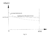
- the refrigerant distribution pressure drop in the nozzles 2 is larger than that in the openings in the conventional distributing tube, such that a pressure difference between the refrigerant inlet and the first nozzle 2 (for example, the leftmost nozzle in Fig. 1 ) is substantially identical with a pressure difference between the refrigerant inlet and the last nozzle 2(for example, the right most nozzle in Fig. 1 ). Therefore, the refrigerant distribution along the length direction of the distributing tube 1 is more uniform, as shown in Fig.
- the abscissas s represent a distance from each opening in the conventional distributing tube to the refrigerant inlet and a distance from each nozzle 2 in the refrigerant distributing device according to embodiments of the present disclosure to the refrigerant inlet
- the ordinates m represent a refrigerant flow rate in each opening and a refrigerant flow rate in each nozzle 2.
- the plurality of nozzles 2 are disposed on the distributing tube 1 along the length direction (i.e. the left and right direction in Fig. 1 ) of the distributing tube 1, and arranged on the distributing tube 1 in a straight line.
- the distributing tube 1 is formed with a plurality of mounting holes 11, and each nozzle 2 is fitted and mounted in one mounting hole 11.
- each nozzle 2 is cylindrical
- the through hole 21 is a circular hole and passes through an inner end surface (e.g. the lower end surface in Fig. 1 ) and an outer end surface (e.g. the upper end surface in Fig. 1 ) of the nozzle 2.
- a length of the through hole 21 is 0.125-250 times as large as a hydraulic diameter of the through hole 21. It should be noted that if the length of the through hole 21 of the nozzle 2 is too large, the flow resistance of the refrigerant in the nozzle 2 will be increased; and if the length of the through hole 21 of the nozzle 2 is too small, the pumping effect will be weakened. Therefore, it has been found by the applicant through lots of efforts and experiments that the balance between reducing the resistance and maintaining the pumping effect may be achieved by controlling the length of the through hole 21 to be 0.125-250 times as large as the hydraulic diameter of the through hole 21.
- an outer end (i.e. the upper end in Fig. 1 ) of the through hole 21 has an enlarged segment 22, thus facilitating the machining of the through hole 21.
- the plurality of nozzles 2 are spaced apart from each other at equal intervals in the length direction of the distributing tube 1.
- the present disclosure is not limited to this.
- the plurality of nozzles 2 may be spaced apart from each other at unequal intervals.
- an axial direction of the through hole 21 is consistent with an axial direction of the nozzle 2.
- an inner end (i.e. the end of each nozzle 2 close to the distributing tube 1) of each nozzle 2 is extended into the interior of the distributing tube 1 by a predetermined length. Because the nozzle 2 is inserted into the interior of the distributing tube 1, the refrigerant is agitated when flowing in the distributing tube 1 along the axial direction of the distributing tube 1, and the gaseous refrigerant and the liquid refrigerant are separated from and then remixed with each other continuously, such that the gaseous refrigerant and the liquid refrigerant may be still mixed uniformly when flowing to a region in the distributing tube 1 away from the refrigerant inlet of the distributing tube 1.
- the inner end of each nozzle 2 is flush with the inner wall surface or the outer wall surface of the distributing tube 1.
- the through hole 21 passes through the inner end surface and the outer end surface of the nozzle 2, and the axial direction of the through hole 21 is parallel to the axial direction of the nozzle 2.
- the distributing tube 1 is a circular tube, a ratio H / D of a length H of the through hole 21 to a hydraulic diameter D of the distributing tube 1 is in a range of 0.027 to 25, and a ratio H / L of the length H of the through hole 21 to a length L of the distributing tube 1 is in a range of 3 .3 ⁇ 10 -4 to 0.125.
- ⁇ ⁇ P ⁇ 1 / d ⁇ ⁇ ⁇ 2 / 2
- the resistance in a single nozzle is:
- ⁇ ⁇ P nozzle ⁇ 1 H / d ⁇ ⁇ ⁇ 2 i / 2
- the frictional resistance in the distributing tube is:
- ⁇ ⁇ P tube ⁇ 2 L / D ⁇ ⁇ ⁇ 2 / 2 when ⁇ P nozzle is larger than ⁇ P tube
- the flow rate distribution between individual nozzles 2 of the distributing tube 1 may be optimized.
- H 1-25 millimeters
- d 0.1-8 millimeters
- D 1-36 millimeters
- L 0.2-3 meters.
- the distributing tube 1 has a circular cross section, and the through hole 21 in the nozzle 2 is a circular hole (i.e. the through hole has a circular cross section).
- the present disclosure is not limited to this.
- the distributing tube 1 may have a rectangular cross section, and the cross section of the through hole 21 may have a square shape or any other suitable shape.
- the nozzle 2 is cylindrical, the through hole 21 has a circular cross section, the through hole 21 passes through an inner end surface (i.e., a lower end surface in Fig. 4 ) and an outer end surface (i.e., an upper end surface in Fig. 4 ) of the nozzle 2, and the axial direction of the through hole 21 is inclined at a predetermined angle ⁇ of, for example, about 0-90 degrees, preferably 0-60 degrees, relative to the axial direction of the nozzle 2.
- the length of the through hole 21 may be increased without changing the length of the nozzle 2. Therefore, the length of the refrigerant flow passage may be increased so as to enhance the mixing effect of the gaseous refrigerant and the liquid refrigerant, and the direction of the refrigerant flow passage may be changed, so that the refrigerant is ejected out of the distributing tube 1 at a particular angle so as to improve the distribution effect.
- the nozzle 2 is cylindrical
- the through hole 21 passes through an inner end surface and an outer end surface of the nozzle 2
- the through hole 21 has a cross-shaped cross section.
- the present disclosure is not limited to this.
- the through hole 21 may have a rectangular cross section. Since the through hole 21 has a non-circular cross section, the pumping effect and the ejection effect may be further enhanced, and the gas-liquid separation may be eliminated.
- each nozzle 2 is extended into the interior of the distributing tube 1 by a predetermined length, and the inner end of the each nozzle 2 is formed with a bent portion.
- the nozzle 2 may be of a bent cylinder.
- An angle ⁇ between the bent portion and the main body of the nozzle 2 may be in a range of about 45 degrees to 180 degrees.
- the through hole 21 comprises a first through hole segment 212 extending in a radial direction of the nozzle 2 and a second through hole segment 211 extending in an axial direction of the nozzle 2.
- the inner end (the lower end in Fig. 12 ) of the second through hole segment 211 is communicated with the interior of the distributing tube 1, and the outer end (the upper end in Fig. 12 ) of the second through hole segment 211 is closed.
- the first through hole segment 212 communicates the second through hole segment 211 with the exterior of the distributing tube 1.
- first through hole segment 212 is communicated with the second through hole segment 211, and the outer end of the first through hole segment 212 is communicated with the exterior of the distributing tube 1.
- a plurality of the first through hole segments 212 for example, 2-12 first through hole segments 212, are formed and arranged in the circumferential direction of the second through hole segment 211.
- the refrigerant Since the first through hole segment 212 is extended in the radial direction of the nozzle 2, the refrigerant is easy to control to be ejected out of the nozzle 2 along various radial directions of the nozzle 2, but may not be ejected along the radial direction of the distributing tube 1, thus improving the distribution uniformity of the refrigerant in the exterior of the distributing tube 1. Therefore, the refrigerant may be distributed in the exterior of the distributing tube 1 more uniformly.
- the through hole 21 comprises a plurality of first through hole segments 212 and a second through hole segment 211 extending in an axial direction of the nozzle 2.
- the inner end of the second through hole segment 211 is communicated with the interior of the distributing tube 1, and the outer end of the second through hole segment 211 is closed.
- the first through hole segments 212 communicate the second through hole segment 211 with the exterior of the distributing tube 1.
- the first through hole segments 212 and the second through hole segment 211 have circular cross sections, and the axial direction of the first through hole segment 212 is deviated from the radial direction of the nozzle 2, for example, the axial direction of the first through hole segment 212 is consistent with a tangential direction of the second through hole segment 211. Therefore, the refrigerant passing through the first through hole segment 212 is ejected along a direction deviated from the radial direction of the nozzle 2, and consequently the rotation of the refrigerant after being ejected into the second through hole segment 212 is enhanced, thus improving the distribution uniformity of the refrigerant in the exterior of the distributing tube 1. Therefore, the gaseous refrigerant and the liquid refrigerant may be distributed in the exterior of the distributing tube 1 more uniformly.
- the through hole 21 comprises a first through hole segment 212 and a second through hole segment 211 extending in an axial direction of the nozzle 2.
- the first through hole segment 212 and the second through hole segment 211 have rectangular cross sections.
- a plurality of first through hole segments 212 may be formed, and extended in the radial direction of the nozzle 2 or a direction deviated from the radial direction of the nozzle 2.
- the refrigerant distributing device will be described below with reference to Figs. 21-23 .
- the plurality of nozzles 2 are spirally arranged in the length direction of the distributing tube 1. Therefore, the gaseous refrigerant and the liquid refrigerant may be spirally ejected along the length direction of the distributing tube 1, so that the gaseous refrigerant and the liquid refrigerant may be uniformly distributed in the exterior of the distributing tube 1.
- the plurality of nozzles 2 are arranged in one row.
- the plurality of nozzles 2 may be arranged in a plurality of rows in a circumferential direction of the distributing tube 1, and the nozzle 2 in each row may be arranged spirally or linearly.
- the nozzles 2 are cylindrical. However, the present disclosure is not limited to this.
- the nozzles 2 may be of a prism having a rectangular cross section or a cross section of other shapes.
- the nozzles 2 may be manufactured separately and mounted onto the distributing tube 1.
- the nozzles 2 and the distributing tube 1 may be integrally manufactured, for example, the nozzles 2 and the distributing tube 1 are integrally cast.
- the nozzles 2 are disposed on the distributing tube 1, the distribution effect may be improved, and the separation of the gaseous refrigerant and the liquid refrigerant may be reduced, thus improving the heat exchange effect.
- the heat exchanger according to an embodiment of the present disclosure will be described below with reference to Figs. 24-25 .
- the heat exchanger according to an embodiment of the present disclosure comprises an inlet header 100, an outlet header 200, a plurality of heat exchange tubes 300, a plurality of fins 400, and a refrigerant distributing device described with reference to embodiments of the present disclosure.
- each heat exchange tube 300 Two ends of each heat exchange tube 300 are connected with the inlet header 100 and the outlet header 200 respectively to communicate the inlet header 100 and the outlet header 200.
- the plurality of fins 400 are disposed between adjacent heat exchange tubes 300 respectively.
- the refrigerant distributing device is disposed in the inlet header 100.
- one end i.e., a right end in Fig. 24
- the distributing tube 1 of the refrigerant distributing device is inserted into the inlet header 100 along a length direction of the inlet header 100.
- the one end of the distributing tube 1 may be closed by a separate end cap or the right end wall of the inlet header 100.
- the other end i.e., a left end in Fig.
- the refrigerant distribution effect and the heat exchange performance are good.
- the refrigerant distributing device may also be disposed in the outlet header 200.
- the refrigerant distributing device is used as a refrigerant collecting device.
- the refrigerant distributing device according to an embodiment of the present disclosure may be disposed in the inlet header 100 and the outlet header 200 simultaneously.
- the refrigerant distributing device and the heat exchanger are capable of improving the flow rate balance. Since the flow resistance is increased by means of the through holes of the nozzles, the pressure difference between individual nozzles may be balanced, and the pressure imbalance between individual nozzles may be reduced largely, so that the refrigerant flow rate along the length direction of the distributing tube may be more balanced.
- the refrigerant distributing device and the heat exchanger are capable of controlling and adjusting the direction of the refrigerant.
- the gaseous refrigerant and the liquid refrigerant may be ejected out of the nozzles not only along the radial direction of the distributing tube, but also along the axial direction, the circumferential direction or other directions of the distributing tube, so that the refrigerant distribution uniformity in the exterior of the distributing tube may be improved largely.
Landscapes
- Engineering & Computer Science (AREA)
- Physics & Mathematics (AREA)
- Thermal Sciences (AREA)
- Mechanical Engineering (AREA)
- General Engineering & Computer Science (AREA)
- Geometry (AREA)
- Heat-Exchange Devices With Radiators And Conduit Assemblies (AREA)
- Details Of Heat-Exchange And Heat-Transfer (AREA)
Abstract
Description
- The present disclosure relates to a refrigerant distributing device of a heat exchanger and a heat exchanger comprising the same.
- A distributing tube is generally inserted into a header of the heat exchanger in order to ensure uniform distribution of a refrigerant in the heat exchange tubes of the heat exchanger. The distributing tube is formed with openings through which the refrigerant enters into the header from the distributing tube so as to be distributed to individual heat exchange tubes.
- The conventional distributing tube has disadvantages. For example, in use, a refrigerant at an inlet of a heat exchanger is in a gaseous-liquid two phase state, and the density difference between the gaseous refrigerant and the liquid refrigerant is large, which may cause gas-liquid separation, thus affecting the refrigerant distribution uniformity. The gaseous-liquid refrigerant directly flows into the header through openings of the distributing tube, and the gas-liquid separation tends to occur when the gaseous-liquid refrigerant leaves the openings, thus affecting the refrigerant distribution uniformity. Pressures at individual openings are not balanced in a refrigerant flow direction, thus causing flow rate imbalance between individual openings in a length direction of the distributing tube. The machining of the openings is difficult due to the increased amount or different types of the openings, and the distributing tube is difficult to clean due to the burrs on machining surfaces of the openings.
- The present disclosure seek to solve at least one of the problems existing in the prior art.
- Accordingly, an object of a first aspect of the present disclosure is to provide a refrigerant distributing device capable of improving the refrigerant distribution uniformity.
- An object of a second aspect of the present disclosure is to provide a heat exchanger comprising the refrigerant distributing device according to the first aspect of the present disclosure which may have improved heat exchange performance.
- Embodiments of the first aspect of the present disclosure provide a refrigerant distributing device comprising: a distributing tube defining a first end and a second end in a length direction thereof; and a plurality of nozzles disposed on the distributing tube along the length direction of the distributing tube, each nozzle having a predetermined length and being formed with a through hole communicating an interior of the distributing tube and an exterior of the distributing tube.
- The refrigerant distributing device according to embodiments of the present disclosure is capable of improving the flow rate balance. The flow resistance is increased because of the nozzles, the pressures at individual nozzles may be balanced, and the pressure imbalance between individual nozzles may be reduced greatly, so that the refrigerant flow rate along the length direction of the distributing tube is more balanced.
- The refrigerant distributing device according to embodiments of the present disclosure can control and adjust the flow direction of the refrigerant. The gaseous-liquid refrigerant may be ejected out of the nozzles along the radial direction, the axial direction, the circumferential direction and other directions of the distributing tube, so that the refrigerant distribution uniformity in the exterior of the distributing tube is improved greatly.
- In some embodiments, the plurality of nozzles are arranged in a plurality of rows in a circumferential direction of the distributing tube, and the nozzles in each row are arranged spirally.
- In some embodiments, the through hole is a circular hole and passes through inner and outer end surfaces of the nozzle, and a length of the through hole is 0.125-250 times as large as a hydraulic diameter of the through hole.
- In some embodiments, the through hole passes through inner and outer end surfaces of the nozzle, and an axial direction of the through hole is inclined relative to an axial direction of the nozzle.
- In some embodiments, the through hole has a rectangular or cross-shaped cross section.
- In some embodiments, the through hole comprises a first through hole segment extending in a radial direction of the nozzle and a second through hole segment extending in an axial direction of the nozzle, an inner end of the second through hole segment is communicated with the interior of the distributing tube, and an outer end of the second through hole segment is closed, the first through hole segment communicates the second through hole segment with the exterior of the distributing tube.
- In some embodiments, a plurality of the first through hole segments are formed and arranged in a circumferential direction of the second through hole segment.
- In some embodiments, the through hole comprises a first through hole segment and a second through hole segment extending in an axial direction of the nozzle, an inner end of the second through hole segment is communicated with the interior of the distributing tube, and an outer end of the second through hole segment is closed, the first through hole segment communicates the second through hole segment with the exterior of the distributing tube, and an axial direction of the first through hole segment is deviated from a radial direction of the nozzle.
- In some embodiments, an inner end of each nozzle is extended into the interior of the distributing tube by a predetermined length.
- In some embodiments, the inner end of the each nozzle is formed with a bent portion.
- In some embodiments, an inner end of each nozzle is flush with an inner wall surface or an outer wall surface of the distributing tube.
- In some embodiments, the through hole passes through inner and outer end surfaces of the nozzle, an axial direction of the through hole is parallel to an axial direction of the nozzle, the distributing tube has a circular cross-section, a ratio H/D of a length H of the through hole to a hydraulic diameter D of the distributing tube is in a range of 0.027 to 25, and a ratio H/L of the length H of the through hole to a length L of the distributing tube is in a range of 3.3×10⁻⁴ to 0.125.
- In some embodiments, a sum of cross-sectional areas of the through holes of the nozzles is 0.01 % to 40% of a circumferential surface area of the distributing tube.
- Embodiments according to the second aspect of the present disclosure provide a heat exchanger comprising: an inlet header; an outlet header; a plurality of heat exchange tubes each having two ends connected with the inlet header and the outlet header respectively to communicate the inlet header and the outlet header; a plurality of fins disposed between adjacent heat exchange tubes respectively; and a refrigerant distributing device according to embodiments of the first aspect of the present disclosure disposed in the inlet header.
- Additional aspects and advantages of embodiments of present disclosure will be given in part in the following descriptions, become apparent in part from the following descriptions, or be learned from the practice of the embodiments of the present disclosure.
- These and other aspects and advantages of embodiments of the present disclosure will become apparent and more readily appreciated from the following descriptions made with reference to the accompanying drawings, in which:
-
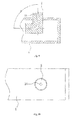
Fig. 1 is a schematic view of a refrigerant distributing device according to a first embodiment of the present disclosure; -
Fig. 2 is a top view of the refrigerant distributing device shown inFig. 1 ; -
Fig. 3 is a schematic cross-sectional view of the refrigerant distributing device shown inFig. 1 ; -
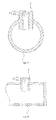
Fig. 4 is a partial sectional view of a refrigerant distributing device according to a second embodiment of the present disclosure; -
Fig. 5 is a top view of the refrigerant distributing device shown inFig. 4 ; -
Fig. 6 is a partial sectional view of a refrigerant distributing device according to a third embodiment of the present disclosure; -
Fig. 7 is a top view of the refrigerant distributing device shown inFig. 6 ; -
Fig. 8 is a schematic cross-sectional view of the refrigerant distributing device shown inFig. 6 ; -
Fig. 9 is a partial sectional view of a refrigerant distributing device according to a fourth embodiment of the present disclosure; -
Fig. 10 is a top view of the refrigerant distributing device shown inFig. 9 ; -
Fig. 11 is a schematic cross-sectional view of the refrigerant distributing device shown inFig. 9 ; -
Fig. 12 is a partial sectional view of a refrigerant distributing device according to a fifth embodiment of the present disclosure; -
Fig. 13 is a top view of the refrigerant distributing device shown inFig. 12 ; -
Fig. 14 is a schematic cross-sectional view of the refrigerant distributing device shown inFig. 12 ; -
Fig. 15 is a schematic view of a refrigerant distributing device according to a sixth embodiment of the present disclosure; -
Fig. 16 is a top view of the refrigerant distributing device shown inFig. 15 ; -
Fig. 17 is a schematic cross-sectional view of the refrigerant distributing device shown inFig. 15 ; -
Fig. 18 is a schematic view of a refrigerant distributing device according to a seventh embodiment of the present disclosure; -
Fig. 19 is a top view of the refrigerant distributing device shown inFig. 18 ; -
Fig. 20 is a schematic cross-sectional view of the refrigerant distributing device shown inFig. 18 ; -
Fig. 21 is a schematic view of a refrigerant distributing device according to an eighth embodiment of the present disclosure; -
Fig. 22 is a top view of the refrigerant distributing device shown inFig. 21 ; -
Fig. 23 is a schematic cross-sectional view of the refrigerant distributing device shown inFig. 21 ; -
Fig. 24 is a schematic view of a heat exchanger according to an embodiment of the present disclosure; -
Fig. 25 is a schematic partial cross-sectional view of an inlet header of the heat exchanger shown inFig. 24 ; and -
Fig. 26 is a graph illustrating a comparison between a refrigerant distribution effect of a refrigerant distributing device according to an embodiment of the present disclosure and a refrigerant distribution effect of a conventional distributing tube. - Reference will be made in detail to embodiments of the present disclosure. The embodiments described herein with reference to drawings are explanatory, illustrative, and used to generally understand the present disclosure. The embodiments shall not be construed to limit the present disclosure. The same or similar elements and the elements having same or similar functions are denoted by like reference numerals throughout the descriptions.
- In the specification, unless specified or limited otherwise, relative terms such as "length direction", "lateral", "axial direction", "upper", "lower", "front", "rear", "left", "right", "vertical", "horizontal", "top", "bottom", "inner", "outer", as well as derivative thereof (e.g., "horizontally", "downwardly", "upwardly", etc.) should be construed to refer to the orientation as then described or as shown in the drawings under discussion. These relative terms are for convenience of description and do not require that the present disclosure be constructed or operated in a particular orientation.
- The refrigerant distributing device according to embodiments of the present disclosure will be described below with reference to the drawings.
- As shown in
Figs. 1-23 , the refrigerant distributing device according to embodiments of the present disclosure comprises a distributingtube 1 having a first end (i.e. the left end inFig. 1 ) and a second end (i.e. the right end inFig. 1 ) in a length direction (i.e. the left and right direction inFig. 1 ) thereof. A plurality ofnozzles 2 are disposed on the distributingtube 1 along the length direction of the distributingtube 1, and eachnozzle 2 has a predetermined length and is formed with a throughhole 21 communicating an interior of the distributingtube 1 and an exterior of the distributingtube 1. Here, a person having ordinary skill in the art will appreciate that the exterior of the distributingtube 1 means an interior of a header when the refrigerant distributing device is mounted into the header of a heat exchanger. - In an example, as shown in
Fig. 1 , the first end of the distributingtube 1 is open, and the second end of the distributingtube 1 is closed. However, a person having ordinary skill in the art will appreciate that the second end of the distributingtube 1 may be open, and then closed by an end wall of the header when the refrigerant distributing device is mounted into the header of the heat exchanger. In order to facilitate description, hereinafter, the left end of the distributingtube 1 is referred as an inlet end of the distributingtube 1, that is, the left end opening of the distributingtube 1 is used as the refrigerant inlet of the distributingtube 1. - With the refrigerant distributing device according to embodiments of the present disclosure, the plurality of
nozzles 2 are mounted on the distributingtube 1 along the length direction of the distributingtube 1, the pumping effect may be generated in thenozzles 2 under the same pressure as that in the related art, such that the flow rate in thenozzles 2 is larger than that in openings of a conventional distributing tube when the hydraulic diameter of thenozzle 2 is identical with that of the opening of the conventional distributing tube. - In addition, the gaseous refrigerant and the liquid refrigerant may be mixed again when flowing in the through
holes 21 of thenozzles 2, thus further reducing the gas-liquid separation. Moreover, the throughholes 21 of thenozzles 2 may increase the length of the refrigerant ejection passage so as to increase the refrigerant distribution pressure difference, such that the refrigerant flow rate distribution is more uniform along the entire length direction of the distributingtube 1, thus improving the heat exchange performance of the heat exchanger. - By comparison to the conventional distributing tube having distributing openings formed in a wall thereof, with the refrigerant distributing device according to embodiments of the present disclosure, the
nozzles 2 each having a predetermined length are disposed on the distributingtube 1. The refrigerant flow rate Q follows a formula:
hole 21 of thenozzle 2, H is a pressure head, g is the gravity acceleration, and µ0 is a flow rate coefficient. Because the flow rate coefficient µ0 of thenozzle 2 is 0.82 and the flow rate coefficient µ 0 of the opening in the conventional distributing tube is 0.62, the flow rate in thenozzle 2 is larger than that in the opening in the conventional distributing tube when the hydraulic diameter of thenozzle 2 is identical with that of the opening in the conventional distributing tube. - In addition, with the conventional distributing tube, the refrigerant flows out of the distributing tube through individual openings formed in the wall of the distributing tube, the pressure drops in the individual openings are unequal, and a pressure difference between the refrigerant inlet and the opening furthest from the refrigerant inlet (i.e., the last opening) differs greatly from that between the refrigerant inlet and the opening nearest to the refrigerant inlet (i.e. the first opening), such that the refrigerant flow rate distribution along a length direction of the distributing tube is non-uniform, that is, the flow rate in the first opening is much larger than that in the last opening. In contrast, with the refrigerant distributing device according to embodiments of the present disclosure, because the
nozzles 2 each having a predetermined length are disposed on the distributingtube 1, the refrigerant flow passage in eachnozzle 2 is lengthened, and the refrigerant distribution pressure drop in thenozzles 2 is larger than that in the openings in the conventional distributing tube, such that a pressure difference between the refrigerant inlet and the first nozzle 2 (for example, the leftmost nozzle inFig. 1 ) is substantially identical with a pressure difference between the refrigerant inlet and the last nozzle 2(for example, the right most nozzle inFig. 1 ). Therefore, the refrigerant distribution along the length direction of the distributingtube 1 is more uniform, as shown inFig. 26 . InFig. 26 , the abscissas s represent a distance from each opening in the conventional distributing tube to the refrigerant inlet and a distance from eachnozzle 2 in the refrigerant distributing device according to embodiments of the present disclosure to the refrigerant inlet, and the ordinates m represent a refrigerant flow rate in each opening and a refrigerant flow rate in eachnozzle 2. - The refrigerant distributing device according to a first embodiment of the present disclosure will be described below with reference to
Figs. 1-3 , As shown inFigs. 1-3 , with the refrigerant distributing device according to the first embodiment of the present disclosure, the plurality ofnozzles 2 are disposed on the distributingtube 1 along the length direction (i.e. the left and right direction inFig. 1 ) of the distributingtube 1, and arranged on the distributingtube 1 in a straight line. Preferably, the distributingtube 1 is formed with a plurality of mounting holes 11, and eachnozzle 2 is fitted and mounted in one mounting hole 11. - In the embodiment shown in
Figs. 1-3 , eachnozzle 2 is cylindrical, the throughhole 21 is a circular hole and passes through an inner end surface (e.g. the lower end surface inFig. 1 ) and an outer end surface (e.g. the upper end surface inFig. 1 ) of thenozzle 2. A length of the throughhole 21 is 0.125-250 times as large as a hydraulic diameter of the throughhole 21. It should be noted that if the length of the throughhole 21 of thenozzle 2 is too large, the flow resistance of the refrigerant in thenozzle 2 will be increased; and if the length of the throughhole 21 of thenozzle 2 is too small, the pumping effect will be weakened. Therefore, it has been found by the applicant through lots of efforts and experiments that the balance between reducing the resistance and maintaining the pumping effect may be achieved by controlling the length of the throughhole 21 to be 0.125-250 times as large as the hydraulic diameter of the throughhole 21. - As shown in
Figs. 1-3 , in some specific examples, an outer end (i.e. the upper end inFig. 1 ) of the throughhole 21 has anenlarged segment 22, thus facilitating the machining of the throughhole 21. - As shown in
Figs. 1-2 , in some examples, the plurality ofnozzles 2 are spaced apart from each other at equal intervals in the length direction of the distributingtube 1. However, the present disclosure is not limited to this. For example, the plurality ofnozzles 2 may be spaced apart from each other at unequal intervals. - As shown in
Fig. 3 , in one example, an axial direction of the throughhole 21 is consistent with an axial direction of thenozzle 2. - In other examples, an inner end (i.e. the end of each
nozzle 2 close to the distributing tube 1) of eachnozzle 2 is extended into the interior of the distributingtube 1 by a predetermined length. Because thenozzle 2 is inserted into the interior of the distributingtube 1, the refrigerant is agitated when flowing in the distributingtube 1 along the axial direction of the distributingtube 1, and the gaseous refrigerant and the liquid refrigerant are separated from and then remixed with each other continuously, such that the gaseous refrigerant and the liquid refrigerant may be still mixed uniformly when flowing to a region in the distributingtube 1 away from the refrigerant inlet of the distributingtube 1. Alternatively, the inner end of eachnozzle 2 is flush with the inner wall surface or the outer wall surface of the distributingtube 1. - In some embodiments, the through
hole 21 passes through the inner end surface and the outer end surface of thenozzle 2, and the axial direction of the throughhole 21 is parallel to the axial direction of thenozzle 2. The distributingtube 1 is a circular tube, a ratio H/D of a length H of the throughhole 21 to a hydraulic diameter D of the distributingtube 1 is in a range of 0.027 to 25, and a ratio H/L of the length H of the throughhole 21 to a length L of the distributingtube 1 is in a range of 3 .3×10-4 to 0.125. - According to some embodiments of the present disclosure, if the local pressure drop is not considered, according to a formula of the frictional resistance (i.e. frictional drag) in the distributing tube:

the resistance in a single nozzle is:
the frictional resistance in the distributing tube is:
when ΔP nozzle is larger than ΔP tube, the optimization of the flow rate in the nozzle may be realized. - Therefore, when the ratio H/D of the length H of the through
hole 21 to the hydraulic diameter D of the distributingtube 1 is in a range of 0.027 to 25 and the ratio H/L of the length H of the throughhole 21 to the length L of the distributingtube 1 is in a range of 3.3×10⁻⁴ to 0.125, the flow rate distribution betweenindividual nozzles 2 of the distributingtube 1 may be optimized. For example, in a specific example, H= 1-25 millimeters, d = 0.1-8 millimeters, D = 1-36 millimeters, L = 0.2-3 meters. - Likewise, based on the above analysis, when a sum of cross-sectional areas of the through
holes 21 of thenozzle 2 is 0.01% to 40% of a circumferential surface area of the distributingtube 1, the flow rate distribution betweenindividual nozzles 2 of the distributingtube 1 may be optimized. - In the embodiment shown in
Figs. 1-3 , the distributingtube 1 has a circular cross section, and the throughhole 21 in thenozzle 2 is a circular hole (i.e. the through hole has a circular cross section). However, the present disclosure is not limited to this. For example, in other embodiments, the distributingtube 1 may have a rectangular cross section, and the cross section of the throughhole 21 may have a square shape or any other suitable shape. - The refrigerant distributing device according to a second embodiment of the present disclosure will be described below with reference to
Figs. 4-5 . In the second embodiment shown inFigs. 4-5 , thenozzle 2 is cylindrical, the throughhole 21 has a circular cross section, the throughhole 21 passes through an inner end surface (i.e., a lower end surface inFig. 4 ) and an outer end surface (i.e., an upper end surface inFig. 4 ) of thenozzle 2, and the axial direction of the throughhole 21 is inclined at a predetermined angle α of, for example, about 0-90 degrees, preferably 0-60 degrees, relative to the axial direction of thenozzle 2. By controlling the axial direction of the throughhole 21 to be inclined relative to the axial direction of thenozzle 2, the length of the throughhole 21 may be increased without changing the length of thenozzle 2. Therefore, the length of the refrigerant flow passage may be increased so as to enhance the mixing effect of the gaseous refrigerant and the liquid refrigerant, and the direction of the refrigerant flow passage may be changed, so that the refrigerant is ejected out of the distributingtube 1 at a particular angle so as to improve the distribution effect. - The refrigerant distributing device according to a third embodiment of the present disclosure will be described below with reference to
Figs. 6-8 . In the third embodiment shown inFigs. 6-8 , thenozzle 2 is cylindrical, the throughhole 21 passes through an inner end surface and an outer end surface of thenozzle 2, and the throughhole 21 has a cross-shaped cross section. However, the present disclosure is not limited to this. For example, the throughhole 21 may have a rectangular cross section. Since the throughhole 21 has a non-circular cross section, the pumping effect and the ejection effect may be further enhanced, and the gas-liquid separation may be eliminated. - The refrigerant distributing device according to a fourth embodiment of the present disclosure will be described below with reference to
Figs. 9-11 . In the fourth embodiment shown inFigs. 9-11 , the inner end of eachnozzle 2 is extended into the interior of the distributingtube 1 by a predetermined length, and the inner end of the eachnozzle 2 is formed with a bent portion. In other words, thenozzle 2 may be of a bent cylinder. An angle β between the bent portion and the main body of thenozzle 2 may be in a range of about 45 degrees to 180 degrees. By forming the bent portion at the inner end of thenozzle 2, the gaseous refrigerant and the liquid refrigerant may be guided, and the agitation effect on the refrigerant in the distributingtube 1 may be further enhanced. - The refrigerant distributing device according to a fifth embodiment of the present disclosure will be described below with reference to
Figs. 12-14 . In the fifth embodiment shown inFigs. 12-14 , the throughhole 21 comprises a first throughhole segment 212 extending in a radial direction of thenozzle 2 and a second throughhole segment 211 extending in an axial direction of thenozzle 2. The inner end (the lower end inFig. 12 ) of the second throughhole segment 211 is communicated with the interior of the distributingtube 1, and the outer end (the upper end inFig. 12 ) of the second throughhole segment 211 is closed. The first throughhole segment 212 communicates the second throughhole segment 211 with the exterior of the distributingtube 1. In other words, the inner end of the first throughhole segment 212 is communicated with the second throughhole segment 211, and the outer end of the first throughhole segment 212 is communicated with the exterior of the distributingtube 1. In a specific example, a plurality of the first throughhole segments 212, for example, 2-12 first throughhole segments 212, are formed and arranged in the circumferential direction of the second throughhole segment 211. Since the first throughhole segment 212 is extended in the radial direction of thenozzle 2, the refrigerant is easy to control to be ejected out of thenozzle 2 along various radial directions of thenozzle 2, but may not be ejected along the radial direction of the distributingtube 1, thus improving the distribution uniformity of the refrigerant in the exterior of the distributingtube 1. Therefore, the refrigerant may be distributed in the exterior of the distributingtube 1 more uniformly. - The refrigerant distributing device according to a sixth embodiment of the present disclosure will be described below with reference to
Figs. 15-17 . In the sixth embodiment shown inFigs. 15-17 , the throughhole 21 comprises a plurality of first throughhole segments 212 and a second throughhole segment 211 extending in an axial direction of thenozzle 2. The inner end of the second throughhole segment 211 is communicated with the interior of the distributingtube 1, and the outer end of the second throughhole segment 211 is closed. The first throughhole segments 212 communicate the second throughhole segment 211 with the exterior of the distributingtube 1. In the embodiment shown inFigs. 15-17 , the first throughhole segments 212 and the second throughhole segment 211 have circular cross sections, and the axial direction of the first throughhole segment 212 is deviated from the radial direction of thenozzle 2, for example, the axial direction of the first throughhole segment 212 is consistent with a tangential direction of the second throughhole segment 211. Therefore, the refrigerant passing through the first throughhole segment 212 is ejected along a direction deviated from the radial direction of thenozzle 2, and consequently the rotation of the refrigerant after being ejected into the second throughhole segment 212 is enhanced, thus improving the distribution uniformity of the refrigerant in the exterior of the distributingtube 1. Therefore, the gaseous refrigerant and the liquid refrigerant may be distributed in the exterior of the distributingtube 1 more uniformly. - The refrigerant distributing device according to a seventh embodiment of the present disclosure will be described below with reference to
Figs. 18-20 . In the seventh embodiment shown inFigs. 18-20 , the throughhole 21 comprises a first throughhole segment 212 and a second throughhole segment 211 extending in an axial direction of thenozzle 2. The first throughhole segment 212 and the second throughhole segment 211 have rectangular cross sections. Alternatively, a plurality of first throughhole segments 212 may be formed, and extended in the radial direction of thenozzle 2 or a direction deviated from the radial direction of thenozzle 2. - The refrigerant distributing device according to an eighth embodiment of the present disclosure will be described below with reference to
Figs. 21-23 . In the eighth embodiment shown inFigs. 21-23 , the plurality ofnozzles 2 are spirally arranged in the length direction of the distributingtube 1. Therefore, the gaseous refrigerant and the liquid refrigerant may be spirally ejected along the length direction of the distributingtube 1, so that the gaseous refrigerant and the liquid refrigerant may be uniformly distributed in the exterior of the distributingtube 1. - In the above embodiments, the plurality of
nozzles 2 are arranged in one row. However, it should be appreciated that the plurality ofnozzles 2 may be arranged in a plurality of rows in a circumferential direction of the distributingtube 1, and thenozzle 2 in each row may be arranged spirally or linearly. - In the above embodiments, the
nozzles 2 are cylindrical. However, the present disclosure is not limited to this. For example, thenozzles 2 may be of a prism having a rectangular cross section or a cross section of other shapes. - In some embodiments, the
nozzles 2 may be manufactured separately and mounted onto the distributingtube 1. Alternatively, thenozzles 2 and the distributingtube 1 may be integrally manufactured, for example, thenozzles 2 and the distributingtube 1 are integrally cast. - With the refrigerant distributing device according to embodiments of the present disclosure, because the
nozzles 2 are disposed on the distributingtube 1, the distribution effect may be improved, and the separation of the gaseous refrigerant and the liquid refrigerant may be reduced, thus improving the heat exchange effect. - The heat exchanger according to an embodiment of the present disclosure will be described below with reference to
Figs. 24-25 . As shown inFigs. 24-25 , the heat exchanger according to an embodiment of the present disclosure comprises aninlet header 100, anoutlet header 200, a plurality ofheat exchange tubes 300, a plurality offins 400, and a refrigerant distributing device described with reference to embodiments of the present disclosure. - Two ends of each
heat exchange tube 300 are connected with theinlet header 100 and theoutlet header 200 respectively to communicate theinlet header 100 and theoutlet header 200. The plurality offins 400 are disposed between adjacentheat exchange tubes 300 respectively. The refrigerant distributing device is disposed in theinlet header 100. As shown inFigs. 24-25 , one end (i.e., a right end inFig. 24 ) of the distributingtube 1 of the refrigerant distributing device is inserted into theinlet header 100 along a length direction of theinlet header 100. For example, the one end of the distributingtube 1 may be closed by a separate end cap or the right end wall of theinlet header 100. The other end (i.e., a left end inFig. 24 ) of the distributingtube 1 may be exposed out of theinlet header 100 and used as a refrigerant inlet of the heat exchanger. With the heat exchanger according to an embodiment of the present disclosure, the refrigerant distribution effect and the heat exchange performance are good. - It should be appreciated that, in some embodiments, the refrigerant distributing device according to an embodiment of the present disclosure may also be disposed in the
outlet header 200. In this case, the refrigerant distributing device is used as a refrigerant collecting device. Alternatively, the refrigerant distributing device according to an embodiment of the present disclosure may be disposed in theinlet header 100 and theoutlet header 200 simultaneously. - In conclusion, the refrigerant distributing device and the heat exchanger according to embodiments of the present disclosure are capable of improving the flow rate balance. Since the flow resistance is increased by means of the through holes of the nozzles, the pressure difference between individual nozzles may be balanced, and the pressure imbalance between individual nozzles may be reduced largely, so that the refrigerant flow rate along the length direction of the distributing tube may be more balanced.
- The refrigerant distributing device and the heat exchanger according to embodiments of the present disclosure are capable of controlling and adjusting the direction of the refrigerant. The gaseous refrigerant and the liquid refrigerant may be ejected out of the nozzles not only along the radial direction of the distributing tube, but also along the axial direction, the circumferential direction or other directions of the distributing tube, so that the refrigerant distribution uniformity in the exterior of the distributing tube may be improved largely.
- Reference throughout this specification to "a first embodiment", "a second embodiment", "some embodiments", "an example", "a specific example", or "some examples" means that a particular feature, structure, material, or characteristic described in connection with the embodiment or example is included in at least one embodiment or example of the present disclosure. Thus, the appearances of the above phrases in various places throughout this specification are not necessarily referring to the same embodiment or example of the present disclosure. Furthermore, the particular features, structures, materials, or characteristics may be combined in any suitable manner in one or more embodiments or examples.
- Although explanatory embodiments have been shown and described, it would be appreciated by those skilled in the art that the above embodiments can not be construed to limit the present disclosure, and changes, alternatives, and modifications can be made in the embodiments without departing from spirit, principles and scope of the present disclosure.
Claims (14)
- A refrigerant distributing device, comprising:a distributing tube defining a first end and a second end in a length direction thereof; anda plurality of nozzles disposed on the distributing tube along the length direction of the distributing tube, each nozzle having a predetermined length and being formed with a through hole communicating an interior of the distributing tube and an exterior of the distributing tube.
- The refrigerant distributing device according to claim 1, wherein the plurality of nozzles are arranged in a plurality of rows in a circumferential direction of the distributing tube, and the nozzles in each row are arranged spirally.
- The refrigerant distributing device according to claim 1, wherein the through hole is a circular hole and passes through inner and outer end surfaces of the nozzle, and a length of the through hole is 0.125-250 times as large as a hydraulic diameter of the through hole.
- The refrigerant distributing device according to claim 1, wherein the through hole passes through inner and outer end surfaces of the nozzle, and an axial direction of the through hole is inclined relative to an axial direction of the nozzle.
- The refrigerant distributing device according to claim 1, wherein the through hole has a rectangular or cross-shaped cross section.
- The refrigerant distributing device according to claim 1, wherein the through hole comprises a first through hole segment extending in a radial direction of the nozzle and a second through hole segment extending in an axial direction of the nozzle,
wherein an inner end of the second through hole segment is communicated with the interior of the distributing tube, and an outer end of the second through hole segment is closed,
wherein the first through hole segment communicates the second through hole segment with the exterior of the distributing tube. - The refrigerant distributing device according to claim 6, wherein a plurality of the first through hole segments are formed and arranged in a circumferential direction of the second through hole segment.
- The refrigerant distributing device according to claim 1, wherein the through hole comprises a first through hole segment and a second through hole segment extending in an axial direction of the nozzle,
wherein an inner end of the second through hole segment is communicated with the interior of the distributing tube, and an outer end of the second through hole segment is closed,
wherein the first through hole segment communicates the second through hole segment with the exterior of the distributing tube, and an axial direction of the first through hole segment is deviated from a radial direction of the nozzle. - The refrigerant distributing device according to any one of claims 1-8, wherein an inner end of each nozzle is extended into the interior of the distributing tube by a predetermined length.
- The refrigerant distributing device according to claim 9, wherein the inner end of the nozzle is formed with a bent portion.
- The refrigerant distributing device according to any one of claims 1-8, wherein an inner end of each nozzle is flush with an inner wall surface or an outer wall surface of the distributing tube.
- The refrigerant distributing device according to claim 1, wherein the through hole passes through inner and outer end surfaces of the nozzle,
wherein an axial direction of the through hole is parallel to an axial direction of the nozzle, the distributing tube has a circular cross-section,
wherein a ratio H/D of a length H of the through hole to a hydraulic diameter D of the distributing tube is in a range of 0.027 to 25, and a ratio H/L of the length H of the through hole to a length L of the distributing tube is in a range of 3.3×10⁻⁴ to 0.125. - The refrigerant distributing device according to claim 1, wherein a sum of cross-sectional areas of the through holes of the nozzles is 0.01% to 40% of a circumferential surface area of the distributing tube.
- A heat exchanger, comprising:an inlet header;an outlet header;a plurality of heat exchange tubes each having two ends connected with the inlet header and the outlet header respectively to communicate the inlet header and the outlet header;a plurality of fins disposed between adjacent heat exchange tubes respectively; anda refrigerant distributing device according to any one of claims 1-13 disposed in the inlet header.
Applications Claiming Priority (2)
| Application Number | Priority Date | Filing Date | Title |
|---|---|---|---|
| CN201010590176.9A CN102564204B (en) | 2010-12-08 | 2010-12-08 | Refrigerant distributing device and the heat exchanger with it |
| PCT/CN2011/073846 WO2012075772A1 (en) | 2010-12-08 | 2011-05-09 | Refrigerant distributing device and heat exchanger with the same |
Publications (3)
| Publication Number | Publication Date |
|---|---|
| EP2650635A1 true EP2650635A1 (en) | 2013-10-16 |
| EP2650635A4 EP2650635A4 (en) | 2017-10-11 |
| EP2650635B1 EP2650635B1 (en) | 2023-05-10 |
Family
ID=46206575
Family Applications (1)
| Application Number | Title | Priority Date | Filing Date |
|---|---|---|---|
| EP11846143.3A Active EP2650635B1 (en) | 2010-12-08 | 2011-05-09 | Refrigerant distributing device and heat exchanger with the same |
Country Status (5)
| Country | Link |
|---|---|
| US (1) | US20130312944A1 (en) |
| EP (1) | EP2650635B1 (en) |
| JP (1) | JP6114995B2 (en) |
| CN (1) | CN102564204B (en) |
| WO (1) | WO2012075772A1 (en) |
Families Citing this family (17)
| Publication number | Priority date | Publication date | Assignee | Title |
|---|---|---|---|---|
| CN103868287B (en) * | 2012-12-18 | 2016-02-03 | 珠海格力电器股份有限公司 | Refrigerant distributor and heat exchanger using same |
| CN103486896B (en) | 2013-07-30 | 2015-05-27 | 杭州三花微通道换热器有限公司 | Manifold assembly and heat exchanger with same |
| CN104344607B (en) * | 2013-08-08 | 2018-07-06 | 浙江盾安热工科技有限公司 | A kind of heat exchanger |
| CN103604254B (en) * | 2013-11-12 | 2016-07-06 | 清华大学 | A kind of built-in biphase gas and liquid flow flow dividing structure |
| CN103868398B (en) * | 2014-02-26 | 2016-08-31 | 美的集团股份有限公司 | Header and there is the parallel-flow heat exchanger of this header |
| US9915456B2 (en) | 2015-06-03 | 2018-03-13 | Mitsubishi Electric Research Laboratories, Inc. | System and method for controlling vapor compression systems |
| KR102151217B1 (en) * | 2015-12-07 | 2020-09-02 | 에스트라오토모티브시스템 주식회사 | Refrigerant distributing pipe of evaporator for air conditioner |
| JP6850058B2 (en) * | 2016-07-12 | 2021-03-31 | マーレベーアサーマルシステムズジャパン株式会社 | Capacitor |
| WO2018047511A1 (en) * | 2016-09-12 | 2018-03-15 | 三菱電機株式会社 | Heat exchanger and air-conditioner |
| EP3548824B1 (en) * | 2016-11-30 | 2023-03-29 | Valeo Systemes Thermiques | Device for homogenising the distribution of a refrigerant inside tubes of a heat exchanger constituting a refrigerant circuit |
| CN110940220B (en) * | 2018-09-25 | 2022-03-01 | 丹佛斯有限公司 | Distribution tube assembly for heat exchanger and header assembly and heat exchanger having the same |
| DE102019207799A1 (en) * | 2019-05-28 | 2020-12-03 | Mahle International Gmbh | Immersion pipe for refrigerant distribution in a chiller |
| EP3757498A1 (en) * | 2019-06-26 | 2020-12-30 | Valeo Autosystemy SP. Z.O.O. | Heat exchanger |
| CN110778695A (en) * | 2019-12-10 | 2020-02-11 | 南京高速齿轮制造有限公司 | Gear box sliding ring oil way device |
| CN114061178B (en) * | 2020-07-29 | 2025-07-25 | 约克广州空调冷冻设备有限公司 | Evaporator |
| WO2025063267A1 (en) * | 2023-09-21 | 2025-03-27 | 三菱重工サーマルシステムズ株式会社 | Heat exchanger |
| CN117781065A (en) * | 2023-12-12 | 2024-03-29 | 新地能源工程技术有限公司 | A waterway distributor for small skid-mounted equipment |
Family Cites Families (35)
| Publication number | Priority date | Publication date | Assignee | Title |
|---|---|---|---|---|
| JPS48114352U (en) * | 1972-04-03 | 1973-12-27 | ||
| JPS5062742U (en) * | 1973-10-03 | 1975-06-07 | ||
| US4058262A (en) * | 1976-02-13 | 1977-11-15 | Bete Fog Nozzle Inc. | Fluid spray for generating rectangular coverage |
| US4265840A (en) * | 1978-09-25 | 1981-05-05 | Baehler Paul | Vapor distributor pipe for air humidifier |
| GB2046421B (en) * | 1979-02-20 | 1983-05-05 | Linde Ag | Spraying system for delivering a liquid cryogenic coolant into an insulated freezing chamber |
| US4568022A (en) * | 1980-04-04 | 1986-02-04 | Baltimore Aircoil Company, Inc. | Spray nozzle |
| US4384873A (en) * | 1982-02-10 | 1983-05-24 | Herrmidifier Company, Inc. | Central steam humidifier |
| CN2034087U (en) * | 1988-06-24 | 1989-03-15 | 国家机械工业委员会西安重型机械研究所 | Nozzle with fuel swirler |
| US5291943A (en) * | 1992-12-29 | 1994-03-08 | The Regents Of The University Of California | Heat transfer enhancement using tangential injection |
| JPH073737U (en) * | 1993-06-24 | 1995-01-20 | 株式会社平田精機 | Sprinkler |
| JPH08189725A (en) * | 1995-01-05 | 1996-07-23 | Nippondenso Co Ltd | Refrigerant evaporator |
| JP3597268B2 (en) * | 1995-09-27 | 2004-12-02 | 昭和電工株式会社 | Blow pin for internal cooling of hollow molding |
| US5730366A (en) * | 1996-04-04 | 1998-03-24 | Dewitt; Robert E. | Oscillating, transverse-axis water sprinkler with see-saw spray arm and twist-positionable nozzles |
| EP0878221B1 (en) * | 1997-05-16 | 2003-11-05 | Sulzer Chemtech AG | Distribution device for columns |
| EP1340954B1 (en) * | 2002-02-27 | 2005-12-07 | Axima Refrigeration GmbH | Distribution system |
| US6814136B2 (en) * | 2002-08-06 | 2004-11-09 | Visteon Global Technologies, Inc. | Perforated tube flow distributor |
| JP2004278935A (en) * | 2003-03-17 | 2004-10-07 | Calsonic Kansei Corp | Evaporator |
| EP1548380A3 (en) * | 2003-12-22 | 2006-10-04 | Hussmann Corporation | Flat-tube evaporator with micro-distributor |
| US7086249B2 (en) * | 2004-10-01 | 2006-08-08 | Advanced Heat Transfer, Llc | Refrigerant distribution device and method |
| US7331195B2 (en) * | 2004-10-01 | 2008-02-19 | Advanced Heat Transfer Llc | Refrigerant distribution device and method |
| US7744068B2 (en) * | 2006-09-13 | 2010-06-29 | Dristeem Corporation | Insulation for a steam carrying apparatus and method of attachment thereof |
| CN100435928C (en) * | 2006-09-20 | 2008-11-26 | 浙江大学 | a gas distributor |
| WO2008060270A1 (en) * | 2006-11-13 | 2008-05-22 | Carrier Corporation | Minichannel heat exchanger header insert for distribution |
| RU2351403C1 (en) * | 2007-11-21 | 2009-04-10 | Государственное научное учреждение Поволжский научно-исследовательский институт эколого-мелиоративных технологий Российской академии сельскохозяйственных наук | Vortex water-sprinkling nozzle-activator |
| CN101903714B (en) * | 2008-01-11 | 2012-08-15 | 江森自控科技公司 | Vapor compression system |
| US20090229805A1 (en) * | 2008-03-13 | 2009-09-17 | Delphi Technologies, Inc. | Manifold design having an improved collector conduit and method of making same |
| CN201443932U (en) * | 2008-11-15 | 2010-04-28 | 倪绍科 | Detachable washable spraying ground source heat pump evaporator |
| CN101782338A (en) * | 2009-01-21 | 2010-07-21 | 三花丹佛斯(杭州)微通道换热器有限公司 | Heat exchanger |
| CN101788235B (en) * | 2009-03-25 | 2013-07-24 | 三花控股集团有限公司 | Heat exchanger |
| CN101691981B (en) * | 2009-07-23 | 2011-12-07 | 三花丹佛斯(杭州)微通道换热器有限公司 | Multi-channel heat exchanger with improved refrigerant fluid distribution uniformity |
| CN101660870B (en) * | 2009-09-16 | 2012-07-18 | 三花丹佛斯(杭州)微通道换热器有限公司 | Heat exchanger capable of improving distribution performance of refrigerant |
| CN101839590B (en) * | 2010-02-22 | 2012-03-21 | 三花丹佛斯(杭州)微通道换热器有限公司 | Micro-passage heat exchanger |
| CN201757545U (en) * | 2010-06-28 | 2011-03-09 | 赵敏 | Heat exchanger |
| US8920956B2 (en) * | 2010-08-23 | 2014-12-30 | Lg Chem, Ltd. | Battery system and manifold assembly having a manifold member and a connecting fitting |
| CN102072684B (en) * | 2011-01-06 | 2012-10-17 | 三花控股集团有限公司 | Refrigerant distributing device and heat exchanger with same |
-
2010
- 2010-12-08 CN CN201010590176.9A patent/CN102564204B/en active Active
-
2011
- 2011-05-09 US US13/992,002 patent/US20130312944A1/en not_active Abandoned
- 2011-05-09 EP EP11846143.3A patent/EP2650635B1/en active Active
- 2011-05-09 JP JP2013541187A patent/JP6114995B2/en not_active Expired - Fee Related
- 2011-05-09 WO PCT/CN2011/073846 patent/WO2012075772A1/en not_active Ceased
Non-Patent Citations (1)
| Title |
|---|
| See references of WO2012075772A1 * |
Also Published As
| Publication number | Publication date |
|---|---|
| JP2013544344A (en) | 2013-12-12 |
| CN102564204A (en) | 2012-07-11 |
| JP6114995B2 (en) | 2017-04-19 |
| CN102564204B (en) | 2016-04-06 |
| EP2650635A4 (en) | 2017-10-11 |
| US20130312944A1 (en) | 2013-11-28 |
| EP2650635B1 (en) | 2023-05-10 |
| WO2012075772A1 (en) | 2012-06-14 |
Similar Documents
| Publication | Publication Date | Title |
|---|---|---|
| EP2650635B1 (en) | Refrigerant distributing device and heat exchanger with the same | |
| CA2583609C (en) | Apparatus and method for delivering water into a water heater | |
| JP5136050B2 (en) | Heat exchanger | |
| EP2594757B1 (en) | Oil separator for internal combustion engine | |
| EP2236973B1 (en) | Refrigerant distributer for heat exchanger and heat exchanger | |
| CN104154801B (en) | Collecting pipe and heat exchanger | |
| US20130192808A1 (en) | Refrigerant guiding pipe and heat exchanger having refrigerant guiding pipe | |
| EP1840481A1 (en) | Apparatus and method for introducing and drawing water in a water heater | |
| CN105157441B (en) | Multi-pipe row integrated header automatic adjustment liquid separation condenser | |
| CN101858672B (en) | Heat exchanger with improved heat transfer performance | |
| US10214871B2 (en) | Screen intake flow control and support device | |
| JP2011242119A (en) | Header tank for heat exchanger | |
| KR20170087807A (en) | Air conditioner | |
| US20200390043A1 (en) | Drip irrigation emitter with optimized clog resistance | |
| CN101949663A (en) | Refrigerant guide pipe and heat exchanger with same | |
| CN109747134A (en) | Chill roll | |
| US20190126171A1 (en) | Gas-liquid separator | |
| JP2004278935A (en) | Evaporator | |
| JP4084883B2 (en) | Gas-liquid two-phase distributor | |
| JP2011501024A (en) | Internal combustion engine having intake system | |
| CN102954627B (en) | Heat exchanger | |
| US9835379B2 (en) | Hot water distribution system and method for a cooling tower | |
| WO2012092737A1 (en) | Refrigerant distribution device and heat exchanger having it | |
| CN107144159B (en) | Spiral plate type double-dryness split-flow heat exchange evaporator | |
| KR101744554B1 (en) | Water storage tank |
Legal Events
| Date | Code | Title | Description |
|---|---|---|---|
| PUAI | Public reference made under article 153(3) epc to a published international application that has entered the european phase |
Free format text: ORIGINAL CODE: 0009012 |
|
| 17P | Request for examination filed |
Effective date: 20130603 |
|
| AK | Designated contracting states |
Kind code of ref document: A1 Designated state(s): AL AT BE BG CH CY CZ DE DK EE ES FI FR GB GR HR HU IE IS IT LI LT LU LV MC MK MT NL NO PL PT RO RS SE SI SK SM TR |
|
| DAX | Request for extension of the european patent (deleted) | ||
| RAP1 | Party data changed (applicant data changed or rights of an application transferred) |
Owner name: DANFOSS A/S Owner name: SANHUA (HANGZHOU) MICRO CHANNEL HEAT EXCHANGER CO. |
|
| RA4 | Supplementary search report drawn up and despatched (corrected) |
Effective date: 20170907 |
|
| RIC1 | Information provided on ipc code assigned before grant |
Ipc: F28F 9/02 20060101AFI20170901BHEP Ipc: F28F 1/00 20060101ALI20170901BHEP |
|
| STAA | Information on the status of an ep patent application or granted ep patent |
Free format text: STATUS: EXAMINATION IS IN PROGRESS |
|
| 17Q | First examination report despatched |
Effective date: 20190325 |
|
| RAP1 | Party data changed (applicant data changed or rights of an application transferred) |
Owner name: SANHUA (HANGZHOU) MICRO CHANNEL HEAT EXCHANGER CO. LTD |
|
| GRAP | Despatch of communication of intention to grant a patent |
Free format text: ORIGINAL CODE: EPIDOSNIGR1 |
|
| STAA | Information on the status of an ep patent application or granted ep patent |
Free format text: STATUS: GRANT OF PATENT IS INTENDED |
|
| INTG | Intention to grant announced |
Effective date: 20230223 |
|
| GRAS | Grant fee paid |
Free format text: ORIGINAL CODE: EPIDOSNIGR3 |
|
| GRAA | (expected) grant |
Free format text: ORIGINAL CODE: 0009210 |
|
| STAA | Information on the status of an ep patent application or granted ep patent |
Free format text: STATUS: THE PATENT HAS BEEN GRANTED |
|
| AK | Designated contracting states |
Kind code of ref document: B1 Designated state(s): AL AT BE BG CH CY CZ DE DK EE ES FI FR GB GR HR HU IE IS IT LI LT LU LV MC MK MT NL NO PL PT RO RS SE SI SK SM TR |
|
| REG | Reference to a national code |
Ref country code: GB Ref legal event code: FG4D |
|
| REG | Reference to a national code |
Ref country code: AT Ref legal event code: REF Ref document number: 1567052 Country of ref document: AT Kind code of ref document: T Effective date: 20230515 Ref country code: CH Ref legal event code: EP |
|
| REG | Reference to a national code |
Ref country code: DE Ref legal event code: R096 Ref document number: 602011073857 Country of ref document: DE |
|
| REG | Reference to a national code |
Ref country code: IE Ref legal event code: FG4D |
|
| P01 | Opt-out of the competence of the unified patent court (upc) registered |
Effective date: 20230601 |
|
| REG | Reference to a national code |
Ref country code: LT Ref legal event code: MG9D |
|
| REG | Reference to a national code |
Ref country code: NL Ref legal event code: MP Effective date: 20230510 |
|
| REG | Reference to a national code |
Ref country code: AT Ref legal event code: MK05 Ref document number: 1567052 Country of ref document: AT Kind code of ref document: T Effective date: 20230510 |
|
| PG25 | Lapsed in a contracting state [announced via postgrant information from national office to epo] |
Ref country code: SE Free format text: LAPSE BECAUSE OF FAILURE TO SUBMIT A TRANSLATION OF THE DESCRIPTION OR TO PAY THE FEE WITHIN THE PRESCRIBED TIME-LIMIT Effective date: 20230510 Ref country code: PT Free format text: LAPSE BECAUSE OF FAILURE TO SUBMIT A TRANSLATION OF THE DESCRIPTION OR TO PAY THE FEE WITHIN THE PRESCRIBED TIME-LIMIT Effective date: 20230911 Ref country code: NO Free format text: LAPSE BECAUSE OF FAILURE TO SUBMIT A TRANSLATION OF THE DESCRIPTION OR TO PAY THE FEE WITHIN THE PRESCRIBED TIME-LIMIT Effective date: 20230810 Ref country code: NL Free format text: LAPSE BECAUSE OF FAILURE TO SUBMIT A TRANSLATION OF THE DESCRIPTION OR TO PAY THE FEE WITHIN THE PRESCRIBED TIME-LIMIT Effective date: 20230510 Ref country code: ES Free format text: LAPSE BECAUSE OF FAILURE TO SUBMIT A TRANSLATION OF THE DESCRIPTION OR TO PAY THE FEE WITHIN THE PRESCRIBED TIME-LIMIT Effective date: 20230510 Ref country code: AT Free format text: LAPSE BECAUSE OF FAILURE TO SUBMIT A TRANSLATION OF THE DESCRIPTION OR TO PAY THE FEE WITHIN THE PRESCRIBED TIME-LIMIT Effective date: 20230510 |
|
| PG25 | Lapsed in a contracting state [announced via postgrant information from national office to epo] |
Ref country code: RS Free format text: LAPSE BECAUSE OF FAILURE TO SUBMIT A TRANSLATION OF THE DESCRIPTION OR TO PAY THE FEE WITHIN THE PRESCRIBED TIME-LIMIT Effective date: 20230510 Ref country code: PL Free format text: LAPSE BECAUSE OF FAILURE TO SUBMIT A TRANSLATION OF THE DESCRIPTION OR TO PAY THE FEE WITHIN THE PRESCRIBED TIME-LIMIT Effective date: 20230510 Ref country code: LV Free format text: LAPSE BECAUSE OF FAILURE TO SUBMIT A TRANSLATION OF THE DESCRIPTION OR TO PAY THE FEE WITHIN THE PRESCRIBED TIME-LIMIT Effective date: 20230510 Ref country code: LT Free format text: LAPSE BECAUSE OF FAILURE TO SUBMIT A TRANSLATION OF THE DESCRIPTION OR TO PAY THE FEE WITHIN THE PRESCRIBED TIME-LIMIT Effective date: 20230510 Ref country code: IS Free format text: LAPSE BECAUSE OF FAILURE TO SUBMIT A TRANSLATION OF THE DESCRIPTION OR TO PAY THE FEE WITHIN THE PRESCRIBED TIME-LIMIT Effective date: 20230910 Ref country code: HR Free format text: LAPSE BECAUSE OF FAILURE TO SUBMIT A TRANSLATION OF THE DESCRIPTION OR TO PAY THE FEE WITHIN THE PRESCRIBED TIME-LIMIT Effective date: 20230510 Ref country code: GR Free format text: LAPSE BECAUSE OF FAILURE TO SUBMIT A TRANSLATION OF THE DESCRIPTION OR TO PAY THE FEE WITHIN THE PRESCRIBED TIME-LIMIT Effective date: 20230811 |
|
| PG25 | Lapsed in a contracting state [announced via postgrant information from national office to epo] |
Ref country code: FI Free format text: LAPSE BECAUSE OF FAILURE TO SUBMIT A TRANSLATION OF THE DESCRIPTION OR TO PAY THE FEE WITHIN THE PRESCRIBED TIME-LIMIT Effective date: 20230510 |
|
| PG25 | Lapsed in a contracting state [announced via postgrant information from national office to epo] |
Ref country code: SK Free format text: LAPSE BECAUSE OF FAILURE TO SUBMIT A TRANSLATION OF THE DESCRIPTION OR TO PAY THE FEE WITHIN THE PRESCRIBED TIME-LIMIT Effective date: 20230510 |
|
| PG25 | Lapsed in a contracting state [announced via postgrant information from national office to epo] |
Ref country code: SM Free format text: LAPSE BECAUSE OF FAILURE TO SUBMIT A TRANSLATION OF THE DESCRIPTION OR TO PAY THE FEE WITHIN THE PRESCRIBED TIME-LIMIT Effective date: 20230510 Ref country code: SK Free format text: LAPSE BECAUSE OF FAILURE TO SUBMIT A TRANSLATION OF THE DESCRIPTION OR TO PAY THE FEE WITHIN THE PRESCRIBED TIME-LIMIT Effective date: 20230510 Ref country code: RO Free format text: LAPSE BECAUSE OF FAILURE TO SUBMIT A TRANSLATION OF THE DESCRIPTION OR TO PAY THE FEE WITHIN THE PRESCRIBED TIME-LIMIT Effective date: 20230510 Ref country code: EE Free format text: LAPSE BECAUSE OF FAILURE TO SUBMIT A TRANSLATION OF THE DESCRIPTION OR TO PAY THE FEE WITHIN THE PRESCRIBED TIME-LIMIT Effective date: 20230510 Ref country code: DK Free format text: LAPSE BECAUSE OF FAILURE TO SUBMIT A TRANSLATION OF THE DESCRIPTION OR TO PAY THE FEE WITHIN THE PRESCRIBED TIME-LIMIT Effective date: 20230510 Ref country code: CZ Free format text: LAPSE BECAUSE OF FAILURE TO SUBMIT A TRANSLATION OF THE DESCRIPTION OR TO PAY THE FEE WITHIN THE PRESCRIBED TIME-LIMIT Effective date: 20230510 |
|
| REG | Reference to a national code |
Ref country code: DE Ref legal event code: R097 Ref document number: 602011073857 Country of ref document: DE |
|
| PLBE | No opposition filed within time limit |
Free format text: ORIGINAL CODE: 0009261 |
|
| STAA | Information on the status of an ep patent application or granted ep patent |
Free format text: STATUS: NO OPPOSITION FILED WITHIN TIME LIMIT |
|
| 26N | No opposition filed |
Effective date: 20240213 |
|
| PG25 | Lapsed in a contracting state [announced via postgrant information from national office to epo] |
Ref country code: SI Free format text: LAPSE BECAUSE OF FAILURE TO SUBMIT A TRANSLATION OF THE DESCRIPTION OR TO PAY THE FEE WITHIN THE PRESCRIBED TIME-LIMIT Effective date: 20230510 |
|
| PG25 | Lapsed in a contracting state [announced via postgrant information from national office to epo] |
Ref country code: SI Free format text: LAPSE BECAUSE OF FAILURE TO SUBMIT A TRANSLATION OF THE DESCRIPTION OR TO PAY THE FEE WITHIN THE PRESCRIBED TIME-LIMIT Effective date: 20230510 |
|
| PG25 | Lapsed in a contracting state [announced via postgrant information from national office to epo] |
Ref country code: BG Free format text: LAPSE BECAUSE OF FAILURE TO SUBMIT A TRANSLATION OF THE DESCRIPTION OR TO PAY THE FEE WITHIN THE PRESCRIBED TIME-LIMIT Effective date: 20230510 |
|
| PG25 | Lapsed in a contracting state [announced via postgrant information from national office to epo] |
Ref country code: BG Free format text: LAPSE BECAUSE OF FAILURE TO SUBMIT A TRANSLATION OF THE DESCRIPTION OR TO PAY THE FEE WITHIN THE PRESCRIBED TIME-LIMIT Effective date: 20230510 |
|
| REG | Reference to a national code |
Ref country code: CH Ref legal event code: PL |
|
| PG25 | Lapsed in a contracting state [announced via postgrant information from national office to epo] |
Ref country code: MC Free format text: LAPSE BECAUSE OF FAILURE TO SUBMIT A TRANSLATION OF THE DESCRIPTION OR TO PAY THE FEE WITHIN THE PRESCRIBED TIME-LIMIT Effective date: 20230510 |
|
| PG25 | Lapsed in a contracting state [announced via postgrant information from national office to epo] |
Ref country code: LU Free format text: LAPSE BECAUSE OF NON-PAYMENT OF DUE FEES Effective date: 20240509 |
|
| GBPC | Gb: european patent ceased through non-payment of renewal fee |
Effective date: 20240509 |
|
| PG25 | Lapsed in a contracting state [announced via postgrant information from national office to epo] |
Ref country code: MC Free format text: LAPSE BECAUSE OF FAILURE TO SUBMIT A TRANSLATION OF THE DESCRIPTION OR TO PAY THE FEE WITHIN THE PRESCRIBED TIME-LIMIT Effective date: 20230510 Ref country code: LU Free format text: LAPSE BECAUSE OF NON-PAYMENT OF DUE FEES Effective date: 20240509 Ref country code: CH Free format text: LAPSE BECAUSE OF NON-PAYMENT OF DUE FEES Effective date: 20240531 |
|
| REG | Reference to a national code |
Ref country code: BE Ref legal event code: MM Effective date: 20240531 |
|
| PG25 | Lapsed in a contracting state [announced via postgrant information from national office to epo] |
Ref country code: IE Free format text: LAPSE BECAUSE OF NON-PAYMENT OF DUE FEES Effective date: 20240509 |
|
| PG25 | Lapsed in a contracting state [announced via postgrant information from national office to epo] |
Ref country code: BE Free format text: LAPSE BECAUSE OF NON-PAYMENT OF DUE FEES Effective date: 20240531 |
|
| PG25 | Lapsed in a contracting state [announced via postgrant information from national office to epo] |
Ref country code: GB Free format text: LAPSE BECAUSE OF NON-PAYMENT OF DUE FEES Effective date: 20240509 |
|
| PG25 | Lapsed in a contracting state [announced via postgrant information from national office to epo] |
Ref country code: CY Free format text: LAPSE BECAUSE OF FAILURE TO SUBMIT A TRANSLATION OF THE DESCRIPTION OR TO PAY THE FEE WITHIN THE PRESCRIBED TIME-LIMIT; INVALID AB INITIO Effective date: 20110509 |
|
| PG25 | Lapsed in a contracting state [announced via postgrant information from national office to epo] |
Ref country code: HU Free format text: LAPSE BECAUSE OF FAILURE TO SUBMIT A TRANSLATION OF THE DESCRIPTION OR TO PAY THE FEE WITHIN THE PRESCRIBED TIME-LIMIT; INVALID AB INITIO Effective date: 20110509 |
|
| PG25 | Lapsed in a contracting state [announced via postgrant information from national office to epo] |
Ref country code: TR Free format text: LAPSE BECAUSE OF FAILURE TO SUBMIT A TRANSLATION OF THE DESCRIPTION OR TO PAY THE FEE WITHIN THE PRESCRIBED TIME-LIMIT Effective date: 20230510 |
|
| PGFP | Annual fee paid to national office [announced via postgrant information from national office to epo] |
Ref country code: IT Payment date: 20260508 Year of fee payment: 16 |
|
| PGFP | Annual fee paid to national office [announced via postgrant information from national office to epo] |
Ref country code: DE Payment date: 20260513 Year of fee payment: 16 |
|
| PGFP | Annual fee paid to national office [announced via postgrant information from national office to epo] |
Ref country code: FR Payment date: 20260528 Year of fee payment: 16 |