EP2650619A1 - Air conditioner - Google Patents
Air conditioner Download PDFInfo
- Publication number
- EP2650619A1 EP2650619A1 EP11847396.6A EP11847396A EP2650619A1 EP 2650619 A1 EP2650619 A1 EP 2650619A1 EP 11847396 A EP11847396 A EP 11847396A EP 2650619 A1 EP2650619 A1 EP 2650619A1
- Authority
- EP
- European Patent Office
- Prior art keywords
- factors
- information
- air conditioner
- protection control
- error detection
- Prior art date
- Legal status (The legal status is an assumption and is not a legal conclusion. Google has not performed a legal analysis and makes no representation as to the accuracy of the status listed.)
- Withdrawn
Links
- 238000001514 detection method Methods 0.000 claims abstract description 57
- 230000002159 abnormal effect Effects 0.000 claims abstract description 21
- 238000013500 data storage Methods 0.000 claims description 12
- 239000003507 refrigerant Substances 0.000 description 10
- 230000006870 function Effects 0.000 description 6
- 230000004044 response Effects 0.000 description 5
- 230000004913 activation Effects 0.000 description 3
- 238000013021 overheating Methods 0.000 description 3
- 230000008439 repair process Effects 0.000 description 3
- 238000004891 communication Methods 0.000 description 2
- 230000006835 compression Effects 0.000 description 2
- 238000007906 compression Methods 0.000 description 2
- 238000010586 diagram Methods 0.000 description 2
- 230000000694 effects Effects 0.000 description 2
- 238000009434 installation Methods 0.000 description 2
- 239000007788 liquid Substances 0.000 description 2
- 238000000034 method Methods 0.000 description 2
- 238000005057 refrigeration Methods 0.000 description 2
- 238000004378 air conditioning Methods 0.000 description 1
- 238000001816 cooling Methods 0.000 description 1
- 239000000110 cooling liquid Substances 0.000 description 1
- 238000003780 insertion Methods 0.000 description 1
- 230000037431 insertion Effects 0.000 description 1
- 238000012986 modification Methods 0.000 description 1
- 230000004048 modification Effects 0.000 description 1
- 230000003449 preventive effect Effects 0.000 description 1
- 238000004781 supercooling Methods 0.000 description 1
Images


Classifications
-
- F—MECHANICAL ENGINEERING; LIGHTING; HEATING; WEAPONS; BLASTING
- F24—HEATING; RANGES; VENTILATING
- F24F—AIR-CONDITIONING; AIR-HUMIDIFICATION; VENTILATION; USE OF AIR CURRENTS FOR SCREENING
- F24F11/00—Control or safety arrangements
- F24F11/30—Control or safety arrangements for purposes related to the operation of the system, e.g. for safety or monitoring
-
- F—MECHANICAL ENGINEERING; LIGHTING; HEATING; WEAPONS; BLASTING
- F24—HEATING; RANGES; VENTILATING
- F24F—AIR-CONDITIONING; AIR-HUMIDIFICATION; VENTILATION; USE OF AIR CURRENTS FOR SCREENING
- F24F11/00—Control or safety arrangements
- F24F11/30—Control or safety arrangements for purposes related to the operation of the system, e.g. for safety or monitoring
- F24F11/32—Responding to malfunctions or emergencies
- F24F11/38—Failure diagnosis
-
- F—MECHANICAL ENGINEERING; LIGHTING; HEATING; WEAPONS; BLASTING
- F24—HEATING; RANGES; VENTILATING
- F24F—AIR-CONDITIONING; AIR-HUMIDIFICATION; VENTILATION; USE OF AIR CURRENTS FOR SCREENING
- F24F11/00—Control or safety arrangements
- F24F11/30—Control or safety arrangements for purposes related to the operation of the system, e.g. for safety or monitoring
- F24F11/32—Responding to malfunctions or emergencies
-
- F—MECHANICAL ENGINEERING; LIGHTING; HEATING; WEAPONS; BLASTING
- F24—HEATING; RANGES; VENTILATING
- F24F—AIR-CONDITIONING; AIR-HUMIDIFICATION; VENTILATION; USE OF AIR CURRENTS FOR SCREENING
- F24F11/00—Control or safety arrangements
- F24F11/50—Control or safety arrangements characterised by user interfaces or communication
- F24F11/52—Indication arrangements, e.g. displays
-
- F—MECHANICAL ENGINEERING; LIGHTING; HEATING; WEAPONS; BLASTING
- F25—REFRIGERATION OR COOLING; COMBINED HEATING AND REFRIGERATION SYSTEMS; HEAT PUMP SYSTEMS; MANUFACTURE OR STORAGE OF ICE; LIQUEFACTION SOLIDIFICATION OF GASES
- F25B—REFRIGERATION MACHINES, PLANTS OR SYSTEMS; COMBINED HEATING AND REFRIGERATION SYSTEMS; HEAT PUMP SYSTEMS
- F25B49/00—Arrangement or mounting of control or safety devices
- F25B49/005—Arrangement or mounting of control or safety devices of safety devices
Definitions
- the present invention relates to air conditioners that allow acquisition of data for estimating the root cause of a fault that has led to abnormal shutdown of an air conditioner.
- Air conditioners have various protection functions and error detection functions. When they are activated, the contents thereof can be stored and displayed if necessary. This is so that, when an air conditioner is at fault, the service personnel can easily determine the cause of the fault to carry out proper repair.
- PTL (Patent Literature) 1 discloses an air conditioner having a protection function that is activated to protect the air conditioner in the event of an error and including a storage unit composed of rewritable nonvolatile memory (EEPROM) and a control unit that writes error data for the activated protection function in the storage unit and that reads the error data from the storage unit.
- EEPROM rewritable nonvolatile memory
- PTL 2 discloses a display method for air conditioners that detects an error in an air conditioner or determines the occurrence of a fault by error detection, that stores the error or fault in nonvolatile storage means (EEPROM), and that allows the stored error or fault to be displayed.
- This method allows the contents stored in the nonvolatile storage means to be displayed on a display unit when a control operation is performed on the air conditioner within a predetermined period of time from power-on of the air conditioner.
- a service call is made if a fault leads to abnormal shutdown of the air conditioner.
- the service personnel who responds to the call outputs error data from storage means as described above to determine the cause that has led to abnormal shutdown from the contents thereof, and carries out repair. In some cases, however, the service personnel cannot estimate the root cause of the error.
- an object of the present invention is to provide an air conditioner that can provide information from which the root cause of an error can be estimated in the event of a fault without depending on the ability of the service personnel.
- an air conditioner of the present invention employs the following solutions.
- an air conditioner according to an aspect of the present invention includes a controller that controls operation of the air conditioner on the basis of information from sensors and operating information from devices and that executes protection control, error detection, and abnormal shutdown thereof.
- the controller includes a root-cause-of-fault-estimation-data acquiring section that computes at least first to third most-frequent protection control factors and error detection factors among a plurality of preset protection control factors and error detection factors, that ranks and stores the factors, and that allows the stored information to be displayed when necessary.
- the controller that controls operation of the air conditioner and that executes protection control, error detection, and abnormal shutdown thereof includes a root-cause-of-fault-estimation-data acquiring section that computes at least first to third most-frequent protection control factors and error detection factors among a plurality of preset protection control factors and error detection factors, that ranks and stores the factors, and that allows the stored information to be displayed when necessary; therefore, if the air conditioner shuts down abnormally, the service personnel can display the information stored in the air conditioner itself, specifically, the information about at least the first to third most-frequent protection control factors and error detection factors, on, for example, a display unit and can analyze this information, not only to estimate the direct cause of an error, but also to estimate the root cause that has led to the error.
- the service personnel can grasp the information such as the types of factors and the activation tendencies of, for example, protection control activated without leading to error detection and error detection activated without leading to abnormal shutdown and utilize this information as information for estimating the root cause of the fault.
- This allows the service personnel to employ a true solution to an error, rather than a stopgap measure, thus preventing reoccurrence of the error and enabling quick resolution of the error at the first visit after a service call.
- the root-cause-of-fault-estimation-data acquiring section of the air conditioner of the above aspect includes a computing unit that computes at least first to third most-frequent protection control factors and error detection factors among the plurality of protection control factors and error detection factors, a storage unit composed of nonvolatile storage means for storing the information, and a display unit that reads and displays the information written in the storage unit when necessary.
- the root-cause-of-fault-estimation-data acquiring section includes a computing unit that computes at least first to third most-frequent protection control factors and error detection factors among the plurality of protection control factors and error detection factors, a storage unit composed of nonvolatile storage means for storing the information, and a display unit that reads and displays the information written in the storage unit when necessary; therefore, when necessary, via the computing unit, the root-cause-of-fault-estimation-data acquiring section can compute at least the first to third most-frequent protection control factors and error detection factors among the plurality of protection control factors and error detection factors, can rank and write the factors in the storage unit, which is composed of nonvolatile storage means (EEPROM), and can read and display the factors on the display unit.
- EEPROM nonvolatile storage means
- the root-cause-of-fault-estimation-data acquiring section of the air conditioner of the above aspect includes an external output unit for outputting the information to an external data storage device.
- the root-cause-of-fault-estimation-data acquiring section includes an external output unit for outputting information to an external data storage device; therefore, an external data storage device, such as a personal computer, a dedicated logger, or a network, can be connected to the external output unit to retrieve the above information from the air conditioner that has shut down abnormally, for analysis when necessary.
- an external data storage device such as a personal computer, a dedicated logger, or a network
- the storage unit of the air conditioner of the above aspect is configured to maintain the information stored therein until a first protection control factor or error detection factor occurs after power-on of the air conditioner.
- the storage unit is configured to maintain the information stored therein until a first protection control factor or error detection factor occurs after power-on of the air conditioner; therefore, for example, even if the power is reset as a temporary measure in the event of an error, the previous information stored in the storage unit, which is composed of nonvolatile storage means (EEPROM), can be maintained until the first protection control factor or error detection factor occurs after power-on.
- EEPROM nonvolatile storage means
- the computing unit of the air conditioner of the above aspect is configured to store only information about the last ten occurrences of the protection control factors and error detection factors from the latest occurrence.
- the computing unit is configured to store only information about the last ten occurrences of the protection control factors and error detection factors from the latest occurrence; thus, only the last ten occurrences of error factors from the latest occurrence can be stored. That is, only the latest information is stored because old information about extremely remote occurrences may be irrelevant to the factors involved in abnormal shutdown. This allows more precise analysis based on the relevant latest information and requires a smaller memory space compared with storing information about all occurrences.
- the service personnel can display the information stored in the air conditioner itself, specifically, the information about at least the first to third most-frequent protection control factors and error detection factors, on, for example, a display unit and can analyze this information, not only to estimate the direct cause of an error, but also to estimate the root cause that has led to the error. That is, the service personnel can grasp the type of factor, the operating tendency, etc.
- FIG. 1 shows a schematic block diagram of an air conditioner according to an embodiment of the present invention
- Fig. 2 shows a flowchart of control performed by a root-cause-of-fault-estimation-data acquiring section.
- An air conditioner 1 includes an outdoor unit 2, at least one indoor unit 3, and a remote control 4 connected to the indoor unit 3.
- the outdoor unit 2 and the indoor unit 3 are connected via a refrigerant pipe (not shown), and the outdoor unit 2, the indoor unit 3, and the remote control 4 are connected via communication lines 5.
- the remote control 4 includes, for example, a display section 6 including an error display unit and an operating section 7 including an error-display clearing unit.
- the outdoor unit 2 includes, for example, an outdoor controller 12 that controls the operation of the air conditioner 1 based on information from sensors 8, such as a pressure sensor and a temperature sensor, and operating information from devices, such as an inverter 9, a fan motor 10, and other external input means 11, and that executes protection control, error detection, and abnormal shutdown, the details of which will be described later.
- the air conditioner 1 also has many functions for protecting the air conditioner 1 and detecting errors based on information such as information from the sensors 8 and operating information from the devices 9 to 11.
- Fig. 3 shows an example of a list of statuses of protection control executed in the air conditioner 1 and status numbers corresponding thereto. After the air conditioner 1 is powered on and started up, if any protection control among the protection controls classified in the predefined "protection control statuses" shown in Fig. 3 is activated, the corresponding status number is stored in and displayed on the outdoor controller 12.
- high-pressure (HP) protection control which reduces the rotational speed of a compressor if the high pressure (HP) rises and the pressure detected by a high-pressure pressure sensor reaches a preset level or higher, is activated, the status number 1 is stored. If a plurality of protection controls among the protection controls shown in Fig. 3 occur simultaneously, the number of the protection control having the highest number is stored and displayed.
- FIG. 4 shows an example of a list of compressor (comp)-stopping factors due to errors and factor numbers corresponding thereto. After the air conditioner 1 is powered on and started up, if the compressor is temporarily stopped due to any comp-stopping factor among the comp-stopping factors classified in the predefined "comp-stopping factors" shown in Fig. 4 , the corresponding factor number is displayed on the outdoor controller 12.
- the factor number 20 is stored. This comp-stopping factor is stored as the most recent comp-stopping factor due to an error or a special control (excluding normal stopping) at the present time, and the number output is maintained until the next comp-stopping factor occurs. If a plurality of comp-stopping factors occur simultaneously, the factor number is updated to that of the last error state resolved and is displayed.
- the outdoor controller 12 includes a root-cause-of-fault-estimation-data acquiring section 13 that acquires data for facilitating estimation and analysis of the root cause of a fault (error) that has led to abnormal shutdown of the air conditioner 1.
- the root-cause-of-fault-estimation-data acquiring section 13 includes a computing unit 14 that computes, for example, output information, a storage unit 15 composed of nonvolatile storage means (EEPROM), a display unit 16 composed of, for example, a seven-segment display, and an external output unit 17 for outputting stored information via suitable communication means 19 to an external data storage device 18 such as a personal computer, a dedicated logger, or a network.
- EEPROM nonvolatile storage means
- the computing unit 14 After the air conditioner 1 is powered on and started up, if any protection control among the "protection control statuses" defined in Fig. 3 is activated, or if the compressor is temporarily stopped due to any factor among the "comp-stopping factors” defined in Fig. 4 , the computing unit 14 stores information about the last ten occurrences of protection control statuses and comp-stopping factors from the latest occurrence, computes at least three most-frequent protection control statuses and comp-stopping factors of the ten protection control statuses and comp-stopping factors, ranks and stores the factors in the storage unit 15, and displays the factors on the display unit 16.
- the storage unit 15 composed of nonvolatile storage means (EEPROM), functions to write and store information about the ranking of at least the first to third most-frequent protection control statuses and comp-stopping factors in the EEPROM and to maintain the information until the first protection control factor or error detection factor occurs after power-on of the air conditioner 1, and can also read this information for display on, for example, the display unit 16 when necessary.
- EEPROM nonvolatile storage means
- the display unit 16 In response to an instruction from the computing unit 14, the display unit 16 displays necessary information on the seven-segment display. Similarly, in response to an instruction from the computing unit 14, the external output unit outputs necessary information to the external data storage device 18 connected thereto so that the above information can be retrieved from the air conditioner 1. The above error occurrence information can also be displayed on the display section 6 of the remote control 4.
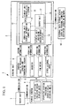
- Fig. 2 shows a flowchart of data acquisition by the above root-cause-of-fault-estimation-data acquiring section 13.
- the computing unit 14 determines whether or not the air conditioner 1 has just been powered on. If YES, the flow proceeds to step S2, where data (factor numbers ranked first to third) is read from the nonvolatile storage means (EEPROM) of the storage unit 15, and the flow proceeds to step S3. If NO, the flow skips step S2 and proceeds to step S3.
- EEPROM nonvolatile storage means
- step S3 it is determined whether or not the detection condition for any factor number described above has occurred. If YES, the flow proceeds to step S4; otherwise, if NO, the flow jumps to step S9, where the data (information) read from the EEPROM in step S2 is output to, for example, the display unit 16, and the flow ends.
- step S4 it is determined whether or not the occurrence of the factor number detection condition detected in step S3 is the first (earliest) after power-on. If YES, i.e., this is the first, the flow proceeds to step S5, where the data in the EEPROM is reset, and the flow proceeds to step S6. If NO, the flow skips step S5 and proceeds to step S6.
- step S6 the last ten factor numbers from the latest factor number detected in step S3 above are stored in the RAM.
- step S7 the three most-frequent factor numbers are computed. In this step, if fewer than three factor numbers have occurred, and therefore the relevant data is not available, a number corresponding to "not available" is computed.
- step S8 the first to third factor numbers newly computed are written in the nonvolatile storage means (EEPROM) of the storage unit 15, and in step S9, the factor numbers are output to, for example, the display unit 16.
- EEPROM nonvolatile storage means
- the root-cause-of-fault-estimation-data acquiring section 13 is configured to maintain the data stored in the nonvolatile storage means (EEPROM) until the first protection control factor or comp-stopping factor occurs after power-on of the air conditioner 1 and to output the data to the display unit 16 or via the external output unit 17 to the external data storage device 18 when necessary.
- the information stored in the root-cause-of-fault-estimation-data acquiring section 13 includes only the information about the last ten occurrences of protection control factors and comp-stopping factors from the latest occurrence.
- this embodiment provides the following advantageous effects.
- the air conditioner 1 if any protection control classified in the "protection control statuses" shown in Fig. 2 is activated without leading to error detection, or if any error detection classified in the "comp-stopping factors due to errors” shown in Fig. 3 is activated without leading to abnormal shutdown, the data for the last ten occurrences thereof is stored in the root-cause-of-fault-estimation-data acquiring section 13, and the first to third most-frequent factors are ranked and written in the storage unit 15, composed of nonvolatile storage means (EEPROM), and can be displayed on the display unit 16 or the external data storage device 18 when necessary.
- EEPROM nonvolatile storage means
- This information can be maintained in the storage unit 15 until the first protection control factor or error detection factor occurs after power-on of the air conditioner 1.
- the service personnel can output the above data stored in the air conditioner 1 to the display unit 16 or the external data storage device 18 and can analyze the data to estimate not only the direct cause that has led to abnormal shutdown, but also the root cause thereof.
- the above data can be analyzed for fault factor estimation, for example, as in sample 1, shown in Fig. 5 , or as in sample 2, shown in Fig. 6 .
- the first protection control factor is discharge pipe temperature protection, the second is low-pressure protection, and the third is compression ratio protection, whereas the first comp-stopping factor is discharge pipe temperature error, the second is low-pressure error, and the third is not available.
- the first protection control factor is discharge pipe temperature protection, the second is not available, and the third is not available, whereas the first comp-stopping factor is discharge pipe temperature error, the second is not available, and the third is not available.
- the root cause of the error for pattern 1 is estimated to be "insufficient refrigerant.”
- a faulty discharge pipe temperature sensor is unlikely because the fact that the compression ratio protection has been activated indicates that the condition for the discharge pipe temperature to rise has been satisfied in the refrigeration cycle; rather, in this case, it can be estimated that "insufficient refrigerant” is likely because both a discharge pipe temperature error and a low-pressure error have occurred, both of which occur due to "insufficient refrigerant.”
- the root cause of the error for pattern 2 is estimated to be a "faulty discharge pipe temperature sensor” or a "faulty Td cooling liquid bypass valve.” In this case, because only discharge pipe temperature protection and discharge pipe temperature error have occurred, the estimated factors are the factors that occur due to the discharge pipe temperature alone.
- the first protection control factor is power transistor (power trans) temperature protection
- the second is current safe protection
- the third is not available
- the first comp-stopping factor is power trans overheating error
- the second is current cut error
- the third is not available.
- the first protection control factor is current safe protection
- the second is not available
- the third is not available
- the first comp-stopping factor is current cut error
- the second is compressor startup failure
- the third is not available.
- the root cause of the error for pattern 1 is estimated to be a "faulty power trans.” Inverter protection due to an increased air-conditioning load is unlikely because no protection control has been activated in the refrigeration cycle; rather, in this case, it can be estimated that an "insufficient power trans” is likely because both a power trans overheating error and a current cut error have occurred, both of which occur due to an "insufficient power trans.”
- the root cause of the error for pattern 2 is estimated to be a "faulty compressor.” In this case, it can be estimated that a "faulty compressor” is likely because both a current cut error and a compressor startup failure have occurred, both of which occur due to a "faulty compressor.”
- the service personnel can display the information stored in the air conditioner 1 itself, specifically, the information about the ranking of at least three most-frequent protection control factors and error detection factors, on the display unit 16 and can analyze this information, not only to estimate the direct cause of an error, but also to estimate the root cause that has led to the error by grasping the information such as the types of factors and the activation tendencies of, for example, protection control activated without leading to error detection and error detection activated without leading to abnormal shutdown and utilizing this information as information for estimating the root cause of the fault.
- This allows the service personnel to employ a true solution to an error, rather than a stopgap measure, thus preventing reoccurrence of the error and enabling quick resolution of the error at the first visit after a service call.
- the root-cause-of-fault-estimation-data acquiring section 13 can compute at least three most-frequent protection control factors and error detection factors (comp-stopping factors due to errors) among a plurality of protection control factors and error detection factors, can write the factors in the storage unit 15, which is composed of nonvolatile storage means (EEPROM), and can read and display the factors on the display unit 16. This allows the information to be updated each time protection control or error detection is activated so that the information remains up to date, which assists in analyzing the root cause in the event of an error.
- EEPROM nonvolatile storage means
- the root-cause-of-fault-estimation-data acquiring section 13 includes the external output unit 17 for outputting information to the external data storage device 18.
- the external data storage device 18 such as a personal computer, a dedicated logger, or a network, can be connected to the external output unit 17 to retrieve information from the air conditioner 1 that has shut down abnormally, for analysis when necessary. This eliminates the need to analyze the cause of the occurrence of an error and the root cause thereof or to investigate, for example, the measures to be taken at the installation site of the air conditioner 1 that has shut down abnormally, thus enabling a suitable and quick service response at a convenient site.
- the storage unit 15 is configured to maintain the information stored therein until the first protection control factor or error detection factor occurs after power-on of the air conditioner 1.
- the previous information stored in the storage unit 15, which is composed of nonvolatile storage means (EEPROM) can be maintained until the first protection control factor or error detection factor occurs after power-on, which allows information about factors that have occurred before abnormal shutdown of the air conditioner 1 to be reliably retrieved from the storage unit 15.
- the computing unit 14 is configured to store only information about the last ten occurrences of protection control factors and error detection factors from the latest occurrence.
- the last ten occurrences of error factors from the latest occurrence can be stored. That is, only the latest information is stored because old information about extremely remote occurrences is likely to be irrelevant to the factors involved in abnormal shutdown. This allows more precise analysis based on the relevant latest information and requires a smaller memory space compared with storing information about all occurrences.
- the present invention is not limited to the invention according to the above embodiment; various modifications are possible without departing from the spirit thereof.
- the above embodiment illustrates a single-unit system including a single indoor unit 2 connected to a single outdoor unit 3, it should be understood that the invention is also applicable to a multiunit system including a plurality of indoor units 2 connected in parallel.
- the "protection control statuses,” “comp-stopping factors due to errors,” “sample 1,” “sample 2,” etc. above are merely illustrative and are not necessarily limited to those illustrated in the above embodiment.
Landscapes
- Engineering & Computer Science (AREA)
- Chemical & Material Sciences (AREA)
- Combustion & Propulsion (AREA)
- Mechanical Engineering (AREA)
- General Engineering & Computer Science (AREA)
- Health & Medical Sciences (AREA)
- Biomedical Technology (AREA)
- Air Conditioning Control Device (AREA)
Abstract
Description
- The present invention relates to air conditioners that allow acquisition of data for estimating the root cause of a fault that has led to abnormal shutdown of an air conditioner.
- Air conditioners have various protection functions and error detection functions. When they are activated, the contents thereof can be stored and displayed if necessary. This is so that, when an air conditioner is at fault, the service personnel can easily determine the cause of the fault to carry out proper repair. PTL (Patent Literature) 1 discloses an air conditioner having a protection function that is activated to protect the air conditioner in the event of an error and including a storage unit composed of rewritable nonvolatile memory (EEPROM) and a control unit that writes error data for the activated protection function in the storage unit and that reads the error data from the storage unit.
- In addition,
PTL 2 discloses a display method for air conditioners that detects an error in an air conditioner or determines the occurrence of a fault by error detection, that stores the error or fault in nonvolatile storage means (EEPROM), and that allows the stored error or fault to be displayed. This method allows the contents stored in the nonvolatile storage means to be displayed on a display unit when a control operation is performed on the air conditioner within a predetermined period of time from power-on of the air conditioner. -
- {PTL 1}
Japanese Unexamined Patent Application, Publication No.62-280534 - {PTL 2}
Japanese Unexamined Patent Application, Publication No.9-292152 - In general, the usage environment of an air conditioner varies greatly depending on the season and the user. A service call is made if a fault leads to abnormal shutdown of the air conditioner. The service personnel who responds to the call outputs error data from storage means as described above to determine the cause that has led to abnormal shutdown from the contents thereof, and carries out repair. In some cases, however, the service personnel cannot estimate the root cause of the error.
- In addition, even if the service personnel performs, for example, acquisition of detailed operation data after their arrival in order to estimate the root cause, it may be impossible to reproduce the error because the usage environment has changed since the occurrence of the error. As a result, the repair may end up in a stopgap measure that leaves the root cause unresolved. This causes a problem in that there remains the possibility of reoccurrence of the error, which may cause the user a considerable disadvantage.
- In light of the foregoing, an object of the present invention is to provide an air conditioner that can provide information from which the root cause of an error can be estimated in the event of a fault without depending on the ability of the service personnel.
- As used hereinbefore and hereinafter, the terms "protection control," "error detection," and "abnormal shutdown" are defined as follows:
- Protection control: Preventive control for avoiding an error state. For example, even though the rotational speed of the compressor is reduced, or bypass control is executed, the operation is continued.
- Error detection: The operation is temporarily stopped if a specific error detection condition is satisfied. The operation, however, is automatically resumed after a predetermined period of time (e.g., 3 minutes) elapses. No error display is shown on, for example, a remote control.
- Abnormal shutdown: The operation is permanently stopped if the frequency of error detection satisfies a specific abnormal shutdown condition. An error display is shown on, for example, a remote control, and the operation is not resumed unless the user removes the error state.
- To solve the above problem, an air conditioner of the present invention employs the following solutions.
Specifically, an air conditioner according to an aspect of the present invention includes a controller that controls operation of the air conditioner on the basis of information from sensors and operating information from devices and that executes protection control, error detection, and abnormal shutdown thereof. The controller includes a root-cause-of-fault-estimation-data acquiring section that computes at least first to third most-frequent protection control factors and error detection factors among a plurality of preset protection control factors and error detection factors, that ranks and stores the factors, and that allows the stored information to be displayed when necessary. - According to the aspect of the present invention, the controller that controls operation of the air conditioner and that executes protection control, error detection, and abnormal shutdown thereof includes a root-cause-of-fault-estimation-data acquiring section that computes at least first to third most-frequent protection control factors and error detection factors among a plurality of preset protection control factors and error detection factors, that ranks and stores the factors, and that allows the stored information to be displayed when necessary; therefore, if the air conditioner shuts down abnormally, the service personnel can display the information stored in the air conditioner itself, specifically, the information about at least the first to third most-frequent protection control factors and error detection factors, on, for example, a display unit and can analyze this information, not only to estimate the direct cause of an error, but also to estimate the root cause that has led to the error. That is, the service personnel can grasp the information such as the types of factors and the activation tendencies of, for example, protection control activated without leading to error detection and error detection activated without leading to abnormal shutdown and utilize this information as information for estimating the root cause of the fault. This allows the service personnel to employ a true solution to an error, rather than a stopgap measure, thus preventing reoccurrence of the error and enabling quick resolution of the error at the first visit after a service call.
- In any one of the air conditioners described above, additionally, the root-cause-of-fault-estimation-data acquiring section of the air conditioner of the above aspect includes a computing unit that computes at least first to third most-frequent protection control factors and error detection factors among the plurality of protection control factors and error detection factors, a storage unit composed of nonvolatile storage means for storing the information, and a display unit that reads and displays the information written in the storage unit when necessary.
- According to the above aspect, the root-cause-of-fault-estimation-data acquiring section includes a computing unit that computes at least first to third most-frequent protection control factors and error detection factors among the plurality of protection control factors and error detection factors, a storage unit composed of nonvolatile storage means for storing the information, and a display unit that reads and displays the information written in the storage unit when necessary; therefore, when necessary, via the computing unit, the root-cause-of-fault-estimation-data acquiring section can compute at least the first to third most-frequent protection control factors and error detection factors among the plurality of protection control factors and error detection factors, can rank and write the factors in the storage unit, which is composed of nonvolatile storage means (EEPROM), and can read and display the factors on the display unit. This allows the information to be updated each time protection control or error detection is activated so that the information remains up to date, which assists in analyzing the root cause in the event of an error.
- In any one of the air conditioners described above, additionally, the root-cause-of-fault-estimation-data acquiring section of the air conditioner of the above aspect includes an external output unit for outputting the information to an external data storage device.
- According to the above aspect, the root-cause-of-fault-estimation-data acquiring section includes an external output unit for outputting information to an external data storage device; therefore, an external data storage device, such as a personal computer, a dedicated logger, or a network, can be connected to the external output unit to retrieve the above information from the air conditioner that has shut down abnormally, for analysis when necessary. This eliminates the need to analyze the cause of the occurrence of an error and the root cause thereof or to investigate, for example, the measures to be taken at the installation site of the air conditioner that has shut down abnormally, thus enabling a suitable and quick service response at a convenient site.
- In any one of the air conditioners described above, additionally, the storage unit of the air conditioner of the above aspect is configured to maintain the information stored therein until a first protection control factor or error detection factor occurs after power-on of the air conditioner.
- According to the above aspect, the storage unit is configured to maintain the information stored therein until a first protection control factor or error detection factor occurs after power-on of the air conditioner; therefore, for example, even if the power is reset as a temporary measure in the event of an error, the previous information stored in the storage unit, which is composed of nonvolatile storage means (EEPROM), can be maintained until the first protection control factor or error detection factor occurs after power-on. This allows information about factors that have occurred before abnormal shutdown of the air conditioner to be reliably retrieved.
- In any one of the air conditioners described above, additionally, the computing unit of the air conditioner of the above aspect is configured to store only information about the last ten occurrences of the protection control factors and error detection factors from the latest occurrence.
- According to the above aspect, the computing unit is configured to store only information about the last ten occurrences of the protection control factors and error detection factors from the latest occurrence; thus, only the last ten occurrences of error factors from the latest occurrence can be stored. That is, only the latest information is stored because old information about extremely remote occurrences may be irrelevant to the factors involved in abnormal shutdown. This allows more precise analysis based on the relevant latest information and requires a smaller memory space compared with storing information about all occurrences.
- According to the present invention, if the air conditioner shuts down abnormally, the service personnel can display the information stored in the air conditioner itself, specifically, the information about at least the first to third most-frequent protection control factors and error detection factors, on, for example, a display unit and can analyze this information, not only to estimate the direct cause of an error, but also to estimate the root cause that has led to the error. That is, the service personnel can grasp the type of factor, the operating tendency, etc. and use them as useful information for estimating the root cause of a fault, for example, when protection control is activated without leading to error detection, or when error detection is activated without leading to abnormal shutdown, which allows the service personnel to employ a true solution to an error, rather than a stopgap measure, thus preventing reoccurrence of the error and enabling quick resolution of the error at the first visit after a service call.
-
- {
Fig. 1 }
Fig. 1 is a schematic block diagram of an air conditioner according to an embodiment of the present invention. - {
Fig. 2 }
Fig. 2 is a flowchart of data acquisition by a root-cause-of-fault-estimation-data acquiring section of the air conditioner shown inFig. 1 . - {
Fig. 3 }
Fig. 3 is an illustration of the contents and numbers of protection control statuses set in the root-cause-of-fault-estimation-data acquiring section of the air conditioner shown inFig. 1 . - {
Fig. 4 }
Fig. 4 is an illustration of the contents and numbers of compressor-stopping factors (comp-stopping factors) due to errors set in the root-cause-of-fault-estimation-data acquiring section of the air conditioner shown inFig. 1 . - {
Fig. 5 }
Fig. 5 is an illustration ofsample 1 showing how to estimate a factor involved in a fault from information acquired by the root-cause-of-fault-estimation-data acquiring section of the air conditioner shown inFig. 1 . - {
Fig. 6 }
Fig. 6 is an illustration ofsample 2 showing how to estimate a factor involved in a fault from information acquired by the root-cause-of-fault-estimation-data acquiring section of the air conditioner shown inFig. 1 . - An embodiment of the present invention will be described below with reference to
Figs. 1 to 6 .
Fig. 1 shows a schematic block diagram of an air conditioner according to an embodiment of the present invention, andFig. 2 shows a flowchart of control performed by a root-cause-of-fault-estimation-data acquiring section.
Anair conditioner 1 includes anoutdoor unit 2, at least oneindoor unit 3, and aremote control 4 connected to theindoor unit 3. Theoutdoor unit 2 and theindoor unit 3 are connected via a refrigerant pipe (not shown), and theoutdoor unit 2, theindoor unit 3, and theremote control 4 are connected viacommunication lines 5. - The
remote control 4 includes, for example, adisplay section 6 including an error display unit and anoperating section 7 including an error-display clearing unit. In addition, theoutdoor unit 2 includes, for example, anoutdoor controller 12 that controls the operation of theair conditioner 1 based on information fromsensors 8, such as a pressure sensor and a temperature sensor, and operating information from devices, such as aninverter 9, afan motor 10, and other external input means 11, and that executes protection control, error detection, and abnormal shutdown, the details of which will be described later. - The
air conditioner 1 also has many functions for protecting theair conditioner 1 and detecting errors based on information such as information from thesensors 8 and operating information from thedevices 9 to 11.Fig. 3 shows an example of a list of statuses of protection control executed in theair conditioner 1 and status numbers corresponding thereto. After theair conditioner 1 is powered on and started up, if any protection control among the protection controls classified in the predefined "protection control statuses" shown inFig. 3 is activated, the corresponding status number is stored in and displayed on theoutdoor controller 12. - For example, as a protection control, if "high-pressure (HP) protection control," which reduces the rotational speed of a compressor if the high pressure (HP) rises and the pressure detected by a high-pressure pressure sensor reaches a preset level or higher, is activated, the
status number 1 is stored. If a plurality of protection controls among the protection controls shown inFig. 3 occur simultaneously, the number of the protection control having the highest number is stored and displayed. - As an example of error detection control,
Fig. 4 shows an example of a list of compressor (comp)-stopping factors due to errors and factor numbers corresponding thereto. After theair conditioner 1 is powered on and started up, if the compressor is temporarily stopped due to any comp-stopping factor among the comp-stopping factors classified in the predefined "comp-stopping factors" shown inFig. 4 , the corresponding factor number is displayed on theoutdoor controller 12. - For example, as a comp-stopping factor, if the compressor is temporarily stopped due to an HP error (high-pressure error), the
factor number 20 is stored. This comp-stopping factor is stored as the most recent comp-stopping factor due to an error or a special control (excluding normal stopping) at the present time, and the number output is maintained until the next comp-stopping factor occurs. If a plurality of comp-stopping factors occur simultaneously, the factor number is updated to that of the last error state resolved and is displayed. - In this embodiment, additionally, the
outdoor controller 12 includes a root-cause-of-fault-estimation-data acquiring section 13 that acquires data for facilitating estimation and analysis of the root cause of a fault (error) that has led to abnormal shutdown of theair conditioner 1. The root-cause-of-fault-estimation-data acquiring section 13 includes acomputing unit 14 that computes, for example, output information, astorage unit 15 composed of nonvolatile storage means (EEPROM), adisplay unit 16 composed of, for example, a seven-segment display, and anexternal output unit 17 for outputting stored information via suitable communication means 19 to an externaldata storage device 18 such as a personal computer, a dedicated logger, or a network. - After the
air conditioner 1 is powered on and started up, if any protection control among the "protection control statuses" defined inFig. 3 is activated, or if the compressor is temporarily stopped due to any factor among the "comp-stopping factors" defined inFig. 4 , thecomputing unit 14 stores information about the last ten occurrences of protection control statuses and comp-stopping factors from the latest occurrence, computes at least three most-frequent protection control statuses and comp-stopping factors of the ten protection control statuses and comp-stopping factors, ranks and stores the factors in thestorage unit 15, and displays the factors on thedisplay unit 16. - In response to an instruction from the
computing unit 14, thestorage unit 15, composed of nonvolatile storage means (EEPROM), functions to write and store information about the ranking of at least the first to third most-frequent protection control statuses and comp-stopping factors in the EEPROM and to maintain the information until the first protection control factor or error detection factor occurs after power-on of theair conditioner 1, and can also read this information for display on, for example, thedisplay unit 16 when necessary. - In response to an instruction from the
computing unit 14, thedisplay unit 16 displays necessary information on the seven-segment display. Similarly, in response to an instruction from thecomputing unit 14, the external output unit outputs necessary information to the externaldata storage device 18 connected thereto so that the above information can be retrieved from theair conditioner 1. The above error occurrence information can also be displayed on thedisplay section 6 of theremote control 4. -
Fig. 2 shows a flowchart of data acquisition by the above root-cause-of-fault-estimation-data acquiring section 13.
When theair conditioner 1 is started up, in step S1, thecomputing unit 14 determines whether or not theair conditioner 1 has just been powered on. If YES, the flow proceeds to step S2, where data (factor numbers ranked first to third) is read from the nonvolatile storage means (EEPROM) of thestorage unit 15, and the flow proceeds to step S3. If NO, the flow skips step S2 and proceeds to step S3. - In step S3, it is determined whether or not the detection condition for any factor number described above has occurred. If YES, the flow proceeds to step S4; otherwise, if NO, the flow jumps to step S9, where the data (information) read from the EEPROM in step S2 is output to, for example, the
display unit 16, and the flow ends. In step S4, it is determined whether or not the occurrence of the factor number detection condition detected in step S3 is the first (earliest) after power-on. If YES, i.e., this is the first, the flow proceeds to step S5, where the data in the EEPROM is reset, and the flow proceeds to step S6. If NO, the flow skips step S5 and proceeds to step S6. - In step S6, the last ten factor numbers from the latest factor number detected in step S3 above are stored in the RAM. The flow then proceeds to step S7, where the three most-frequent factor numbers are computed. In this step, if fewer than three factor numbers have occurred, and therefore the relevant data is not available, a number corresponding to "not available" is computed. In step S8, the first to third factor numbers newly computed are written in the nonvolatile storage means (EEPROM) of the
storage unit 15, and in step S9, the factor numbers are output to, for example, thedisplay unit 16. - Thus, the root-cause-of-fault-estimation-
data acquiring section 13 is configured to maintain the data stored in the nonvolatile storage means (EEPROM) until the first protection control factor or comp-stopping factor occurs after power-on of theair conditioner 1 and to output the data to thedisplay unit 16 or via theexternal output unit 17 to the externaldata storage device 18 when necessary. In addition, the information stored in the root-cause-of-fault-estimation-data acquiring section 13 includes only the information about the last ten occurrences of protection control factors and comp-stopping factors from the latest occurrence. - With the above configuration, this embodiment provides the following advantageous effects.
During the operation of theair conditioner 1, if any protection control classified in the "protection control statuses" shown inFig. 2 is activated without leading to error detection, or if any error detection classified in the "comp-stopping factors due to errors" shown inFig. 3 is activated without leading to abnormal shutdown, the data for the last ten occurrences thereof is stored in the root-cause-of-fault-estimation-data acquiring section 13, and the first to third most-frequent factors are ranked and written in thestorage unit 15, composed of nonvolatile storage means (EEPROM), and can be displayed on thedisplay unit 16 or the externaldata storage device 18 when necessary. - This information can be maintained in the
storage unit 15 until the first protection control factor or error detection factor occurs after power-on of theair conditioner 1. Thus, if a service call is made after theair conditioner 1 shuts down abnormally, the service personnel, at the first visit, can output the above data stored in theair conditioner 1 to thedisplay unit 16 or the externaldata storage device 18 and can analyze the data to estimate not only the direct cause that has led to abnormal shutdown, but also the root cause thereof. - That is, the above data can be analyzed for fault factor estimation, for example, as in
sample 1, shown inFig. 5 , or as insample 2, shown inFig. 6 . - In
pattern 1, the first protection control factor is discharge pipe temperature protection, the second is low-pressure protection, and the third is compression ratio protection, whereas the first comp-stopping factor is discharge pipe temperature error, the second is low-pressure error, and the third is not available. Inpattern 2, the first protection control factor is discharge pipe temperature protection, the second is not available, and the third is not available, whereas the first comp-stopping factor is discharge pipe temperature error, the second is not available, and the third is not available. - In the case of
sample 1, generally, possible factors include: - (1) As possible causes of discharge pipe temperature error: a faulty discharge pipe temperature sensor, a faulty liquid bypass valve, a faulty control board, insufficient refrigerant, a short-circuit, etc.;
- (2) As possible causes of low-pressure error: a faulty low-pressure sensor, a closed control valve, a closed evaporator electronic expansion valve (activation failure), insufficient refrigerant, clogging (of the electronic expansion valve or strainer), etc.;
- (3) As possible causes of liquid-back error:
- piping/wiring mismatch, refrigerant overcharge, superheating control failure, a faulty liquid bypass circuit, a faulty supercooling coil circuit, a faulty compressor under-dome temperature sensor, etc.; and
- (4) As possible causes of high-pressure error:
- insufficient condenser heat exchanger capacity (short-circuit, blocked airflow, filter clogging, faulty fan motor, etc.),
- By analyzing the data acquired in
sample 1 based on the above possible factors, the root cause of the error forpattern 1 is estimated to be "insufficient refrigerant." A faulty discharge pipe temperature sensor is unlikely because the fact that the compression ratio protection has been activated indicates that the condition for the discharge pipe temperature to rise has been satisfied in the refrigeration cycle; rather, in this case, it can be estimated that "insufficient refrigerant" is likely because both a discharge pipe temperature error and a low-pressure error have occurred, both of which occur due to "insufficient refrigerant." The root cause of the error forpattern 2, on the other hand, is estimated to be a "faulty discharge pipe temperature sensor" or a "faulty Td cooling liquid bypass valve." In this case, because only discharge pipe temperature protection and discharge pipe temperature error have occurred, the estimated factors are the factors that occur due to the discharge pipe temperature alone. - In
pattern 1, the first protection control factor is power transistor (power trans) temperature protection, the second is current safe protection, and the third is not available, whereas the first comp-stopping factor is power trans overheating error, the second is current cut error, and the third is not available. Inpattern 2, the first protection control factor is current safe protection, the second is not available, and the third is not available, whereas the first comp-stopping factor is current cut error, the second is compressor startup failure, and the third is not available. - In the case of
sample 2, generally, possible factors include: - (1) As possible causes of power trans overheating: a faulty power trans, a faulty para trans sensor, a faulty inverter board power supply, inverter cooling fan error, etc.;
- (2) As possible causes of current cut: a faulty compressor, refrigerant leakage, a faulty power trans, a faulty inverter board power supply, etc.; and
- (3) As possible causes of compressor startup failure:
- power supply voltage failure, a faulty refrigerant circuit component, a faulty inverter board power supply, wiring or connector insertion failure, a faulty compressor, etc.
- By analyzing the data acquired in
sample 2 based on the above possible factors, the root cause of the error forpattern 1 is estimated to be a "faulty power trans." Inverter protection due to an increased air-conditioning load is unlikely because no protection control has been activated in the refrigeration cycle; rather, in this case, it can be estimated that an "insufficient power trans" is likely because both a power trans overheating error and a current cut error have occurred, both of which occur due to an "insufficient power trans." The root cause of the error forpattern 2, on the other hand, is estimated to be a "faulty compressor." In this case, it can be estimated that a "faulty compressor" is likely because both a current cut error and a compressor startup failure have occurred, both of which occur due to a "faulty compressor." - Thus, according to this embodiment, if the
air conditioner 1 shuts down abnormally, the service personnel can display the information stored in theair conditioner 1 itself, specifically, the information about the ranking of at least three most-frequent protection control factors and error detection factors, on thedisplay unit 16 and can analyze this information, not only to estimate the direct cause of an error, but also to estimate the root cause that has led to the error by grasping the information such as the types of factors and the activation tendencies of, for example, protection control activated without leading to error detection and error detection activated without leading to abnormal shutdown and utilizing this information as information for estimating the root cause of the fault. This allows the service personnel to employ a true solution to an error, rather than a stopgap measure, thus preventing reoccurrence of the error and enabling quick resolution of the error at the first visit after a service call. - In addition, when necessary, via the
computing unit 14, the root-cause-of-fault-estimation-data acquiring section 13 can compute at least three most-frequent protection control factors and error detection factors (comp-stopping factors due to errors) among a plurality of protection control factors and error detection factors, can write the factors in thestorage unit 15, which is composed of nonvolatile storage means (EEPROM), and can read and display the factors on thedisplay unit 16. This allows the information to be updated each time protection control or error detection is activated so that the information remains up to date, which assists in analyzing the root cause in the event of an error. - In addition, the root-cause-of-fault-estimation-
data acquiring section 13 includes theexternal output unit 17 for outputting information to the externaldata storage device 18. Thus, the externaldata storage device 18, such as a personal computer, a dedicated logger, or a network, can be connected to theexternal output unit 17 to retrieve information from theair conditioner 1 that has shut down abnormally, for analysis when necessary. This eliminates the need to analyze the cause of the occurrence of an error and the root cause thereof or to investigate, for example, the measures to be taken at the installation site of theair conditioner 1 that has shut down abnormally, thus enabling a suitable and quick service response at a convenient site. - In this embodiment, furthermore, the
storage unit 15 is configured to maintain the information stored therein until the first protection control factor or error detection factor occurs after power-on of theair conditioner 1. Thus, even if the power is reset as a temporary measure in the event of an error, the previous information stored in thestorage unit 15, which is composed of nonvolatile storage means (EEPROM), can be maintained until the first protection control factor or error detection factor occurs after power-on, which allows information about factors that have occurred before abnormal shutdown of theair conditioner 1 to be reliably retrieved from thestorage unit 15. - In addition, the
computing unit 14 is configured to store only information about the last ten occurrences of protection control factors and error detection factors from the latest occurrence. Thus, only the last ten occurrences of error factors from the latest occurrence can be stored. That is, only the latest information is stored because old information about extremely remote occurrences is likely to be irrelevant to the factors involved in abnormal shutdown. This allows more precise analysis based on the relevant latest information and requires a smaller memory space compared with storing information about all occurrences. - The present invention is not limited to the invention according to the above embodiment; various modifications are possible without departing from the spirit thereof. For example, although the above embodiment illustrates a single-unit system including a single
indoor unit 2 connected to a singleoutdoor unit 3, it should be understood that the invention is also applicable to a multiunit system including a plurality ofindoor units 2 connected in parallel.
It should also be understood that the "protection control statuses," "comp-stopping factors due to errors," "sample 1," "sample 2," etc. above are merely illustrative and are not necessarily limited to those illustrated in the above embodiment. -
- 1
- air conditioner
- 2
- sensors
- 9
- inverter
- 10
- fan motor
- 11
- other external input means
- 12
- outdoor controller
- 13
- root-cause-of-fault-estimation-data acquiring section
- 14
- computing unit
- 15
- storage unit
- 16
- display unit
- 17
- external output unit
- 18
- external data storage device
Claims (5)
- An air conditioner comprising a controller that controls operation of the air conditioner on a basis of information from sensors and operating information from devices and that executes protection control, error detection, and abnormal shutdown thereof,
the controller including a root-cause-of-fault-estimation-data acquiring section that computes at least first to third most-frequent protection control factors and error detection factors among a plurality of preset protection control factors and error detection factors, that ranks and stores the factors, and that allows the stored information to be displayed when necessary. - The air conditioner according to Claim 1, wherein the root-cause-of-fault-estimation-data acquiring section includes a computing unit that computes at least first to third most-frequent protection control factors and error detection factors among the plurality of protection control factors and error detection factors, a storage unit comprising nonvolatile storage means for storing the information, and a display unit that reads and displays the information written in the storage unit when necessary.
- The air conditioner according to Claim 1 or 2, wherein the root-cause-of-fault-estimation-data acquiring section includes an external output unit for outputting the information to an external data storage device.
- The air conditioner according to Claim 2 or 3, wherein the storage unit is configured to maintain the information stored therein until a first protection control factor or error detection factor occurs after power-on of the air conditioner.
- The air conditioner according to any one of Claims 2 to 4, wherein the computing unit is configured to store only information about the last ten occurrences of the protection control factors and error detection factors from the latest occurrence.
Applications Claiming Priority (2)
| Application Number | Priority Date | Filing Date | Title |
|---|---|---|---|
| JP2010273775A JP2012122668A (en) | 2010-12-08 | 2010-12-08 | Air conditioner |
| PCT/JP2011/071713 WO2012077398A1 (en) | 2010-12-08 | 2011-09-22 | Air conditioner |
Publications (2)
| Publication Number | Publication Date |
|---|---|
| EP2650619A1 true EP2650619A1 (en) | 2013-10-16 |
| EP2650619A4 EP2650619A4 (en) | 2018-04-11 |
Family
ID=46206902
Family Applications (1)
| Application Number | Title | Priority Date | Filing Date |
|---|---|---|---|
| EP11847396.6A Withdrawn EP2650619A4 (en) | 2010-12-08 | 2011-09-22 | Air conditioner |
Country Status (4)
| Country | Link |
|---|---|
| EP (1) | EP2650619A4 (en) |
| JP (1) | JP2012122668A (en) |
| CN (1) | CN103314260A (en) |
| WO (1) | WO2012077398A1 (en) |
Cited By (3)
| Publication number | Priority date | Publication date | Assignee | Title |
|---|---|---|---|---|
| EP3220271A4 (en) * | 2014-12-18 | 2018-01-03 | Mitsubishi Heavy Industries Thermal Systems, Ltd. | Data collection device, data collection system, control method, and program |
| EP3495756A1 (en) * | 2017-12-07 | 2019-06-12 | Carrier Corporation | Refrigeration system, failure diagnostic system thereof, failure diagnostic method, controller and storage medium |
| CN112128919A (en) * | 2020-09-22 | 2020-12-25 | 珠海格力电器股份有限公司 | Air conditioner health state evaluation method and device, air conditioner and storage medium |
Families Citing this family (10)
| Publication number | Priority date | Publication date | Assignee | Title |
|---|---|---|---|---|
| WO2014084145A1 (en) * | 2012-11-30 | 2014-06-05 | 三菱電機株式会社 | Facility equipment operation device, facility equipment operation system, facility equipment operation method, and program |
| JP2015064182A (en) * | 2013-09-26 | 2015-04-09 | ダイキン工業株式会社 | Air conditioner |
| CN104748300B (en) * | 2015-02-27 | 2018-04-27 | 青岛海尔空调器有限总公司 | A kind of air conditioner fault aids in quick diagnosis control method |
| JP6503246B2 (en) * | 2015-07-02 | 2019-04-17 | 東芝キヤリア株式会社 | Control device of heat source machine for air handling unit |
| CN105241010B (en) * | 2015-10-14 | 2018-05-18 | 珠海格力电器股份有限公司 | Fault maintenance guidance information display method and device |
| CN105783198B (en) * | 2016-04-26 | 2019-04-30 | 广东美的制冷设备有限公司 | Air conditioner and its fault display method |
| CN106288568B (en) * | 2016-07-22 | 2019-08-20 | 珠海格力电器股份有限公司 | High-voltage protection control method and device for central air-conditioning compressor |
| JP2018146159A (en) * | 2017-03-03 | 2018-09-20 | 日立ジョンソンコントロールズ空調株式会社 | Air conditioner |
| JP6847278B2 (en) * | 2018-02-13 | 2021-03-24 | 三菱電機株式会社 | Remote controller and air conditioning hot water supply system |
| CN113639418A (en) * | 2020-04-27 | 2021-11-12 | 南通华信中央空调有限公司 | Air conditioner debugging method, air conditioner debugging device and related equipment |
Family Cites Families (11)
| Publication number | Priority date | Publication date | Assignee | Title |
|---|---|---|---|---|
| US4381549A (en) * | 1980-10-14 | 1983-04-26 | Trane Cac, Inc. | Automatic fault diagnostic apparatus for a heat pump air conditioning system |
| JP2703414B2 (en) * | 1991-03-25 | 1998-01-26 | 株式会社東芝 | Mail handling equipment |
| JP2576314B2 (en) * | 1991-09-13 | 1997-01-29 | ダイキン工業株式会社 | Fault diagnosis device |
| JPH06127834A (en) * | 1992-10-16 | 1994-05-10 | Murata Mach Ltd | Failure diagnostic system for automatic winder |
| JPH07318205A (en) * | 1994-05-24 | 1995-12-08 | Matsushita Refrig Co Ltd | Memory device for air-conditioning machine |
| JPH09292152A (en) * | 1996-04-25 | 1997-11-11 | Fujitsu General Ltd | Air conditioner display method |
| JP3448432B2 (en) * | 1996-07-17 | 2003-09-22 | 株式会社エヌ・ティ・ティ ファシリティーズ | Control device for air conditioner |
| JP2001033355A (en) * | 1999-07-19 | 2001-02-09 | Meiwa Electric Co | Support device for facility irregularity factor identification |
| JP4196804B2 (en) * | 2003-10-17 | 2008-12-17 | 日立アプライアンス株式会社 | Inverter air conditioner |
| JP4274205B2 (en) * | 2006-07-10 | 2009-06-03 | ダイキン工業株式会社 | Control device |
| JP2009175793A (en) * | 2008-01-21 | 2009-08-06 | Nakamura Tome Precision Ind Co Ltd | Abnormality recovery support system and method for machine tool |
-
2010
- 2010-12-08 JP JP2010273775A patent/JP2012122668A/en active Pending
-
2011
- 2011-09-22 EP EP11847396.6A patent/EP2650619A4/en not_active Withdrawn
- 2011-09-22 WO PCT/JP2011/071713 patent/WO2012077398A1/en not_active Ceased
- 2011-09-22 CN CN201180037216XA patent/CN103314260A/en active Pending
Non-Patent Citations (1)
| Title |
|---|
| See references of WO2012077398A1 * |
Cited By (4)
| Publication number | Priority date | Publication date | Assignee | Title |
|---|---|---|---|---|
| EP3220271A4 (en) * | 2014-12-18 | 2018-01-03 | Mitsubishi Heavy Industries Thermal Systems, Ltd. | Data collection device, data collection system, control method, and program |
| EP3495756A1 (en) * | 2017-12-07 | 2019-06-12 | Carrier Corporation | Refrigeration system, failure diagnostic system thereof, failure diagnostic method, controller and storage medium |
| US10768220B2 (en) | 2017-12-07 | 2020-09-08 | Carrier Corporation | Refrigeration system, failure diagnostic system thereof, failure diagnostic method, controller and storage medium |
| CN112128919A (en) * | 2020-09-22 | 2020-12-25 | 珠海格力电器股份有限公司 | Air conditioner health state evaluation method and device, air conditioner and storage medium |
Also Published As
| Publication number | Publication date |
|---|---|
| EP2650619A4 (en) | 2018-04-11 |
| JP2012122668A (en) | 2012-06-28 |
| CN103314260A (en) | 2013-09-18 |
| WO2012077398A1 (en) | 2012-06-14 |
Similar Documents
| Publication | Publication Date | Title |
|---|---|---|
| WO2012077398A1 (en) | Air conditioner | |
| US7295896B2 (en) | Automated part procurement and service dispatch | |
| US11015828B2 (en) | Refrigeration system with utilization unit leak detection | |
| CN108050663B (en) | Compressor self-protection control method and device, air conditioner and storage medium | |
| US7343750B2 (en) | Diagnosing a loss of refrigerant charge in a refrigerant system | |
| JP5405161B2 (en) | Air conditioner and energy equipment | |
| US10330099B2 (en) | HVAC compressor prognostics | |
| CN108361915B (en) | Fault detection method and device, air conditioner and computer readable storage medium | |
| JP4518208B2 (en) | Remote management system and remote management method for air conditioner | |
| CN101048713A (en) | System and method for detecting decreased performance in a refrigeration system | |
| CN109357357B (en) | Method for diagnosing compressor exhaust temperature detection abnormality, multi-split air conditioner, and storage medium | |
| ES2918206T3 (en) | Fault diagnosis system | |
| EP4116644A1 (en) | Equipment management system | |
| JP7676101B2 (en) | Air conditioner control device, air conditioner equipped with the same, air conditioner control method, and air conditioner control program | |
| CN102679495A (en) | Compensation starting method of air conditioner | |
| JP5216842B2 (en) | Air conditioner | |
| CN111121227B (en) | A fault detection method, detection device and air conditioner in a protection mode of a low pressure pressure switch | |
| CN115264754B (en) | Method and device for detecting subcooling valve failure, electronic device, and storage medium | |
| CN106679066B (en) | Unit fault judgment method and device | |
| CN113091205B (en) | Air conditioner abnormity detection method and device | |
| EP4491973A1 (en) | Protection method and device for high-temperature prevention during heating and refrigerant shortage during heating, and air conditioning system | |
| WO2007046791A1 (en) | Remote diagnostics and prognostics for refrigerant systems | |
| CN109186154B (en) | Four-way valve gas leakage protection fault diagnosis method and device, storage medium and air conditioner | |
| CN112361528A (en) | Control method and control device of air conditioner, storage medium and processor | |
| WO2018179333A1 (en) | Machine using refrigerant compression heat pump, diagnostic device for refrigerant compression heat pump, and diagnotic method for refrigerant compression heat pump |
Legal Events
| Date | Code | Title | Description |
|---|---|---|---|
| PUAI | Public reference made under article 153(3) epc to a published international application that has entered the european phase |
Free format text: ORIGINAL CODE: 0009012 |
|
| 17P | Request for examination filed |
Effective date: 20130129 |
|
| AK | Designated contracting states |
Kind code of ref document: A1 Designated state(s): AL AT BE BG CH CY CZ DE DK EE ES FI FR GB GR HR HU IE IS IT LI LT LU LV MC MK MT NL NO PL PT RO RS SE SI SK SM TR |
|
| DAX | Request for extension of the european patent (deleted) | ||
| RAP1 | Party data changed (applicant data changed or rights of an application transferred) |
Owner name: MITSUBISHI HEAVY INDUSTRIES THERMAL SYSTEMS, LTD. |
|
| RA4 | Supplementary search report drawn up and despatched (corrected) |
Effective date: 20180309 |
|
| RIC1 | Information provided on ipc code assigned before grant |
Ipc: F25B 49/00 20060101ALI20180306BHEP Ipc: F24F 11/30 20180101AFI20180306BHEP |
|
| STAA | Information on the status of an ep patent application or granted ep patent |
Free format text: STATUS: THE APPLICATION IS DEEMED TO BE WITHDRAWN |
|
| 18D | Application deemed to be withdrawn |
Effective date: 20181009 |