EP2650567A1 - Drive device and construction machine provided with same - Google Patents
Drive device and construction machine provided with same Download PDFInfo
- Publication number
- EP2650567A1 EP2650567A1 EP11847587.0A EP11847587A EP2650567A1 EP 2650567 A1 EP2650567 A1 EP 2650567A1 EP 11847587 A EP11847587 A EP 11847587A EP 2650567 A1 EP2650567 A1 EP 2650567A1
- Authority
- EP
- European Patent Office
- Prior art keywords
- motor
- brake
- speed reducer
- partition wall
- chamber
- Prior art date
- Legal status (The legal status is an assumption and is not a legal conclusion. Google has not performed a legal analysis and makes no representation as to the accuracy of the status listed.)
- Granted
Links
- 238000010276 construction Methods 0.000 title claims abstract description 37
- 239000003638 chemical reducing agent Substances 0.000 claims abstract description 144
- 239000010687 lubricating oil Substances 0.000 claims abstract description 90
- 238000005192 partition Methods 0.000 claims description 130
- 230000007246 mechanism Effects 0.000 claims description 112
- 238000007789 sealing Methods 0.000 claims description 83
- 230000000149 penetrating effect Effects 0.000 claims description 6
- 239000003921 oil Substances 0.000 description 32
- 230000002093 peripheral effect Effects 0.000 description 15
- 238000003780 insertion Methods 0.000 description 11
- 230000037431 insertion Effects 0.000 description 11
- 238000000034 method Methods 0.000 description 6
- 230000035515 penetration Effects 0.000 description 5
- 238000000638 solvent extraction Methods 0.000 description 4
- 230000008595 infiltration Effects 0.000 description 3
- 238000001764 infiltration Methods 0.000 description 3
- 239000000969 carrier Substances 0.000 description 2
- 239000004519 grease Substances 0.000 description 2
- 238000005461 lubrication Methods 0.000 description 2
- 238000010248 power generation Methods 0.000 description 2
- 238000007796 conventional method Methods 0.000 description 1
- 230000000694 effects Effects 0.000 description 1
- 230000001050 lubricating effect Effects 0.000 description 1
- 230000000630 rising effect Effects 0.000 description 1
Images


Classifications
-
- F—MECHANICAL ENGINEERING; LIGHTING; HEATING; WEAPONS; BLASTING
- F16—ENGINEERING ELEMENTS AND UNITS; GENERAL MEASURES FOR PRODUCING AND MAINTAINING EFFECTIVE FUNCTIONING OF MACHINES OR INSTALLATIONS; THERMAL INSULATION IN GENERAL
- F16H—GEARING
- F16H57/00—General details of gearing
- F16H57/02—Gearboxes; Mounting gearing therein
- F16H57/027—Gearboxes; Mounting gearing therein characterised by means for venting gearboxes, e.g. air breathers
-
- E—FIXED CONSTRUCTIONS
- E02—HYDRAULIC ENGINEERING; FOUNDATIONS; SOIL SHIFTING
- E02F—DREDGING; SOIL-SHIFTING
- E02F9/00—Component parts of dredgers or soil-shifting machines, not restricted to one of the kinds covered by groups E02F3/00 - E02F7/00
- E02F9/08—Superstructures; Supports for superstructures
- E02F9/10—Supports for movable superstructures mounted on travelling or walking gears or on other superstructures
- E02F9/12—Slewing or traversing gears
- E02F9/121—Turntables, i.e. structure rotatable about 360°
- E02F9/123—Drives or control devices specially adapted therefor
-
- E—FIXED CONSTRUCTIONS
- E02—HYDRAULIC ENGINEERING; FOUNDATIONS; SOIL SHIFTING
- E02F—DREDGING; SOIL-SHIFTING
- E02F9/00—Component parts of dredgers or soil-shifting machines, not restricted to one of the kinds covered by groups E02F3/00 - E02F7/00
- E02F9/08—Superstructures; Supports for superstructures
- E02F9/10—Supports for movable superstructures mounted on travelling or walking gears or on other superstructures
- E02F9/12—Slewing or traversing gears
- E02F9/121—Turntables, i.e. structure rotatable about 360°
- E02F9/128—Braking systems
-
- F—MECHANICAL ENGINEERING; LIGHTING; HEATING; WEAPONS; BLASTING
- F16—ENGINEERING ELEMENTS AND UNITS; GENERAL MEASURES FOR PRODUCING AND MAINTAINING EFFECTIVE FUNCTIONING OF MACHINES OR INSTALLATIONS; THERMAL INSULATION IN GENERAL
- F16H—GEARING
- F16H57/00—General details of gearing
- F16H57/04—Features relating to lubrication or cooling or heating
-
- F—MECHANICAL ENGINEERING; LIGHTING; HEATING; WEAPONS; BLASTING
- F16—ENGINEERING ELEMENTS AND UNITS; GENERAL MEASURES FOR PRODUCING AND MAINTAINING EFFECTIVE FUNCTIONING OF MACHINES OR INSTALLATIONS; THERMAL INSULATION IN GENERAL
- F16H—GEARING
- F16H57/00—General details of gearing
- F16H57/04—Features relating to lubrication or cooling or heating
- F16H57/0434—Features relating to lubrication or cooling or heating relating to lubrication supply, e.g. pumps; Pressure control
- F16H57/0443—Features relating to lubrication or cooling or heating relating to lubrication supply, e.g. pumps; Pressure control for supply of lubricant during tilt or high acceleration, e.g. problems related to the tilt or extreme acceleration of the transmission casing and the supply of lubricant under these conditions
-
- F—MECHANICAL ENGINEERING; LIGHTING; HEATING; WEAPONS; BLASTING
- F16—ENGINEERING ELEMENTS AND UNITS; GENERAL MEASURES FOR PRODUCING AND MAINTAINING EFFECTIVE FUNCTIONING OF MACHINES OR INSTALLATIONS; THERMAL INSULATION IN GENERAL
- F16H—GEARING
- F16H57/00—General details of gearing
- F16H57/04—Features relating to lubrication or cooling or heating
- F16H57/048—Type of gearings to be lubricated, cooled or heated
- F16H57/0482—Gearings with gears having orbital motion
- F16H57/0486—Gearings with gears having orbital motion with fixed gear ratio
-
- Y—GENERAL TAGGING OF NEW TECHNOLOGICAL DEVELOPMENTS; GENERAL TAGGING OF CROSS-SECTIONAL TECHNOLOGIES SPANNING OVER SEVERAL SECTIONS OF THE IPC; TECHNICAL SUBJECTS COVERED BY FORMER USPC CROSS-REFERENCE ART COLLECTIONS [XRACs] AND DIGESTS
- Y10—TECHNICAL SUBJECTS COVERED BY FORMER USPC
- Y10T—TECHNICAL SUBJECTS COVERED BY FORMER US CLASSIFICATION
- Y10T74/00—Machine element or mechanism
- Y10T74/19—Gearing
- Y10T74/19991—Lubrication
Definitions
- the present invention relates to a drive apparatus for reducing speed of a rotation force of an electric motor serving as a drive source using a speed reducer, and transmitting the reduced rotation force to a driven portion such as an upper slewing body in a construction machine such as a shovel.
- a shovel includes a crawler type lower propelling body, an upper slewing body installed on the lower propelling body rotatably around a shaft vertical to the ground, and a work attachment attached to the upper slewing body.
- a hybrid shovel or an electric shovel includes a slewing drive apparatus for causing the upper slewing body to slew.
- the slewing drive apparatus includes an electric motor (also referred to simply as a motor hereafter) serving as a drive source, and a speed reducer that reduces speed of a rotation force of the motor and transmits the reduced rotation force to the upper slewing body serving as a driven portion.
- the motor includes a motor shaft, and the speed reducer includes a speed reducer output shaft connected to the motor shaft.
- the motor and the speed reducer are provided in a row in an axial direction of the slewing drive apparatus (to be referred to hereafter as a apparatus-axis direction) such that both center axes (the motor shaft and the speed reducer output shaft) are located along the same line. Further, the motor and the speed reducer are mounted to an upper frame in such a vertical arrangement that the motor is located at a top.
- the speed reducer includes a casing surrounding a speed reducer chamber, and a speed reduction mechanism that is provided in the speed reducer chamber and includes at least single-stage planetary gear mechanism, for example.
- the planetary gear mechanism includes a sun gear, a planetary gear, and a ring gear. An output of the speed reducer is transmitted to the upper slewing body via a pinion provided on the speed reducer output shaft and a slewing gear provided on a lower frame of the lower propelling body.
- Lubricating oil for lubricating the speed reduction mechanism is injected into the speed reducer chamber (the casing).
- a temperature of the lubricating oil increases, and as a result of this temperature increase, a volume of the lubricating oil expands. Accordingly, an oil level of the lubricating oil rises, and as a result of the rising oil level, the lubricating oil may overflow.
- an internal pressure of the speed reducer chamber increases, a structure for sealing the motor shaft that is introduced into the speed reducer chamber may be damaged.
- an air chamber provided in a connecting part between the motor and the speed reducer is maintained at a pressure corresponding to atmospheric pressure (this function will be referred to hereafter as an air breather function). More specifically, in this technique, a part (to be referred to hereafter as an air breather) that enables the air chamber to communicate with the outside is provided to maintain the interior of the air chamber at a pressure corresponding to atmospheric pressure.
- a nacelle slewing drive apparatus for a wind power generation facility described in Patent Document 3 includes a clutch and a brake provided between a motor and a speed reducer, and an air chamber and an air breather disposed on an outer periphery of the clutch and brake.
- the technique of providing a dedicated air chamber having an air breather function is basically achieved by adding the air chamber between the motor and the speed reducer, and therefore an overall length (overall height) dimension of the device increases. As a result, a large space is required to install the drive apparatus.
- the air chamber is connected to a buffer tank disposed on the outside of the speed reducer by a passage, and therefore an internal volume of the buffer tank is used as a part of the air chamber.
- the buffer tank is disposed on the outside of the speed reducer under the premise that since the oil level of the lubricating oil takes the funnel-shape during an operation, the lubricating oil will flow into the buffer tank. During an operation on sloping ground, therefore, the lubricating oil likewise flows into the buffer tank due to the tilt of the construction machine. When, in this condition, the oil temperature is increased by direct sunlight or the like, air in the buffer tank expands, and as a result, the lubricating oil may overflow.
- the air breather function is not realized sufficiently even with a configuration employing a buffer tank.
- the buffer tank is disposed on the outside of the speed reducer, a diameter dimension of the drive apparatus increases. As a result, a large space is required to install the drive apparatus in a construction machine.
- Patent Document 3 Although the technique described in Patent Document 3 can be put to practical use in a wind power generation facility having substantially no dimensional limitations, the technique cannot easily be applied to a construction machine having severe dimensional limitations, such as a shovel.
- An object of the present invention is to provide a drive apparatus which is compact in a height direction and a diametrical direction and with which a sufficient air breather function can be obtained, and a construction machine including the drive apparatus.
- the present invention provides a drive apparatus for a construction machine, including: an electric motor serving as a drive source and having a motor shaft and a motor housing; and a speed reducer that includes a speed reducer output shaft for transmitting a force to a driven portion, a speed reduction mechanism that reduces a rotation force of the motor shaft and transmits the reduced rotation force to the speed reducer output shaft, and a casing surrounding a speed reducer chamber in which the speed reduction mechanism is housed and lubricating oil is injected, and that is provided below the electric motor such that the motor shaft and the speed reducer output shaft are disposed on an identical line, wherein an interior of the motor housing communicates with the speed reducer chamber such that a flow of air between the speed reducer chamber and the interior of the motor housing is permitted while limiting inflow of the lubricating oil into the interior of the motor housing from the speed reducer chamber, and an air breather for opening the interior of the motor housing to the atmosphere is provided in the motor housing.
- the present invention also provides a construction machine including the drive apparatus described above, and a driven portion driven by the force transmitted via the speed reducer.
- a sufficient air breather function can be obtained while achieving compactness in a height direction and a diametrical direction.
- the present invention may also be applied to another drive apparatus in which a motor and a speed reducer are arranged in a row in a apparatus-axis direction (a vertical direction) such that a motor shaft of the motor and a speed reducer output shaft of the speed reducer are arranged along the same line, and lubricating oil is injected into a casing of the speed reducer.
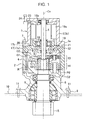
- a slewing drive apparatus shown in Fig. 1 includes an electric motor (to be referred to simply as a motor hereafter) 1 serving as a drive source, and a speed reducer 2 that reduces speed of a rotation force of the motor 1 and transmits the reduced rotation force to an upper slewing body serving as a driven portion.
- the motor 1 and the speed reducer 2 are arranged in a row in a apparatus-axis direction.
- the motor 1 includes a motor shaft 5, a rotation mechanism for applying a rotation force to the motor shaft 5, a motor housing 3 that houses the rotation mechanism, and a partition wall (a motor side partition wall) 17 provided below the motor housing 3.
- the rotation mechanism includes a rotor 16b attached to an outer periphery of the motor shaft 5, and a stator 16a fixed to an inner periphery of the motor housing 3.
- the motor housing 3 includes a tubular housing main body 3b that surrounds the rotation mechanism, and a flange 3a that projects to an outer periphery from a lower end portion of the housing main body 3b.
- the partition wall 17 partitions an interior of the motor housing 3 from a speed reducer chamber 12 to be described below. A specific configuration of the partition wall 17 will be described below.
- the speed reducer 2 includes at least single-stage planetary gear mechanism (two-stage planetary gear mechanisms are shown in Fig. 1 , and therefore a case in which two-stage planetary gear mechanisms are provided will be described below) 13, 14, a casing 4 surrounding the speed reducer chamber 12, in which the planetary gear mechanisms 13, 14 are housed and lubricating oil O is injected, a speed reducer output shaft 6 that is connected to the respective planetary gear mechanisms 13, 14 and projects from the casing 4, and a shaft support portion 8 that supports the speed reducer output shaft 6 rotatably.
- the motor 1 and the speed reducer 2 are arranged in a row in the apparatus-axis direction (a vertical direction) such that the motor shaft 5 and the speed reducer output shaft 6 are arranged along the same center line Ce. More specifically, the motor 1 and the speed reducer 2 are mounted to a construction machine in such a vertically arranged state that the motor 1 is located at a top and the motor 1 and the speed reducer 2 are provided in a row in the apparatus-axis direction.
- the flange 3a provided on the lower end of the motor housing 3 and the casing 4 are connected detachably by a plurality of connecting bolts 7.
- the shaft support portion 8 is provided on a lower end of the speed reducer 2 (below the casing 4), and has therein a bearing (not having a reference symbol) that rotatably supports the speed reducer output shaft 6.
- the shaft support portion 8 is provided with an attachment flange 9 that projects to an outer periphery from a lower portion thereof.
- the attachment flange 9 can be attached to an upper frame 10 of the upper slewing body by a plurality of attachment bolts 11.
- the casing 4 houses the two-stage planetary gear mechanisms 13, 14 arranged coaxially. Further, the lubricating oil O is injected into the casing 4 over the substantially whole length of the casing 4. More specifically, the lubricating oil O is injected over a range extending from a bottom surface of the casing 4 to a position slightly below an upper end surface of the casing 4 (a lower end surface of the partition wall 17 to be described below).
- an oil level of the lubricating oil O is horizontal, as shown by a reference symbol O1 in Figs. 1 and 2 .
- an outer peripheral side of the lubricating oil O is raised by a centrifugal force such that the oil level of the lubricating oil O takes the funnel-shape, as shown by a reference symbol 02 in Figs. 1 and 2 .
- the respective planetary gear mechanisms 13, 14 reduce speed of the rotation force of the motor shaft 5 and transmit the reduced rotation force to the speed reducer output shaft 6.
- the speed reducer output shaft 6 transmits the rotation force received from the motor shaft 5 to the upper frame 10 (the upper slewing body) serving as the driven portion.
- the planetary gear mechanisms 13, 14 respectively include sun gears S1, S2, carriers C1, C2, pluralities of planetary gears P1, P2 provided around the sun gears S1, S2 via the carriers C1, C2, and ring gears R provided on an inner periphery of the casing 4.
- the respective planetary gear mechanisms 13, 14 make the planetary gears P1, P2 revolve while making the planetary gears P1 and P2 rotate on their own axes, thereby reducing the speed of the rotation of motor 1.
- the reduced rotation force of the motor 1 is transmitted to the speed reducer output shaft 6, and then transmitted to the upper frame 10 via a pinion 15 provided on a lower end of the speed reducer output shaft 6 and a slewing gear (a ring gear, not shown) meshed to the pinion 15.
- the partition wall 17 partitions the interior of the motor housing 3 from the speed reducer chamber 12 when penetrated by the motor shaft 5. More specifically, the partition wall 17 is provided in a lower portion of the motor housing 3 (between the motor housing 3 and the casing 4). Further, the partition wall 17 includes a partition wall main body 17a formed in a ring shape, a grease lubrication bearing 18 provided on the partition wall main body 17a in order to support an intermediate portion of the motor shaft 5, and a shaft sealing mechanism (a motor side shaft sealing mechanism) 19 that seals a periphery of the motor shaft 5 below the bearing 18.
- a plurality of insertion holes 17b are formed in a vertical direction in a peripheral edge portion of the partition wall main body 17a.
- the partition wall main body 17a is attached to the motor housing 3 and the casing 4.
- a penetration hole 17c that can be penetrated by the motor shaft 5 is formed in a central portion of the partition wall main body 17a along the center line Ce.
- a connecting hole 20 that connects a space above the partition wall main body 17a to a space between the shaft sealing mechanism 19 and the bearing 18 in the penetration hole 17c is formed in the partition wall main body 17a.
- the shaft sealing mechanism 19 limits a flow of the lubricating oil O between the partition wall 17 (the partition wall main body 17a) and the motor shaft 5.
- the shaft sealing mechanism 19 is a non-contact type hermetic sealing mechanism in which a minute gap (a motor side air passage) 22 is formed between the shaft sealing mechanism 19 and the motor shaft 5 when the motor shaft 5 is inserted.
- a minute gap a motor side air passage 22 is formed between the shaft sealing mechanism 19 and the motor shaft 5 when the motor shaft 5 is inserted.
- the shaft sealing mechanism 19 includes a ring-shaped seal plate 21 that is fixed to the partition wall main body 17a.
- the seal plate 21 is attached to the partition wall main body 17a so as to block the penetration hole 17c such that flows of the lubricating oil O and air between the partition wall main body 17a and the seal plate 21 are limited.
- an insertion hole 21b into which the motor shaft 5 can be inserted is formed in the seal plate 21 along the center line Ce. As shown in Fig. 3 , an inner diameter dimension R2 of the insertion hole 21b is larger than an outer diameter dimension R1 of the motor shaft 5.
- the gap 22 is formed between an inside surface of the insertion hole 21 b and an outside surface of the motor shaft 5 at a width that corresponds to a difference (R2 - R1) between the respective radii R1, R2.
- the gap 22 forms an air passage (hereafter, the gap 22 will be referred to as an air passage) that allows air to flow between the speed reducer chamber 12 and the interior of the motor housing 3 while limiting inflow of the lubricating oil O between the speed reducer chamber 12 and the interior of the motor housing 3.
- the shaft sealing mechanism 19 constitutes an "oil groove sealing structure".
- oil groove sealing mechanism having oil grooves may also be employed on an outer peripheral surface of the motor shaft 5.
- a "gap sealing structure" not having oil grooves may also be employed.
- a "radial labyrinth sealing structure” in which a labyrinth passage is formed in a radial direction between the motor shaft 5 and the seal plate 21 may be employed.
- an “aligning labyrinth sealing structure” in which the labyrinth passage is formed so as to be inclined may be employed.
- the partition wall main body 17a and the seal plate 21 constitute a bottom wall of an interior chamber of the motor housing 3.
- the interior of the motor housing 3 and the speed reducer chamber 12 are connected to each other via the air passage 22 and the connecting hole 20.
- a part of an upper surface of the bottom wall of the interior chamber of the motor housing 3 constituted by the partition wall main body 17a and the seal plate 21 is recessed relative to other parts to form a recessed portion (a motor side recessed portion) 19a.
- the recessed portion 19a is formed in the partition wall 17.
- the seal plate 21 is attached to a lower surface of the partition wall such that a step is formed between the seal plate 21 and the partition wall main body 17a.
- the motor shaft 5 is inserted into the seal plate 21 in a region constituting a bottom portion of the recessed portion 19a.
- the air passage 22 is formed in the region constituting the bottom portion of the recessed portion 19a.
- a tunnel-shaped air breather passage 23 for leading air in the interior of the motor housing 3 to the outside is formed horizontally in the housing main body 3b of the motor housing 3.
- the air breather passage 23 communicates with the outside of the motor housing 3 via an air breather pipe 24.
- the air breather pipe 24 is formed in the shape of a chimney that extends upward from an outside surface of the housing main body 3b.
- the speed reducer chamber 12 is open to the atmosphere via the air passage 22, the connecting hole 20, the air breather passage 23, and the air breather pipe 24.
- the air passage 22, the connecting hole 20, the air breather passage 23, and the air breather pipe 24 together constitute an air breather that realizes an air breather function by connecting the speed reducer chamber 12 to the atmosphere via the interior space of the motor housing 3.
- the interior chamber of the motor housing 3 is used as an air chamber.
- a flow of air through the drive apparatus will be described.
- Dotted line arrows in Figs. 2 and 3 represent a flow of air that passes through the interior of the motor housing 3 from the speed reducer chamber 12 and then escapes to the outside. More specifically, the air in the speed reducer chamber 12 is introduced into the interior of the motor housing 3 through the air passage 22 and the connecting hole 20, as shown in Figs. 2 and 3 , as the temperature of the lubricating oil O increases and so on. The air in the interior of the motor housing 3 passes successively through the air breather passage 23 and the air breather pipe 24, and is thus led to the outside of the motor housing 3. Air on the outside of the motor housing 3, meanwhile, is introduced into the speed reducer chamber 12 along an opposite path to that described above.
- the inventors of the present application arrived at the invention described above, in which the interior of the motor housing 3 of the motor 1 doubles as the air chamber of the air breather, by focusing on the fact that a dry space including no oil is formed in the interior of the motor housing 3.
- a dry space including no oil is formed in the interior of the motor housing 3.
- a torque per unit size of the electric motor 1 is smaller than that of a hydraulic motor. Therefore, the electric motor 1, which is used to obtain an equivalent torque to that of a hydraulic motor, is larger than a hydraulic motor. Accordingly, the motor housing 3 originally has a large enough volume to realize the air breather function. Hence, there is no need to increase the size of the drive apparatus in the height direction and the diametrical direction when causing the interior of the motor housing 3 to double as an air chamber.
- the drive apparatus can be installed easily even in a construction machine having severe space limitations, such as a shovel.
- the shaft sealing mechanism 19 is provided in the part of the partition wall 17 partitioning the interior of the motor housing 3 from the speed reducer chamber 12 that is penetrated by the motor shaft 5. Therefore, infiltration of the lubricating oil O into the interior of the motor housing 3 during an operation can be suppressed. More specifically, during an operation, the oil level of the lubricating oil takes the funnel-shape, and therefore the likelihood of the lubricating oil O contacting (infiltrating) the part of the partition wall 17 penetrated by the motor shaft 5 is low.
- the air passage 22 is provided in the part of the partition wall 17 penetrated by the motor shaft 5.
- the air passage 22 is provided in the part penetrated by the motor shaft 5, where the oil level of the lubricating oil O during an operation is at a minimum and the lubricating oil O is unlikely to infiltrate even in a tilted condition.
- the lubricating oil O is less likely to contact the air passage 22 than when the air passage is formed on the outer peripheral side, and therefore the lubricating oil O is unlikely to infiltrate the interior of the motor housing 3 through the air passage 22.
- the air breather function can be secured at all times, even during an operation on sloping ground, and overflow of the lubricating oil can be prevented reliably.
- the recessed portion 19a is formed in the partition wall 17 by recessing a part of the upper surface of the partition wall 17 relative to the other parts thereof, and the air passage 22 is formed in the region constituting the bottom portion of the recessed portion 19a.
- a drive apparatus is a slewing drive apparatus having a brake. More specifically, the slewing drive apparatus having a brake includes a dry brake 25 that is provided between the motor 1 and the speed reducer 2 and applies a braking force to the motor shaft 5.
- the brake 25 includes a brake mechanism for applying a brake to the motor shaft 5, and a brake housing 26 surrounding a brake chamber 27 that houses the brake mechanism.
- the brake mechanism is a negative brake having a brake disc 28 that is splined to the motor shaft 5 and a brake pad 30 that generates a braking force when pressed against the brake disc 28 by a spring 29. More specifically, when oil pressure is supplied to the brake mechanism from an external oil pressure source, the brake pad 30 separates from the brake disc 28. As a result, the brake disc 28 is released from the braking force.
- the brake housing 26 surrounds the brake chamber 27 in which the brake mechanism is housed. More specifically, the brake housing 26 includes a peripheral wall 26a surrounding the brake mechanism about the center line Ce, and a partition wall (a brake side partition wall) 31 projecting inwardly from the peripheral wall 26a. An insertion hole 26b into which the connecting bolt 7 can be inserted is formed within a thickness range of the peripheral wall 26a. The connecting bolt 7 is inserted by screwing in a condition where the peripheral wall 26a is sandwiched between the partition wall 17 of the motor housing 3 and the casing 4 of the speed reducer 2. As a result, the brake 25 is fixed between the speed reducer 2 and the motor 1.
- the partition wall 31 partitions the speed reducer chamber 12 from the brake chamber 27 when penetrated by the motor shaft 5. More specifically, the partition wall 31 includes a partition wall main body 31a formed in a ring shape, and a shaft sealing mechanism (a brake side shaft sealing mechanism) 32 provided in a central portion of the partition wall main body 31 a. A penetration hole 31c that can be penetrated by the motor shaft 5 is formed in the central portion of the partition wall main body 31a along the center line Ce.
- the former will be referred to hereafter as the upper portion partition wall 17 and the upper portion shaft sealing mechanism 19, while the latter will be referred to as the lower portion partition wall 31 and the lower portion shaft sealing mechanism 32.
- the lower portion shaft sealing mechanism 32 limits a flow of the lubricating oil O between the lower portion partition wall 31 (the partition wall main body 31 a) and the motor shaft 5.
- the lower portion shaft sealing mechanism 32 is a non-contact type hermetic sealing mechanism in which a minute gap 34 is formed between the upper portion shaft sealing mechanism 32 and the motor shaft 5 when the motor shaft 5 is inserted. A specific configuration of the lower portion shaft sealing mechanism 32 will be described below.
- the lower portion shaft sealing mechanism 32 includes a ring-shaped seal plate 33 that is fixed to the partition wall main body 31 a.
- the seal plate 33 is attached to the partition wall main body 31a so as to block the penetration hole 31 c such that flows of the lubricating oil O and air between the partition wall main body 31a and the seal plate 33 are limited.
- an insertion hole 33b into which the motor shaft 5 can be inserted is formed in the seal plate 33 along the center line Ce.
- an inner diameter dimension of the insertion hole 33b is larger than the outer diameter dimension R1 (see Fig. 3 ) of the motor shaft 5.
- the gap 34 is formed between an inside surface of the insertion hole 33b and the outside surface of the motor shaft 5 at a width that corresponds to a difference between the respective radii.
- the gap 34 forms a brake side air passage (hereafter, the gap 34 will be referred to as an air passage) that allows air to flow between the speed reducer chamber 12 and the brake chamber 27 while limiting inflow of the lubricating oil O into the brake chamber 27 from the speed reducer chamber 12.
- the lower portion shaft sealing mechanism 32 constitutes an "oil groove sealing structure".
- an oil groove sealing mechanism having oil grooves may also be employed on the outer peripheral surface of the motor shaft 5.
- the "gap sealing structure”, the “radial labyrinth sealing structure” or the “aligning labyrinth sealing structure” described above may also be employed.
- the lower portion partition wall main body 31a and the seal plate 33 together constitute a bottom wall of the brake chamber 27.
- the speed reducer chamber 12 and the brake chamber 27 are connected by the air passage 34 alone.
- a part of an upper surface of the bottom wall of the brake chamber 27 constituted by the lower portion partition wall main body 31a and the seal plate 33 is recessed relative to the other parts to form a recessed portion (a brake side recessed portion) 32a.
- the recessed portion 32a is formed in the partition wall 31.
- the seal plate 33 is attached to a lower surface of the partition wall such that a step is formed between the seal plate 33 and the partition wall main body 31a.
- At least one air vent 35 is provided in the brake disc 28 to connect an upper portion space and a lower portion space of the brake disc 28 to each other.
- Dotted line arrows in Fig. 5 represent a flow of air that is passed through the brake chamber 27 and the interior of the motor housing 3 from the speed reducer chamber 12 by the air breather and then escapes to the outside. More specifically, the air in the speed reducer chamber 12 is introduced into the brake chamber 27 through the air passage 34 as the temperature of the lubricating oil O increases and so on. The air in the brake chamber 27 is introduced into the interior of the motor housing 3 via the air vent 35, the air passage 22, and the connecting hole 20. The air in the interior of the motor housing 3 is led to the outside of the motor housing 3 through the air breather passage 23 and the air breather pipe 24. Air on the outside of the motor housing 3, meanwhile, is introduced into the speed reducer chamber 12 along an opposite path to that described above.
- the lower portion partition wall 31 is provided to partition the brake chamber 27 from the speed reducer chamber 12. Therefore, in the drive apparatus having a brake, in which the dry brake 25 is provided between the motor 1 and the speed reducer 2, the brake chamber 27 of the brake 25 adjacent to the motor 1 can be caused to double as an air chamber. As a result, a volume of the air chamber is increased to a combined volume of the brake chamber 27 and the interior of the motor housing 3, and therefore the air breather function can be realized more efficiently.
- the two partition walls 17, 31 are provided between the interior of the motor housing 3 and the speed reducer chamber 12, and therefore, even if the lubricating oil O infiltrates the brake chamber 27 from the speed reducer chamber 12, the lubricating oil is unlikely to advance into the motor housing 3. As a result, the air breather function can be secured even during an operation on sloping ground.
- the brake chamber 27 exists between the interior of the motor housing 3 and the speed reducer chamber 12.
- the upper portion partition wall 17 is provided between the interior of the motor housing 3 and the brake chamber 27, while the lower portion partition wall 31 is provided between the brake chamber 27 and the speed reducer chamber 12. Hence, inflow of the lubricating oil O can be limited while permitting a flow of air using the shaft sealing mechanisms 19, 32 provided on the respective partition walls 17, 31.
- the recessed portion 32a is formed in the lower portion partition wall 31 by recessing a part of the upper surface of the lower portion partition wall 31 relative to the other parts thereof, and the air passage 34 is formed in the region constituting the bottom portion of the recessed portion 32a.
- the recessed portion 19a is likewise formed in the upper portion partition wall 17. Therefore, even if the lubricating oil O infiltrates the interior of the motor housing 3, the lubricating oil O is highly likely to be led to the bottom portion of the recessed portion 19a and then discharged downward (to the brake chamber 27 and then into the speed reducer chamber 12) through the air passage 22 in the upper portion shaft sealing mechanism 19.
- the present invention provides a drive apparatus for a construction machine, including: an electric motor serving as a drive source and having a motor shaft and a motor housing; and a speed reducer that includes a speed reducer output shaft for transmitting a force to a driven portion, a speed reduction mechanism that reduces a rotation force of the motor shaft and transmits the reduced rotation force to the speed reducer output shaft, and a casing surrounding a speed reducer chamber in which the speed reduction mechanism is housed and lubricating oil is injected, and that is provided below the electric motor such that the motor shaft and the speed reducer output shaft are arranged along a same line, wherein an interior of the motor housing communicates with the speed reducer chamber such that a flow of air between the speed reducer chamber and the interior of the motor housing is permitted while limiting inflow of the lubricating oil into the interior of the motor housing from the speed reducer chamber, and an air breather for opening the interior of the motor housing to the atmosphere is provided in the motor housing.
- the inventors of the present application arrived at the invention described above, in which the interior of the motor housing of the electric motor doubles as the air chamber of the air breather, by focusing on the fact that a dry space including no oil is formed in the interior of the motor housing. By causing the interior of the motor housing to double as an air chamber, there is no need to add a dedicated air chamber to the air breather.
- an electric motor capable of outputting equivalent torque to that of a hydraulic motor is larger than a hydraulic motor. Accordingly, the motor housing originally has a large enough volume to realize the air breather function. Hence, there is no need to increase the size of the drive apparatus in the height direction and the diametrical direction when causing the interior of the motor housing to double as an air chamber.
- the drive apparatus can be installed easily even in a construction machine having severe space limitations, such as a shovel.
- the electric motor preferably includes a motor side partition wall that partitions the interior of the motor housing from the speed reducer chamber, the motor shaft penetrating the motor side partition wall, and the motor side partition wall is preferably provided with a motor side shaft sealing mechanism that limits a flow of the lubricating oil between the motor side partition wall and the motor shaft, and a motor side air passage that permits a flow of air between the speed reducer chamber and the interior of the motor housing while limiting inflow of the lubricating oil into the interior of the motor housing from the speed reducer chamber.
- the motor side partition wall is provided to partition the interior of the motor housing from the speed reducer chamber. Therefore, in a drive apparatus in which the motor and the speed reducer are provided adjacent to each other, or in other words a drive apparatus in which the speed reducer chamber is close to the interior of the motor housing, inflow of the lubricating oil into the interior of the motor housing from the speed reducer chamber can be limited reliably by the partition wall and the shaft sealing mechanism provided thereon.
- the air breather function can be secured even during an operation on sloping ground, and overflow of the lubricating oil can be prevented reliably.
- the motor side shaft sealing mechanism is preferably a non-contact type hermetic sealing mechanism in which a minute gap serving as the motor side air passage is formed between the motor side shaft sealing mechanism and the motor shaft when the motor shaft is inserted.
- the motor side air passage is provided in the part into which the motor shaft is inserted, where the oil level of the lubricating oil during an operation is at a minimum and the lubricating oil is unlikely to infiltrate even in a tilted condition. Therefore, inflow of the lubricating oil into the interior of the motor housing from the speed reducer chamber can be limited more reliably even during an operation performed on sloping ground, and a flow of air through the motor side air passage can be secured more reliably. As a result, an even more reliable air breather function can be obtained.
- a motor side recessed portion is preferably formed in the motor side partition wall by recessing a part of an upper surface of the motor side partition wall relative to another part thereof, and the motor side air passage is preferably formed in a region constituting a bottom portion of the motor side recessed portion.
- the motor side air passage is formed in the region constituting the bottom portion of the motor side recessed portion.
- the drive apparatus for a construction machine described above preferably further includes a dry brake provided between the electric motor and the speed reducer, the brake including a brake mechanism for applying a brake to the motor shaft and a brake housing surrounding a brake chamber in which the brake mechanism is housed, wherein the brake housing includes a brake side partition wall that partitions the brake chamber from the speed reducer chamber, the motor shaft penetrating the brake side partition wall, the brake side partition wall is provided with a brake side shaft sealing mechanism that limits a flow of the lubricating oil between the brake side partition wall and the motor shaft and a brake side air passage that permits a flow of air between the speed reducer chamber and the brake chamber while limiting inflow of the lubricating oil into the brake chamber from the speed reducer chamber, and air is permitted to flow between the brake chamber and the interior of the motor housing.
- the brake housing includes a brake side partition wall that partitions the brake chamber from the speed reducer chamber, the motor shaft penetrating the brake side partition wall, the brake side partition wall is provided with a brake side
- the brake side partition wall is provided to partition the brake chamber from the speed reducer chamber. Therefore, in the drive apparatus having a brake, in which the dry brake is provided between the motor and the speed reducer, the brake chamber of the brake adjacent to the motor can be caused to double as an air chamber. As a result, the volume of the air chamber is increased to the combined volume of the brake chamber and the interior of the motor housing, and therefore the air breather function can be realized more efficiently.
- the air breather function can be secured even during an operation on sloping ground, and overflow of the lubricating oil can be prevented reliably.
- the brake side shaft sealing mechanism is preferably a non-contact type hermetic sealing mechanism in which a minute gap serving as the brake side air passage is formed between the brake side shaft sealing mechanism and the motor shaft when the motor shaft is inserted.
- the brake side air passage is provided in the part into which the motor shaft is inserted, where the oil level of the lubricating oil during an operation is at a minimum and the lubricating oil is unlikely to infiltrate even in a tilted condition. Therefore, inflow of the lubricating oil into the brake chamber and the interior of the motor housing from the speed reducer chamber can be limited more reliably even during an operation performed on sloping ground, and a flow of air through the brake side air passage can be secured more reliably. As a result, an even more reliable air breather function can be obtained.
- a brake side recessed portion is preferably formed in the brake side partition wall by recessing a part of an upper surface of the brake side partition wall relative to another part thereof, and the brake side air passage is preferably formed in a region constituting a bottom portion of the brake side recessed portion.
- the brake side air passage is formed in the region constituting the bottom portion of the brake side recessed portion.
- the electric motor preferably includes a motor side partition wall that partitions the interior of the motor housing from the brake chamber, the motor shaft penetrating the motor side partition wall, and the motor side partition wall is preferably provided with a motor side shaft sealing mechanism that limits a flow of the lubricating oil between the motor side partition wall and the motor shaft, and a motor side air passage that permits a flow of air between the brake chamber and the interior of the motor housing while limiting inflow of the lubricating oil into the interior of the motor housing from the brake chamber.
- the motor side partition wall provided with the motor side shaft sealing mechanism and the motor side air passage is further provided in addition to the brake side partition wall. Therefore, infiltration of the lubricating oil into the interior of the motor housing can be suppressed even more reliably by a double sealing effect between the speed reducer chamber and the brake chamber and between the brake chamber and the interior of the motor housing.
- the motor side shaft sealing mechanism is preferably a non-contact type hermetic sealing mechanism in which a minute gap serving as the motor side air passage is formed between the motor side shaft sealing mechanism and the motor shaft when the motor shaft is inserted.
- the motor side air passage is provided in the part into which the motor shaft is inserted, where the oil level of the lubricating oil during an operation is at a minimum and the lubricating oil is unlikely to infiltrate even in a tilted condition. Therefore, inflow of the lubricating oil into the interior of the motor housing from the speed reducer chamber can be limited more reliably even during an operation performed on sloping ground, and a flow of air through the motor side air passage can be secured more reliably. As a result, an even more reliable air breather function can be obtained.
- a motor side recessed portion is preferably formed in the motor side partition wall by recessing a part of an upper surface of the motor side partition wall relative to another part thereof, and the motor side air passage is preferably formed in a region constituting a bottom portion of the motor side recessed portion.
- the motor side air passage is formed in the region constituting the bottom portion of the motor side recessed portion.
- the electric motor preferably includes a rotation mechanism for applying a rotation force to the motor shaft, and the motor housing preferably houses the rotation mechanism.
- the present invention provides a construction machine including the drive apparatus described above, and a driven portion driven by the force transmitted via the speed reducer.
- a sufficient air breather function can be obtained while achieving compactness in a height direction and a diametrical direction.
Landscapes
- Engineering & Computer Science (AREA)
- General Engineering & Computer Science (AREA)
- Mechanical Engineering (AREA)
- Mining & Mineral Resources (AREA)
- Civil Engineering (AREA)
- Structural Engineering (AREA)
- General Details Of Gearings (AREA)
Abstract
Description
- The present invention relates to a drive apparatus for reducing speed of a rotation force of an electric motor serving as a drive source using a speed reducer, and transmitting the reduced rotation force to a driven portion such as an upper slewing body in a construction machine such as a shovel.
- The related art will now be described, using a slewing drive apparatus for a shovel as an example.
- A shovel includes a crawler type lower propelling body, an upper slewing body installed on the lower propelling body rotatably around a shaft vertical to the ground, and a work attachment attached to the upper slewing body.
- Here, a hybrid shovel or an electric shovel includes a slewing drive apparatus for causing the upper slewing body to slew. The slewing drive apparatus includes an electric motor (also referred to simply as a motor hereafter) serving as a drive source, and a speed reducer that reduces speed of a rotation force of the motor and transmits the reduced rotation force to the upper slewing body serving as a driven portion.
- The motor includes a motor shaft, and the speed reducer includes a speed reducer output shaft connected to the motor shaft. The motor and the speed reducer are provided in a row in an axial direction of the slewing drive apparatus (to be referred to hereafter as a apparatus-axis direction) such that both center axes (the motor shaft and the speed reducer output shaft) are located along the same line. Further, the motor and the speed reducer are mounted to an upper frame in such a vertical arrangement that the motor is located at a top.
- The speed reducer includes a casing surrounding a speed reducer chamber, and a speed reduction mechanism that is provided in the speed reducer chamber and includes at least single-stage planetary gear mechanism, for example. The planetary gear mechanism includes a sun gear, a planetary gear, and a ring gear. An output of the speed reducer is transmitted to the upper slewing body via a pinion provided on the speed reducer output shaft and a slewing gear provided on a lower frame of the lower propelling body.
- Lubricating oil for lubricating the speed reduction mechanism is injected into the speed reducer chamber (the casing). When the drive apparatus is operative, a temperature of the lubricating oil increases, and as a result of this temperature increase, a volume of the lubricating oil expands. Accordingly, an oil level of the lubricating oil rises, and as a result of the rising oil level, the lubricating oil may overflow. Further, when an internal pressure of the speed reducer chamber increases, a structure for sealing the motor shaft that is introduced into the speed reducer chamber may be damaged.
- Hence, in a conventional technique (see
Patent Documents - Meanwhile, a nacelle slewing drive apparatus for a wind power generation facility described in
Patent Document 3 includes a clutch and a brake provided between a motor and a speed reducer, and an air chamber and an air breather disposed on an outer periphery of the clutch and brake. - The technique of providing a dedicated air chamber having an air breather function, as described in
Patent Documents - It is therefore particularly difficult to dispose the drive apparatus described in
Patent Documents - Since the height dimension of the air chamber in an actual device is limited, it is impossible to secure sufficient volume in the air chamber. As a result, the air breather function may not be realized sufficiently.
- In the technique described in
Patent Document 1, the air chamber is connected to a buffer tank disposed on the outside of the speed reducer by a passage, and therefore an internal volume of the buffer tank is used as a part of the air chamber. - However, the buffer tank is disposed on the outside of the speed reducer under the premise that since the oil level of the lubricating oil takes the funnel-shape during an operation, the lubricating oil will flow into the buffer tank. During an operation on sloping ground, therefore, the lubricating oil likewise flows into the buffer tank due to the tilt of the construction machine. When, in this condition, the oil temperature is increased by direct sunlight or the like, air in the buffer tank expands, and as a result, the lubricating oil may overflow.
- In other words, the air breather function is not realized sufficiently even with a configuration employing a buffer tank.
- Furthermore, since the buffer tank is disposed on the outside of the speed reducer, a diameter dimension of the drive apparatus increases. As a result, a large space is required to install the drive apparatus in a construction machine.
- In the technique described in
Patent Document 3, meanwhile, the air chamber is formed on the outer periphery of the clutch and brake. Therefore, when an air chamber having a large enough volume to realize a sufficient air breather function is formed, height direction and diametrical direction dimensions of the drive apparatus increase. - In other words, although the technique described in
Patent Document 3 can be put to practical use in a wind power generation facility having substantially no dimensional limitations, the technique cannot easily be applied to a construction machine having severe dimensional limitations, such as a shovel. -
- Patent Document 1: Japanese Patent Application Publication No.
2008-232270 - Patent Document 2: Japanese Patent Application Publication No.
2002-357260 - Patent Document 3: Japanese Patent Application Publication No.
2004-232500 - An object of the present invention is to provide a drive apparatus which is compact in a height direction and a diametrical direction and with which a sufficient air breather function can be obtained, and a construction machine including the drive apparatus.
- To solve the problems described above, the present invention provides a drive apparatus for a construction machine, including: an electric motor serving as a drive source and having a motor shaft and a motor housing; and a speed reducer that includes a speed reducer output shaft for transmitting a force to a driven portion, a speed reduction mechanism that reduces a rotation force of the motor shaft and transmits the reduced rotation force to the speed reducer output shaft, and a casing surrounding a speed reducer chamber in which the speed reduction mechanism is housed and lubricating oil is injected, and that is provided below the electric motor such that the motor shaft and the speed reducer output shaft are disposed on an identical line, wherein an interior of the motor housing communicates with the speed reducer chamber such that a flow of air between the speed reducer chamber and the interior of the motor housing is permitted while limiting inflow of the lubricating oil into the interior of the motor housing from the speed reducer chamber, and an air breather for opening the interior of the motor housing to the atmosphere is provided in the motor housing.
- The present invention also provides a construction machine including the drive apparatus described above, and a driven portion driven by the force transmitted via the speed reducer.
- According to the present invention, a sufficient air breather function can be obtained while achieving compactness in a height direction and a diametrical direction.
-
- [
Fig.1] Fig. 1 is a sectional view of a slewing drive apparatus according to a first embodiment of the present invention. - [
Fig.2] Fig. 2 is a partially enlarged view ofFig. 1 . - [
Fig.3] Fig. 3 is a partially enlarged view ofFig. 2 . - [
Fig.4] Fig. 4 is a view corresponding toFig. 2 , showing a condition of lubricating oil when a machine is tilted. - [
Fig.5] Fig. 5 is a view corresponding toFig. 2 , showing a slewing drive apparatus according to a second embodiment of the present invention. - An embodiment of the present invention will be described below with reference to the attached drawings. Note that the following embodiment is a specific example of the present invention, and is not intended to limit the technical scope of the present invention.
- The embodiment to be described below is applied to a slewing drive apparatus for a shovel.
- Note, however, that the present invention may also be applied to another drive apparatus in which a motor and a speed reducer are arranged in a row in a apparatus-axis direction (a vertical direction) such that a motor shaft of the motor and a speed reducer output shaft of the speed reducer are arranged along the same line, and lubricating oil is injected into a casing of the speed reducer.
- A slewing drive apparatus shown in
Fig. 1 includes an electric motor (to be referred to simply as a motor hereafter) 1 serving as a drive source, and aspeed reducer 2 that reduces speed of a rotation force of themotor 1 and transmits the reduced rotation force to an upper slewing body serving as a driven portion. Themotor 1 and thespeed reducer 2 are arranged in a row in a apparatus-axis direction. - The
motor 1 includes amotor shaft 5, a rotation mechanism for applying a rotation force to themotor shaft 5, amotor housing 3 that houses the rotation mechanism, and a partition wall (a motor side partition wall) 17 provided below themotor housing 3. - The rotation mechanism includes a
rotor 16b attached to an outer periphery of themotor shaft 5, and astator 16a fixed to an inner periphery of themotor housing 3. - The
motor housing 3 includes a tubular housingmain body 3b that surrounds the rotation mechanism, and aflange 3a that projects to an outer periphery from a lower end portion of the housingmain body 3b. - The
partition wall 17 partitions an interior of themotor housing 3 from aspeed reducer chamber 12 to be described below. A specific configuration of thepartition wall 17 will be described below. - The
speed reducer 2 includes at least single-stage planetary gear mechanism (two-stage planetary gear mechanisms are shown inFig. 1 , and therefore a case in which two-stage planetary gear mechanisms are provided will be described below) 13, 14, acasing 4 surrounding thespeed reducer chamber 12, in which theplanetary gear mechanisms reducer output shaft 6 that is connected to the respectiveplanetary gear mechanisms casing 4, and ashaft support portion 8 that supports the speedreducer output shaft 6 rotatably. - The
motor 1 and thespeed reducer 2 are arranged in a row in the apparatus-axis direction (a vertical direction) such that themotor shaft 5 and the speedreducer output shaft 6 are arranged along the same center line Ce. More specifically, themotor 1 and thespeed reducer 2 are mounted to a construction machine in such a vertically arranged state that themotor 1 is located at a top and themotor 1 and thespeed reducer 2 are provided in a row in the apparatus-axis direction. Theflange 3a provided on the lower end of themotor housing 3 and thecasing 4 are connected detachably by a plurality of connectingbolts 7. - The
shaft support portion 8 is provided on a lower end of the speed reducer 2 (below the casing 4), and has therein a bearing (not having a reference symbol) that rotatably supports the speedreducer output shaft 6. Theshaft support portion 8 is provided with an attachment flange 9 that projects to an outer periphery from a lower portion thereof. The attachment flange 9 can be attached to an upper frame 10 of the upper slewing body by a plurality ofattachment bolts 11. - The
casing 4 houses the two-stageplanetary gear mechanisms casing 4 over the substantially whole length of thecasing 4. More specifically, the lubricating oil O is injected over a range extending from a bottom surface of thecasing 4 to a position slightly below an upper end surface of the casing 4 (a lower end surface of thepartition wall 17 to be described below). - During a stoppage, an oil level of the lubricating oil O is horizontal, as shown by a reference symbol O1 in
Figs. 1 and2 . During an operation, on the other hand, an outer peripheral side of the lubricating oil O is raised by a centrifugal force such that the oil level of the lubricating oil O takes the funnel-shape, as shown by areference symbol 02 inFigs. 1 and2 . - The respective
planetary gear mechanisms motor shaft 5 and transmit the reduced rotation force to the speedreducer output shaft 6. The speedreducer output shaft 6 transmits the rotation force received from themotor shaft 5 to the upper frame 10 (the upper slewing body) serving as the driven portion. More specifically, theplanetary gear mechanisms casing 4. The respectiveplanetary gear mechanisms motor 1. The reduced rotation force of themotor 1 is transmitted to the speedreducer output shaft 6, and then transmitted to the upper frame 10 via apinion 15 provided on a lower end of the speedreducer output shaft 6 and a slewing gear (a ring gear, not shown) meshed to thepinion 15. - The
partition wall 17 partitions the interior of themotor housing 3 from thespeed reducer chamber 12 when penetrated by themotor shaft 5. More specifically, thepartition wall 17 is provided in a lower portion of the motor housing 3 (between themotor housing 3 and the casing 4). Further, thepartition wall 17 includes a partition wallmain body 17a formed in a ring shape, a grease lubrication bearing 18 provided on the partition wallmain body 17a in order to support an intermediate portion of themotor shaft 5, and a shaft sealing mechanism (a motor side shaft sealing mechanism) 19 that seals a periphery of themotor shaft 5 below thebearing 18. - A plurality of
insertion holes 17b are formed in a vertical direction in a peripheral edge portion of the partition wallmain body 17a. By inserting the connectingbolts 7 into the insertion holes 17b in the partition wallmain body 17a disposed between themotor housing 3 and thecasing 4, the partition wallmain body 17a is attached to themotor housing 3 and thecasing 4. Further, apenetration hole 17c that can be penetrated by themotor shaft 5 is formed in a central portion of the partition wallmain body 17a along the center line Ce. Furthermore, a connectinghole 20 that connects a space above the partition wallmain body 17a to a space between theshaft sealing mechanism 19 and thebearing 18 in thepenetration hole 17c is formed in the partition wallmain body 17a. - The
shaft sealing mechanism 19 limits a flow of the lubricating oil O between the partition wall 17 (the partition wallmain body 17a) and themotor shaft 5. As shown by the enlargement inFig. 3 , theshaft sealing mechanism 19 according to this embodiment is a non-contact type hermetic sealing mechanism in which a minute gap (a motor side air passage) 22 is formed between theshaft sealing mechanism 19 and themotor shaft 5 when themotor shaft 5 is inserted. A specific configuration of theshaft sealing mechanism 19 will be described below. - The
shaft sealing mechanism 19 includes a ring-shapedseal plate 21 that is fixed to the partition wallmain body 17a. Theseal plate 21 is attached to the partition wallmain body 17a so as to block thepenetration hole 17c such that flows of the lubricating oil O and air between the partition wallmain body 17a and theseal plate 21 are limited. Further, aninsertion hole 21b into which themotor shaft 5 can be inserted is formed in theseal plate 21 along the center line Ce. As shown inFig. 3 , an inner diameter dimension R2 of theinsertion hole 21b is larger than an outer diameter dimension R1 of themotor shaft 5. Therefore, thegap 22 is formed between an inside surface of theinsertion hole 21 b and an outside surface of themotor shaft 5 at a width that corresponds to a difference (R2 - R1) between the respective radii R1, R2. Thegap 22 forms an air passage (hereafter, thegap 22 will be referred to as an air passage) that allows air to flow between thespeed reducer chamber 12 and the interior of themotor housing 3 while limiting inflow of the lubricating oil O between thespeed reducer chamber 12 and the interior of themotor housing 3. - Further, a plurality of
oil grooves 21a capable of holding the lubricating oil O are formed in the inside surface of theinsertion hole 21 b in theseal plate 21. In other words, theshaft sealing mechanism 19 constitutes an "oil groove sealing structure". - Note that an oil groove sealing mechanism having oil grooves may also be employed on an outer peripheral surface of the
motor shaft 5. A "gap sealing structure" not having oil grooves may also be employed. - Further, a "radial labyrinth sealing structure" in which a labyrinth passage is formed in a radial direction between the
motor shaft 5 and theseal plate 21 may be employed. Alternatively, an "aligning labyrinth sealing structure" in which the labyrinth passage is formed so as to be inclined may be employed. - Thus, the partition wall
main body 17a and theseal plate 21 constitute a bottom wall of an interior chamber of themotor housing 3. As a result, the interior of themotor housing 3 and thespeed reducer chamber 12 are connected to each other via theair passage 22 and the connectinghole 20. - Further, a part of an upper surface of the bottom wall of the interior chamber of the
motor housing 3 constituted by the partition wallmain body 17a and theseal plate 21 is recessed relative to other parts to form a recessed portion (a motor side recessed portion) 19a. In other words, the recessedportion 19a is formed in thepartition wall 17. More specifically, in this embodiment, theseal plate 21 is attached to a lower surface of the partition wall such that a step is formed between theseal plate 21 and the partition wallmain body 17a. - Here, the
motor shaft 5 is inserted into theseal plate 21 in a region constituting a bottom portion of the recessedportion 19a. In other words, theair passage 22 is formed in the region constituting the bottom portion of the recessedportion 19a. - Meanwhile, a tunnel-shaped
air breather passage 23 for leading air in the interior of themotor housing 3 to the outside is formed horizontally in the housingmain body 3b of themotor housing 3. Theair breather passage 23 communicates with the outside of themotor housing 3 via anair breather pipe 24. Theair breather pipe 24 is formed in the shape of a chimney that extends upward from an outside surface of the housingmain body 3b. - Hence, the
speed reducer chamber 12 is open to the atmosphere via theair passage 22, the connectinghole 20, theair breather passage 23, and theair breather pipe 24. In other words, theair passage 22, the connectinghole 20, theair breather passage 23, and theair breather pipe 24 together constitute an air breather that realizes an air breather function by connecting thespeed reducer chamber 12 to the atmosphere via the interior space of themotor housing 3. The interior chamber of themotor housing 3 is used as an air chamber. - Next, a flow of air through the drive apparatus will be described. Dotted line arrows in
Figs. 2 and 3 represent a flow of air that passes through the interior of themotor housing 3 from thespeed reducer chamber 12 and then escapes to the outside. More specifically, the air in thespeed reducer chamber 12 is introduced into the interior of themotor housing 3 through theair passage 22 and the connectinghole 20, as shown inFigs. 2 and 3 , as the temperature of the lubricating oil O increases and so on. The air in the interior of themotor housing 3 passes successively through theair breather passage 23 and theair breather pipe 24, and is thus led to the outside of themotor housing 3. Air on the outside of themotor housing 3, meanwhile, is introduced into thespeed reducer chamber 12 along an opposite path to that described above. - As described above, the inventors of the present application arrived at the invention described above, in which the interior of the
motor housing 3 of themotor 1 doubles as the air chamber of the air breather, by focusing on the fact that a dry space including no oil is formed in the interior of themotor housing 3. By causing the interior of themotor housing 3 to double as an air chamber, there is no need to add a dedicated air chamber to the air breather. - Further, a torque per unit size of the
electric motor 1 is smaller than that of a hydraulic motor. Therefore, theelectric motor 1, which is used to obtain an equivalent torque to that of a hydraulic motor, is larger than a hydraulic motor. Accordingly, themotor housing 3 originally has a large enough volume to realize the air breather function. Hence, there is no need to increase the size of the drive apparatus in the height direction and the diametrical direction when causing the interior of themotor housing 3 to double as an air chamber. - Further, by partitioning the interior of the
motor housing 3 from thespeed reducer chamber 12 using thepartition wall 17 and theshaft sealing mechanism 19 provided thereon, inflow of the lubricating oil O from thespeed reducer chamber 12 can be limited. As a result, the entire interior space of themotor housing 3 can be caused to function as an air chamber. - There is therefore no need to enlarge the interior space of the
motor housing 3 in the height direction and the diametrical direction of the drive apparatus. - Hence, a sufficient air breather function can be secured while achieving compactness in the height direction and the diametrical direction. As a result, the drive apparatus can be installed easily even in a construction machine having severe space limitations, such as a shovel.
- Furthermore, the
shaft sealing mechanism 19 is provided in the part of thepartition wall 17 partitioning the interior of themotor housing 3 from thespeed reducer chamber 12 that is penetrated by themotor shaft 5. Therefore, infiltration of the lubricating oil O into the interior of themotor housing 3 during an operation can be suppressed. More specifically, during an operation, the oil level of the lubricating oil takes the funnel-shape, and therefore the likelihood of the lubricating oil O contacting (infiltrating) the part of thepartition wall 17 penetrated by themotor shaft 5 is low. - Moreover, the
air passage 22 is provided in the part of thepartition wall 17 penetrated by themotor shaft 5. In other words, theair passage 22 is provided in the part penetrated by themotor shaft 5, where the oil level of the lubricating oil O during an operation is at a minimum and the lubricating oil O is unlikely to infiltrate even in a tilted condition. Hence, even during an operation performed in a tilted condition on sloping ground, as shown inFig. 4 , the lubricating oil O is less likely to contact theair passage 22 than when the air passage is formed on the outer peripheral side, and therefore the lubricating oil O is unlikely to infiltrate the interior of themotor housing 3 through theair passage 22. - As a result, the air breather function can be secured at all times, even during an operation on sloping ground, and overflow of the lubricating oil can be prevented reliably.
- Additionally, the recessed
portion 19a is formed in thepartition wall 17 by recessing a part of the upper surface of thepartition wall 17 relative to the other parts thereof, and theair passage 22 is formed in the region constituting the bottom portion of the recessedportion 19a. Hence, even if the lubricating oil O infiltrates the interior of themotor housing 3 from thespeed reducer chamber 12, the lubricating oil O is highly likely to flow to the bottom portion of the recessedportion 19a and then return to thespeed reducer chamber 12 through theair passage 22. - Only differences with the first embodiment will be described.
- A drive apparatus according to the second embodiment is a slewing drive apparatus having a brake. More specifically, the slewing drive apparatus having a brake includes a
dry brake 25 that is provided between themotor 1 and thespeed reducer 2 and applies a braking force to themotor shaft 5. - In the second embodiment, following points (I), (II), and (III) are similar to the first embodiment.
- (I) The
partition wall 17 is provided in the lower portion of the motor housing 3 (between thebrake 25 and the motor housing 3). Thepartition wall 17 includes the partition wallmain body 17a, thegrease lubrication bearing 18, and theshaft sealing mechanism 19 having an oil groove sealing structure including an air passage. - (II) The bottom wall of the interior chamber of the
motor housing 3 is formed by thepartition wall 17 and theseal plate 21 provided thereon. The recessedportion 19a is formed in the bottom wall (the partition wall 17) by recessing a part of the upper surface of the bottom wall relative to the other parts. Theshaft sealing mechanism 19 is formed in the region constituting the bottom portion of the recessedportion 19a of thepartition wall 17. - (III) The
air breather passage 23 and theair breather pipe 24 are provided in the housingmain body 3b of themotor housing 3. - The
brake 25 includes a brake mechanism for applying a brake to themotor shaft 5, and abrake housing 26 surrounding abrake chamber 27 that houses the brake mechanism. - The brake mechanism is a negative brake having a
brake disc 28 that is splined to themotor shaft 5 and abrake pad 30 that generates a braking force when pressed against thebrake disc 28 by aspring 29. More specifically, when oil pressure is supplied to the brake mechanism from an external oil pressure source, thebrake pad 30 separates from thebrake disc 28. As a result, thebrake disc 28 is released from the braking force. - The
brake housing 26 surrounds thebrake chamber 27 in which the brake mechanism is housed. More specifically, thebrake housing 26 includes aperipheral wall 26a surrounding the brake mechanism about the center line Ce, and a partition wall (a brake side partition wall) 31 projecting inwardly from theperipheral wall 26a. Aninsertion hole 26b into which the connectingbolt 7 can be inserted is formed within a thickness range of theperipheral wall 26a. The connectingbolt 7 is inserted by screwing in a condition where theperipheral wall 26a is sandwiched between thepartition wall 17 of themotor housing 3 and thecasing 4 of thespeed reducer 2. As a result, thebrake 25 is fixed between thespeed reducer 2 and themotor 1. - The
partition wall 31 partitions thespeed reducer chamber 12 from thebrake chamber 27 when penetrated by themotor shaft 5. More specifically, thepartition wall 31 includes a partition wallmain body 31a formed in a ring shape, and a shaft sealing mechanism (a brake side shaft sealing mechanism) 32 provided in a central portion of the partition wallmain body 31 a. A penetration hole 31c that can be penetrated by themotor shaft 5 is formed in the central portion of the partition wallmain body 31a along the center line Ce. - Note that in order to differentiate between the
partition wall 17 andshaft sealing mechanism 19 on themotor housing 3 side and thepartition wall 31 andshaft sealing mechanism 32 on thebrake housing 26 side, the former will be referred to hereafter as the upperportion partition wall 17 and the upper portionshaft sealing mechanism 19, while the latter will be referred to as the lowerportion partition wall 31 and the lower portionshaft sealing mechanism 32. - The lower portion
shaft sealing mechanism 32 limits a flow of the lubricating oil O between the lower portion partition wall 31 (the partition wallmain body 31 a) and themotor shaft 5. Similarly to the upper portionshaft sealing mechanism 19, the lower portionshaft sealing mechanism 32 according to this embodiment is a non-contact type hermetic sealing mechanism in which aminute gap 34 is formed between the upper portionshaft sealing mechanism 32 and themotor shaft 5 when themotor shaft 5 is inserted. A specific configuration of the lower portionshaft sealing mechanism 32 will be described below. - The lower portion
shaft sealing mechanism 32 includes a ring-shapedseal plate 33 that is fixed to the partition wallmain body 31 a. Theseal plate 33 is attached to the partition wallmain body 31a so as to block the penetration hole 31 c such that flows of the lubricating oil O and air between the partition wallmain body 31a and theseal plate 33 are limited. Further, aninsertion hole 33b into which themotor shaft 5 can be inserted is formed in theseal plate 33 along the center line Ce. Similarly to the first embodiment, an inner diameter dimension of theinsertion hole 33b is larger than the outer diameter dimension R1 (seeFig. 3 ) of themotor shaft 5. Therefore, thegap 34 is formed between an inside surface of theinsertion hole 33b and the outside surface of themotor shaft 5 at a width that corresponds to a difference between the respective radii. Thegap 34 forms a brake side air passage (hereafter, thegap 34 will be referred to as an air passage) that allows air to flow between thespeed reducer chamber 12 and thebrake chamber 27 while limiting inflow of the lubricating oil O into thebrake chamber 27 from thespeed reducer chamber 12. - Further, a plurality of oil grooves (not having a reference symbol) are formed in the inside surface of the
insertion hole 33b in theseal plate 33. In other words, the lower portionshaft sealing mechanism 32 constitutes an "oil groove sealing structure". - Note that likewise in the lower portion
shaft sealing mechanism 32, similarly to the upper portionshaft sealing mechanism 19, an oil groove sealing mechanism having oil grooves may also be employed on the outer peripheral surface of themotor shaft 5. Further, the "gap sealing structure", the "radial labyrinth sealing structure" or the "aligning labyrinth sealing structure" described above may also be employed. - Thus, the lower portion partition wall
main body 31a and theseal plate 33 together constitute a bottom wall of thebrake chamber 27. As a result, thespeed reducer chamber 12 and thebrake chamber 27 are connected by theair passage 34 alone. - Further, a part of an upper surface of the bottom wall of the
brake chamber 27 constituted by the lower portion partition wallmain body 31a and theseal plate 33 is recessed relative to the other parts to form a recessed portion (a brake side recessed portion) 32a. In other words, the recessedportion 32a is formed in thepartition wall 31. More specifically, similarly to theseal plate 21 of the upper portionshaft sealing mechanism 19, theseal plate 33 is attached to a lower surface of the partition wall such that a step is formed between theseal plate 33 and the partition wallmain body 31a. - Note that at least one
air vent 35 is provided in thebrake disc 28 to connect an upper portion space and a lower portion space of thebrake disc 28 to each other. - The
air passage 34 in the lower portionshaft sealing mechanism 32, thebrake chamber 27, theair vent 35, theair passage 22 in the upper portionshaft sealing mechanism 19, the connectinghole 20, the interior of themotor housing 3, theair breather passage 23, and theair breather pipe 24 together constitute an air breather that realizes an air breather function by connecting thespeed reducer chamber 12 to the atmosphere. - Next, a flow of air through the drive apparatus will be described. Dotted line arrows in
Fig. 5 represent a flow of air that is passed through thebrake chamber 27 and the interior of themotor housing 3 from thespeed reducer chamber 12 by the air breather and then escapes to the outside. More specifically, the air in thespeed reducer chamber 12 is introduced into thebrake chamber 27 through theair passage 34 as the temperature of the lubricating oil O increases and so on. The air in thebrake chamber 27 is introduced into the interior of themotor housing 3 via theair vent 35, theair passage 22, and the connectinghole 20. The air in the interior of themotor housing 3 is led to the outside of themotor housing 3 through theair breather passage 23 and theair breather pipe 24. Air on the outside of themotor housing 3, meanwhile, is introduced into thespeed reducer chamber 12 along an opposite path to that described above. - In the second embodiment, the lower
portion partition wall 31 is provided to partition thebrake chamber 27 from thespeed reducer chamber 12. Therefore, in the drive apparatus having a brake, in which thedry brake 25 is provided between themotor 1 and thespeed reducer 2, thebrake chamber 27 of thebrake 25 adjacent to themotor 1 can be caused to double as an air chamber. As a result, a volume of the air chamber is increased to a combined volume of thebrake chamber 27 and the interior of themotor housing 3, and therefore the air breather function can be realized more efficiently. - Further, in the second embodiment, the two
partition walls motor housing 3 and thespeed reducer chamber 12, and therefore, even if the lubricating oil O infiltrates thebrake chamber 27 from thespeed reducer chamber 12, the lubricating oil is unlikely to advance into themotor housing 3. As a result, the air breather function can be secured even during an operation on sloping ground. More specifically, in the second embodiment, thebrake chamber 27 exists between the interior of themotor housing 3 and thespeed reducer chamber 12. Further, the upperportion partition wall 17 is provided between the interior of themotor housing 3 and thebrake chamber 27, while the lowerportion partition wall 31 is provided between thebrake chamber 27 and thespeed reducer chamber 12. Hence, inflow of the lubricating oil O can be limited while permitting a flow of air using theshaft sealing mechanisms respective partition walls - Furthermore, the recessed
portion 32a is formed in the lowerportion partition wall 31 by recessing a part of the upper surface of the lowerportion partition wall 31 relative to the other parts thereof, and theair passage 34 is formed in the region constituting the bottom portion of the recessedportion 32a. Hence, even if the lubricating oil O infiltrates thebrake chamber 27 from thespeed reducer chamber 12, the lubricating oil O is highly likely to flow to the bottom portion of the recessedportion 32a and then return to thespeed reducer chamber 12 through theair passage 34 in the lower portionshaft sealing mechanism 32. - Moreover, the recessed
portion 19a is likewise formed in the upperportion partition wall 17. Therefore, even if the lubricating oil O infiltrates the interior of themotor housing 3, the lubricating oil O is highly likely to be led to the bottom portion of the recessedportion 19a and then discharged downward (to thebrake chamber 27 and then into the speed reducer chamber 12) through theair passage 22 in the upper portionshaft sealing mechanism 19. - The specific embodiments described above mainly include inventions having the following configurations.
- To solve the problems described above, the present invention provides a drive apparatus for a construction machine, including: an electric motor serving as a drive source and having a motor shaft and a motor housing; and a speed reducer that includes a speed reducer output shaft for transmitting a force to a driven portion, a speed reduction mechanism that reduces a rotation force of the motor shaft and transmits the reduced rotation force to the speed reducer output shaft, and a casing surrounding a speed reducer chamber in which the speed reduction mechanism is housed and lubricating oil is injected, and that is provided below the electric motor such that the motor shaft and the speed reducer output shaft are arranged along a same line, wherein an interior of the motor housing communicates with the speed reducer chamber such that a flow of air between the speed reducer chamber and the interior of the motor housing is permitted while limiting inflow of the lubricating oil into the interior of the motor housing from the speed reducer chamber, and an air breather for opening the interior of the motor housing to the atmosphere is provided in the motor housing.
- The inventors of the present application arrived at the invention described above, in which the interior of the motor housing of the electric motor doubles as the air chamber of the air breather, by focusing on the fact that a dry space including no oil is formed in the interior of the motor housing. By causing the interior of the motor housing to double as an air chamber, there is no need to add a dedicated air chamber to the air breather.
- Further, as described above, an electric motor capable of outputting equivalent torque to that of a hydraulic motor is larger than a hydraulic motor. Accordingly, the motor housing originally has a large enough volume to realize the air breather function. Hence, there is no need to increase the size of the drive apparatus in the height direction and the diametrical direction when causing the interior of the motor housing to double as an air chamber.
- Therefore, a sufficient air breather function can be secured while achieving compactness in the height direction and the diametrical direction. As a result, the drive apparatus can be installed easily even in a construction machine having severe space limitations, such as a shovel.
- In the drive apparatus for a construction machine described above, the electric motor preferably includes a motor side partition wall that partitions the interior of the motor housing from the speed reducer chamber, the motor shaft penetrating the motor side partition wall, and the motor side partition wall is preferably provided with a motor side shaft sealing mechanism that limits a flow of the lubricating oil between the motor side partition wall and the motor shaft, and a motor side air passage that permits a flow of air between the speed reducer chamber and the interior of the motor housing while limiting inflow of the lubricating oil into the interior of the motor housing from the speed reducer chamber.
- According to this aspect, the motor side partition wall is provided to partition the interior of the motor housing from the speed reducer chamber. Therefore, in a drive apparatus in which the motor and the speed reducer are provided adjacent to each other, or in other words a drive apparatus in which the speed reducer chamber is close to the interior of the motor housing, inflow of the lubricating oil into the interior of the motor housing from the speed reducer chamber can be limited reliably by the partition wall and the shaft sealing mechanism provided thereon.
- Further, for following reasons (a) to (c), the air breather function can be secured even during an operation on sloping ground, and overflow of the lubricating oil can be prevented reliably.
- (a) The motor side shaft sealing mechanism is provided in the part of the motor side partition wall that is penetrated by the motor shaft.
- (b) Inflow of the lubricating oil is limited by the motor side air passage.
- (c) As described above, the oil level of the lubricating oil takes the funnel-shape during an operation. In other words, the oil level on the outer peripheral side of the drive apparatus is high, while the oil level on the inner peripheral side is low. According to the aspect described above, however, the motor side air passage is provided in the motor side partition wall partitioning the interior of the motor housing from the speed reducer chamber, and therefore the motor side air passage can be disposed further inward in comparison with the related art, in which a passage is formed on the outer peripheral side of the device. As a result, the risk of the lubricating oil flowing into the air chamber (the interior of the motor housing) is low.
- In the drive apparatus for a construction machine described above, the motor side shaft sealing mechanism is preferably a non-contact type hermetic sealing mechanism in which a minute gap serving as the motor side air passage is formed between the motor side shaft sealing mechanism and the motor shaft when the motor shaft is inserted.
- According to this aspect, the motor side air passage is provided in the part into which the motor shaft is inserted, where the oil level of the lubricating oil during an operation is at a minimum and the lubricating oil is unlikely to infiltrate even in a tilted condition. Therefore, inflow of the lubricating oil into the interior of the motor housing from the speed reducer chamber can be limited more reliably even during an operation performed on sloping ground, and a flow of air through the motor side air passage can be secured more reliably. As a result, an even more reliable air breather function can be obtained.
- In the drive apparatus for a construction machine described above, a motor side recessed portion is preferably formed in the motor side partition wall by recessing a part of an upper surface of the motor side partition wall relative to another part thereof, and the motor side air passage is preferably formed in a region constituting a bottom portion of the motor side recessed portion.
- According to this aspect, the motor side air passage is formed in the region constituting the bottom portion of the motor side recessed portion. Hence, even if the lubricating oil infiltrates the interior of the motor housing from the speed reducer chamber, the lubricating oil is highly likely to flow to the bottom portion of the motor side recessed portion and then return to the speed reducer chamber through the motor side air passage.
- The drive apparatus for a construction machine described above preferably further includes a dry brake provided between the electric motor and the speed reducer, the brake including a brake mechanism for applying a brake to the motor shaft and a brake housing surrounding a brake chamber in which the brake mechanism is housed, wherein the brake housing includes a brake side partition wall that partitions the brake chamber from the speed reducer chamber, the motor shaft penetrating the brake side partition wall, the brake side partition wall is provided with a brake side shaft sealing mechanism that limits a flow of the lubricating oil between the brake side partition wall and the motor shaft and a brake side air passage that permits a flow of air between the speed reducer chamber and the brake chamber while limiting inflow of the lubricating oil into the brake chamber from the speed reducer chamber, and air is permitted to flow between the brake chamber and the interior of the motor housing.
- According to this aspect, the brake side partition wall is provided to partition the brake chamber from the speed reducer chamber. Therefore, in the drive apparatus having a brake, in which the dry brake is provided between the motor and the speed reducer, the brake chamber of the brake adjacent to the motor can be caused to double as an air chamber. As a result, the volume of the air chamber is increased to the combined volume of the brake chamber and the interior of the motor housing, and therefore the air breather function can be realized more efficiently.
- Further, for following reasons (a) to (d), the air breather function can be secured even during an operation on sloping ground, and overflow of the lubricating oil can be prevented reliably.
- (a) The brake side shaft sealing mechanism is provided in the part of the brake side partition wall that is penetrated by the motor shaft.
- (b) Infiltration of the lubricating oil into the brake chamber from the speed reducer chamber is limited by the brake side partition wall and the brake side shaft sealing mechanism provided thereon.
- (c) The brake chamber is provided between the interior of the motor housing and the speed reducer chamber.
- (d) As described above, the oil level of the lubricating oil takes the funnel-shape during an operation. In other words, the oil level on the outer peripheral side of the drive apparatus is high, while the oil level on the inner peripheral side is low. According to the aspect described above, however, the brake side air passage is provided in the brake side partition wall partitioning the brake chamber from the speed reducer chamber, and therefore the brake side air passage can be disposed further inward in comparison with the related art, in which a passage is formed on the outer peripheral side of the device. As a result, the risk of the lubricating oil flowing into the air chamber (the brake chamber and the interior of the motor housing) is low.
- In the drive apparatus for a construction machine described above, the brake side shaft sealing mechanism is preferably a non-contact type hermetic sealing mechanism in which a minute gap serving as the brake side air passage is formed between the brake side shaft sealing mechanism and the motor shaft when the motor shaft is inserted.
- According to this aspect, the brake side air passage is provided in the part into which the motor shaft is inserted, where the oil level of the lubricating oil during an operation is at a minimum and the lubricating oil is unlikely to infiltrate even in a tilted condition. Therefore, inflow of the lubricating oil into the brake chamber and the interior of the motor housing from the speed reducer chamber can be limited more reliably even during an operation performed on sloping ground, and a flow of air through the brake side air passage can be secured more reliably. As a result, an even more reliable air breather function can be obtained.
- In the drive apparatus for a construction machine described above, a brake side recessed portion is preferably formed in the brake side partition wall by recessing a part of an upper surface of the brake side partition wall relative to another part thereof, and the brake side air passage is preferably formed in a region constituting a bottom portion of the brake side recessed portion.
- According to this aspect, the brake side air passage is formed in the region constituting the bottom portion of the brake side recessed portion. Hence, even if the lubricating oil infiltrates the interior of the brake chamber from the speed reducer chamber, the lubricating oil is highly likely to flow to the bottom portion of the brake side recessed portion and then return to the speed reducer chamber through the brake side air passage.
- In the drive apparatus for a construction machine described above, the electric motor preferably includes a motor side partition wall that partitions the interior of the motor housing from the brake chamber, the motor shaft penetrating the motor side partition wall, and the motor side partition wall is preferably provided with a motor side shaft sealing mechanism that limits a flow of the lubricating oil between the motor side partition wall and the motor shaft, and a motor side air passage that permits a flow of air between the brake chamber and the interior of the motor housing while limiting inflow of the lubricating oil into the interior of the motor housing from the brake chamber.
- According to this aspect, the motor side partition wall provided with the motor side shaft sealing mechanism and the motor side air passage is further provided in addition to the brake side partition wall. Therefore, infiltration of the lubricating oil into the interior of the motor housing can be suppressed even more reliably by a double sealing effect between the speed reducer chamber and the brake chamber and between the brake chamber and the interior of the motor housing.
- In the drive apparatus for a construction machine described above, the motor side shaft sealing mechanism is preferably a non-contact type hermetic sealing mechanism in which a minute gap serving as the motor side air passage is formed between the motor side shaft sealing mechanism and the motor shaft when the motor shaft is inserted.
- According to this aspect, the motor side air passage is provided in the part into which the motor shaft is inserted, where the oil level of the lubricating oil during an operation is at a minimum and the lubricating oil is unlikely to infiltrate even in a tilted condition. Therefore, inflow of the lubricating oil into the interior of the motor housing from the speed reducer chamber can be limited more reliably even during an operation performed on sloping ground, and a flow of air through the motor side air passage can be secured more reliably. As a result, an even more reliable air breather function can be obtained.
- In the drive apparatus for a construction machine described above, a motor side recessed portion is preferably formed in the motor side partition wall by recessing a part of an upper surface of the motor side partition wall relative to another part thereof, and the motor side air passage is preferably formed in a region constituting a bottom portion of the motor side recessed portion.
- According to this aspect, the motor side air passage is formed in the region constituting the bottom portion of the motor side recessed portion. Hence, even if the lubricating oil infiltrates the interior of the motor housing from the speed reducer chamber, the lubricating oil is highly likely to flow to the bottom portion of the motor side recessed portion and then return to the speed reducer chamber through the motor side air passage.
- In the drive apparatus for a construction machine described above, the electric motor preferably includes a rotation mechanism for applying a rotation force to the motor shaft, and the motor housing preferably houses the rotation mechanism.
- Further, the present invention provides a construction machine including the drive apparatus described above, and a driven portion driven by the force transmitted via the speed reducer.
- According to the present invention, a sufficient air breather function can be obtained while achieving compactness in a height direction and a diametrical direction.
-
- 0
- lubricating oil
- 1
- electric motor
- 2
- speed reducer
- 3
- motor housing
- 4
- casing
- 5
- motor shaft
- 6
- speed reducer output shaft
- 10
- upper frame (driven portion)
- 12
- speed reducer chamber
- 13, 14
- planetary gear mechanism
- 17
- partition wall (motor side partition wall)
- 19
- shaft sealing mechanism (motor side shaft sealing mechanism)
- 19a
- recessed portion (motor side recessed portion)
- 20
- connecting hole
- 21
- seal plate
- 21a
- oil groove
- 22
- air passage (motor side air passage)
- 23
- air breather passage (air breather)
- 24
- air breather pipe (air breather)
- 25
- dry brake
- 26
- brake housing
- 27
- brake chamber
- 28
- brake disc (brake mechanism)
- 29
- spring (brake mechanism)
- 30
- brake pad (brake mechanism)
- 31
- partition wall (brake side partition wall)
- 32
- shaft sealing mechanism (brake side shaft sealing mechanism)
- 32a
- recessed portion (brake side recessed portion)
- 33
- seal plate
- 34
- air passage (brake side air passage)
- 35
- air vent
Claims (12)
- A drive apparatus for a construction machine, comprising:an electric motor serving as a drive source and having a motor shaft and a motor housing; anda speed reducer that includes a speed reducer output shaft for transmitting a force to a driven portion, a speed reduction mechanism that reduces speed of a rotation force of the motor shaft and transmits the reduced rotation force to the speed reducer output shaft, and a casing surrounding a speed reducer chamber in which the speed reduction mechanism is housed and lubricating oil is injected, and that is provided below the electric motor such that the motor shaft and the speed reducer output shaft are arranged along a same line,wherein an interior of the motor housing communicates with the speed reducer chamber such that a flow of air between the speed reducer chamber and the interior of the motor housing is permitted while limiting inflow of the lubricating oil into the interior of the motor housing from the speed reducer chamber, andan air breather for opening the interior of the motor housing to the atmosphere is provided in the motor housing.
- The drive apparatus for a construction machine according to claim 1, wherein the electric motor includes a motor side partition wall that partitions the interior of the motor housing from the speed reducer chamber, the motor shaft penetrating the motor side partition wall, and
the motor side partition wall is provided with a motor side shaft sealing mechanism that limits a flow of the lubricating oil between the motor side partition wall and the motor shaft, and a motor side air passage that permits a flow of air between the speed reducer chamber and the interior of the motor housing while limiting inflow of the lubricating oil into the interior of the motor housing from the speed reducer chamber. - The drive apparatus for a construction machine according to claim 2, wherein the motor side shaft sealing mechanism is a non-contact type hermetic sealing mechanism in which a minute gap serving as the motor side air passage is formed between the motor side shaft sealing mechanism and the motor shaft when the motor shaft is inserted.
- The drive apparatus for a construction machine according to claim 2 or 3, wherein
a motor side recessed portion is formed in the motor side partition wall by recessing a part of an upper surface of the motor side partition wall relative to another part thereof, and
the motor side air passage is formed in a region constituting a bottom portion of the motor side recessed portion. - The drive apparatus for a construction machine according to claim 1, further comprising a dry brake provided between the electric motor and the speed reducer, the brake including a brake mechanism for applying a brake to the motor shaft and a brake housing surrounding a brake chamber in which the brake mechanism is housed,
wherein the brake housing includes a brake side partition wall that partitions the brake chamber from the speed reducer chamber, the motor shaft penetrating the brake side partition wall,
the brake side partition wall is provided with a brake side shaft sealing mechanism that limits a flow of the lubricating oil between the brake side partition wall and the motor shaft, and a brake side air passage that permits a flow of air between the speed reducer chamber and the brake chamber while limiting inflow of the lubricating oil into the brake chamber from the speed reducer chamber, and
air is permitted to flow between the brake chamber and the interior of the motor housing. - The drive apparatus for a construction machine according to claim 5, wherein the brake side shaft sealing mechanism is a non-contact type hermetic sealing mechanism in which a minute gap serving as the brake side air passage is formed between the brake side shaft sealing mechanism and the motor shaft when the motor shaft is inserted.
- The drive apparatus for a construction machine according to claim 5 or 6, wherein a brake side recessed portion is formed in the brake side partition wall by recessing a part of an upper surface of the brake side partition wall relative to another part thereof, and
the brake side air passage is formed in a region constituting a bottom portion of the brake side recessed portion. - The drive apparatus for a construction machine according to any one of claims 5 to 7, wherein the electric motor includes a motor side partition wall that partitions the interior of the motor housing from the brake chamber, the motor shaft penetrating the motor side partition wall, and
the motor side partition wall is provided with a motor side shaft sealing mechanism that limits a flow of the lubricating oil between the motor side partition wall and the motor shaft, and a motor side air passage that permits a flow of air between the brake chamber and the interior of the motor housing while limiting inflow of the lubricating oil into the interior of the motor housing from the brake chamber. - The drive apparatus for a construction machine according to claim 8, wherein the motor side shaft sealing mechanism is a non-contact type hermetic sealing mechanism in which a minute gap serving as the motor side air passage is formed between the motor side shaft sealing mechanism and the motor shaft when the motor shaft is inserted.
- The drive apparatus for a construction machine according to claim 8 or 9, wherein a motor side recessed portion is formed in the motor side partition wall by recessing a part of an upper surface of the motor side partition wall relative to another part thereof, and
the motor side air passage is formed in a region constituting a bottom portion of the motor side recessed portion. - The drive apparatus for a construction machine according to any one of claims 1 to 10, wherein the electric motor includes a rotation mechanism for applying a rotation force to the motor shaft, and
the motor housing houses the rotation mechanism. - A construction machine comprising:the drive apparatus according to any one of claims 1 to 11; anda driven portion driven by the force transmitted via the speed reducer.
Applications Claiming Priority (2)
| Application Number | Priority Date | Filing Date | Title |
|---|---|---|---|
| JP2010274466A JP5605196B2 (en) | 2010-12-09 | 2010-12-09 | Construction machine drive |
| PCT/JP2011/006630 WO2012077295A1 (en) | 2010-12-09 | 2011-11-29 | Drive device and construction machine provided with same |
Publications (3)
| Publication Number | Publication Date |
|---|---|
| EP2650567A1 true EP2650567A1 (en) | 2013-10-16 |
| EP2650567A4 EP2650567A4 (en) | 2018-04-18 |
| EP2650567B1 EP2650567B1 (en) | 2020-05-06 |
Family
ID=46206808
Family Applications (1)
| Application Number | Title | Priority Date | Filing Date |
|---|---|---|---|
| EP11847587.0A Active EP2650567B1 (en) | 2010-12-09 | 2011-11-29 | Drive apparatus for a construction machine and construction machine comprising such a drive apparatus |
Country Status (5)
| Country | Link |
|---|---|
| US (1) | US9052008B2 (en) |
| EP (1) | EP2650567B1 (en) |
| JP (1) | JP5605196B2 (en) |
| CN (1) | CN103249970B (en) |
| WO (1) | WO2012077295A1 (en) |
Cited By (3)
| Publication number | Priority date | Publication date | Assignee | Title |
|---|---|---|---|---|
| US11787551B1 (en) | 2022-10-06 | 2023-10-17 | Archer Aviation, Inc. | Vertical takeoff and landing aircraft electric engine configuration |
| US12227300B2 (en) | 2022-10-06 | 2025-02-18 | Archer Aviation Inc. | Systems and methods for oil maintenance in gearboxes for eVTOL aircraft |
| US12234021B2 (en) | 2022-10-06 | 2025-02-25 | Archer Aviation Inc. | Systems and methods for improved gearboxes for evtol aircraft |
Families Citing this family (8)
| Publication number | Priority date | Publication date | Assignee | Title |
|---|---|---|---|---|
| CN104696498B (en) * | 2015-03-24 | 2017-03-22 | 江苏泰隆减速机股份有限公司 | Reduction unit for tension leveler |
| CN204778622U (en) * | 2015-06-24 | 2015-11-18 | 浙江中力机械有限公司 | Fork truck braking system |
| JP6957930B2 (en) * | 2017-03-29 | 2021-11-02 | 三菱自動車工業株式会社 | Ground structure of drive unit for electric vehicle |
| DE112017008228B4 (en) | 2017-11-22 | 2024-10-10 | Honda Motor Co., Ltd. | MOTOR-INTEGRATED TRANSMISSION DEVICE |
| JP7506969B2 (en) * | 2019-05-23 | 2024-06-27 | ナブテスコ株式会社 | Structure for suppressing internal pressure rise in reducer |
| CN110375059B (en) * | 2019-07-17 | 2024-04-09 | 成都中车电机有限公司 | Traction motor bearing sealing structure and installation method |
| JP2022094800A (en) * | 2020-12-15 | 2022-06-27 | 株式会社 神崎高級工機製作所 | Motor speed reducer |
| KR102357074B1 (en) * | 2021-04-20 | 2022-02-08 | (주)대동이엔지 | Low noise rod sealing unit and vacuum drill using it |
Family Cites Families (19)
| Publication number | Priority date | Publication date | Assignee | Title |
|---|---|---|---|---|
| CH658707A5 (en) * | 1982-11-05 | 1986-11-28 | Inventio Ag | TOUCH-FREE SEAL. |
| KR950008505B1 (en) * | 1985-11-04 | 1995-07-31 | 카롤 앤 맥키 | Lubricant restricting device |
| JPH0632771Y2 (en) * | 1988-06-28 | 1994-08-24 | 自動車電機工業株式会社 | Motor breather structure |
| JPH0210759A (en) | 1988-06-29 | 1990-01-16 | Toshiba Corp | Manufacture of semiconductor device |
| JP3600320B2 (en) * | 1995-08-10 | 2004-12-15 | 愛知機械工業株式会社 | Air breather structure of power train for electric vehicles |
| JPH10281263A (en) * | 1997-04-09 | 1998-10-23 | Hitachi Constr Mach Co Ltd | Planetary gear reduction gear |
| IT247436Y1 (en) * | 1999-03-16 | 2002-08-22 | Bonfiglioli Riduttori Spa | COVER FOR A CRANKCASE OF A GEAR MOTOR. |
| JP3565775B2 (en) * | 2000-09-27 | 2004-09-15 | 株式会社小松製作所 | Swivel for construction machinery |
| JP4424844B2 (en) * | 2000-12-13 | 2010-03-03 | 株式会社小松製作所 | Work machine swivel reducer |
| DE60206430T2 (en) * | 2001-02-22 | 2006-06-29 | ArvinMeritor Technology, LLC, Troy | Vehicle wheel with end arrangement |
| JP2002357260A (en) | 2001-06-04 | 2002-12-13 | Hitachi Constr Mach Co Ltd | Hydraulic motor with reducer for slewing motion |
| JP2003161363A (en) * | 2001-11-27 | 2003-06-06 | Honda Motor Co Ltd | Breather apparatus for power train of electric automobile |
| JP4014145B2 (en) * | 2002-08-02 | 2007-11-28 | 本田技研工業株式会社 | Breather equipment for automotive powertrain |
| JP2004232500A (en) | 2003-01-28 | 2004-08-19 | Komatsu Ltd | Nacelle turning drive device for wind power generation facility and method of operating the same |
| JP4782716B2 (en) | 2007-03-20 | 2011-09-28 | 株式会社小松製作所 | Electric swivel device |
| JP4782715B2 (en) * | 2007-03-20 | 2011-09-28 | 株式会社小松製作所 | Electric swivel device |
| JP4751378B2 (en) * | 2007-11-13 | 2011-08-17 | 本田技研工業株式会社 | Motor type power unit |
| JP4485566B2 (en) * | 2007-11-13 | 2010-06-23 | 本田技研工業株式会社 | Motor type power unit |
| JP2012082930A (en) * | 2010-10-14 | 2012-04-26 | Toyota Motor Corp | Electric vehicle drive system |
-
2010
- 2010-12-09 JP JP2010274466A patent/JP5605196B2/en not_active Expired - Fee Related
-
2011
- 2011-11-29 EP EP11847587.0A patent/EP2650567B1/en active Active
- 2011-11-29 WO PCT/JP2011/006630 patent/WO2012077295A1/en not_active Ceased
- 2011-11-29 US US13/992,778 patent/US9052008B2/en not_active Expired - Fee Related
- 2011-11-29 CN CN201180059154.2A patent/CN103249970B/en not_active Expired - Fee Related
Non-Patent Citations (1)
| Title |
|---|
| See references of WO2012077295A1 * |
Cited By (18)
| Publication number | Priority date | Publication date | Assignee | Title |
|---|---|---|---|---|
| US11787551B1 (en) | 2022-10-06 | 2023-10-17 | Archer Aviation, Inc. | Vertical takeoff and landing aircraft electric engine configuration |
| US11820523B1 (en) | 2022-10-06 | 2023-11-21 | Archer Aviation, Inc. | Systems and methods for, and components of, gearboxes for eVTOL aircraft |
| US11912424B1 (en) | 2022-10-06 | 2024-02-27 | Archer Aviation Inc. | Systems and methods for improved gearboxes for eVTOL aircraft |
| US11958621B1 (en) | 2022-10-06 | 2024-04-16 | Archer Aviation, Inc. | Systems and methods for, and components of, gearboxes for eVTOL aircraft |
| US11975853B2 (en) | 2022-10-06 | 2024-05-07 | Archer Aviation, Inc. | Systems for cooling an electrical engine for eVTOL aircraft using an end bell assembly connected to a thermal plate |
| US12024304B2 (en) | 2022-10-06 | 2024-07-02 | Archer Aviation, Inc. | Systems and methods for oil maintenance in gearboxes for eVTOL aircraft |
| US12030656B1 (en) | 2022-10-06 | 2024-07-09 | Archer Aviation, Inc. | Systems and methods for oil management in gearboxes for evtol aircraft |
| US12129040B2 (en) | 2022-10-06 | 2024-10-29 | Archer Aviation Inc. | Systems and methods for oil management in gearboxes for eVTOL aircraft |
| US12208908B2 (en) | 2022-10-06 | 2025-01-28 | Archer Aviation Inc. | Systems and methods for oil management in gearboxes for eVTOL aircraft |
| US12227300B2 (en) | 2022-10-06 | 2025-02-18 | Archer Aviation Inc. | Systems and methods for oil maintenance in gearboxes for eVTOL aircraft |
| US12234021B2 (en) | 2022-10-06 | 2025-02-25 | Archer Aviation Inc. | Systems and methods for improved gearboxes for evtol aircraft |
| US12286234B2 (en) | 2022-10-06 | 2025-04-29 | Archer Aviation Inc. | Aircraft electric propulsion system with overlapping shafts for gearbox oil distribution |
| US12312091B2 (en) | 2022-10-06 | 2025-05-27 | Archer Aviation Inc. | Systems and methods for improved gearboxes for evtol aircraft |
| US12384547B2 (en) | 2022-10-06 | 2025-08-12 | Archer Aviation Inc. | Systems and methods for improved gearboxes for EVTOL aircraft |
| US12473074B2 (en) | 2022-10-06 | 2025-11-18 | Archer Aviation Inc. | Aircraft propulsion system including pump gear driven by planetary gearbox assembly |
| US12486022B2 (en) | 2022-10-06 | 2025-12-02 | Archer Aviation Inc. | Systems and methods for oil management in gearboxes for EVTOL aircraft |
| US12486021B2 (en) | 2022-10-06 | 2025-12-02 | Archer Aviation Inc. | Electric propulsion system for an aircraft including a motor located between a gearbox assembly and a propeller |
| US12583593B2 (en) | 2022-10-06 | 2026-03-24 | Archer Aviation Inc. | Systems and methods for oil maintenance in gearboxes for eVTOL aircraft |
Also Published As
| Publication number | Publication date |
|---|---|
| US9052008B2 (en) | 2015-06-09 |
| EP2650567B1 (en) | 2020-05-06 |
| US20130255422A1 (en) | 2013-10-03 |
| JP2012122553A (en) | 2012-06-28 |
| WO2012077295A1 (en) | 2012-06-14 |
| EP2650567A4 (en) | 2018-04-18 |
| CN103249970A (en) | 2013-08-14 |
| JP5605196B2 (en) | 2014-10-15 |
| CN103249970B (en) | 2015-12-02 |
Similar Documents
| Publication | Publication Date | Title |
|---|---|---|
| EP2650567B1 (en) | Drive apparatus for a construction machine and construction machine comprising such a drive apparatus | |
| EP2650566A1 (en) | Drive device and construction machine provided with same | |
| CN102782370B (en) | Rotary device of construction machinery | |
| KR101280667B1 (en) | Drum rotation device for construction machine | |
| CN102918211B (en) | Rotary device of construction machinery | |
| CN104246310B (en) | Drives for Construction Machinery | |
| FR3003516A1 (en) | AXLE DEVICE OF ELECTRIC VEHICLES | |
| CN102186592A (en) | Heavy-duty drive arrangement and mill driven by the same | |
| US20230022395A1 (en) | Drive unit | |
| US20220316178A1 (en) | Speed reducer and construction machine | |
| CN102628441A (en) | Vacuum pump | |
| JP4355922B2 (en) | Electric pump | |
| EP2789852A2 (en) | Compressor | |
| JP4530132B2 (en) | Electric pump | |
| JP2006226499A (en) | Reduction gear and lubricating method for reduction gear | |
| CN103382891B (en) | A kind of power takeoff at rear end of engine | |
| CN216200194U (en) | Speed reducer, electric drive assembly and trucd mixer | |
| CN111186288B (en) | Driving structure of driving wheel of electric vehicle | |
| US11560935B2 (en) | Speed reducer and construction machine | |
| ES2474565T3 (en) | Breathing and lubrication device for a closed mechanical system | |
| CN206712599U (en) | A kind of power driving mechanism of aerial work platform | |
| CN222458299U (en) | Vertical gear motor and power system | |
| JP4109850B2 (en) | Vertical shaft pump with built-in direction changer | |
| JP5367005B2 (en) | Hydraulic electric hybrid motor | |
| JP2017150550A (en) | Centrifugal compressor for vehicle |
Legal Events
| Date | Code | Title | Description |
|---|---|---|---|
| PUAI | Public reference made under article 153(3) epc to a published international application that has entered the european phase |
Free format text: ORIGINAL CODE: 0009012 |
|
| 17P | Request for examination filed |
Effective date: 20130605 |
|
| AK | Designated contracting states |
Kind code of ref document: A1 Designated state(s): AL AT BE BG CH CY CZ DE DK EE ES FI FR GB GR HR HU IE IS IT LI LT LU LV MC MK MT NL NO PL PT RO RS SE SI SK SM TR |
|
| DAX | Request for extension of the european patent (deleted) | ||
| RA4 | Supplementary search report drawn up and despatched (corrected) |
Effective date: 20180319 |
|
| RIC1 | Information provided on ipc code assigned before grant |
Ipc: F16H 57/027 20120101AFI20180313BHEP Ipc: E02F 9/12 20060101ALI20180313BHEP Ipc: F16H 57/10 20060101ALI20180313BHEP |
|
| GRAP | Despatch of communication of intention to grant a patent |
Free format text: ORIGINAL CODE: EPIDOSNIGR1 |
|
| STAA | Information on the status of an ep patent application or granted ep patent |
Free format text: STATUS: GRANT OF PATENT IS INTENDED |
|
| INTG | Intention to grant announced |
Effective date: 20191219 |
|
| GRAJ | Information related to disapproval of communication of intention to grant by the applicant or resumption of examination proceedings by the epo deleted |
Free format text: ORIGINAL CODE: EPIDOSDIGR1 |
|
| STAA | Information on the status of an ep patent application or granted ep patent |
Free format text: STATUS: REQUEST FOR EXAMINATION WAS MADE |
|
| GRAP | Despatch of communication of intention to grant a patent |
Free format text: ORIGINAL CODE: EPIDOSNIGR1 |
|
| STAA | Information on the status of an ep patent application or granted ep patent |
Free format text: STATUS: GRANT OF PATENT IS INTENDED |
|
| GRAS | Grant fee paid |
Free format text: ORIGINAL CODE: EPIDOSNIGR3 |
|
| GRAL | Information related to payment of fee for publishing/printing deleted |
Free format text: ORIGINAL CODE: EPIDOSDIGR3 |
|
| GRAS | Grant fee paid |
Free format text: ORIGINAL CODE: EPIDOSNIGR3 |
|
| INTG | Intention to grant announced |
Effective date: 20200306 |
|
| GRAA | (expected) grant |
Free format text: ORIGINAL CODE: 0009210 |
|
| STAA | Information on the status of an ep patent application or granted ep patent |
Free format text: STATUS: THE PATENT HAS BEEN GRANTED |
|
| AK | Designated contracting states |
Kind code of ref document: B1 Designated state(s): AL AT BE BG CH CY CZ DE DK EE ES FI FR GB GR HR HU IE IS IT LI LT LU LV MC MK MT NL NO PL PT RO RS SE SI SK SM TR |
|
| REG | Reference to a national code |
Ref country code: GB Ref legal event code: FG4D |
|
| REG | Reference to a national code |
Ref country code: CH Ref legal event code: EP Ref country code: AT Ref legal event code: REF Ref document number: 1267257 Country of ref document: AT Kind code of ref document: T Effective date: 20200515 |
|
| REG | Reference to a national code |
Ref country code: IE Ref legal event code: FG4D |
|
| REG | Reference to a national code |
Ref country code: DE Ref legal event code: R096 Ref document number: 602011066766 Country of ref document: DE |
|
| REG | Reference to a national code |
Ref country code: LT Ref legal event code: MG4D |
|
| REG | Reference to a national code |
Ref country code: NL Ref legal event code: MP Effective date: 20200506 |
|
| PG25 | Lapsed in a contracting state [announced via postgrant information from national office to epo] |
Ref country code: NO Free format text: LAPSE BECAUSE OF FAILURE TO SUBMIT A TRANSLATION OF THE DESCRIPTION OR TO PAY THE FEE WITHIN THE PRESCRIBED TIME-LIMIT Effective date: 20200806 Ref country code: IS Free format text: LAPSE BECAUSE OF FAILURE TO SUBMIT A TRANSLATION OF THE DESCRIPTION OR TO PAY THE FEE WITHIN THE PRESCRIBED TIME-LIMIT Effective date: 20200906 Ref country code: FI Free format text: LAPSE BECAUSE OF FAILURE TO SUBMIT A TRANSLATION OF THE DESCRIPTION OR TO PAY THE FEE WITHIN THE PRESCRIBED TIME-LIMIT Effective date: 20200506 Ref country code: PT Free format text: LAPSE BECAUSE OF FAILURE TO SUBMIT A TRANSLATION OF THE DESCRIPTION OR TO PAY THE FEE WITHIN THE PRESCRIBED TIME-LIMIT Effective date: 20200907 Ref country code: SE Free format text: LAPSE BECAUSE OF FAILURE TO SUBMIT A TRANSLATION OF THE DESCRIPTION OR TO PAY THE FEE WITHIN THE PRESCRIBED TIME-LIMIT Effective date: 20200506 Ref country code: GR Free format text: LAPSE BECAUSE OF FAILURE TO SUBMIT A TRANSLATION OF THE DESCRIPTION OR TO PAY THE FEE WITHIN THE PRESCRIBED TIME-LIMIT Effective date: 20200807 Ref country code: LT Free format text: LAPSE BECAUSE OF FAILURE TO SUBMIT A TRANSLATION OF THE DESCRIPTION OR TO PAY THE FEE WITHIN THE PRESCRIBED TIME-LIMIT Effective date: 20200506 |
|
| PG25 | Lapsed in a contracting state [announced via postgrant information from national office to epo] |
Ref country code: RS Free format text: LAPSE BECAUSE OF FAILURE TO SUBMIT A TRANSLATION OF THE DESCRIPTION OR TO PAY THE FEE WITHIN THE PRESCRIBED TIME-LIMIT Effective date: 20200506 Ref country code: BG Free format text: LAPSE BECAUSE OF FAILURE TO SUBMIT A TRANSLATION OF THE DESCRIPTION OR TO PAY THE FEE WITHIN THE PRESCRIBED TIME-LIMIT Effective date: 20200806 Ref country code: LV Free format text: LAPSE BECAUSE OF FAILURE TO SUBMIT A TRANSLATION OF THE DESCRIPTION OR TO PAY THE FEE WITHIN THE PRESCRIBED TIME-LIMIT Effective date: 20200506 Ref country code: HR Free format text: LAPSE BECAUSE OF FAILURE TO SUBMIT A TRANSLATION OF THE DESCRIPTION OR TO PAY THE FEE WITHIN THE PRESCRIBED TIME-LIMIT Effective date: 20200506 |
|
| REG | Reference to a national code |
Ref country code: AT Ref legal event code: MK05 Ref document number: 1267257 Country of ref document: AT Kind code of ref document: T Effective date: 20200506 |
|
| PG25 | Lapsed in a contracting state [announced via postgrant information from national office to epo] |
Ref country code: AL Free format text: LAPSE BECAUSE OF FAILURE TO SUBMIT A TRANSLATION OF THE DESCRIPTION OR TO PAY THE FEE WITHIN THE PRESCRIBED TIME-LIMIT Effective date: 20200506 Ref country code: NL Free format text: LAPSE BECAUSE OF FAILURE TO SUBMIT A TRANSLATION OF THE DESCRIPTION OR TO PAY THE FEE WITHIN THE PRESCRIBED TIME-LIMIT Effective date: 20200506 |
|
| PG25 | Lapsed in a contracting state [announced via postgrant information from national office to epo] |
Ref country code: DK Free format text: LAPSE BECAUSE OF FAILURE TO SUBMIT A TRANSLATION OF THE DESCRIPTION OR TO PAY THE FEE WITHIN THE PRESCRIBED TIME-LIMIT Effective date: 20200506 Ref country code: AT Free format text: LAPSE BECAUSE OF FAILURE TO SUBMIT A TRANSLATION OF THE DESCRIPTION OR TO PAY THE FEE WITHIN THE PRESCRIBED TIME-LIMIT Effective date: 20200506 Ref country code: EE Free format text: LAPSE BECAUSE OF FAILURE TO SUBMIT A TRANSLATION OF THE DESCRIPTION OR TO PAY THE FEE WITHIN THE PRESCRIBED TIME-LIMIT Effective date: 20200506 Ref country code: SM Free format text: LAPSE BECAUSE OF FAILURE TO SUBMIT A TRANSLATION OF THE DESCRIPTION OR TO PAY THE FEE WITHIN THE PRESCRIBED TIME-LIMIT Effective date: 20200506 Ref country code: RO Free format text: LAPSE BECAUSE OF FAILURE TO SUBMIT A TRANSLATION OF THE DESCRIPTION OR TO PAY THE FEE WITHIN THE PRESCRIBED TIME-LIMIT Effective date: 20200506 Ref country code: CZ Free format text: LAPSE BECAUSE OF FAILURE TO SUBMIT A TRANSLATION OF THE DESCRIPTION OR TO PAY THE FEE WITHIN THE PRESCRIBED TIME-LIMIT Effective date: 20200506 Ref country code: ES Free format text: LAPSE BECAUSE OF FAILURE TO SUBMIT A TRANSLATION OF THE DESCRIPTION OR TO PAY THE FEE WITHIN THE PRESCRIBED TIME-LIMIT Effective date: 20200506 |
|
| PGFP | Annual fee paid to national office [announced via postgrant information from national office to epo] |
Ref country code: DE Payment date: 20201127 Year of fee payment: 10 Ref country code: GB Payment date: 20201123 Year of fee payment: 10 Ref country code: FR Payment date: 20201120 Year of fee payment: 10 Ref country code: IT Payment date: 20201130 Year of fee payment: 10 |
|
| REG | Reference to a national code |
Ref country code: DE Ref legal event code: R097 Ref document number: 602011066766 Country of ref document: DE |
|
| PG25 | Lapsed in a contracting state [announced via postgrant information from national office to epo] |
Ref country code: PL Free format text: LAPSE BECAUSE OF FAILURE TO SUBMIT A TRANSLATION OF THE DESCRIPTION OR TO PAY THE FEE WITHIN THE PRESCRIBED TIME-LIMIT Effective date: 20200506 Ref country code: SK Free format text: LAPSE BECAUSE OF FAILURE TO SUBMIT A TRANSLATION OF THE DESCRIPTION OR TO PAY THE FEE WITHIN THE PRESCRIBED TIME-LIMIT Effective date: 20200506 |
|
| PLBE | No opposition filed within time limit |
Free format text: ORIGINAL CODE: 0009261 |
|
| STAA | Information on the status of an ep patent application or granted ep patent |
Free format text: STATUS: NO OPPOSITION FILED WITHIN TIME LIMIT |
|
| 26N | No opposition filed |
Effective date: 20210209 |
|
| PG25 | Lapsed in a contracting state [announced via postgrant information from national office to epo] |
Ref country code: SI Free format text: LAPSE BECAUSE OF FAILURE TO SUBMIT A TRANSLATION OF THE DESCRIPTION OR TO PAY THE FEE WITHIN THE PRESCRIBED TIME-LIMIT Effective date: 20200506 |
|
| PG25 | Lapsed in a contracting state [announced via postgrant information from national office to epo] |
Ref country code: MC Free format text: LAPSE BECAUSE OF FAILURE TO SUBMIT A TRANSLATION OF THE DESCRIPTION OR TO PAY THE FEE WITHIN THE PRESCRIBED TIME-LIMIT Effective date: 20200506 |
|
| REG | Reference to a national code |
Ref country code: CH Ref legal event code: PL |
|
| PG25 | Lapsed in a contracting state [announced via postgrant information from national office to epo] |
Ref country code: LU Free format text: LAPSE BECAUSE OF NON-PAYMENT OF DUE FEES Effective date: 20201129 |
|
| REG | Reference to a national code |
Ref country code: BE Ref legal event code: MM Effective date: 20201130 |
|
| PG25 | Lapsed in a contracting state [announced via postgrant information from national office to epo] |
Ref country code: LI Free format text: LAPSE BECAUSE OF NON-PAYMENT OF DUE FEES Effective date: 20201130 Ref country code: CH Free format text: LAPSE BECAUSE OF NON-PAYMENT OF DUE FEES Effective date: 20201130 |
|
| REG | Reference to a national code |
Ref country code: IE Ref legal event code: MM4A |
|
| PG25 | Lapsed in a contracting state [announced via postgrant information from national office to epo] |
Ref country code: IE Free format text: LAPSE BECAUSE OF NON-PAYMENT OF DUE FEES Effective date: 20201129 |
|
| PG25 | Lapsed in a contracting state [announced via postgrant information from national office to epo] |
Ref country code: TR Free format text: LAPSE BECAUSE OF FAILURE TO SUBMIT A TRANSLATION OF THE DESCRIPTION OR TO PAY THE FEE WITHIN THE PRESCRIBED TIME-LIMIT Effective date: 20200506 Ref country code: MT Free format text: LAPSE BECAUSE OF FAILURE TO SUBMIT A TRANSLATION OF THE DESCRIPTION OR TO PAY THE FEE WITHIN THE PRESCRIBED TIME-LIMIT Effective date: 20200506 Ref country code: CY Free format text: LAPSE BECAUSE OF FAILURE TO SUBMIT A TRANSLATION OF THE DESCRIPTION OR TO PAY THE FEE WITHIN THE PRESCRIBED TIME-LIMIT Effective date: 20200506 |
|
| REG | Reference to a national code |
Ref country code: DE Ref legal event code: R119 Ref document number: 602011066766 Country of ref document: DE |
|
| PG25 | Lapsed in a contracting state [announced via postgrant information from national office to epo] |
Ref country code: MK Free format text: LAPSE BECAUSE OF FAILURE TO SUBMIT A TRANSLATION OF THE DESCRIPTION OR TO PAY THE FEE WITHIN THE PRESCRIBED TIME-LIMIT Effective date: 20200506 |
|
| GBPC | Gb: european patent ceased through non-payment of renewal fee |
Effective date: 20211129 |
|
| PG25 | Lapsed in a contracting state [announced via postgrant information from national office to epo] |
Ref country code: BE Free format text: LAPSE BECAUSE OF NON-PAYMENT OF DUE FEES Effective date: 20201130 |
|
| PG25 | Lapsed in a contracting state [announced via postgrant information from national office to epo] |
Ref country code: GB Free format text: LAPSE BECAUSE OF NON-PAYMENT OF DUE FEES Effective date: 20211129 Ref country code: DE Free format text: LAPSE BECAUSE OF NON-PAYMENT OF DUE FEES Effective date: 20220601 |
|
| PG25 | Lapsed in a contracting state [announced via postgrant information from national office to epo] |
Ref country code: FR Free format text: LAPSE BECAUSE OF NON-PAYMENT OF DUE FEES Effective date: 20211130 |
|
| PG25 | Lapsed in a contracting state [announced via postgrant information from national office to epo] |
Ref country code: IT Free format text: LAPSE BECAUSE OF NON-PAYMENT OF DUE FEES Effective date: 20211129 |