EP2650563A1 - Ball screw device - Google Patents
Ball screw device Download PDFInfo
- Publication number
- EP2650563A1 EP2650563A1 EP11702382.0A EP11702382A EP2650563A1 EP 2650563 A1 EP2650563 A1 EP 2650563A1 EP 11702382 A EP11702382 A EP 11702382A EP 2650563 A1 EP2650563 A1 EP 2650563A1
- Authority
- EP
- European Patent Office
- Prior art keywords
- ball
- nut
- divided
- legs
- divided face
- Prior art date
- Legal status (The legal status is an assumption and is not a legal conclusion. Google has not performed a legal analysis and makes no representation as to the accuracy of the status listed.)
- Granted
Links
Images



Classifications
-
- F—MECHANICAL ENGINEERING; LIGHTING; HEATING; WEAPONS; BLASTING
- F16—ENGINEERING ELEMENTS AND UNITS; GENERAL MEASURES FOR PRODUCING AND MAINTAINING EFFECTIVE FUNCTIONING OF MACHINES OR INSTALLATIONS; THERMAL INSULATION IN GENERAL
- F16H—GEARING
- F16H25/00—Gearings comprising primarily only cams, cam-followers and screw-and-nut mechanisms
- F16H25/18—Gearings comprising primarily only cams, cam-followers and screw-and-nut mechanisms for conveying or interconverting oscillating or reciprocating motions
- F16H25/20—Screw mechanisms
- F16H25/22—Screw mechanisms with balls, rollers, or similar members between the co-operating parts; Elements essential to the use of such members
- F16H25/2204—Screw mechanisms with balls, rollers, or similar members between the co-operating parts; Elements essential to the use of such members with balls
- F16H25/2214—Screw mechanisms with balls, rollers, or similar members between the co-operating parts; Elements essential to the use of such members with balls with elements for guiding the circulating balls
-
- F—MECHANICAL ENGINEERING; LIGHTING; HEATING; WEAPONS; BLASTING
- F16—ENGINEERING ELEMENTS AND UNITS; GENERAL MEASURES FOR PRODUCING AND MAINTAINING EFFECTIVE FUNCTIONING OF MACHINES OR INSTALLATIONS; THERMAL INSULATION IN GENERAL
- F16H—GEARING
- F16H25/00—Gearings comprising primarily only cams, cam-followers and screw-and-nut mechanisms
- F16H25/18—Gearings comprising primarily only cams, cam-followers and screw-and-nut mechanisms for conveying or interconverting oscillating or reciprocating motions
- F16H25/20—Screw mechanisms
- F16H25/22—Screw mechanisms with balls, rollers, or similar members between the co-operating parts; Elements essential to the use of such members
- F16H25/2204—Screw mechanisms with balls, rollers, or similar members between the co-operating parts; Elements essential to the use of such members with balls
- F16H25/2214—Screw mechanisms with balls, rollers, or similar members between the co-operating parts; Elements essential to the use of such members with balls with elements for guiding the circulating balls
- F16H25/2223—Cross over deflectors between adjacent thread turns, e.g. S-form deflectors connecting neighbouring threads
-
- Y—GENERAL TAGGING OF NEW TECHNOLOGICAL DEVELOPMENTS; GENERAL TAGGING OF CROSS-SECTIONAL TECHNOLOGIES SPANNING OVER SEVERAL SECTIONS OF THE IPC; TECHNICAL SUBJECTS COVERED BY FORMER USPC CROSS-REFERENCE ART COLLECTIONS [XRACs] AND DIGESTS
- Y10—TECHNICAL SUBJECTS COVERED BY FORMER USPC
- Y10T—TECHNICAL SUBJECTS COVERED BY FORMER US CLASSIFICATION
- Y10T74/00—Machine element or mechanism
- Y10T74/19—Gearing
- Y10T74/19642—Directly cooperating gears
- Y10T74/19698—Spiral
- Y10T74/19702—Screw and nut
- Y10T74/19744—Rolling element engaging thread
- Y10T74/19749—Recirculating rolling elements
- Y10T74/19767—Return path geometry
-
- Y—GENERAL TAGGING OF NEW TECHNOLOGICAL DEVELOPMENTS; GENERAL TAGGING OF CROSS-SECTIONAL TECHNOLOGIES SPANNING OVER SEVERAL SECTIONS OF THE IPC; TECHNICAL SUBJECTS COVERED BY FORMER USPC CROSS-REFERENCE ART COLLECTIONS [XRACs] AND DIGESTS
- Y10—TECHNICAL SUBJECTS COVERED BY FORMER USPC
- Y10T—TECHNICAL SUBJECTS COVERED BY FORMER US CLASSIFICATION
- Y10T74/00—Machine element or mechanism
- Y10T74/19—Gearing
- Y10T74/19642—Directly cooperating gears
- Y10T74/19698—Spiral
- Y10T74/19702—Screw and nut
- Y10T74/19744—Rolling element engaging thread
- Y10T74/19749—Recirculating rolling elements
- Y10T74/19767—Return path geometry
- Y10T74/19772—Rolling element deflector
Definitions
- the present invention relates to a ball screw device usable for various kinds of machinery such as machine tools, injection molding machines, etc., more particularly to a ball screw device including a tubular rotational part.
- a ball screw device is disclosed as this type of conventional ball screw device.
- the ball screw device disclosed in Patent Document 1 results from dividing a resin rotational part (not shown) into two parts and arranging them such that the centerlines of recirculating paths within legs of the rotational part fitted to recirculation holes of a nut approximately coincide tangentially (approximately tangential to a spiral raceway) and in a lead angle direction of both grooves so as to provide smooth scooping up of balls (rolling elements).
- Patent Document 1 since the ball screw device disclosed in Patent Document 1 has the rotational part divided into two parts radially along the centerlines of the ball recirculating paths, even a tongue portion for scooping up the balls is divided, and there is concern that the strength of the tongue portion will be reduced.
- FIG. 6 is a diagram illustrative of a configuration of the conventional ball screw device disclosed in Patent Document 2, where FIG. 6(a) is a top view and FIG. 6(b) is a view of a rotational part when seen from the axial direction of a screw shaft.
- a ball screw device 101 disclosed in Patent Document 2 has a nut 120 including a spiral groove (not shown) corresponding to an inner surface groove 111 fitted to a screw shaft 110 including a spiral external surface groove 111. Multiple balls (not shown) are loaded in a rollable fashion along a spiral raceway K between the grooves 111 and the groove of the nut 120.
- a flat surface 120a is formed on the peripheral surface of the nut 120, and two pairs of recirculation holes 122 passing to the spiral raceway K are bored in the flat surface 120a.
- a recirculating part 140 is established so that both ends are fitted to the pairs of recirculation holes 122, forming a ball recirculating path where the balls are lead to the outside of the nut 120 through one of the recirculation holes 122 and then back to the spiral track K through the other of the recirculation holes 122.
- the recirculating part 140 is comprised by a pair of legs 141, each having a tongue portion 144 for scooping up the balls that roll along the spiral raceway K on ends thereof in a direction approximately tangential to the spiral raceway K, and a main body 142 connecting the pair of legs 141. Furthermore, the recirculating part 140 is formed including the pair of legs 141 and the main body 142 connecting the pair of legs 141, the interior made as a ball recirculating path R, and divided bodies 140a, which are divided in two point symmetrically along the ball recirculating path R, fitted by divided faces. Circulating grooves 143 constituting the ball recirculating path R are formed in the divided faces of the respective divided bodies 140a.
- the circulating grooves 143 constituting the ball recirculating path R each includes a first curvature portion R1, a second curvature portion R2, a third curvature portion R3, and a fourth curvature portion R4.
- the first curvature portion R1 is a portion leading a ball, which is scooped up from the spiral raceway K by the tongue 144 of one leg 141 of the pair of legs 141 and 141, to the outside of the nut 120 in a direction having a predetermined angle or approximately coinciding with the axial direction of the recirculation hole 122.
- the second curvature portion R2 is a portion leading the ball having passed the first curvature portion R1 to the other leg 141.
- the third curvature portion R3 is a portion leading the ball having passed the second curvature portion R2 to the inside of the other leg 141 via the main body 142.
- the fourth curvature portion R4 is a portion leading the ball having passed the third curvature portion R3 to the position of the tongue portion 144 of the other leg 141.
- angle ⁇ formed by a cross-sectional surface B of the divided body 140a in the axial direction of the nut 120 increases, and the ball recirculating path R at point D is lost.
- a ball screw device having a small lead angle and a small number of circulation rolls, there are cases where fabrication of the divided body 140a having a ball recirculating path R formed without dividing unequally the tongue portions 144 and the legs 141 connected to the tongue portions 144 is impossible.
- the present invention is made in light of such a problem, and aims to provide a ball screw device capable of keeping unequal division of tongue portions and legs connected to the tongue portions to a minimum, securing the strength of the tongue portions, and evenly divide and form circulating paths in order to circulate balls more smoothly even if the lead angle and the number of circulation rolls is low.
- a ball screw device in order to solve the aforementioned problem includes: a screw shaft having a spiral groove on the outer surface; a nut having on the inner surface a spiral groove corresponding to the groove of the screw shaft and screwed with the screw shaft; a plurality of balls loaded in a rollable fashion along a spiral raceway between both of the grooves; and a rotational part having both ends fitted to respective recirculation holes of a pair of recirculation holes formed in a flat surface, which is bored on a circumferential side surface of the nut, in a direction approximately orthogonal to an centerline of the nut, so as to create a ball recirculating path for leading the plurality of balls rolling along the spiral raceway to the outside of the nut from one recirculation hole of the pair of recirculation holes, and returning the plurality of balls to the spiral raceway from the other recirculation hole.
- the rotational part includes a pair of legs that include a tongue portion for scooping up the balls that roll along the spiral raceway on the ends of the legs in a direction approximately tangential to the spiral raceway and that have both ends fitted to the recirculation holes of the nut, and a main body connecting the pair of legs.
- It also has a first divided face for dividing the pair of legs along the ball recirculating path, and a second divided face for dividing the main body along the ball recirculating path; wherein the second divided face is formed such that an upper divided face and a lower divided face of the ball recirculating path intersect with each other when viewed from the flat surface of the nut.
- a ball screw device capable of keeping unequal division of tongue portions and legs connected to the tongue portions to a minimum, securing the strength of the tongue portions, and evenly divide and form circulating paths in order to circulate balls more smoothly even if the lead angle and the number of circulation rolls is low.
- FIG. 1 is a top view of an embodiment of a ball screw device according to the present invention.
- FIG. 2 is a right side view of FIG. 1 .
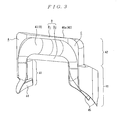
- FIG. 3 is a perspective view illustrative of a divided body of a rotational part according to the embodiment of the ball screw device of the present invention.
- FIG. 4 is a view of the divided body of the rotational part according to the embodiment of the ball screw device of the present invention when seen from a flat surface direction of a nut.
- FIGS. 5(a) to 5(c) are diagrams of the divided body of a rotational part according to the embodiment of the ball screw device of the present invention, where FIG. 5(a) is seen from arrow Y of FIG. 4 , FIG. 5(b) is seen from arrow X of FIG. 4 , and FIG. 5(c) is seen from the axial direction of a screw shaft.
- a ball screw device 1 has a nut 20, which has a spiral groove 21 inside corresponding to a surface groove 11, fitted to a screw shaft 10 having a spiral groove 11 on the outer surface, and a groove 21 of the nut 20 faces the groove 11 of the screw shaft 10, and a spiral raceway that receives a load is formed between both grooves.
- a part of the peripheral surface of the nut 20 has a flat surface 20a, where recirculating parts 40 are fixed on the flat surface 20a by press-down fittings 50 and setscrews 60, for example.
- Each of the recirculating parts 40 is formed by including a pair of legs 41 and a main body 42 connecting the pair of legs 41, having its own interior made as a ball recirculating path R, and joining together the divided faces of divided bodies 40a (see FIG. 3 ), which are divided in two point symmetrically along the ball recirculating path R.
- a circulating groove 43 constituting the ball recirculating path R is formed in the divided faces of the respective divided bodies 40a.
- the pair of legs 41 is spaced from each other axially and radially along the shaft line of the screw shaft 10.
- a tongue portion 44 for scooping up the balls 30 that roll along the spiral raceway between the grooves 11 and 21 in a direction approximately tangential to the spiral raceway is provided at a front edge of the respective legs 41.
- These legs 41 are fitted to a pair of recirculation holes 22 bored in the flat surface 20a of the nut 20 in a direction approximately orthogonal to the centerline of the nut 20 and communicating with the spiral raceway between the grooves 11 and 21.
- the pair of recirculation holes 22 is arranged with axial centers separated the same distance away from the shaft line of the screw shaft 10 in opposite directions therefrom.
- a relief 45 (see FIG. 3 ) for preventing the front edge of the leg 41 on the side, where the tongue portion 44 of the divided body 40a of the recirculating part 40 is not provided, from touching the screw shaft 10 is formed on that front edge of the leg 41.
- the recirculating part 40 contributes to formation of an endless spiral raceway for the balls 30, which roll along the spiral raceway between the grooves 11 and 21, are scooped up and led to the inside of the main body 42 outside of the nut 20, and are then returned to the spiral raceway from the other leg 41.
- the ball recirculating path R within the recirculating part 40 has a first curvature portion R1, which leads the scooped-up balls 30 to the outside of the nut 20 in the direction having a predetermined angle or approximately coinciding with the axial direction of each recirculation hole 22, a second curvature portion R2, which leads the balls 30 having passed the first curvature portion R1 to the other leg 41, a third curvature portion R3, which leads the balls 30 having passed the second curvature portion R2 to the inside of the other leg 41 via the main body 42, and a fourth curvature portion R4, which leads the balls 30 having passed the third curvature portion R3 to the position of the tongue 44 of the other leg 41.
- the recirculating part 40 is divided into two point symmetrically along the ball recirculating path R at a position but the respective tongue portions 44 of the pair of legs 41. More specifically, as shown in FIG. 3 to FIG. 5 , a first divided face A and a first divided face C, which divides the legs 41, of divided faces of the recirculating part 40 (divided body 40a) are divided so as to be approximately orthogonal to a flat surface (flat surface including a group of normal lines for the central centerline of the ball recirculating path R at the respective curved portions : surface along the page top of FIG. 5(b) ) including the central centerline of the ball recirculating path R at the first curvature portion R1 and the fourth curvature portion R4.
- a second divided face B which divides the main body 42, of the divided faces of the recirculating part 40 (divided body 40a) has a divided face B 1 and a divided face B 2 .
- the divided face B 1 and the divided face B 2 are each divided in a direction joining the divided face A and the divided face C, passing through the path center 72 of FIG. 5(a) .
- reference numeral 70 denotes a ball scooping position of one leg
- 71 denotes a ball scooping position of the other leg
- 72 denotes a midpoint of the ball recirculating path R
- 73 denotes the centerline of the ball recirculating path R
- K denotes the ball center trajectory on the spiral raceway (load zone).
- the ball recirculating path R within the recirculating part 40 will be described with progression of the ball 30 while referencing FIG. 4 and FIG. 5 .
- the screw shaft 10 is assumed to rotate clockwise when seen axially, as shown in FIG. 5(c) .
- the ball 30 that has rolled between the grooves 11 and 21 along the spiral raceway or load zone is scooped up approximately tangential to the spiral raceway at the ball scooping position 70 of the one leg 41 by the tongue 44, veers off from the spiral raceway, and enters the ball recirculating path R, where ⁇ in FIG. 5(c) is an apparent scooping angle for obtaining a load capacity, and is set to be greater than 0 and less then or equal to 90° (actually approximately 20 to 45°).
- the ball 30 that has moved from the ball scooping position 70 to the ball recirculating path R changes traveling direction along the first curvature portion R1 within the ball recirculating path R to approximately the same direction as the axial direction of the recirculation holes 22, namely direction of the main body 42 of the recirculating part 40.
- the ball 30 that passes the first curvature portion R1 and travels toward the recirculating part 40 changes to face the other leg 41 along the second curvature portion R2, passes along the ball recirculating path R within the main body 42 of the recirculating part 40, and reaching the midpoint 72 of the ball recirculating path R.
- the recirculating path from the midpoint 72 of the ball recirculating path R to the third curvature portion R3, the fourth curvature portion R4, and reaching the ball returning position 71 of the other leg 41 has a point symmetric form to the path ranging from the ball returning position 70 of the one leg 41 to the midpoint 72 of the ball recirculating path R.
- the recirculating path R within the recirculating part 40 has the first curvature portion R1 (or the fourth curvature portion R4), which leads the ball 30 scooped up from the spiral raceway by the tongue portion 44 of the one leg 41 of the pair of legs 41 to the outside of the nut 20 in a direction approximately the same as the axial direction of the recirculation holes.
- This allows a smaller recirculation hole 22 than when the portion of the first curvature portion R1 (or the fourth curvature portionR4) is a straight line, and an apparent scooping angle ⁇ for obtaining a load capacity may thus be provided without needlessly increasing the size of recirculation hole 22.
- the travelling direction of the ball 30 after it has passed the first curvature portion R1 need not always be along the centerline of the recirculation hole 22, but between the first curvature portion R1 and the second curvature portion R2 or inflexion points of the respective curvature portions, and between the third curvature portion R3 and the fourth curvature portion R4 or inflexion points of the respective curvature portions, it may be at a slant so that the angle formed by the travelling direction of the ball 30 and the centerline of the recirculation hole 22 is 0° or greater and less than the apparent scooping angle ⁇ .
- recirculation holes 22 of the nut 20 may be round holes, it is preferable that they are holes having a longer dimension than the width of an oval, ellipse, or the like, and that the longitudinal direction thereof is approximately along the spiral raceway between the grooves 11 and 21.
- Forming such recirculation hole 22 allows prevention of interference of the recirculation holes 22 to the adjacent groove 21 in the load zone even with a ball screw device having adjacent grooves 21, such as a ball screw device with a small lead or a multithread ball screw device.
- the divided faces of the respective divided bodies 40a which result from dividing the recirculating part 40 into two along the recirculating path R, are a first divided face A of the one leg 41 including an end of the main body 42, a first divided face C of the other leg 41 including an end of the main body 42, and a second divided face B of the intermediate portion of the main body 42.
- the first divided face A is a flat surface approximately orthogonal to a flat surface including the central centerline of the ball recirculating path R at the first curvature portion R1 (i.e., flat surface including a group of normal lines for the central centerline of the ball recirculating path R at the curvature portion R1: surface along the page top of FIG. 5(b) ).
- the first divided face A may thus prevent reduction in the strength of the tongue portions 44 without unequally dividing the tongue portions 44 and the legs 41 connected to the tongue portions 44.
- the first divided face C is adjacent to the first divided face A when the two divided bodies 40a are fitted point symmetrically.
- the second divided face B is a face joining the first divided face A and the first divided face C, and is constituted by an upper side divided face B 1 and a lower side divided face B 2 orthogonal to each other when viewed from the flat surface 20a in a state where the recirculating part 40 is fixed to the flat surface 20a of the nut 20.
- the divided face B 1 in the illustrated example includes the central centerline of the ball recirculating path R.
- the ball centerline 73 within the ball recirculating path R and either one or both (one in this example) of the divided face B 1 and the divided face B 2 intersect at the midpoint 72 of the ball recirculating path R.
- the intersecting angle ⁇ of the divided face B 1 and the divided face B 2 is greater than 0° and less than 90°, preferably 45° or less. Note that the divided face B 1 in the illustrated example coincides with the central centerline 73 of the ball recirculating path R.
- uniform division of the ball recirculating path R throughout the entire path allows smoother circulation of the ball 30.
- application of the recirculating part 40 having such a configuration to a ball screw device having a lead angle of 4° or less and less than 2.5 rolls exerts particularly remarkable effects.
- a bending portion 80 may be provided at the base of the tongue portion 44 at the first divided face A, as shown in FIG. 5(c) .
- This bending portion 80 allows division of the recirculating part 40 without any concern regarding the strength around the tongue portion 44.
- a bending portion 81 is also provided on the first divided face C side so as not to interfere with the bending portion 80 of the fist divided face A.
- the recirculating part 40 may be fixed directly to the flat surface 20a of the nut 20 by setscrews or the like instead of using the press-down fittings 50.
- Material, form, size, mode, number, arrangement and the like of the grooves, screw shaft, nut, balls, recirculation holes, ball recirculating paths, rotational parts, tongue portions, legs, main body, first curvature portion, second curvature portion, third curvature portion, fourth curvature portion, etc. illustrated in the embodiment described above are arbitrary and are not limited as long as they allow accomplishing the aim of the present invention.
Landscapes
- Engineering & Computer Science (AREA)
- General Engineering & Computer Science (AREA)
- Mechanical Engineering (AREA)
- Transmission Devices (AREA)
Abstract
Description
- The present invention relates to a ball screw device usable for various kinds of machinery such as machine tools, injection molding machines, etc., more particularly to a ball screw device including a tubular rotational part.
- A ball screw device according to
Patent Document 1 is disclosed as this type of conventional ball screw device. The ball screw device disclosed inPatent Document 1 results from dividing a resin rotational part (not shown) into two parts and arranging them such that the centerlines of recirculating paths within legs of the rotational part fitted to recirculation holes of a nut approximately coincide tangentially (approximately tangential to a spiral raceway) and in a lead angle direction of both grooves so as to provide smooth scooping up of balls (rolling elements). - However, since the ball screw device disclosed in
Patent Document 1 has the rotational part divided into two parts radially along the centerlines of the ball recirculating paths, even a tongue portion for scooping up the balls is divided, and there is concern that the strength of the tongue portion will be reduced. - Therefore, the ball screw device of Patent Document 2, which avoids such division of the tongue portion, has been disclosed.
-
FIG. 6 is a diagram illustrative of a configuration of the conventional ball screw device disclosed in Patent Document 2, whereFIG. 6(a) is a top view andFIG. 6(b) is a view of a rotational part when seen from the axial direction of a screw shaft. As shown inFIGS. 6(a) and 6(b) , aball screw device 101 disclosed in Patent Document 2 has anut 120 including a spiral groove (not shown) corresponding to aninner surface groove 111 fitted to ascrew shaft 110 including a spiralexternal surface groove 111. Multiple balls (not shown) are loaded in a rollable fashion along a spiral raceway K between thegrooves 111 and the groove of thenut 120. - Moreover, a
flat surface 120a is formed on the peripheral surface of thenut 120, and two pairs ofrecirculation holes 122 passing to the spiral raceway K are bored in theflat surface 120a. Arecirculating part 140 is established so that both ends are fitted to the pairs ofrecirculation holes 122, forming a ball recirculating path where the balls are lead to the outside of thenut 120 through one of therecirculation holes 122 and then back to the spiral track K through the other of therecirculation holes 122. Therecirculating part 140 is comprised by a pair oflegs 141, each having atongue portion 144 for scooping up the balls that roll along the spiral raceway K on ends thereof in a direction approximately tangential to the spiral raceway K, and amain body 142 connecting the pair oflegs 141. Furthermore, therecirculating part 140 is formed including the pair oflegs 141 and themain body 142 connecting the pair oflegs 141, the interior made as a ball recirculating path R, and dividedbodies 140a, which are divided in two point symmetrically along the ball recirculating path R, fitted by divided faces. Circulatinggrooves 143 constituting the ball recirculating path R are formed in the divided faces of the respective dividedbodies 140a. - The circulating
grooves 143 constituting the ball recirculating path R each includes a first curvature portion R1, a second curvature portion R2, a third curvature portion R3, and a fourth curvature portion R4. The first curvature portion R1 is a portion leading a ball, which is scooped up from the spiral raceway K by thetongue 144 of oneleg 141 of the pair oflegs nut 120 in a direction having a predetermined angle or approximately coinciding with the axial direction of therecirculation hole 122. The second curvature portion R2 is a portion leading the ball having passed the first curvature portion R1 to theother leg 141. The third curvature portion R3 is a portion leading the ball having passed the second curvature portion R2 to the inside of theother leg 141 via themain body 142. The fourth curvature portion R4 is a portion leading the ball having passed the third curvature portion R3 to the position of thetongue portion 144 of theother leg 141. -
- Patent Document 1:
US Patent 2851897 Specification - Patent Document 2:
JP 2006-125581A - However, the rotational part according to the ball screw device of Patent Document 2, when applied to a ball screw device having a small lead angle and a small number of circulation rolls, there is a chance that unequal division of the tongue portions or the legs connected to the tongue portions is inevitable if prevention of loss of the ball recirculating path R is attempted. More specifically, as shown in
FIGS. 7 (a) and 7 (b) , if the number of circulation rolls of the ball screw device is 2.5 rolls, dividedbodies 140a formed with a proper ball recirculating path R without dividing unequally thetongue portions 144 and thelegs 141 connected to thetongue portions 144 may be fabricated. On the other hand, if the number of circulation rolls of the ball screw device becomes small (1.5 rolls, for example) as shown inFIGS. 7(c) and 7(d) , angle ψ formed by a cross-sectional surface B of the dividedbody 140a in the axial direction of thenut 120 increases, and the ball recirculating path R at point D is lost. In other words, with a ball screw device having a small lead angle and a small number of circulation rolls, there are cases where fabrication of the dividedbody 140a having a ball recirculating path R formed without dividing unequally thetongue portions 144 and thelegs 141 connected to thetongue portions 144 is impossible. Accordingly, with a ball screw device having a small lead angle and a small number of circulation rolls, due to reduction in the strength of thetongue portions 144 as a result of unequal division of thetongue portions 144 and thelegs 141 connected to thetongue portions 144 being inevitable, there is room for improvement thereof. - Therefore, the present invention is made in light of such a problem, and aims to provide a ball screw device capable of keeping unequal division of tongue portions and legs connected to the tongue portions to a minimum, securing the strength of the tongue portions, and evenly divide and form circulating paths in order to circulate balls more smoothly even if the lead angle and the number of circulation rolls is low.
- A ball screw device according to an embodiment of the present invention in order to solve the aforementioned problem includes: a screw shaft having a spiral groove on the outer surface; a nut having on the inner surface a spiral groove corresponding to the groove of the screw shaft and screwed with the screw shaft; a plurality of balls loaded in a rollable fashion along a spiral raceway between both of the grooves; and a rotational part having both ends fitted to respective recirculation holes of a pair of recirculation holes formed in a flat surface, which is bored on a circumferential side surface of the nut, in a direction approximately orthogonal to an centerline of the nut, so as to create a ball recirculating path for leading the plurality of balls rolling along the spiral raceway to the outside of the nut from one recirculation hole of the pair of recirculation holes, and returning the plurality of balls to the spiral raceway from the other recirculation hole.
- The rotational part includes a pair of legs that include a tongue portion for scooping up the balls that roll along the spiral raceway on the ends of the legs in a direction approximately tangential to the spiral raceway and that have both ends fitted to the recirculation holes of the nut, and a main body connecting the pair of legs.
- It also has a first divided face for dividing the pair of legs along the ball recirculating path, and a second divided face for dividing the main body along the ball recirculating path; wherein the second divided face is formed such that an upper divided face and a lower divided face of the ball recirculating path intersect with each other when viewed from the flat surface of the nut.
- According to the ball screw device according to the embodiment of the present invention, a ball screw device is provided capable of keeping unequal division of tongue portions and legs connected to the tongue portions to a minimum, securing the strength of the tongue portions, and evenly divide and form circulating paths in order to circulate balls more smoothly even if the lead angle and the number of circulation rolls is low.
-
-
FIG. 1 is a top view of an embodiment of a ball screw device according to the present invention; -
FIG. 2 is a right side view ofFIG. 1 ; -
FIG. 3 is a perspective view illustrative of a divided body of a rotational part according to the embodiment of the ball screw device of the present invention; -
FIG. 4 is a view of the divided body of the rotational part according to the embodiment of the ball screw device of the present invention when seen from a flat surface direction of a nut; -
FIGS. 5(a), 5(b) and 5(c) are diagrams of the divided body of a rotational part according to the embodiment of the ball screw device of the present invention, whereFIG. 5(a) is seen from arrow Y ofFIG. 4 ,FIG. 5(b) is seen from arrow X ofFIG. 4 , andFIG. 5(c) is seen from the axial direction of a screw shaft (when seen from the opposite direction to the arrow X direction ofFIG. 4 ); -
FIGS. 6(a) and 6(b) are diagrams illustrative of a configuration of a conventional ball screw device, whereFIG. 6(a) is a top view andFIG. 6(b) is a view of a rotational part when seen from the axial direction of a screw shaft; and -
FIGS. 7 (a) to 7 (d) are diagrams of a divided body of the conventional rotational part, whereFIG. 7(a) is a diagram of the rotational part with 2.5 rolls when seen from a flat surface direction of a nut,FIG. 7 (b) is seen from arrow Z ofFIG. 7 (a), FIG. 7 (c) is a diagram of the rotational part with 1.5 rolls when seen from a flat surface direction of a nut, andFIG. 7 (d) is seen from arrow Z ofFIG. 7(c) . - A ball screw device of an embodiment of the present invention will now be described with reference to the drawings.
-
FIG. 1 is a top view of an embodiment of a ball screw device according to the present invention.FIG. 2 is a right side view ofFIG. 1 .FIG. 3 is a perspective view illustrative of a divided body of a rotational part according to the embodiment of the ball screw device of the present invention.FIG. 4 is a view of the divided body of the rotational part according to the embodiment of the ball screw device of the present invention when seen from a flat surface direction of a nut.FIGS. 5(a) to 5(c) are diagrams of the divided body of a rotational part according to the embodiment of the ball screw device of the present invention, whereFIG. 5(a) is seen from arrow Y ofFIG. 4 ,FIG. 5(b) is seen from arrow X ofFIG. 4 , andFIG. 5(c) is seen from the axial direction of a screw shaft. - As shown in
FIGS. 1 and 2 , aball screw device 1 has anut 20, which has aspiral groove 21 inside corresponding to asurface groove 11, fitted to ascrew shaft 10 having aspiral groove 11 on the outer surface, and agroove 21 of thenut 20 faces thegroove 11 of thescrew shaft 10, and a spiral raceway that receives a load is formed between both grooves. -
Multiple balls 30 as rolling elements are loaded in a rollable fashion along the spiral raceway, and thenut 20 is moved axially via rolling of theballs 30 by rotation of the screw shaft 10 (or the nut 20). - A part of the peripheral surface of the
nut 20 has aflat surface 20a, whererecirculating parts 40 are fixed on theflat surface 20a by press-downfittings 50 andsetscrews 60, for example. - Each of the
recirculating parts 40 is formed by including a pair oflegs 41 and amain body 42 connecting the pair oflegs 41, having its own interior made as a ball recirculating path R, and joining together the divided faces of dividedbodies 40a (seeFIG. 3 ), which are divided in two point symmetrically along the ball recirculating path R. A circulatinggroove 43 constituting the ball recirculating path R is formed in the divided faces of the respective dividedbodies 40a. - This allows easy assembly of the recirculating
parts 40 by joining together two of the dividedbodies 40a of the same shape, and reduction in cost due to use of only one kind of molding die for thedivided bodies 40a. Note that in this embodiment, two of the recirculatingparts 40 are arranged to form two circulation circuits. - The pair of
legs 41 is spaced from each other axially and radially along the shaft line of thescrew shaft 10. Atongue portion 44 for scooping up theballs 30 that roll along the spiral raceway between thegrooves respective legs 41. - These
legs 41 are fitted to a pair ofrecirculation holes 22 bored in theflat surface 20a of thenut 20 in a direction approximately orthogonal to the centerline of thenut 20 and communicating with the spiral raceway between thegrooves recirculation holes 22 is arranged with axial centers separated the same distance away from the shaft line of thescrew shaft 10 in opposite directions therefrom. Note that a relief 45 (seeFIG. 3 ) for preventing the front edge of theleg 41 on the side, where thetongue portion 44 of the dividedbody 40a of therecirculating part 40 is not provided, from touching thescrew shaft 10 is formed on that front edge of theleg 41. - The
recirculating part 40 contributes to formation of an endless spiral raceway for theballs 30, which roll along the spiral raceway between thegrooves main body 42 outside of thenut 20, and are then returned to the spiral raceway from theother leg 41. - In this embodiment, with reference to
FIGS. 5(b) and 5(c) , the ball recirculating path R within therecirculating part 40 has a first curvature portion R1, which leads the scooped-upballs 30 to the outside of thenut 20 in the direction having a predetermined angle or approximately coinciding with the axial direction of eachrecirculation hole 22, a second curvature portion R2, which leads theballs 30 having passed the first curvature portion R1 to theother leg 41, a third curvature portion R3, which leads theballs 30 having passed the second curvature portion R2 to the inside of theother leg 41 via themain body 42, and a fourth curvature portion R4, which leads theballs 30 having passed the third curvature portion R3 to the position of thetongue 44 of theother leg 41. - Moreover, the
recirculating part 40 is divided into two point symmetrically along the ball recirculating path R at a position but therespective tongue portions 44 of the pair oflegs 41. More specifically, as shown inFIG. 3 to FIG. 5 , a first divided face A and a first divided face C, which divides thelegs 41, of divided faces of the recirculating part 40 (dividedbody 40a) are divided so as to be approximately orthogonal to a flat surface (flat surface including a group of normal lines for the central centerline of the ball recirculating path R at the respective curved portions : surface along the page top ofFIG. 5(b) ) including the central centerline of the ball recirculating path R at the first curvature portion R1 and the fourth curvature portion R4. Furthermore, a second divided face B, which divides themain body 42, of the divided faces of the recirculating part 40 (dividedbody 40a) has a divided face B1 and a divided face B2. The divided face B1 and the divided face B2 are each divided in a direction joining the divided face A and the divided face C, passing through thepath center 72 ofFIG. 5(a) . - The rotational part (divided body) will now be described with reference to
FIG. 3 to FIG. 5 . Note that inFIG. 4 andFIG. 5 ,reference numeral 70 denotes a ball scooping position of one leg, 71 denotes a ball scooping position of the other leg, 72 denotes a midpoint of the ball recirculating path R, 73 denotes the centerline of the ball recirculating path R, and K denotes the ball center trajectory on the spiral raceway (load zone). When aball 30 is scooped up on the oneleg 41 side, theball scooping position 71 functions as a ball returning position, and when theball 30 is scooped up on theother leg 41 side, theball scooping position 70 functions as a ball returning position. The case of scooping up the ball on the oneleg 41 side will be described next. - First, the ball recirculating path R within the
recirculating part 40 will be described with progression of theball 30 while referencingFIG. 4 andFIG. 5 . In this case, thescrew shaft 10 is assumed to rotate clockwise when seen axially, as shown inFIG. 5(c) . - The
ball 30 that has rolled between thegrooves ball scooping position 70 of the oneleg 41 by thetongue 44, veers off from the spiral raceway, and enters the ball recirculating path R, where θ inFIG. 5(c) is an apparent scooping angle for obtaining a load capacity, and is set to be greater than 0 and less then or equal to 90° (actually approximately 20 to 45°). - The
ball 30 that has moved from theball scooping position 70 to the ball recirculating path R changes traveling direction along the first curvature portion R1 within the ball recirculating path R to approximately the same direction as the axial direction of the recirculation holes 22, namely direction of themain body 42 of therecirculating part 40. - The
ball 30 that passes the first curvature portion R1 and travels toward therecirculating part 40 changes to face theother leg 41 along the second curvature portion R2, passes along the ball recirculating path R within themain body 42 of therecirculating part 40, and reaching themidpoint 72 of the ball recirculating path R. - The recirculating path from the
midpoint 72 of the ball recirculating path R to the third curvature portion R3, the fourth curvature portion R4, and reaching theball returning position 71 of theother leg 41 has a point symmetric form to the path ranging from theball returning position 70 of the oneleg 41 to themidpoint 72 of the ball recirculating path R. - In this manner, the recirculating path R within the
recirculating part 40 has the first curvature portion R1 (or the fourth curvature portion R4), which leads theball 30 scooped up from the spiral raceway by thetongue portion 44 of the oneleg 41 of the pair oflegs 41 to the outside of thenut 20 in a direction approximately the same as the axial direction of the recirculation holes. This allows asmaller recirculation hole 22 than when the portion of the first curvature portion R1 (or the fourth curvature portionR4) is a straight line, and an apparent scooping angle θ for obtaining a load capacity may thus be provided without needlessly increasing the size ofrecirculation hole 22. - As a result, scooping up of the
ball 30 in a direction approximately tangential to the spiral raceway may be easily carried out, interference of the recirculation holes 22 of thenut 20 to thegroove 21 in the load zone may be prevented while keeping the apparent scooping angle θ for obtaining a load capacity, and multiple circulation circuits may be provided to asingle nut 20 without excessively lengthening the entire length of thenut 20. - Note that the travelling direction of the
ball 30 after it has passed the first curvature portion R1 need not always be along the centerline of therecirculation hole 22, but between the first curvature portion R1 and the second curvature portion R2 or inflexion points of the respective curvature portions, and between the third curvature portion R3 and the fourth curvature portion R4 or inflexion points of the respective curvature portions, it may be at a slant so that the angle formed by the travelling direction of theball 30 and the centerline of therecirculation hole 22 is 0° or greater and less than the apparent scooping angle θ. - Slanting the travelling direction (direction of the recirculating path R) of the
ball 30 relative to the centerline of therecirculation hole 22 of thenut 20 in this manner once it has passed the first curvature portion R1 allows increase in bending R of the first curvature portion R1 and the second curvature portion R2, thereby allowing reduction in centrifugal force of theball 30 at the time of passing the first curvature portion R1 so as to prevent wear or damage of therecirculating part 40 due to the centrifugal force and make circulation of theball 30 smoother. - Moreover, while the recirculation holes 22 of the
nut 20 may be round holes, it is preferable that they are holes having a longer dimension than the width of an oval, ellipse, or the like, and that the longitudinal direction thereof is approximately along the spiral raceway between thegrooves - Forming
such recirculation hole 22 allows prevention of interference of the recirculation holes 22 to theadjacent groove 21 in the load zone even with a ball screw device havingadjacent grooves 21, such as a ball screw device with a small lead or a multithread ball screw device. - The configuration of the
aforementioned recirculating part 40 having the recirculating path R and the dividedbodies 40a constituting therecirculating part 40 will be described next. - As shown in
FIG. 3 andFIG. 4 , the divided faces of the respective dividedbodies 40a, which result from dividing therecirculating part 40 into two along the recirculating path R, are a first divided face A of the oneleg 41 including an end of themain body 42, a first divided face C of theother leg 41 including an end of themain body 42, and a second divided face B of the intermediate portion of themain body 42. - The first divided face A is a flat surface approximately orthogonal to a flat surface including the central centerline of the ball recirculating path R at the first curvature portion R1 (i.e., flat surface including a group of normal lines for the central centerline of the ball recirculating path R at the curvature portion R1: surface along the page top of
FIG. 5(b) ). The first divided face A may thus prevent reduction in the strength of thetongue portions 44 without unequally dividing thetongue portions 44 and thelegs 41 connected to thetongue portions 44. The first divided face C is adjacent to the first divided face A when the two dividedbodies 40a are fitted point symmetrically. - The second divided face B is a face joining the first divided face A and the first divided face C, and is constituted by an upper side divided face B1 and a lower side divided face B2 orthogonal to each other when viewed from the
flat surface 20a in a state where therecirculating part 40 is fixed to theflat surface 20a of thenut 20. Moreover, the divided face B1 in the illustrated example includes the central centerline of the ball recirculating path R. The ball centerline 73 within the ball recirculating path R and either one or both (one in this example) of the divided face B1 and the divided face B2 intersect at themidpoint 72 of the ball recirculating path R. The intersecting angle Φ of the divided face B1 and the divided face B2 is greater than 0° and less than 90°, preferably 45° or less. Note that the divided face B1 in the illustrated example coincides with thecentral centerline 73 of the ball recirculating path R. - Furthermore, such a structure of the second divided face B that the divided faces of the respective upper and lower portions of the ball recirculating path R intersect with each other when viewed from the
flat surface 20a of thenut 20 prevents unequal division of thelegs 41 connected to thetongues 44 and allows keeping of the peripheral shape even with a ball screw device having a small lead angle and few circulation rolls. Therefore, the strength of therecirculating part 40 may be secured. Moreover, dividing approximately equally the flat surface of the upper side of themain body 42 and making a fixed pressure of therecirculating part 40 be approximately uniform across the entire fixed region makes elastic deformation at the time of fixation be approximately uniform, thereby making circulation of theball 30 smoother. In addition, uniform division of the ball recirculating path R throughout the entire path allows smoother circulation of theball 30. Note that application of therecirculating part 40 having such a configuration to a ball screw device having a lead angle of 4° or less and less than 2.5 rolls exerts particularly remarkable effects. - Alternatively, when the
tongue portion 44 of the one leg is protruding further than the first divided face A, a bendingportion 80 may be provided at the base of thetongue portion 44 at the first divided face A, as shown inFIG. 5(c) . This bendingportion 80 allows division of therecirculating part 40 without any concern regarding the strength around thetongue portion 44. In this case, a bendingportion 81 is also provided on the first divided face C side so as not to interfere with the bendingportion 80 of the fist divided face A. - Note that the present invention is not limited to the embodiment described above, and may be appropriately modified as long as it does not deviate from the spirit of the present invention.
- For example, while the
recirculating part 40 is fixed on theflat surface 20a of thenut 20 via the press-downfittings 50 in the above embodiment, therecirculating part 40 may be fixed directly to theflat surface 20a of thenut 20 by setscrews or the like instead of using the press-downfittings 50. - Material, form, size, mode, number, arrangement and the like of the grooves, screw shaft, nut, balls, recirculation holes, ball recirculating paths, rotational parts, tongue portions, legs, main body, first curvature portion, second curvature portion, third curvature portion, fourth curvature portion, etc. illustrated in the embodiment described above are arbitrary and are not limited as long as they allow accomplishing the aim of the present invention.
-
- 1: Ball screw device
- 10: Screw shaft
- 11: Groove
- 20: Nut
- 21: Groove
- 22: Recirculation holes
- 30: Ball
- 40: Recirculating parts
- 41: Legs
- 42: Main body
- R: Ball recirculating path
- R1: First curvature portion
- R2: Second curvature portion
- R3: Third curvature portion
- R4: Fourth curvature portion
- A: First divided face
- B: Second divided face
- B1: Upper divided face of the second divided face B on the ball recirculating path R
- B2: Lower divided face of the second divided face B on the ball recirculating path R
- C: First divided face
Claims (1)
- A ball screw device, comprising:a screw shaft having a spiral groove on an outer surface;a nut having on an inner surface a spiral groove corresponding to the groove of the screw shaft and screwed with the screw shaft;a plurality of balls loaded in a rollable fashion along a spiral raceway between both of the grooves; anda rotational part having both ends fitted to respective recirculation holes of a pair of recirculation holes formed in a flat surface, which is bored on a circumferential side surface of the nut, in a direction approximately orthogonal to an centerline of the nut, so as to create a ball recirculating path for leading the plurality of balls rolling along the spiral raceway to the outside of the nut from one recirculation hole of the pair of recirculation holes, and returning the plurality of balls to the spiral raceway from the other recirculation hole, wherein
the rotational part comprises a pair of legs that include a tongue portion for scooping up the balls that roll along the spiral raceway on the ends of the legs in a direction approximately tangential to the spiral raceway and that have both ends fitted to the recirculation holes of the nut, and a main body connecting the pair of legs,
and further comprises a first divided face for dividing the pair of legs along the ball recirculating path, and a second divided face for dividing the main body along the ball recirculating path;
wherein the second divided face is formed such that an upper divided face and a lower divided face of the ball recirculating path intersect with each other when viewed from the flat surface of the nut.
Applications Claiming Priority (2)
| Application Number | Priority Date | Filing Date | Title |
|---|---|---|---|
| JP2010273685 | 2010-12-08 | ||
| PCT/JP2011/000624 WO2012077247A1 (en) | 2010-12-08 | 2011-02-03 | Ball screw device |
Publications (3)
| Publication Number | Publication Date |
|---|---|
| EP2650563A1 true EP2650563A1 (en) | 2013-10-16 |
| EP2650563A4 EP2650563A4 (en) | 2016-09-07 |
| EP2650563B1 EP2650563B1 (en) | 2020-03-25 |
Family
ID=46206765
Family Applications (1)
| Application Number | Title | Priority Date | Filing Date |
|---|---|---|---|
| EP11702382.0A Active EP2650563B1 (en) | 2010-12-08 | 2011-02-03 | Ball screw device |
Country Status (5)
| Country | Link |
|---|---|
| US (1) | US9003911B2 (en) |
| EP (1) | EP2650563B1 (en) |
| JP (1) | JP5500268B2 (en) |
| CN (1) | CN102652232B (en) |
| WO (1) | WO2012077247A1 (en) |
Families Citing this family (9)
| Publication number | Priority date | Publication date | Assignee | Title |
|---|---|---|---|---|
| US9003911B2 (en) * | 2010-12-08 | 2015-04-14 | Nsk Ltd. | Ball screw device |
| JP6257352B2 (en) | 2014-01-31 | 2018-01-10 | Thk株式会社 | Ball screw |
| JP5818925B2 (en) * | 2014-02-13 | 2015-11-18 | Thk株式会社 | Ball screw device |
| JP5782199B1 (en) * | 2014-08-12 | 2015-09-24 | 黒田精工株式会社 | Ball screw |
| DE102015214856B4 (en) * | 2015-08-04 | 2017-07-06 | Schaeffler Technologies AG & Co. KG | Ball Screw |
| EP3540263B1 (en) * | 2016-11-14 | 2023-11-22 | NSK Ltd. | Ball screw |
| CN108386506A (en) * | 2017-01-24 | 2018-08-10 | 上银科技股份有限公司 | external circulation type ball screw |
| CN107806498A (en) * | 2017-11-08 | 2018-03-16 | 山东交通学院 | A kind of electromagnetic damper feed screw apparatus |
| US11680628B2 (en) * | 2020-04-02 | 2023-06-20 | Nsk Ltd. | Ball screw device |
Family Cites Families (25)
| Publication number | Priority date | Publication date | Assignee | Title |
|---|---|---|---|---|
| US2851897A (en) | 1957-03-05 | 1958-09-16 | Alfred P M Cochrane | Screw and nut assembly |
| CN2106939U (en) * | 1991-08-05 | 1992-06-10 | 邓隽钧 | Reversal rolling screw pair |
| DE4238910A1 (en) * | 1992-11-19 | 1994-05-26 | Schaeffler Waelzlager Kg | Wiper unit for a linear roller bearing element |
| JP3515126B2 (en) * | 1996-06-21 | 2004-04-05 | Thk株式会社 | Ball screw device |
| JP4294115B2 (en) * | 1998-03-25 | 2009-07-08 | Thk株式会社 | Ball screw device |
| JP4220018B2 (en) * | 1998-06-26 | 2009-02-04 | Thk株式会社 | Ball screw |
| JP3948973B2 (en) * | 2002-02-07 | 2007-07-25 | Thk株式会社 | Screw device with lubricant application function |
| US20030172759A1 (en) * | 2002-02-25 | 2003-09-18 | Nsk Ltd. | Ball screw |
| JP4053826B2 (en) * | 2002-06-25 | 2008-02-27 | Thk株式会社 | Circulating component, and motion guide device and ball screw using the circulating component |
| JP2004108454A (en) * | 2002-09-17 | 2004-04-08 | Nsk Ltd | Tube guide for ball screw, ball screw, and method of manufacturing ball screw |
| JP2004353835A (en) * | 2003-05-30 | 2004-12-16 | Koyo Seiko Co Ltd | Ball screw and electric power steering using the same |
| DE10354064A1 (en) * | 2003-11-19 | 2005-06-02 | Ina-Schaeffler Kg | Roller screw |
| JP2006046530A (en) * | 2004-08-05 | 2006-02-16 | Nsk Ltd | Ball screw device |
| EP1624228B1 (en) | 2004-08-06 | 2011-10-12 | NSK Ltd. | Ball circulating member and ball screw |
| JP4525233B2 (en) * | 2004-08-06 | 2010-08-18 | 日本精工株式会社 | Ball circulation member and ball screw |
| JP2006125581A (en) | 2004-10-29 | 2006-05-18 | Nsk Ltd | Ball screw device |
| US20080190231A1 (en) * | 2005-12-01 | 2008-08-14 | Yueh Ling Chiu | Ball screw device having ball guide member |
| US7520193B2 (en) * | 2006-03-06 | 2009-04-21 | Hiwin Technologies Corp. | Ball screw assembly |
| JP5226671B2 (en) * | 2007-03-30 | 2013-07-03 | Thk株式会社 | Roller screw |
| US7516681B2 (en) * | 2007-07-13 | 2009-04-14 | Hiwin Technologies Corp. | External circulation type ball screw |
| JP2010038196A (en) * | 2008-07-31 | 2010-02-18 | Thk Co Ltd | Screw device |
| TWI368697B (en) * | 2008-10-31 | 2012-07-21 | Hiwin Tech Corp | Circulation element for ball screw |
| JP4861395B2 (en) * | 2008-12-24 | 2012-01-25 | 上銀科技股▲分▼有限公司 | Ball external circulation ball screw |
| JP3150527U (en) * | 2009-03-03 | 2009-05-21 | Thk株式会社 | Rolling element screw device |
| US9003911B2 (en) * | 2010-12-08 | 2015-04-14 | Nsk Ltd. | Ball screw device |
-
2011
- 2011-02-03 US US13/059,512 patent/US9003911B2/en active Active
- 2011-02-03 WO PCT/JP2011/000624 patent/WO2012077247A1/en not_active Ceased
- 2011-02-03 JP JP2012547669A patent/JP5500268B2/en active Active
- 2011-02-03 CN CN201180000030.7A patent/CN102652232B/en active Active
- 2011-02-03 EP EP11702382.0A patent/EP2650563B1/en active Active
Also Published As
| Publication number | Publication date |
|---|---|
| US9003911B2 (en) | 2015-04-14 |
| WO2012077247A1 (en) | 2012-06-14 |
| US20130239725A1 (en) | 2013-09-19 |
| CN102652232A (en) | 2012-08-29 |
| EP2650563B1 (en) | 2020-03-25 |
| EP2650563A4 (en) | 2016-09-07 |
| CN102652232B (en) | 2015-01-21 |
| JPWO2012077247A1 (en) | 2014-05-19 |
| JP5500268B2 (en) | 2014-05-21 |
Similar Documents
| Publication | Publication Date | Title |
|---|---|---|
| EP2650563B1 (en) | Ball screw device | |
| US6675669B2 (en) | Ball screw apparatus | |
| US20100242651A1 (en) | Rolling-element screw device | |
| US8220353B2 (en) | Screw device manufacturing method and screw device | |
| US20180010637A1 (en) | Rolling bearing | |
| US8746102B2 (en) | Ball screw device | |
| US9599202B2 (en) | Internal recirculation insert for a ball screw and ball screw assembly including the insert | |
| TWI651478B (en) | Ball screw | |
| JPWO2023145595A5 (en) | ||
| US20040123691A1 (en) | Ball screw apparatus | |
| US9188210B2 (en) | External circulation type ball screw device | |
| KR100703243B1 (en) | Ball screw | |
| JP2005188720A (en) | Ball spline | |
| JP4525233B2 (en) | Ball circulation member and ball screw | |
| JP3726471B2 (en) | Ball screw | |
| US10436300B2 (en) | Offset preload ball screw with expandable loading area | |
| US20070221002A1 (en) | Roller screw mechanism | |
| US20240255044A1 (en) | Ball screw apparatus | |
| JP6083146B2 (en) | Ball screw deflector and deflector ball screw | |
| JP4110834B2 (en) | Ball screw | |
| US20160061303A1 (en) | Offset preload ball screw with expandable loading area | |
| KR200491302Y1 (en) | Ball screw | |
| CN207212942U (en) | Roller spline group | |
| US9556908B2 (en) | Cage element for rolling bearing assembly | |
| JP2012137154A (en) | Ball screw circulation part and ball screw |
Legal Events
| Date | Code | Title | Description |
|---|---|---|---|
| PUAI | Public reference made under article 153(3) epc to a published international application that has entered the european phase |
Free format text: ORIGINAL CODE: 0009012 |
|
| 17P | Request for examination filed |
Effective date: 20110214 |
|
| AK | Designated contracting states |
Kind code of ref document: A1 Designated state(s): AL AT BE BG CH CY CZ DE DK EE ES FI FR GB GR HR HU IE IS IT LI LT LU LV MC MK MT NL NO PL PT RO RS SE SI SK SM TR |
|
| DAX | Request for extension of the european patent (deleted) | ||
| RA4 | Supplementary search report drawn up and despatched (corrected) |
Effective date: 20160804 |
|
| RIC1 | Information provided on ipc code assigned before grant |
Ipc: F16H 25/22 20060101AFI20160729BHEP |
|
| GRAP | Despatch of communication of intention to grant a patent |
Free format text: ORIGINAL CODE: EPIDOSNIGR1 |
|
| STAA | Information on the status of an ep patent application or granted ep patent |
Free format text: STATUS: GRANT OF PATENT IS INTENDED |
|
| INTG | Intention to grant announced |
Effective date: 20190626 |
|
| GRAS | Grant fee paid |
Free format text: ORIGINAL CODE: EPIDOSNIGR3 |
|
| GRAJ | Information related to disapproval of communication of intention to grant by the applicant or resumption of examination proceedings by the epo deleted |
Free format text: ORIGINAL CODE: EPIDOSDIGR1 |
|
| GRAL | Information related to payment of fee for publishing/printing deleted |
Free format text: ORIGINAL CODE: EPIDOSDIGR3 |
|
| STAA | Information on the status of an ep patent application or granted ep patent |
Free format text: STATUS: REQUEST FOR EXAMINATION WAS MADE |
|
| GRAP | Despatch of communication of intention to grant a patent |
Free format text: ORIGINAL CODE: EPIDOSNIGR1 |
|
| STAA | Information on the status of an ep patent application or granted ep patent |
Free format text: STATUS: GRANT OF PATENT IS INTENDED |
|
| INTG | Intention to grant announced |
Effective date: 20191104 |
|
| GRAA | (expected) grant |
Free format text: ORIGINAL CODE: 0009210 |
|
| STAA | Information on the status of an ep patent application or granted ep patent |
Free format text: STATUS: THE PATENT HAS BEEN GRANTED |
|
| AK | Designated contracting states |
Kind code of ref document: B1 Designated state(s): AL AT BE BG CH CY CZ DE DK EE ES FI FR GB GR HR HU IE IS IT LI LT LU LV MC MK MT NL NO PL PT RO RS SE SI SK SM TR |
|
| REG | Reference to a national code |
Ref country code: GB Ref legal event code: FG4D |
|
| REG | Reference to a national code |
Ref country code: AT Ref legal event code: REF Ref document number: 1248918 Country of ref document: AT Kind code of ref document: T Effective date: 20200415 Ref country code: IE Ref legal event code: FG4D |
|
| REG | Reference to a national code |
Ref country code: DE Ref legal event code: R096 Ref document number: 602011065812 Country of ref document: DE |
|
| PG25 | Lapsed in a contracting state [announced via postgrant information from national office to epo] |
Ref country code: NO Free format text: LAPSE BECAUSE OF FAILURE TO SUBMIT A TRANSLATION OF THE DESCRIPTION OR TO PAY THE FEE WITHIN THE PRESCRIBED TIME-LIMIT Effective date: 20200625 Ref country code: FI Free format text: LAPSE BECAUSE OF FAILURE TO SUBMIT A TRANSLATION OF THE DESCRIPTION OR TO PAY THE FEE WITHIN THE PRESCRIBED TIME-LIMIT Effective date: 20200325 Ref country code: RS Free format text: LAPSE BECAUSE OF FAILURE TO SUBMIT A TRANSLATION OF THE DESCRIPTION OR TO PAY THE FEE WITHIN THE PRESCRIBED TIME-LIMIT Effective date: 20200325 |
|
| PG25 | Lapsed in a contracting state [announced via postgrant information from national office to epo] |
Ref country code: BG Free format text: LAPSE BECAUSE OF FAILURE TO SUBMIT A TRANSLATION OF THE DESCRIPTION OR TO PAY THE FEE WITHIN THE PRESCRIBED TIME-LIMIT Effective date: 20200625 Ref country code: GR Free format text: LAPSE BECAUSE OF FAILURE TO SUBMIT A TRANSLATION OF THE DESCRIPTION OR TO PAY THE FEE WITHIN THE PRESCRIBED TIME-LIMIT Effective date: 20200626 Ref country code: SE Free format text: LAPSE BECAUSE OF FAILURE TO SUBMIT A TRANSLATION OF THE DESCRIPTION OR TO PAY THE FEE WITHIN THE PRESCRIBED TIME-LIMIT Effective date: 20200325 Ref country code: LV Free format text: LAPSE BECAUSE OF FAILURE TO SUBMIT A TRANSLATION OF THE DESCRIPTION OR TO PAY THE FEE WITHIN THE PRESCRIBED TIME-LIMIT Effective date: 20200325 Ref country code: HR Free format text: LAPSE BECAUSE OF FAILURE TO SUBMIT A TRANSLATION OF THE DESCRIPTION OR TO PAY THE FEE WITHIN THE PRESCRIBED TIME-LIMIT Effective date: 20200325 |
|
| REG | Reference to a national code |
Ref country code: NL Ref legal event code: MP Effective date: 20200325 |
|
| REG | Reference to a national code |
Ref country code: LT Ref legal event code: MG4D |
|
| PG25 | Lapsed in a contracting state [announced via postgrant information from national office to epo] |
Ref country code: NL Free format text: LAPSE BECAUSE OF FAILURE TO SUBMIT A TRANSLATION OF THE DESCRIPTION OR TO PAY THE FEE WITHIN THE PRESCRIBED TIME-LIMIT Effective date: 20200325 |
|
| PG25 | Lapsed in a contracting state [announced via postgrant information from national office to epo] |
Ref country code: SM Free format text: LAPSE BECAUSE OF FAILURE TO SUBMIT A TRANSLATION OF THE DESCRIPTION OR TO PAY THE FEE WITHIN THE PRESCRIBED TIME-LIMIT Effective date: 20200325 Ref country code: EE Free format text: LAPSE BECAUSE OF FAILURE TO SUBMIT A TRANSLATION OF THE DESCRIPTION OR TO PAY THE FEE WITHIN THE PRESCRIBED TIME-LIMIT Effective date: 20200325 Ref country code: LT Free format text: LAPSE BECAUSE OF FAILURE TO SUBMIT A TRANSLATION OF THE DESCRIPTION OR TO PAY THE FEE WITHIN THE PRESCRIBED TIME-LIMIT Effective date: 20200325 Ref country code: PT Free format text: LAPSE BECAUSE OF FAILURE TO SUBMIT A TRANSLATION OF THE DESCRIPTION OR TO PAY THE FEE WITHIN THE PRESCRIBED TIME-LIMIT Effective date: 20200818 Ref country code: SK Free format text: LAPSE BECAUSE OF FAILURE TO SUBMIT A TRANSLATION OF THE DESCRIPTION OR TO PAY THE FEE WITHIN THE PRESCRIBED TIME-LIMIT Effective date: 20200325 Ref country code: IS Free format text: LAPSE BECAUSE OF FAILURE TO SUBMIT A TRANSLATION OF THE DESCRIPTION OR TO PAY THE FEE WITHIN THE PRESCRIBED TIME-LIMIT Effective date: 20200725 Ref country code: RO Free format text: LAPSE BECAUSE OF FAILURE TO SUBMIT A TRANSLATION OF THE DESCRIPTION OR TO PAY THE FEE WITHIN THE PRESCRIBED TIME-LIMIT Effective date: 20200325 Ref country code: CZ Free format text: LAPSE BECAUSE OF FAILURE TO SUBMIT A TRANSLATION OF THE DESCRIPTION OR TO PAY THE FEE WITHIN THE PRESCRIBED TIME-LIMIT Effective date: 20200325 |
|
| REG | Reference to a national code |
Ref country code: AT Ref legal event code: MK05 Ref document number: 1248918 Country of ref document: AT Kind code of ref document: T Effective date: 20200325 |
|
| REG | Reference to a national code |
Ref country code: DE Ref legal event code: R097 Ref document number: 602011065812 Country of ref document: DE |
|
| PG25 | Lapsed in a contracting state [announced via postgrant information from national office to epo] |
Ref country code: DK Free format text: LAPSE BECAUSE OF FAILURE TO SUBMIT A TRANSLATION OF THE DESCRIPTION OR TO PAY THE FEE WITHIN THE PRESCRIBED TIME-LIMIT Effective date: 20200325 Ref country code: IT Free format text: LAPSE BECAUSE OF FAILURE TO SUBMIT A TRANSLATION OF THE DESCRIPTION OR TO PAY THE FEE WITHIN THE PRESCRIBED TIME-LIMIT Effective date: 20200325 Ref country code: ES Free format text: LAPSE BECAUSE OF FAILURE TO SUBMIT A TRANSLATION OF THE DESCRIPTION OR TO PAY THE FEE WITHIN THE PRESCRIBED TIME-LIMIT Effective date: 20200325 Ref country code: AT Free format text: LAPSE BECAUSE OF FAILURE TO SUBMIT A TRANSLATION OF THE DESCRIPTION OR TO PAY THE FEE WITHIN THE PRESCRIBED TIME-LIMIT Effective date: 20200325 |
|
| PLBE | No opposition filed within time limit |
Free format text: ORIGINAL CODE: 0009261 |
|
| STAA | Information on the status of an ep patent application or granted ep patent |
Free format text: STATUS: NO OPPOSITION FILED WITHIN TIME LIMIT |
|
| PG25 | Lapsed in a contracting state [announced via postgrant information from national office to epo] |
Ref country code: PL Free format text: LAPSE BECAUSE OF FAILURE TO SUBMIT A TRANSLATION OF THE DESCRIPTION OR TO PAY THE FEE WITHIN THE PRESCRIBED TIME-LIMIT Effective date: 20200325 |
|
| 26N | No opposition filed |
Effective date: 20210112 |
|
| PG25 | Lapsed in a contracting state [announced via postgrant information from national office to epo] |
Ref country code: SI Free format text: LAPSE BECAUSE OF FAILURE TO SUBMIT A TRANSLATION OF THE DESCRIPTION OR TO PAY THE FEE WITHIN THE PRESCRIBED TIME-LIMIT Effective date: 20200325 |
|
| PG25 | Lapsed in a contracting state [announced via postgrant information from national office to epo] |
Ref country code: MC Free format text: LAPSE BECAUSE OF FAILURE TO SUBMIT A TRANSLATION OF THE DESCRIPTION OR TO PAY THE FEE WITHIN THE PRESCRIBED TIME-LIMIT Effective date: 20200325 |
|
| GBPC | Gb: european patent ceased through non-payment of renewal fee |
Effective date: 20210203 |
|
| REG | Reference to a national code |
Ref country code: BE Ref legal event code: MM Effective date: 20210228 |
|
| PG25 | Lapsed in a contracting state [announced via postgrant information from national office to epo] |
Ref country code: CH Free format text: LAPSE BECAUSE OF NON-PAYMENT OF DUE FEES Effective date: 20210228 Ref country code: LI Free format text: LAPSE BECAUSE OF NON-PAYMENT OF DUE FEES Effective date: 20210228 Ref country code: LU Free format text: LAPSE BECAUSE OF NON-PAYMENT OF DUE FEES Effective date: 20210203 |
|
| PG25 | Lapsed in a contracting state [announced via postgrant information from national office to epo] |
Ref country code: FR Free format text: LAPSE BECAUSE OF NON-PAYMENT OF DUE FEES Effective date: 20210228 Ref country code: IE Free format text: LAPSE BECAUSE OF NON-PAYMENT OF DUE FEES Effective date: 20210203 Ref country code: GB Free format text: LAPSE BECAUSE OF NON-PAYMENT OF DUE FEES Effective date: 20210203 |
|
| PG25 | Lapsed in a contracting state [announced via postgrant information from national office to epo] |
Ref country code: BE Free format text: LAPSE BECAUSE OF NON-PAYMENT OF DUE FEES Effective date: 20210228 |
|
| PG25 | Lapsed in a contracting state [announced via postgrant information from national office to epo] |
Ref country code: HU Free format text: LAPSE BECAUSE OF FAILURE TO SUBMIT A TRANSLATION OF THE DESCRIPTION OR TO PAY THE FEE WITHIN THE PRESCRIBED TIME-LIMIT; INVALID AB INITIO Effective date: 20110203 Ref country code: CY Free format text: LAPSE BECAUSE OF FAILURE TO SUBMIT A TRANSLATION OF THE DESCRIPTION OR TO PAY THE FEE WITHIN THE PRESCRIBED TIME-LIMIT Effective date: 20200325 |
|
| PG25 | Lapsed in a contracting state [announced via postgrant information from national office to epo] |
Ref country code: MK Free format text: LAPSE BECAUSE OF FAILURE TO SUBMIT A TRANSLATION OF THE DESCRIPTION OR TO PAY THE FEE WITHIN THE PRESCRIBED TIME-LIMIT Effective date: 20200325 |
|
| PG25 | Lapsed in a contracting state [announced via postgrant information from national office to epo] |
Ref country code: TR Free format text: LAPSE BECAUSE OF FAILURE TO SUBMIT A TRANSLATION OF THE DESCRIPTION OR TO PAY THE FEE WITHIN THE PRESCRIBED TIME-LIMIT Effective date: 20200325 |
|
| PG25 | Lapsed in a contracting state [announced via postgrant information from national office to epo] |
Ref country code: MT Free format text: LAPSE BECAUSE OF FAILURE TO SUBMIT A TRANSLATION OF THE DESCRIPTION OR TO PAY THE FEE WITHIN THE PRESCRIBED TIME-LIMIT Effective date: 20200325 |
|
| PGFP | Annual fee paid to national office [announced via postgrant information from national office to epo] |
Ref country code: DE Payment date: 20251230 Year of fee payment: 16 |