EP2650555A2 - Manual adjuster for automatic slack adjuster - Google Patents
Manual adjuster for automatic slack adjuster Download PDFInfo
- Publication number
- EP2650555A2 EP2650555A2 EP13152807.7A EP13152807A EP2650555A2 EP 2650555 A2 EP2650555 A2 EP 2650555A2 EP 13152807 A EP13152807 A EP 13152807A EP 2650555 A2 EP2650555 A2 EP 2650555A2
- Authority
- EP
- European Patent Office
- Prior art keywords
- slack
- worm shaft
- adjuster
- manual
- adjustment
- Prior art date
- Legal status (The legal status is an assumption and is not a legal conclusion. Google has not performed a legal analysis and makes no representation as to the accuracy of the status listed.)
- Withdrawn
Links
- 230000008878 coupling Effects 0.000 claims abstract description 8
- 238000010168 coupling process Methods 0.000 claims abstract description 8
- 238000005859 coupling reaction Methods 0.000 claims abstract description 8
- 238000007789 sealing Methods 0.000 claims description 2
- 238000000034 method Methods 0.000 claims 6
- 230000007246 mechanism Effects 0.000 description 9
- 241000239290 Araneae Species 0.000 description 2
- 239000000356 contaminant Substances 0.000 description 2
- 238000003754 machining Methods 0.000 description 2
- 230000013011 mating Effects 0.000 description 2
- 230000004044 response Effects 0.000 description 2
- 230000002411 adverse Effects 0.000 description 1
- 230000008901 benefit Effects 0.000 description 1
- 230000007423 decrease Effects 0.000 description 1
- 238000004519 manufacturing process Methods 0.000 description 1
- 238000005259 measurement Methods 0.000 description 1
- 238000012986 modification Methods 0.000 description 1
- 230000004048 modification Effects 0.000 description 1
- 238000004806 packaging method and process Methods 0.000 description 1
- 239000007921 spray Substances 0.000 description 1
- XLYOFNOQVPJJNP-UHFFFAOYSA-N water Substances O XLYOFNOQVPJJNP-UHFFFAOYSA-N 0.000 description 1
Images



Classifications
-
- F—MECHANICAL ENGINEERING; LIGHTING; HEATING; WEAPONS; BLASTING
- F16—ENGINEERING ELEMENTS AND UNITS; GENERAL MEASURES FOR PRODUCING AND MAINTAINING EFFECTIVE FUNCTIONING OF MACHINES OR INSTALLATIONS; THERMAL INSULATION IN GENERAL
- F16D—COUPLINGS FOR TRANSMITTING ROTATION; CLUTCHES; BRAKES
- F16D65/00—Parts or details
- F16D65/38—Slack adjusters
- F16D65/40—Slack adjusters mechanical
- F16D65/42—Slack adjusters mechanical non-automatic
- F16D65/50—Slack adjusters mechanical non-automatic for angular adjustment of two concentric parts of the brake control system
Definitions
- the subject invention relates to an automatic slack adjuster that includes a simplified mechanism for manual adjustment.
- An automatic slack adjuster is used to adjust a brake assembly as brake linings wear.
- the automatic slack adjuster adjusts the amount of slack, or "free play,” in the brake to ensure that an associated air brake chamber can produce enough actuation force. With too little slack, the brake may drag and overheat, and if there is too much slack, the brake may not be capable of generating enough braking effort to stop the vehicle.
- Certain slack adjusters require multiple tools in order to manually adjust a gear set of the slack adjuster. This is disadvantageous from a cost and labor perspective. Other slack adjusters may only require one tool for manual adjustment; however, with these adjusters, internal components must be overridden during adjustment. This requires additional torque in order to make the adjustment, which is also disadvantageous. Further, in some cases, the manual adjustment will slip a clutch or skip ratchet teeth, which can cause wear and damage thereby reducing the life of the slack adjuster.
- a slack adjuster provides automatic slack adjustment during normal braking operations by adjusting a worm shaft via an adjustment assembly and provides manual slack adjustment by utilizing a manual adjuster that is selectively coupled to the worm shaft. Movement of the manual adjuster to a manual adjustment position also disengages automatic slack adjustment provided by the adjustment assembly.
- the slack adjuster comprises a worm shaft that is configured to drive a worm gear adapted for coupling to a camshaft.
- An adjustment assembly receives slack adjustment input from a push rod and is configured to automatically rotate the worm shaft when brake slack exceeds a predetermined limit.
- the slack adjuster includes a manual adjuster comprising an end cover that is moveable between a non-adjustment position where the end cover is de-coupled from the worm shaft and a manual adjustment position where the end cover is coupled to the worm shaft such that a position of the worm shaft can be manually adjusted as needed.
- the worm shaft and adjustment assembly are mounted within a blind-bore formed within a housing.
- the end cover is positioned within the bore to cover an open end of the bore.
- the adjustment assembly comprises a control disc that is fixed for rotation with the worm shaft and an actuator disc that is coupled to the push rod.
- the control disc includes a plurality of control teeth and the actuator disc includes a plurality of actuator teeth that are in engagement with the control teeth.
- the push rod rotates the actuator disc such that the actuator teeth skip over the control teeth when slack exceeds the predetermined limit. Slack adjustment is automatically provided on a brake return stroke as the actuator teeth drive the control teeth causing the worm shaft to rotate.
- the end cover comprises a hub portion facing the worm shaft and an extension portion that extends outwardly of a housing that encloses the worm shaft.
- the hub portion includes an internal bore having a splined surface configured to be coupled to a splined end of the worm shaft when the end cover is moved into the manual adjustment position.
- a brake actuation system 10 is used to actuate a vehicle wheel brake 12 in response to a brake request.
- the wheel brake 12 comprises a cam brake with a camshaft 14 that is configured to press a pair of brake shoes 16 into engagement with a brake drum 18 configured to rotate with a vehicle wheel.
- the camshaft 14 includes an S-shaped cam 20 at one end that, upon rotation, is configured to pivot the brake shoes 16 outwardly into engagement with an inner braking surface 22 of the drum 18.
- the brake shoes 16 are coupled to a brake spider 24 via anchor pins 26.
- the brake spider 24 is configured to be mounted to an axle housing or non-rotating wheel end component.
- a return spring 28a facilitates returning the brake shoes 16 to the non-applied position upon completion of a braking request.
- Shoe retaining springs 28b couple the brake shoes together adjacent the anchor pins 26.
- the actuation system 10 includes a pressure input member, such as a brake air chamber 30 for example, which has an actuating rod 32 that is coupled to a brake actuation lever 34.
- a pressure input member such as a brake air chamber 30 for example
- a brake actuation lever 34 Pressure operating on a diaphragm within the brake chamber 30 in response to a brake request, such as that initiated by depression of a brake foot pedal, forces the actuating rod 32 outwardly, which in turn rotates the actuation lever 34.
- the lever 34 extends in a generally vertical direction and is coupled to the camshaft 14, which rotates the cam 20 to press the brake shoes 16 outwardly into engagement with the brake drum 18 to stop the vehicle.
- a spring or other return mechanism is configured to return the actuating rod 32 and lever 34 to a retracted, brake-off position. This also causes the brake shoes 16 to return to a non-applied position. In this non-applied position, there is a clearance space S, i.e. slack, between brake friction linings 36 on the brake shoes 16 and the engagement surface 22 on the brake drum 18. Over time, the thickness of the brake friction linings 36 decreases or wears, which in turn increases the slack. If slack becomes excessive, it may not be possible to provide a sufficient braking force to the drum 18, i.e. the actuating rod 32 may not be able to rotate the lever 34 far enough to exert a sufficient braking force against the drum 18.
- the lever 34 is coupled to a coupling member 38, which can be adjusted throughout the life of the brake shoes to ensure that the cam 20 is properly positioned in relation to the brake shoes to provide the desired braking force.
- An automatic slack adjuster mechanism 40 is used to automatically readjust the coupling member as the brake linings wear.
- a brake chamber stroke measurement is set, which corresponds to the desired or correct shoe-to-drum clearance.
- this clearance i.e. slack
- the brake chamber actuating rod 32 must travel farther to apply the brakes.
- the slack adjuster is configured to automatically adjust during the return stroke to maintain the correct shoe-to-drum clearance. If the air brake chamber push rod stroke is within acceptable limits during operation, no adjustment occurs.
- the coupling member 38 comprises a worm gear 42 positioned within a housing 44.
- the worm gear 42 includes a splined inner opening 46 that is attached to a splined end 48 of the camshaft 14 ( Figure 2 ) that is opposite of the cam 20.
- a first set of worm teeth 50 are formed about an outer circumference of the worm gear 42.
- the slack adjuster mechanism 40 includes a worm shaft 52, which has a second set of worm teeth 54 that are directly engaged with the first set of worm teeth 50.
- the worm shaft 52 is positioned within the housing 44 such that the worm shaft 52 is extending in a generally horizontal direction relative to the lever 34. In other words, the worm shaft 52 extends transversely relative to the lever 34, as opposed to extending generally parallel to the lever 34.
- the slack adjuster mechanism 40 further includes an actuator disc 60, a control disc 62, a bushing 64, and an end cover 66.
- the housing 44 includes a blind-bore or blind-hole 70, i.e. a hole having only one open end, which receives these components, as well as the worm shaft 52, as a sub-assembly.
- the blind-hole 70 is solely formed by a machining operation from one side of the housing 44 such that the hole 70 does not extend entirely through the housing 44 as shown in Figure 5 . This provides a fully enclosed end within the housing itself, and eliminates any cap, plug, or cover that is typically required to seal off an open end to protect the internal components from contaminants.
- the worm shaft 52 includes a gear portion 72 that includes the second set of worm teeth 54, a reduced neck portion 74 that supports the bushing 64, and a splined shaft portion 76 that is coupled to the control disc 62 via a mating splined bore 78 formed within the control disc 62.
- one end face of the bushing 64 engages an end face on the worm shaft between the neck portion 74 and gear portion 72.
- An opposite end face of the bushing 64 engages a shoulder 80 formed within the housing 44.
- the bushing 64 includes a bore 82 that rotatably supports the worm shaft 52 at the neck portion 74.
- the control disc 62 includes a first end face 84 that faces the bushing 64 and a second end face 86 that faces the end cover 66.
- the control disc 62 includes a plurality of control teeth 88 on the second end face 86.
- a resilient member 90 such as a coil spring for example, has one spring end in engagement with the first end face 84 and a second spring end in engagement with the bushing 64.
- the resilient member 90 loads the control teeth 88 into engagement with actuator teeth 92 on the actuator disc 60.
- the actuator 60 and control 62 discs are always in contact with each other.
- the actuator teeth 92 skip past the control teeth 88.
- an opposite rotational direction i.e. a brake return direction
- the actuator teeth 92 drive against the control teeth 88, causing the control disc 62 to rotate, and hence the worm shaft 52 to rotate.
- the actuator teeth 92 are formed on a first end 94 of the actuator disc 60, which faces the control disc 62.
- a second end 96 of the actuator disc 60 faces the end cover 66.
- the actuator disc 60 has an outer circumference that is close to the diameter of the blind-hole 70 such that the actuator disc 60 sits within the blind-hole in a light press-fit or slightly loose fit.
- a snap ring 98 is installed within the blind-hole to hold the actuator disc 60 at a desired axial location.
- the end cover 66 includes a hub portion 100 at one end and a knob portion 102 that extends outwardly of the housing 44 at an opposite end.
- the hub portion 100 includes an outer surface 104 that has a slightly smaller diameter than an inner diameter of a center bore 106 of the actuator disc 60. This allows the hub portion 100 to be inserted into the center bore 106 without contacting the actuator disc 60.
- the hub portion 100 includes a blind-bore 108 that has a splined inner circumferential surface 110. An end face 112 of the hub portion 100 abuts against the control disc 62.
- a seal 114 holds the end cover 66 within the bore 70.
- An optional snap ring 116 ( Figure 4 ) could also be used to provide additional securement for the end cover 66.
- the seal 114 abuts against a flange portion 118 of the end cover 66.
- the flange portion 118 is generally centrally located on the end cover and is defined by a diameter that is larger than the hub 100 and knob 102 portions.
- the knob portion 102 extends outwardly of the housing 44.
- the knob portion 102 is configured to provide a grasping surface and/or a tool engagement surface 124 to provide a manual adjustment feature. This will be discussed in greater detail below.
- the housing 44 ( Figures 3-4 ) includes a clevis attachment 130 that is coupled to the push rod 32 of the air chamber 30 in a known manner.
- a push rod 132 ( Figure 4 ) has a first end 134 coupled to the clevis attachment 130 in a known manner and a second end 136 that is in engagement with the actuator disc 60 as shown in Figure 7 .
- the actuator disc 60 includes a pair of grooves 128 ( Figure 4 ) formed in an outer surface on one side of the actuator disc 60. A mating portion of the push rod 132, adjacent the second end 136, cooperates with these grooves 128 such that the push rod 132 and actuator disc 60 are always in contact.
- the housing 44 includes an opening on an upper surface that extends into the blind bore to allow the push rod 132 to engage the actuator disc 60.
- the slack adjuster mechanism 40 operates in the following manner.
- a brake request is initiated, for example, by pressing a brake pedal.
- the push rod 132 is lifted and rotates the actuator disc 60 such that the actuator teeth 92 skip past the control teeth 88 at least one increment, i.e. at least one tooth increment.
- the adjustment is made on the brake return stroke as the actuator teeth 92 and control teeth 88 are in driving engagement upon opposite rotation, i.e. the actuator 60 and control 62 discs are locked together on the return stroke.
- This causes the worm shaft 52 to provide incremental adjustment by rotating the worm gear 42, which in turn rotates the camshaft 14 to adjust the position of the cam 20.
- the slack adjustment mechanism 40 can also be manually adjusted as needed.
- a normal, non-adjustment position ( Figure 6A )
- the seal 114 holds the end cover 66 in place so that the end cover cannot fall out of the hole 70.
- the splined inner circumferential surface 110 of the bore 108 is axially spaced from the splined shaft portion 76 of the worm shaft 52. In this position the end cover 66 can rotate freely within the hole 70.
- the end cover 66 is pressed axially inward in a direction toward the worm shaft 52. This movement results in two simultaneous actions. First, the control disc 62 is disengaged from the actuator disc 60. Second, the splined inner circumferential surface 110 of the end cover 66 is slid into engagement with the splined shaft portion 76 of the worm shaft 52, as shown in Figure 6B . Rotation of the end cover 66 in this position results in rotation of the worm shaft 52 to adjust slack by rotating the worm gear 42 and camshaft 14. To rotate the end cover 66, the knob portion 102 is rotated by using a tool, for example.
- the end cover 66 serves to seal the open end of the blind-hole 70 to prevent contaminants from adversely affecting the internal components. Also, a single tool can be used to provide the adjustment. Finally, the end cover does not interface with other components during non-manual adjustment operations. As such, the torque required to adjust the slack is low. Also, there is no wear or damage to adjuster components during manual adjustment because the end cover has disengaged the automatic adjustment system, i.e. the control disc 62 is disengaged from the actuator disc 60.
- blind-hole 70 Another advantage with the subject slack adjuster mechanism 40 is provided by the blind-hole 70.
- the internal slack adjuster components By assembling the internal slack adjuster components as a sub-assembly that is inserted into the blind-hole 70, overall packaging size is reduced.
- a blind-hole as opposed to having a central hole open at both ends, a potential leak path is eliminated. This is critical due to the location of the slack adjuster in relation to the vehicle tires which spray water and road debris onto the slack adjuster.
- blind-hole configuration offers a design where all machining can be accomplished from one direction. All the internal components are loaded in the same direction, which simplifies assembly and shortens the time for manufacturing purposes.
- Application serial number 13,422253, filed March 16, 2012 and assigned to the assignee of the present application, is directed the blind hole configuration.
- cam operated brake is shown merely as an example, it should be understood that other brake configurations could also be used with the subject slack adjuster. Further, although a preferred embodiment of this invention has been disclosed, a worker of ordinary skill in this art would recognize that certain modifications would come within the scope of this invention. For that reason, the following claims should be studied to determine the true scope and content of this invention.
Landscapes
- Engineering & Computer Science (AREA)
- General Engineering & Computer Science (AREA)
- Mechanical Engineering (AREA)
- Braking Arrangements (AREA)
Abstract
Description
- The subject invention relates to an automatic slack adjuster that includes a simplified mechanism for manual adjustment.
- An automatic slack adjuster is used to adjust a brake assembly as brake linings wear. The automatic slack adjuster adjusts the amount of slack, or "free play," in the brake to ensure that an associated air brake chamber can produce enough actuation force. With too little slack, the brake may drag and overheat, and if there is too much slack, the brake may not be capable of generating enough braking effort to stop the vehicle.
- Certain slack adjusters require multiple tools in order to manually adjust a gear set of the slack adjuster. This is disadvantageous from a cost and labor perspective. Other slack adjusters may only require one tool for manual adjustment; however, with these adjusters, internal components must be overridden during adjustment. This requires additional torque in order to make the adjustment, which is also disadvantageous. Further, in some cases, the manual adjustment will slip a clutch or skip ratchet teeth, which can cause wear and damage thereby reducing the life of the slack adjuster.
- A slack adjuster provides automatic slack adjustment during normal braking operations by adjusting a worm shaft via an adjustment assembly and provides manual slack adjustment by utilizing a manual adjuster that is selectively coupled to the worm shaft. Movement of the manual adjuster to a manual adjustment position also disengages automatic slack adjustment provided by the adjustment assembly.
- In one example, the slack adjuster comprises a worm shaft that is configured to drive a worm gear adapted for coupling to a camshaft. An adjustment assembly receives slack adjustment input from a push rod and is configured to automatically rotate the worm shaft when brake slack exceeds a predetermined limit. The slack adjuster includes a manual adjuster comprising an end cover that is moveable between a non-adjustment position where the end cover is de-coupled from the worm shaft and a manual adjustment position where the end cover is coupled to the worm shaft such that a position of the worm shaft can be manually adjusted as needed.
- In one example, the worm shaft and adjustment assembly are mounted within a blind-bore formed within a housing. The end cover is positioned within the bore to cover an open end of the bore.
- In one example, the adjustment assembly comprises a control disc that is fixed for rotation with the worm shaft and an actuator disc that is coupled to the push rod. The control disc includes a plurality of control teeth and the actuator disc includes a plurality of actuator teeth that are in engagement with the control teeth. During a brake apply stroke, the push rod rotates the actuator disc such that the actuator teeth skip over the control teeth when slack exceeds the predetermined limit. Slack adjustment is automatically provided on a brake return stroke as the actuator teeth drive the control teeth causing the worm shaft to rotate.
- In one example, the end cover comprises a hub portion facing the worm shaft and an extension portion that extends outwardly of a housing that encloses the worm shaft. The hub portion includes an internal bore having a splined surface configured to be coupled to a splined end of the worm shaft when the end cover is moved into the manual adjustment position.
- These and other features of the present invention can be best understood from the following specification and drawings, the following of which is a brief description.
-
-
Figure 1 is a schematic representation of a cam brake assembly. -
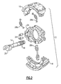
Figure 2 is an exploded view of a cam brake assembly such as that depicted inFigure 1 . -
Figure 3 is a side view of a slack adjuster in an assembled condition. -
Figure 4 is an exploded view of the slack adjuster ofFigure 3 . -
Figure 5 is a cross-sectional view of the slack adjuster ofFigure 3 . -
Figure 6A is a magnified view ofFigure 5 showing a manual adjuster in a non-adjusting position. -
Figure 6B is a magnified view ofFigure 5 showing the manual adjuster in an adjusting position. -
Figure 7 is a figure similar toFigure 3 but shows a cross-section at a connection between an actuator disc and push rod. - As shown in
Figures 1 and2 , abrake actuation system 10 is used to actuate avehicle wheel brake 12 in response to a brake request. In one example, thewheel brake 12 comprises a cam brake with acamshaft 14 that is configured to press a pair ofbrake shoes 16 into engagement with abrake drum 18 configured to rotate with a vehicle wheel. Thecamshaft 14 includes an S-shaped cam 20 at one end that, upon rotation, is configured to pivot thebrake shoes 16 outwardly into engagement with aninner braking surface 22 of thedrum 18. - The
brake shoes 16 are coupled to abrake spider 24 viaanchor pins 26. Thebrake spider 24 is configured to be mounted to an axle housing or non-rotating wheel end component. Areturn spring 28a facilitates returning thebrake shoes 16 to the non-applied position upon completion of a braking request. Shoe retainingsprings 28b couple the brake shoes together adjacent theanchor pins 26. - As shown in
Figure 3 , theactuation system 10 includes a pressure input member, such as abrake air chamber 30 for example, which has an actuatingrod 32 that is coupled to abrake actuation lever 34. Pressure operating on a diaphragm within thebrake chamber 30 in response to a brake request, such as that initiated by depression of a brake foot pedal, forces the actuatingrod 32 outwardly, which in turn rotates theactuation lever 34. Thelever 34 extends in a generally vertical direction and is coupled to thecamshaft 14, which rotates thecam 20 to press thebrake shoes 16 outwardly into engagement with thebrake drum 18 to stop the vehicle. - When the brake pedal is released, air pressure is exhausted from the
brake chamber 30 and a spring or other return mechanism is configured to return the actuatingrod 32 and lever 34 to a retracted, brake-off position. This also causes thebrake shoes 16 to return to a non-applied position. In this non-applied position, there is a clearance space S, i.e. slack, betweenbrake friction linings 36 on thebrake shoes 16 and theengagement surface 22 on thebrake drum 18. Over time, the thickness of thebrake friction linings 36 decreases or wears, which in turn increases the slack. If slack becomes excessive, it may not be possible to provide a sufficient braking force to thedrum 18, i.e. the actuatingrod 32 may not be able to rotate thelever 34 far enough to exert a sufficient braking force against thedrum 18. - To ensure that the
actuation lever 34 is rotated to produce a desired amount of brake force, thelever 34 is coupled to acoupling member 38, which can be adjusted throughout the life of the brake shoes to ensure that thecam 20 is properly positioned in relation to the brake shoes to provide the desired braking force. An automaticslack adjuster mechanism 40 is used to automatically readjust the coupling member as the brake linings wear. - When an automatic
slack adjuster mechanism 40 is installed, a brake chamber stroke measurement is set, which corresponds to the desired or correct shoe-to-drum clearance. As thebrake linings 36 wear, this clearance, i.e. slack, increases and the brakechamber actuating rod 32 must travel farther to apply the brakes. Once this clearance or "slack" is increased beyond a predetermined limit, the slack adjuster is configured to automatically adjust during the return stroke to maintain the correct shoe-to-drum clearance. If the air brake chamber push rod stroke is within acceptable limits during operation, no adjustment occurs. - In the example shown in
Figures 4-6B , thecoupling member 38 comprises aworm gear 42 positioned within ahousing 44. Theworm gear 42 includes a splinedinner opening 46 that is attached to asplined end 48 of the camshaft 14 (Figure 2 ) that is opposite of thecam 20. A first set ofworm teeth 50 are formed about an outer circumference of theworm gear 42. - The
slack adjuster mechanism 40 includes aworm shaft 52, which has a second set ofworm teeth 54 that are directly engaged with the first set ofworm teeth 50. Theworm shaft 52 is positioned within thehousing 44 such that theworm shaft 52 is extending in a generally horizontal direction relative to thelever 34. In other words, theworm shaft 52 extends transversely relative to thelever 34, as opposed to extending generally parallel to thelever 34. - The
slack adjuster mechanism 40 further includes anactuator disc 60, acontrol disc 62, abushing 64, and anend cover 66. Thehousing 44 includes a blind-bore or blind-hole 70, i.e. a hole having only one open end, which receives these components, as well as theworm shaft 52, as a sub-assembly. The blind-hole 70 is solely formed by a machining operation from one side of thehousing 44 such that thehole 70 does not extend entirely through thehousing 44 as shown inFigure 5 . This provides a fully enclosed end within the housing itself, and eliminates any cap, plug, or cover that is typically required to seal off an open end to protect the internal components from contaminants. - The
worm shaft 52 includes agear portion 72 that includes the second set ofworm teeth 54, a reducedneck portion 74 that supports thebushing 64, and asplined shaft portion 76 that is coupled to thecontrol disc 62 via a mating splined bore 78 formed within thecontrol disc 62. As shown inFigure 6A , one end face of thebushing 64 engages an end face on the worm shaft between theneck portion 74 andgear portion 72. An opposite end face of thebushing 64 engages ashoulder 80 formed within thehousing 44. Thebushing 64 includes abore 82 that rotatably supports theworm shaft 52 at theneck portion 74. - The
control disc 62 includes afirst end face 84 that faces thebushing 64 and asecond end face 86 that faces theend cover 66. Thecontrol disc 62 includes a plurality ofcontrol teeth 88 on thesecond end face 86. A resilient member 90, such as a coil spring for example, has one spring end in engagement with thefirst end face 84 and a second spring end in engagement with thebushing 64. The resilient member 90 loads thecontrol teeth 88 into engagement withactuator teeth 92 on theactuator disc 60. As such, theactuator 60 andcontrol 62 discs are always in contact with each other. In one rotational direction, i.e. a brake apply direction, theactuator teeth 92 skip past thecontrol teeth 88. In an opposite rotational direction, i.e. a brake return direction, theactuator teeth 92 drive against thecontrol teeth 88, causing thecontrol disc 62 to rotate, and hence theworm shaft 52 to rotate. - The
actuator teeth 92 are formed on afirst end 94 of theactuator disc 60, which faces thecontrol disc 62. Asecond end 96 of theactuator disc 60 faces theend cover 66. Theactuator disc 60 has an outer circumference that is close to the diameter of the blind-hole 70 such that theactuator disc 60 sits within the blind-hole in a light press-fit or slightly loose fit. Asnap ring 98 is installed within the blind-hole to hold theactuator disc 60 at a desired axial location. - The
end cover 66 includes ahub portion 100 at one end and aknob portion 102 that extends outwardly of thehousing 44 at an opposite end. Thehub portion 100 includes anouter surface 104 that has a slightly smaller diameter than an inner diameter of a center bore 106 of theactuator disc 60. This allows thehub portion 100 to be inserted into the center bore 106 without contacting theactuator disc 60. Thehub portion 100 includes a blind-bore 108 that has a splined innercircumferential surface 110. Anend face 112 of thehub portion 100 abuts against thecontrol disc 62. - A
seal 114 holds theend cover 66 within thebore 70. An optional snap ring 116 (Figure 4 ) could also be used to provide additional securement for theend cover 66. Theseal 114 abuts against aflange portion 118 of theend cover 66. Theflange portion 118 is generally centrally located on the end cover and is defined by a diameter that is larger than thehub 100 andknob 102 portions. Anouter surface 120 of theseal 114 sealing engages asurface 122 that defines thebore 70. - The
knob portion 102 extends outwardly of thehousing 44. In one example, theknob portion 102 is configured to provide a grasping surface and/or atool engagement surface 124 to provide a manual adjustment feature. This will be discussed in greater detail below. - The housing 44 (
Figures 3-4 ) includes aclevis attachment 130 that is coupled to thepush rod 32 of theair chamber 30 in a known manner. A push rod 132 (Figure 4 ) has afirst end 134 coupled to theclevis attachment 130 in a known manner and asecond end 136 that is in engagement with theactuator disc 60 as shown inFigure 7 . In the example shown, theactuator disc 60 includes a pair of grooves 128 (Figure 4 ) formed in an outer surface on one side of theactuator disc 60. A mating portion of thepush rod 132, adjacent thesecond end 136, cooperates with thesegrooves 128 such that thepush rod 132 andactuator disc 60 are always in contact. Thehousing 44 includes an opening on an upper surface that extends into the blind bore to allow thepush rod 132 to engage theactuator disc 60. - The
slack adjuster mechanism 40 operates in the following manner. A brake request is initiated, for example, by pressing a brake pedal. In the brake apply direction, if there is significant lining wear, i.e. lining wear has exceed a predetermined limit, thepush rod 132 is lifted and rotates theactuator disc 60 such that theactuator teeth 92 skip past thecontrol teeth 88 at least one increment, i.e. at least one tooth increment. The adjustment is made on the brake return stroke as theactuator teeth 92 andcontrol teeth 88 are in driving engagement upon opposite rotation, i.e. theactuator 60 andcontrol 62 discs are locked together on the return stroke. This causes theworm shaft 52 to provide incremental adjustment by rotating theworm gear 42, which in turn rotates thecamshaft 14 to adjust the position of thecam 20. - The
slack adjustment mechanism 40 can also be manually adjusted as needed. In a normal, non-adjustment position (Figure 6A ), theseal 114 holds theend cover 66 in place so that the end cover cannot fall out of thehole 70. The splined innercircumferential surface 110 of thebore 108 is axially spaced from thesplined shaft portion 76 of theworm shaft 52. In this position theend cover 66 can rotate freely within thehole 70. - To manually adjust the worm gear, the
end cover 66 is pressed axially inward in a direction toward theworm shaft 52. This movement results in two simultaneous actions. First, thecontrol disc 62 is disengaged from theactuator disc 60. Second, the splined innercircumferential surface 110 of theend cover 66 is slid into engagement with thesplined shaft portion 76 of theworm shaft 52, as shown inFigure 6B . Rotation of theend cover 66 in this position results in rotation of theworm shaft 52 to adjust slack by rotating theworm gear 42 andcamshaft 14. To rotate theend cover 66, theknob portion 102 is rotated by using a tool, for example. - This manual adjustment configuration is advantageous for several reasons. The
end cover 66 serves to seal the open end of the blind-hole 70 to prevent contaminants from adversely affecting the internal components. Also, a single tool can be used to provide the adjustment. Finally, the end cover does not interface with other components during non-manual adjustment operations. As such, the torque required to adjust the slack is low. Also, there is no wear or damage to adjuster components during manual adjustment because the end cover has disengaged the automatic adjustment system, i.e. thecontrol disc 62 is disengaged from theactuator disc 60. - Another advantage with the subject
slack adjuster mechanism 40 is provided by the blind-hole 70. By assembling the internal slack adjuster components as a sub-assembly that is inserted into the blind-hole 70, overall packaging size is reduced. The compact sub-assembly of internal components, i.e. actuatordisc 60,control disc 62, spring 90,bushing 64, and endcover 66, allow for a veryshort worm shaft 52 and anarrower housing 44. Further, by using a blind-hole as opposed to having a central hole open at both ends, a potential leak path is eliminated. This is critical due to the location of the slack adjuster in relation to the vehicle tires which spray water and road debris onto the slack adjuster. Finally, the blind-hole configuration offers a design where all machining can be accomplished from one direction. All the internal components are loaded in the same direction, which simplifies assembly and shortens the time for manufacturing purposes. Application serial number13,422253, filed March 16, 2012 - The cam operated brake is shown merely as an example, it should be understood that other brake configurations could also be used with the subject slack adjuster. Further, although a preferred embodiment of this invention has been disclosed, a worker of ordinary skill in this art would recognize that certain modifications would come within the scope of this invention. For that reason, the following claims should be studied to determine the true scope and content of this invention.
Claims (15)
- A slack adjuster comprising:a worm shaft configured to drive a worm gear adapted to be coupled to a camshaft;an adjustment assembly receiving slack adjustment input from a push rod, said adjustment assembly configured to automatically rotate said worm shaft when brake slack exceeds a predetermined limit; andmanual adjuster moveable between a non-adjustment position where said manual adjuster is de-coupled from said worm shaft and a manual adjustment position where said manual adjuster is coupled to said worm shaft such that a position of said worm shaft can be manually adjusted.
- The slack adjuster according to claim 1 wherein said manual adjuster is moveable along an axial path between said non-adjustment position and said manual adjustment position.
- The slack adjuster according to claim 1 wherein said worm shaft and adjustment assembly are mounted within a blind-bore formed within a housing, and wherein said manual adjuster comprises an end cover that is positioned within said blind-bore to cover an open end of said blind-bore.
- The slack adjuster according to claim 3 wherein said end cover comprises a hub portion facing said worm shaft and an extension portion that extends outwardly of a housing that encloses said worm shaft, and wherein said hub portion includes an internal bore having a splined surface configured to be coupled to a splined end of said worm shaft when said end cover is moved into said manual adjustment position.
- The slack adjuster according to claim 3 wherein said adjustment assembly comprises a control disc that is fixed for rotation with said worm shaft and an actuator disc that is coupled to the push rod.
- The slack adjuster according to claim 5 wherein said control disc includes a plurality of control teeth and said actuator disc includes a plurality of actuator teeth that are in engagement with said control teeth, and wherein during a brake apply stroke the push rod rotates said actuator disc such that said actuator teeth skip over said control teeth when slack exceeds said predetermined limit, and wherein slack adjustment is automatically provided on a brake return stroke as said actuator teeth drive said control teeth causing said worm shaft to rotate.
- The slack adjuster according to claim 6 including a resilient member that biases said control teeth and said actuator teeth into engagement with each other.
- The slack adjuster according to claim 7 wherein said end cover is moveable to said manual adjustment position by disengaging said control teeth from said actuator teeth by overcoming a biasing force of said resilient member, preferably wherein coupling of said end cover to said worm shaft and disengagement of said control and actuator discs occurs simultaneously.
- The slack adjuster according to claim 3 wherein said end cover is freely rotatable within said bore when in said non-adjustment position, preferably the slack adjuster includes a seal in sealing engagement with said end cover and a surface of said bore, said seal being configured to retain said end cover within said bore.
- The slack adjuster according to claim 1 wherein said manual adjuster disengages automatic slack adjustment provided by said adjustment assembly when moving to said manual adjustment position.
- A method of manually adjusting an automatic slack adjuster comprising the steps of:providing a worm shaft configured to drive a worm gear adapted to be coupled to a camshaft;moving a manual adjuster from a non-adjustment position where the manual adjuster is de-coupled from the worm shaft to a manual adjustment position where the manual adjuster is coupled to the worm shaft; andselectively and manually adjusting a position of said worm shaft by rotating the manual adjuster.
- The method according to claim 11 including providing slack adjustment input to an adjustment assembly configured to automatically rotate the worm shaft when brake slack exceeds a predetermined limit during a braking operation, and disengaging automatic slack adjustment provided by the adjustment assembly when moving the manual adjuster to the manual adjustment position, preferably the step of disengaging automatic slack adjustment and the step of coupling the manual adjuster to the worm shaft occur simultaneously.
- The method according to claim 11 wherein the manual adjuster comprises an end cover, and including installing the worm shaft, adjustment assembly, and end cover within a blind-bore formed within a housing.
- The method according to claim 13 wherein the adjustment assembly comprises a control disc and an actuator disc, and including the steps of
fixing the control disc for rotation with the worm shaft,
coupling the actuator disc to a push rod that receives slack adjustment input, and
resiliently biasing a plurality of control teeth on the control disc into engagement with a plurality of actuator teeth on the actuator disc. - The method according to claim 14 including the steps of
rotating the actuator disc via the push rod during a brake apply such that the actuator teeth skip over the control teeth when slack exceeds a predetermined limit, and
automatically adjusting slack during a brake return stroke as the actuator teeth drive the control teeth causing the worm shaft to rotate, preferably the method includes disengaging the control teeth from the actuator teeth by overcoming a biasing force of the resilient member as the end cover is moved to the manual adjustment position.
Applications Claiming Priority (1)
| Application Number | Priority Date | Filing Date | Title |
|---|---|---|---|
| US13/422,188 US8820490B2 (en) | 2012-03-16 | 2012-03-16 | Manual adjuster for automatic slack adjuster |
Publications (2)
| Publication Number | Publication Date |
|---|---|
| EP2650555A2 true EP2650555A2 (en) | 2013-10-16 |
| EP2650555A3 EP2650555A3 (en) | 2016-03-30 |
Family
ID=47631324
Family Applications (1)
| Application Number | Title | Priority Date | Filing Date |
|---|---|---|---|
| EP13152807.7A Withdrawn EP2650555A3 (en) | 2012-03-16 | 2013-01-28 | Manual adjuster for automatic slack adjuster |
Country Status (4)
| Country | Link |
|---|---|
| US (1) | US8820490B2 (en) |
| EP (1) | EP2650555A3 (en) |
| CN (1) | CN103307152A (en) |
| BR (1) | BR102013006335B1 (en) |
Families Citing this family (7)
| Publication number | Priority date | Publication date | Assignee | Title |
|---|---|---|---|---|
| US9611909B2 (en) * | 2014-08-21 | 2017-04-04 | Arvinmeritor Technology, Llc | Brake assembly having a camshaft seal assembly |
| WO2018220639A1 (en) * | 2017-05-31 | 2018-12-06 | Madras Engineering Industries Private Limited | An automatic slack adjuster |
| CN107327525B (en) * | 2017-07-19 | 2023-07-21 | 重庆宗申机车工业制造有限公司 | Front disc rear drum CBS braking system and braking stroke distribution structure thereof |
| US12529404B2 (en) * | 2020-08-28 | 2026-01-20 | Hendrickson Usa, L.L.C. | Slack adjuster assembly for drum braking systems |
| EP4502414A3 (en) * | 2020-10-07 | 2025-03-12 | Volvo Truck Corporation | High offset slack adjuster with additional low offset arm to reduce lateral loads |
| CN115013460B (en) * | 2022-07-21 | 2023-06-16 | 临沂高新区鸿图电子有限公司 | Linear travel alarm mechanism with adjustable initial position |
| CN118549519B (en) * | 2024-06-25 | 2025-09-19 | 仓信无损检测设备苏州有限公司 | A rotating eddy current testing device |
Family Cites Families (34)
| Publication number | Priority date | Publication date | Assignee | Title |
|---|---|---|---|---|
| US2922317A (en) | 1953-06-12 | 1960-01-26 | Rockwell Standard Co | Slack adjuster |
| US3154178A (en) | 1962-06-01 | 1964-10-27 | Rockwell Standard Co | Automatic slack adjuster |
| US4380276A (en) * | 1980-07-21 | 1983-04-19 | Kelsey-Hayes Co. | Slack adjuster for vehicle brakes |
| US4384638A (en) * | 1981-01-12 | 1983-05-24 | Aeroquip Corporation | Automatic brake slack adjuster |
| US4926980A (en) * | 1981-06-15 | 1990-05-22 | Rockwell International Corporation | Automatic brake adjusting mechanism |
| US4446949A (en) | 1982-01-13 | 1984-05-08 | Rockwell International Corporation | Connecting rod and piston device for a brake slack adjuster |
| GB2123500B (en) * | 1982-07-15 | 1985-09-25 | Aeroquip Ag | Automatic brake slack adjuster |
| US4478317A (en) | 1983-04-11 | 1984-10-23 | Rockwell International Corporation | Slack adjuster for a disc brake |
| US4478316A (en) | 1983-04-11 | 1984-10-23 | Rockwell International Corporation | Slack adjuster for a disc brake |
| US4499976A (en) | 1983-06-16 | 1985-02-19 | Rockwell International Corporation | Slack adjuster for a disc brake |
| US4596319A (en) * | 1983-11-14 | 1986-06-24 | Cumming James C | Automatic slack adjuster for vehicle brakes |
| US4621714A (en) * | 1985-07-12 | 1986-11-11 | Sloan Valve Company | Vehicle slack adjuster clutch |
| US5350043A (en) * | 1993-03-05 | 1994-09-27 | Crewson Brunner Inc. | Automatic slack adjuster |
| DE19515063C2 (en) | 1995-04-27 | 2002-06-06 | Knorr Bremse Systeme | Disc brake for vehicles, in particular road vehicles |
| GB9823199D0 (en) | 1998-10-24 | 1998-12-16 | Lucas Ind Plc | Vehicle brake having brake de-adjust |
| US6213264B1 (en) | 1996-10-15 | 2001-04-10 | Meritor Heavy Vehicle Systems, L.L.C. | Sealing arrangement for brake camshaft |
| US5992579A (en) | 1997-08-07 | 1999-11-30 | Meritor Heavy Vehicle Systems, Llc | Method and apparatus for detecting an improperly adjusted slack adjuster |
| US6119822A (en) | 1998-11-30 | 2000-09-19 | Meritor Heavy Vehicle Systems, Llc | Drum brake with rack and pinion drive |
| US6481542B2 (en) | 2001-02-19 | 2002-11-19 | Meritor Heavy Vehicle Systems, Llc. | Brake adjuster |
| US20040026193A1 (en) | 2002-08-08 | 2004-02-12 | Philpott Daniel J. | Slack adjuster torque limited manual adjustment |
| US6896106B2 (en) | 2002-10-02 | 2005-05-24 | Arvinmeritor Technology, Llc | Method and assembly for automatic slack adjustment of an electric brake actuator |
| US7931129B2 (en) | 2003-01-31 | 2011-04-26 | Arvinmeritor Technology, Llc | Rapid take up and vibration proof adjuster mechanism |
| US7032722B2 (en) | 2003-07-07 | 2006-04-25 | Arvinmeritor Technology, Llc | Multiple ball screw assembly with differing pitch used to optimize force and displacement of brake actuator |
| US8181752B2 (en) | 2003-08-20 | 2012-05-22 | Arvinmeritor Technology, Llc | Brake overstroke indication system |
| US7124862B2 (en) * | 2003-09-25 | 2006-10-24 | Arvinmeritor Technology, Llc | Brake slack adjuster |
| US20050145449A1 (en) | 2003-12-29 | 2005-07-07 | Jelley Frederick A. | Gain stabilizing self-energized brake mechanism |
| US7055658B2 (en) | 2003-12-29 | 2006-06-06 | Arvinmeritor Technology, Llc | Gain stabilizing self-energized brake mechanism |
| US20060163014A1 (en) * | 2005-01-27 | 2006-07-27 | Crewson Gary E | Automatic slack adjuster with spring release spindle |
| US7246690B2 (en) | 2005-03-08 | 2007-07-24 | Arvinmeritor Technology, Llc | Air disc brake adjuster |
| US20070012529A1 (en) * | 2005-07-18 | 2007-01-18 | Kreidler Kevin L | Automatic slack adjuster |
| US7708122B2 (en) * | 2005-08-23 | 2010-05-04 | Bendix Commercial Vehicle Systems Llc | Automatic slack adjuster |
| GB0608955D0 (en) | 2006-05-05 | 2006-06-14 | Meritor Heavy Vehicle Braking | Disc brake operating mechanism |
| GB0608956D0 (en) | 2006-05-05 | 2006-06-14 | Meritor Heavy Vehicle Braking | Disc brake wear aduster |
| CN101526116B (en) * | 2009-03-24 | 2012-03-07 | 隆中控股集团有限公司 | Automatic adjusting arm of automobile |
-
2012
- 2012-03-16 US US13/422,188 patent/US8820490B2/en active Active
-
2013
- 2013-01-28 EP EP13152807.7A patent/EP2650555A3/en not_active Withdrawn
- 2013-02-19 CN CN2013100536419A patent/CN103307152A/en active Pending
- 2013-03-15 BR BR102013006335-5A patent/BR102013006335B1/en active IP Right Grant
Also Published As
| Publication number | Publication date |
|---|---|
| CN103307152A (en) | 2013-09-18 |
| US8820490B2 (en) | 2014-09-02 |
| BR102013006335A2 (en) | 2015-06-02 |
| EP2650555A3 (en) | 2016-03-30 |
| US20130240307A1 (en) | 2013-09-19 |
| BR102013006335B1 (en) | 2021-12-21 |
Similar Documents
| Publication | Publication Date | Title |
|---|---|---|
| US8820490B2 (en) | Manual adjuster for automatic slack adjuster | |
| US3949840A (en) | Cam brake automatic slack adjusting mechanism | |
| JP6486490B2 (en) | Disc brakes for commercial vehicles | |
| US11173889B2 (en) | Disc brake assembly | |
| CA1183465A (en) | Automatic slack adjuster | |
| CN102112774B (en) | Adjustment device for disk brake | |
| EP2538104B1 (en) | A brake | |
| EP1805431B1 (en) | Automatic slack adjuster for a vehicle drum brake | |
| EP2639474A2 (en) | Adjustment assembly installation into automatic slack adjuster housing | |
| CN110410439B (en) | Actuating mechanism | |
| EP1917451B1 (en) | An automatic brake adjuster for adjusting the slack between the brake lining and brake drum of a vehicular braking system | |
| US10598238B2 (en) | Slack adjuster for a drum brake of a vehicle air braking system | |
| KR100307544B1 (en) | Actuator with automatic adjustment for truck and bus brakes | |
| US7124862B2 (en) | Brake slack adjuster | |
| US20130299287A1 (en) | Vehicle disc brake assembly having a mechanically actuated parking brake | |
| GB1596324A (en) | Pressure medium operable disc brake | |
| HK40000163A (en) | An automatic slack adjuster | |
| HK1105677B (en) | An automatic brake adjuster for adjusting the slack between the brake lining and brake drum of a vehicular braking system | |
| HK1119454B (en) | An automatic brake adjuster for adjusting the slack between the brake lining and brake drum of a vehicular braking system |
Legal Events
| Date | Code | Title | Description |
|---|---|---|---|
| PUAI | Public reference made under article 153(3) epc to a published international application that has entered the european phase |
Free format text: ORIGINAL CODE: 0009012 |
|
| AK | Designated contracting states |
Kind code of ref document: A2 Designated state(s): AL AT BE BG CH CY CZ DE DK EE ES FI FR GB GR HR HU IE IS IT LI LT LU LV MC MK MT NL NO PL PT RO RS SE SI SK SM TR |
|
| AX | Request for extension of the european patent |
Extension state: BA ME |
|
| PUAL | Search report despatched |
Free format text: ORIGINAL CODE: 0009013 |
|
| AK | Designated contracting states |
Kind code of ref document: A3 Designated state(s): AL AT BE BG CH CY CZ DE DK EE ES FI FR GB GR HR HU IE IS IT LI LT LU LV MC MK MT NL NO PL PT RO RS SE SI SK SM TR |
|
| AX | Request for extension of the european patent |
Extension state: BA ME |
|
| RIC1 | Information provided on ipc code assigned before grant |
Ipc: F16D 65/50 20060101AFI20160224BHEP |
|
| STAA | Information on the status of an ep patent application or granted ep patent |
Free format text: STATUS: THE APPLICATION IS DEEMED TO BE WITHDRAWN |
|
| 18D | Application deemed to be withdrawn |
Effective date: 20161001 |