EP2650534A1 - Nacelle roof structure of wind turbine generator - Google Patents
Nacelle roof structure of wind turbine generator Download PDFInfo
- Publication number
- EP2650534A1 EP2650534A1 EP11846474.2A EP11846474A EP2650534A1 EP 2650534 A1 EP2650534 A1 EP 2650534A1 EP 11846474 A EP11846474 A EP 11846474A EP 2650534 A1 EP2650534 A1 EP 2650534A1
- Authority
- EP
- European Patent Office
- Prior art keywords
- nacelle
- roof
- wind turbine
- turbine generator
- plate
- Prior art date
- Legal status (The legal status is an assumption and is not a legal conclusion. Google has not performed a legal analysis and makes no representation as to the accuracy of the status listed.)
- Granted
Links
- 230000008878 coupling Effects 0.000 claims abstract description 52
- 238000010168 coupling process Methods 0.000 claims abstract description 52
- 238000005859 coupling reaction Methods 0.000 claims abstract description 52
- XLYOFNOQVPJJNP-UHFFFAOYSA-N water Substances O XLYOFNOQVPJJNP-UHFFFAOYSA-N 0.000 description 10
- 238000000465 moulding Methods 0.000 description 7
- 229920002430 Fibre-reinforced plastic Polymers 0.000 description 5
- 239000011151 fibre-reinforced plastic Substances 0.000 description 5
- 238000004519 manufacturing process Methods 0.000 description 3
- 230000000694 effects Effects 0.000 description 2
- 238000009434 installation Methods 0.000 description 2
- 238000012423 maintenance Methods 0.000 description 2
- 238000000034 method Methods 0.000 description 2
- 239000012141 concentrate Substances 0.000 description 1
- 238000010586 diagram Methods 0.000 description 1
- 230000008595 infiltration Effects 0.000 description 1
- 238000001764 infiltration Methods 0.000 description 1
- 239000000463 material Substances 0.000 description 1
- 238000009755 vacuum infusion Methods 0.000 description 1
Images


Classifications
-
- F—MECHANICAL ENGINEERING; LIGHTING; HEATING; WEAPONS; BLASTING
- F03—MACHINES OR ENGINES FOR LIQUIDS; WIND, SPRING, OR WEIGHT MOTORS; PRODUCING MECHANICAL POWER OR A REACTIVE PROPULSIVE THRUST, NOT OTHERWISE PROVIDED FOR
- F03D—WIND MOTORS
- F03D80/00—Details, components or accessories not provided for in groups F03D1/00 - F03D17/00
-
- F—MECHANICAL ENGINEERING; LIGHTING; HEATING; WEAPONS; BLASTING
- F05—INDEXING SCHEMES RELATING TO ENGINES OR PUMPS IN VARIOUS SUBCLASSES OF CLASSES F01-F04
- F05B—INDEXING SCHEME RELATING TO WIND, SPRING, WEIGHT, INERTIA OR LIKE MOTORS, TO MACHINES OR ENGINES FOR LIQUIDS COVERED BY SUBCLASSES F03B, F03D AND F03G
- F05B2240/00—Components
- F05B2240/10—Stators
- F05B2240/14—Casings, housings, nacelles, gondels or the like, protecting or supporting assemblies there within
-
- Y—GENERAL TAGGING OF NEW TECHNOLOGICAL DEVELOPMENTS; GENERAL TAGGING OF CROSS-SECTIONAL TECHNOLOGIES SPANNING OVER SEVERAL SECTIONS OF THE IPC; TECHNICAL SUBJECTS COVERED BY FORMER USPC CROSS-REFERENCE ART COLLECTIONS [XRACs] AND DIGESTS
- Y02—TECHNOLOGIES OR APPLICATIONS FOR MITIGATION OR ADAPTATION AGAINST CLIMATE CHANGE
- Y02B—CLIMATE CHANGE MITIGATION TECHNOLOGIES RELATED TO BUILDINGS, e.g. HOUSING, HOUSE APPLIANCES OR RELATED END-USER APPLICATIONS
- Y02B10/00—Integration of renewable energy sources in buildings
- Y02B10/30—Wind power
-
- Y—GENERAL TAGGING OF NEW TECHNOLOGICAL DEVELOPMENTS; GENERAL TAGGING OF CROSS-SECTIONAL TECHNOLOGIES SPANNING OVER SEVERAL SECTIONS OF THE IPC; TECHNICAL SUBJECTS COVERED BY FORMER USPC CROSS-REFERENCE ART COLLECTIONS [XRACs] AND DIGESTS
- Y02—TECHNOLOGIES OR APPLICATIONS FOR MITIGATION OR ADAPTATION AGAINST CLIMATE CHANGE
- Y02E—REDUCTION OF GREENHOUSE GAS [GHG] EMISSIONS, RELATED TO ENERGY GENERATION, TRANSMISSION OR DISTRIBUTION
- Y02E10/00—Energy generation through renewable energy sources
- Y02E10/70—Wind energy
- Y02E10/72—Wind turbines with rotation axis in wind direction
Definitions
- the present invention relates to a nacelle roof structure of a wind turbine generator.
- a wind turbine generator is designed to generate electric power using a generator which is driven as a rotor head equipped with wind turbine blades is rotated by wind power and the rotation is speeded up by a gear box.
- the rotor head is installed on an end portion of a nacelle which, being mounted on a wind turbine tower, is capable of yawing, and is supported in such a way as to be able to rotate around a substantially horizontal transverse rotation axis.
- a nacelle cover adapted to cover the nacelle of the wind turbine generator is generally constructed by connecting plural fiber reinforced plastic (FRF) panels and a connection structure for the panels needs to be designed to be able to prevent infiltration of rainwater from outside the nacelle cover.
- panel connections are generally joined by bolts, but when the nacelle cover is subjected to external forces caused by wind pressure, snow cover, or the like, the panel connections joined by bolts become the weakest part in terms of strength. Therefore, the panel connections need to have a structure free from high material strain.
- a roofing member 3 adapted to cover a top face of a nacelle 2 is configured by integrating roof shingles 3L and 3R which divide the nacelle into two parts -- right and left partsin a width direction and is mounted by being connected with upper end portions of nacelle side-walls 4.
- the nacelle 2 is shaped substantially as a rectangular parallelepiped. When viewed from above, the nacelle 2 is rectangular in planar view and the long edge corresponds to a front-rear direction which coincides with a main-shaft direction while the short edge corresponds to a width direction.
- the roof shingles 3L and 3R are joined by fastening respective flanges 3a by bolt connection as shown in Fig. 6(b) and a joining line L between the roof shingles 3L and 3R extends to a length substantially equal to that of the long edge (main-shaft direction) of the nacelle 2.
- the flanges 3a joining together the roof shingles 3L and 3R are set at such an angle that a joined portion of the roofing member 3 will be slightly higher when fastening is complete.
- the flanges 3a at the joint are not set at right angles to the roof shingles 3L and 3R, but have an angle smaller than 90 degrees ( ⁇ ⁇ 90 degrees) by deviating slightly from a right angle such that the joint bent by fastening will be convex upward with respect to an outer periphery of the nacelle 2.
- the roofing member 3 becomes larger along with the nacelle shape, the dimension from the joining line L to the nacelle side-walls 4 increases and becomes longer, making it necessary to deal with stress concentration more strictly, and it is feared that the flange coupling described above could be broken in the worst case. Furthermore, when the roofing member 3 increases in size, the shape of the roof shingles 3L and 3R equipped with the flanges 3a become larger as well due to the right/left two-block structure. Moreover, since the flanges 3a which protrude also grow in size, it becomes difficult to efficiently perform loading and subsequent transport from a manufacturing plant to an installation site.
- the roofing member 3 which is part of the nacelle cover of the wind turbine generator is structured to be able to be removed and reinstalled easily.
- the roofing member 3 which makes up roof part of the nacelle cover needs to be made removable to take sufficient measures against intrusion of rain water.
- the wall panel connection structure disclosed in PTL 1 is a connection structure for wall panels used in housing and is different from a nacelle roof structure of a wind turbine generator, which uses fiber reinforced plastic panels.
- the present invention has been made in view of the above circumstances and has an object to provide a nacelle roof structure of a wind turbine generator, where the nacelle roof structure, which makes up a nacelle cover, is capable of reducing stress concentration on joints of a roofing member divided into multiple parts to accommodate growing size of a nacelle as well as improving transport efficiency of the roofing member.
- the present invention provides a nacelle roof structure of a wind turbine generator, with a top face of a nacelle being covered with a plate-type roofing member, wherein: the roofing member has a joining structure in which roof shingles that divide the roofing member into a plurality of parts in a main-shaft direction are combined and plate couplings provided at opposite ends in the main-shaft direction are fastened together by being laid one on top of another; and two or more of the roof shingles are equal in cut length in the main-shaft direction.
- the roofing member covering the top face of the nacelle has a joining structure in which the roof shingles that divide the roofing member into a plurality of parts in the main-shaft direction are combined and plate couplings provided at opposite ends in the main-shaft direction are fastened together by being laid one on top of the other, and two or more of the roof shingles are equal in cut length in the main-shaft direction. Consequently, the joining structure in which the plate couplings of the roof shingles are fastened together by being laid one on top of another extends in a short-edge (width) direction of the nacelle orthogonal to the main-shaft direction, preventing excessive stress concentration on the joining structure. Also, since two or more roof shingles are equal in cut length in the main-shaft direction, it is possible to reduce manufacturing cost through adoption of vacuum molding or sharing of a molding tool as well as to perform efficient transport by piling up roof shingles of a same size.
- each of the roof shingles includes curved portions located on opposite end sides in a width direction orthogonal to the main-shaft direction and configured to shift direction downward toward roof couplings coupled to nacelle side-walls; and the corrugations are formed up to a neighborhood of roof couplings including the curved portions.
- the corrugations may be made concave with respect to external part of the nacelle. This allows the corrugations to be used as discharge channels, improving water drainage on roof part of the nacelle.
- the roof shingles are laid in an overlapping manner with the plate coupling on a windward side being placed on an upper side.
- a stepped portion is provided to make joined surfaces of the plate couplings higher than a roof level. This will further improve water tightness against rainwater.
- the plate coupling on the windward side extends a leeward-side end portion of the joined surface placed on the upper side further leeward than start position of a stepped area of the underlying plate coupling on a leeward side. This will even further improve water tightness against rainwater.
- the nacelle roof structure of a wind turbine generator according to the present invention reduces stress concentration on a joining structural portion of the roofing member divided into multiple roof shingles and produces marked effects on improving rigidity of the joining structural portion and improving transport efficiency of the roof shingles which make up the roofing member.
- FIGS. 1 and 2 show an exemplary structure of a nacelle to which the nacelle roof structure of a wind turbine generator according to the present invention is applied
- Fig. 3 shows a roof shingle making up a roofing member
- Fig. 4 is a sectional view taken along line A-A in Fig. 2
- Fig. 5 is a sectional view taken along line B-B in Fig. 2 .
- the nacelle roof structure of a wind turbine generator is applied to an external wall member covering a nacelle 20 of the wind turbine generator.
- the nacelle 20 is installed on an upper end portion of a tower and adapted to house equipment such as a gear box and generator installed therein, where the equipment is coupled to a rotor via a main shaft, the rotor being equipped with wind turbine blades.
- a nacelle cover which is an external wall member, is made of fiber reinforced plastic (FRP).
- a top opening in a top face of the nacelle 20 is covered with plate-type roofing member 30.
- the nacelle 20 is shaped substantially as a rectangular parallelepiped.
- the opening formed in the top face is covered by the roofing member 30 which is detachably mounted on upper end portions of nacelle side-walls 21 forming side-walls.
- the upper opening is used to carry in and out the equipment installed in the nacelle, with the roofing member 30 removed.
- the nacelle 20 is substantially rectangular in planar view, and a front-rear direction which coincides with a main-shaft direction corresponds to the long edge while a width direction corresponds to the short edge.
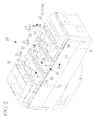
- the roofing member 30 adopts a joining structure in which roof shingles 31 which divide the roofing member 30 into multiple parts in the main-shaft direction are combined using a joining structural portion 32 and plate couplings 32a and 32b of the roof shingles 31 provided at opposite ends in the main-shaft direction are fastened together by being laid one on top of the other.
- the roofing member 30 is mounted so as to cover the upper opening excluding the foremost roof area in which an exhaust port 40 is installed.
- the roofing member 30 is divided in the main-shaft direction into four overlapping roof shingles 31 which, are integrated by the joining structural portions 32.
- the roof shingles 31 will be denoted by 31a, 31b, 31c, and 31d starting from the nacelle's front side on which the rotor (not shown) is mounted.
- roof shingles 31 Two or more of the roof shingles 31 are equal in cut length in the main-shaft direction.
- three roof shingles 31a, 31b, and 31c are substantially identical in shape and equal in cut length in the main-shaft direction.
- the roof shingle 31 shown in Fig. 3 provides a basic shape of the roof shingles 31a, 31b, and 31c, which are plate-type members identical in length and shape both in the front-rear direction and width direction. That is, the roof shingles 31a, 31b, and 31c can be formed using molding tools created by individually modifying a molding tool of the same basic shape according to the layout and number of hatch locations 33.
- the roof shingle 31 described above has corrugations 34 formed substantially in parallel to the plate couplings 32a and 32b.
- the corrugations 34 are convex or concave portions formed on the plate-type roof shingle 31 and are capable of increasing rigidity of the plate-type member especially against an input load tending to fold the roof shingle 31 in the width direction.
- the corrugations 34 can also increase rigidity of the joining structural portion 32 located near the corrugations 34 and used to lay the roof shingles 31 in an overlapping manner.
- the concavo-convexity of the corrugations 34 has a sectional shape such as a substantially trapezoidal shape with four vertices, i.e., a sectional shape made up of a combination of straight lines with vertices rather than curved surfaces such as arcs.
- the corrugations 34 are placed close to the plate couplings 32a and 32b, i.e., within a distance smaller than the width of the corrugations 34.
- the concave sectional shape of the corrugations 34 described above allows the concave portions to be utilized effectively as discharge channels as well. That is, since the corrugations 34 with the concave sectional shape also function as discharge channels which extend in the width direction of the roof shingle 31 in parallel to the joining structural portion 32, on roof part of the nacelle 20, water drainage on the top face (external surface) of the roofing member 30 is improved and an amount of rainwater reaching the joining structural portion 32 is minimized.
- the sectional shape of the corrugations 34 when, for example, vacuum molding (vacuum infusion process) is adopted, desirably the angle ⁇ shown in Fig. 4(a) is set to 30 degrees or below.
- the roof shingles 31 are laid in an overlapping manner with the plate coupling 32a or 32b on the windward side being placed on top of the other. That is, as shown in Fig. 4 , since the roof shingle 31a, which is on the front side of the nacelle, is always located on the windward side due to yawing, desirably the plate coupling 32a provided on the rear end side of the roof shingle 31a is laid on top of the plate coupling 32a provided on the front end side of the roof shingle 31b.
- the roofing member 30 of the nacelle 20 is structured such that when flowing from front part to rear part of the nacelle, rainwater under the influence of wind flows on a top face of the plate coupling 32a placed on the upper side, making it difficult for rainwater to enter the nacelle through joined surfaces of the joining structural portion 32. This improves the water tightness of the joining structural portion 32 of the roof panel member 30 against rainwater.
- stepped portions 35a and 35b are provided to make the plate couplings 32a and 32b slightly higher than a roof level in central part such that the joined surfaces of the plate couplings 32a and 32b laid one on top of the other will be higher than the roof level of the roofing member 30.
- the stepped portions 35a and 35b since the plate couplings 32a and 32b are laid one on top of the other with the one on the windward side being placed on the upper side, the stepped portion 35a provided on the rear end side of the roof shingle 31a on the windward side is slightly larger in step height.
- the windward-side plate coupling 32a laid on the upper side extends a leeward-side end portion of its joined surface further leeward than start position of an area containing the stepped portion 35b of the underlying plate coupling 32a on the leeward side. That is, desirably the (leeward-side) end portion closer to the rear side of the nacelle of the windward-side plate coupling 32a either coincides in position with the start position of the stepped portion 35b formed on the leeward-side plate coupling 32b or extends further rearward (leeward) on the nacelle than the start position.
- the leeward-side end portion of the plate coupling 32a has an extended portion with a length of S (S ⁇ 0) in a leeward direction from the start position of the stepped portion 35b.
- S S ⁇ 0
- the plate coupling 32a is extended in this way, even if rainwater flows rearward on the roofing member 30 under the influence of wind, the rainwater drops on a sloped surface of the stepped portion 35b a step lower than the joined surface. This further improves the water tightness of the joining structural portion 32 of the roof panel member 30 against rainwater.
- the roofing member 30 covering the top face of the nacelle 20 has the joining structural portion 32 in which the roof shingles 31 that divide the roofing member 30 into multiple parts in the main-shaft direction are combined and the plate couplings 32a and 32b provided at opposite ends in the main-shaft direction are fastened together by being laid one on top of the other. Furthermore, two or more of the roof shingles 31 are equal in cut length in the main-shaft direction.
- the joining structural portion 32 in which the plate couplings 32a and 32b of the roof shingles 31 are fastened together by being laid one on top of the other extends in the short-edge (width) direction of the nacelle 20 orthogonal to the main-shaft direction, reducing the length of the joining structural portion 32 and thereby preventing excessive stress concentration on the joining structural portion 32. Furthermore, since two or more of the roof shingles 31 are equal in cut length in the main-shaft direction, the flangeless structure enables adoption of vacuum molding, manufacturing cost can be reduced through sharing of a basic molding tool, and transport can be performed efficiently by piling up roof shingles 31 of the same size.
- each of the corrugations 34 described above is provided by extending from the central part of the roof continuously to near a lower end portion of curved portions (R portions) 36 formed on opposite end sides of the roof shingle 31 in the width direction.
- the curved portions 36 are configured to shift direction downward toward roof couplings 37 coupled to the nacelle side-walls 21.
- the roof panel 31 provided with the curved portions 36 configured as described above has a substantially channel-shaped sectional shape in the width direction.
- the corrugations 34 are not only formed in the central portion of the roof shingle 31, but also formed continuously up to near the lower end portions of the curved portions 36 and near the roof couplings 37 located at opposite lower end portions of the roof shingle 31 in the width direction.
- the corrugations 34 configured as described above can not only further improve rigidity of the roof shingles 31 and the joining structural portion 32, but also simplify the shape (structure) of the coupling connection between the roof couplings 37 and nacelle side-walls 21 by making roof side-walls without corrugations planar near the lower end portions of the curved portions 36.
- the hatch location 33 provided in the roof shingle 31 if a hatch mounting flange 33b of an opening 33a provided in the roof shingle 31 is set slightly higher than the roof level, for example, as shown in Fig. 5 , it is possible to prevent rainwater from entering through the hatch location 33.
- the present embodiment described above can reduce stress concentration on the joining structural portion 32 of the roofing member 30 divided into multiple roof shingles 31 and improve the rigidity of the joining structural portion 32 as well as the transport efficiency of the roof shingles 31 which are roofing components .
- the joining structural portions 32 of the roofing member 30 described as having a block structure although the roof shingles 31 are removed during a maintenance operation or the like, since appropriate measures are taken against rainwater intrusion in the joining structural portions 32, the nacelle roof structure of a wind turbine generator has a combination of proper strength, transportation efficiency, and water tightness.
Landscapes
- Engineering & Computer Science (AREA)
- Life Sciences & Earth Sciences (AREA)
- Sustainable Development (AREA)
- Sustainable Energy (AREA)
- Chemical & Material Sciences (AREA)
- Combustion & Propulsion (AREA)
- Mechanical Engineering (AREA)
- General Engineering & Computer Science (AREA)
- Wind Motors (AREA)
- Roof Covering Using Slabs Or Stiff Sheets (AREA)
Abstract
Description
- The present invention relates to a nacelle roof structure of a wind turbine generator.
- A wind turbine generator is designed to generate electric power using a generator which is driven as a rotor head equipped with wind turbine blades is rotated by wind power and the rotation is speeded up by a gear box. The rotor head is installed on an end portion of a nacelle which, being mounted on a wind turbine tower, is capable of yawing, and is supported in such a way as to be able to rotate around a substantially horizontal transverse rotation axis.
- A nacelle cover adapted to cover the nacelle of the wind turbine generator is generally constructed by connecting plural fiber reinforced plastic (FRF) panels and a connection structure for the panels needs to be designed to be able to prevent infiltration of rainwater from outside the nacelle cover.
Also, panel connections are generally joined by bolts, but when the nacelle cover is subjected to external forces caused by wind pressure, snow cover, or the like, the panel connections joined by bolts become the weakest part in terms of strength. Therefore, the panel connections need to have a structure free from high material strain. - In a conventional nacelle roof structure shown in
Fig. 6 , aroofing member 3 adapted to cover a top face of a nacelle 2 is configured by integratingroof shingles walls 4. Generally, the nacelle 2 is shaped substantially as a rectangular parallelepiped. When viewed from above, the nacelle 2 is rectangular in planar view and the long edge corresponds to a front-rear direction which coincides with a main-shaft direction while the short edge corresponds to a width direction. - The
roof shingles respective flanges 3a by bolt connection as shown inFig. 6(b) and a joining line L between theroof shingles
In this case, theflanges 3a joining together theroof shingles roofing member 3 will be slightly higher when fastening is complete. That is, theflanges 3a at the joint are not set at right angles to theroof shingles - Also, regarding typical structures for wall panel connections, for example, a technique disclosed in PTL 1 (Japanese Unexamined Patent Application, Publication No.
Hei 7-62758 -
- {PTL 1}
Japanese Unexamined Patent Application, Publication No.Hei 7-62758 - Recently, wind turbine generators have been growing in size along with increases in output power, and naturally the shape of the nacelle 2 has been becoming larger. Consequently, the length of the joining line L of the
roof shingles roofing member 3 is increased in the main-shaft direction (front-rear direction cf the nacelle), and furthermore the length from the joining line L to the nacelle side-walls 4 is increased as well.
On the other hand, since no support member is connected to theroofing member 3 except the nacelle side-walls 4, stresses will concentrate on a bolt-connected flange coupling under the load of snow cover or the like. - When the
roofing member 3 becomes larger along with the nacelle shape, the dimension from the joining line L to the nacelle side-walls 4 increases and becomes longer, making it necessary to deal with stress concentration more strictly, and it is feared that the flange coupling described above could be broken in the worst case.
Furthermore, when theroofing member 3 increases in size, the shape of theroof shingles flanges 3a become larger as well due to the right/left two-block structure. Moreover, since theflanges 3a which protrude also grow in size, it becomes difficult to efficiently perform loading and subsequent transport from a manufacturing plant to an installation site. - Also, for example, during maintenance after installation of the wind turbine generator, it becomes necessary to perform the operation of carrying large equipment (including a gear box and generator) installed inside the nacelle cover out of the nacelle cover in a high-elevation, high-wind environment. For that, it is necessary that the
roofing member 3 which is part of the nacelle cover of the wind turbine generator is structured to be able to be removed and reinstalled easily. In particular, theroofing member 3 which makes up roof part of the nacelle cover needs to be made removable to take sufficient measures against intrusion of rain water. - On the other hand, the wall panel connection structure disclosed in PTL 1 is a connection structure for wall panels used in housing and is different from a nacelle roof structure of a wind turbine generator, which uses fiber reinforced plastic panels.
The present invention has been made in view of the above circumstances and has an object to provide a nacelle roof structure of a wind turbine generator, where the nacelle roof structure, which makes up a nacelle cover, is capable of reducing stress concentration on joints of a roofing member divided into multiple parts to accommodate growing size of a nacelle as well as improving transport efficiency of the roofing member. - To solve the above problem, the present invention provides the following solutions.
The present invention provides a nacelle roof structure of a wind turbine generator, with a top face of a nacelle being covered with a plate-type roofing member, wherein: the roofing member has a joining structure in which roof shingles that divide the roofing member into a plurality of parts in a main-shaft direction are combined and plate couplings provided at opposite ends in the main-shaft direction are fastened together by being laid one on top of another; and two or more of the roof shingles are equal in cut length in the main-shaft direction. - With the nacelle roof structure of a wind turbine generator, the roofing member covering the top face of the nacelle has a joining structure in which the roof shingles that divide the roofing member into a plurality of parts in the main-shaft direction are combined and plate couplings provided at opposite ends in the main-shaft direction are fastened together by being laid one on top of the other, and two or more of the roof shingles are equal in cut length in the main-shaft direction. Consequently, the joining structure in which the plate couplings of the roof shingles are fastened together by being laid one on top of another extends in a short-edge (width) direction of the nacelle orthogonal to the main-shaft direction, preventing excessive stress concentration on the joining structure. Also, since two or more roof shingles are equal in cut length in the main-shaft direction, it is possible to reduce manufacturing cost through adoption of vacuum molding or sharing of a molding tool as well as to perform efficient transport by piling up roof shingles of a same size.
- In the invention described above, preferably corrugations substantially parallel to the plate couplings are formed on the roof shingles in a neighborhood of the plate couplings. This increases rigidity of the joining structure in which the roof shingles are laid in an overlapping manner.
In this case, preferably each of the roof shingles includes curved portions located on opposite end sides in a width direction orthogonal to the main-shaft direction and configured to shift direction downward toward roof couplings coupled to nacelle side-walls; and the corrugations are formed up to a neighborhood of roof couplings including the curved portions. This further increases rigidity and simplifies coupling connection with the nacelle side-walls by making roof side-walls without corrugations planar.
Also, the corrugations may be made concave with respect to external part of the nacelle. This allows the corrugations to be used as discharge channels, improving water drainage on roof part of the nacelle. - In the invention described above, preferably the roof shingles are laid in an overlapping manner with the plate coupling on a windward side being placed on an upper side. This will improve water tightness against rainwater at joints of roof shingle members.
In this case, preferably a stepped portion is provided to make joined surfaces of the plate couplings higher than a roof level. This will further improve water tightness against rainwater.
Also, preferably the plate coupling on the windward side extends a leeward-side end portion of the joined surface placed on the upper side further leeward than start position of a stepped area of the underlying plate coupling on a leeward side. This will even further improve water tightness against rainwater. - Even if the roofing member increases in size to accommodate the growing size of the nacelle, the nacelle roof structure of a wind turbine generator according to the present invention reduces stress concentration on a joining structural portion of the roofing member divided into multiple roof shingles and produces marked effects on improving rigidity of the joining structural portion and improving transport efficiency of the roof shingles which make up the roofing member.
-
- {
Fig. 1 }
Fig. 1 is an external side view of a nacelle equipped with a nacelle roof structure of a wind turbine generator according to an embodiment of the present invention. - {
Fig. 2 }
Fig. 2 is an external perspective view of the nacelle shown inFig. 1 . - {
Fig. 3 }
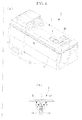
Fig. 3 is a perspective view showing an example of a roof shingle making up part of a roofing member in the nacelle roof structure shown inFigs. 1 and2 . - {
Fig. 4 }
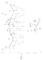
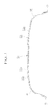
Fig. 4(a) is a sectional view taken along line A-A inFig. 2 , showing a joining structure and corrugations of roof shingles andFig. 4(b) is an enlarged sectional view showing a joining structural portion in which plate couplings are laid one on top of another. - {
Fig. 5 }
Fig. 5 is a sectional view taken along line B-B inFig. 2 . - {
Fig. 6 }
Figs. 6 are diagrams showing an example of a conventional nacelle roof structure of a wind turbine generator, whereFig. 6(a) is an external perspective view of a nacelle andFig. 6(b) is a sectional view showing a joining structure of roof shingles. - A nacelle roof structure of a wind turbine generator according to an embodiment of the present invention will be described below with reference to the drawings.
Figs. 1 and2 show an exemplary structure of a nacelle to which the nacelle roof structure of a wind turbine generator according to the present invention is applied,Fig. 3 shows a roof shingle making up a roofing member,Fig. 4 is a sectional view taken along line A-A inFig. 2 , andFig. 5 is a sectional view taken along line B-B inFig. 2 .
In the embodiments described below, the nacelle roof structure of a wind turbine generator is applied to an external wall member covering anacelle 20 of the wind turbine generator. Thenacelle 20 is installed on an upper end portion of a tower and adapted to house equipment such as a gear box and generator installed therein, where the equipment is coupled to a rotor via a main shaft, the rotor being equipped with wind turbine blades. A nacelle cover, which is an external wall member, is made of fiber reinforced plastic (FRP). - In the nacelle roof structure described below, a top opening in a top face of the
nacelle 20 is covered with plate-type roofing member 30. Thenacelle 20 is shaped substantially as a rectangular parallelepiped. The opening formed in the top face is covered by theroofing member 30 which is detachably mounted on upper end portions of nacelle side-walls 21 forming side-walls. The upper opening is used to carry in and out the equipment installed in the nacelle, with theroofing member 30 removed.
Also, when viewed from above, thenacelle 20 is substantially rectangular in planar view, and a front-rear direction which coincides with a main-shaft direction corresponds to the long edge while a width direction corresponds to the short edge. - The
roofing member 30 according to the present embodiment adopts a joining structure in whichroof shingles 31 which divide theroofing member 30 into multiple parts in the main-shaft direction are combined using a joiningstructural portion 32 andplate couplings roof shingles 31 provided at opposite ends in the main-shaft direction are fastened together by being laid one on top of the other. In the illustrated configuration example, theroofing member 30 is mounted so as to cover the upper opening excluding the foremost roof area in which anexhaust port 40 is installed. In this case, theroofing member 30 is divided in the main-shaft direction into four overlappingroof shingles 31 which, are integrated by the joiningstructural portions 32. Hereinafter, when it is necessary to distinguish among the fourroof shingles 31 resulting from the division, theroof shingles 31 will be denoted by 31a, 31b, 31c, and 31d starting from the nacelle's front side on which the rotor (not shown) is mounted. - Two or more of the
roof shingles 31 are equal in cut length in the main-shaft direction. In the illustrated example, threeroof shingles
Theroof shingle 31 shown inFig. 3 provides a basic shape of theroof shingles roof shingles hatch locations 33. - also, near the
plate couplings structural portion 32, theroof shingle 31 described above has corrugations 34 formed substantially in parallel to theplate couplings corrugations 34 are convex or concave portions formed on the plate-type roof shingle 31 and are capable of increasing rigidity of the plate-type member especially against an input load tending to fold theroof shingle 31 in the width direction. Thus, thecorrugations 34 can also increase rigidity of the joiningstructural portion 32 located near thecorrugations 34 and used to lay theroof shingles 31 in an overlapping manner. In this case, preferably the concavo-convexity of thecorrugations 34 has a sectional shape such as a substantially trapezoidal shape with four vertices, i.e., a sectional shape made up of a combination of straight lines with vertices rather than curved surfaces such as arcs. Also, preferably thecorrugations 34 are placed close to theplate couplings corrugations 34. - Also, the concave sectional shape of the
corrugations 34 described above allows the concave portions to be utilized effectively as discharge channels as well. That is, since thecorrugations 34 with the concave sectional shape also function as discharge channels which extend in the width direction of theroof shingle 31 in parallel to the joiningstructural portion 32, on roof part of thenacelle 20, water drainage on the top face (external surface) of theroofing member 30 is improved and an amount of rainwater reaching the joiningstructural portion 32 is minimized.
Regarding the sectional shape of thecorrugations 34, when, for example, vacuum molding (vacuum infusion process) is adopted, desirably the angle β shown inFig. 4(a) is set to 30 degrees or below. - In the joining
structural portion 32 of theroofing member 30 described above, preferably theroof shingles 31 are laid in an overlapping manner with theplate coupling Fig. 4 , since theroof shingle 31a, which is on the front side of the nacelle, is always located on the windward side due to yawing, desirably theplate coupling 32a provided on the rear end side of theroof shingle 31a is laid on top of theplate coupling 32a provided on the front end side of theroof shingle 31b.
Consequently, theroofing member 30 of thenacelle 20 is structured such that when flowing from front part to rear part of the nacelle, rainwater under the influence of wind flows on a top face of theplate coupling 32a placed on the upper side, making it difficult for rainwater to enter the nacelle through joined surfaces of the joiningstructural portion 32. This improves the water tightness of the joiningstructural portion 32 of theroof panel member 30 against rainwater. - In this case, desirably stepped
portions plate couplings plate couplings roofing member 30. Of the steppedportions plate couplings portion 35a provided on the rear end side of theroof shingle 31a on the windward side is slightly larger in step height.
In this way, when the steppedportions structural portion 32 of theplate couplings structural portion 32 of theroof panel member 30 against rainwater. - Furthermore, regarding the joining
structural portion 32 in which theplate couplings side plate coupling 32a laid on the upper side extends a leeward-side end portion of its joined surface further leeward than start position of an area containing the steppedportion 35b of theunderlying plate coupling 32a on the leeward side. That is, desirably the (leeward-side) end portion closer to the rear side of the nacelle of the windward-side plate coupling 32a either coincides in position with the start position of the steppedportion 35b formed on the leeward-side plate coupling 32b or extends further rearward (leeward) on the nacelle than the start position. To describe specifically with reference toFig. 4 (b) , desirably the leeward-side end portion of theplate coupling 32a has an extended portion with a length of S (S ≥ 0) in a leeward direction from the start position of the steppedportion 35b.
When theplate coupling 32a is extended in this way, even if rainwater flows rearward on theroofing member 30 under the influence of wind, the rainwater drops on a sloped surface of the steppedportion 35b a step lower than the joined surface. This further improves the water tightness of the joiningstructural portion 32 of theroof panel member 30 against rainwater. - In the nacelle roof structure according to the present embodiment configured as described above, the
roofing member 30 covering the top face of thenacelle 20 has the joiningstructural portion 32 in which theroof shingles 31 that divide theroofing member 30 into multiple parts in the main-shaft direction are combined and theplate couplings roof shingles 31 are equal in cut length in the main-shaft direction.
Consequently, the joiningstructural portion 32 in which theplate couplings roof shingles 31 are fastened together by being laid one on top of the other extends in the short-edge (width) direction of thenacelle 20 orthogonal to the main-shaft direction, reducing the length of the joiningstructural portion 32 and thereby preventing excessive stress concentration on the joiningstructural portion 32. Furthermore, since two or more of theroof shingles 31 are equal in cut length in the main-shaft direction, the flangeless structure enables adoption of vacuum molding, manufacturing cost can be reduced through sharing of a basic molding tool, and transport can be performed efficiently by piling uproof shingles 31 of the same size. - To further improve rigidity, desirably each of the
corrugations 34 described above is provided by extending from the central part of the roof continuously to near a lower end portion of curved portions (R portions) 36 formed on opposite end sides of theroof shingle 31 in the width direction. Thecurved portions 36 are configured to shift direction downward towardroof couplings 37 coupled to the nacelle side-walls 21. Theroof panel 31 provided with thecurved portions 36 configured as described above has a substantially channel-shaped sectional shape in the width direction.
Thus, thecorrugations 34 are not only formed in the central portion of theroof shingle 31, but also formed continuously up to near the lower end portions of thecurved portions 36 and near theroof couplings 37 located at opposite lower end portions of theroof shingle 31 in the width direction. - The
corrugations 34 configured as described above can not only further improve rigidity of theroof shingles 31 and the joiningstructural portion 32, but also simplify the shape (structure) of the coupling connection between theroof couplings 37 and nacelle side-walls 21 by making roof side-walls without corrugations planar near the lower end portions of thecurved portions 36.
Regarding thehatch location 33 provided in theroof shingle 31, if ahatch mounting flange 33b of anopening 33a provided in theroof shingle 31 is set slightly higher than the roof level, for example, as shown inFig. 5 , it is possible to prevent rainwater from entering through thehatch location 33. - Even if the
roofing member 30 increases in size to accommodate growth in the size of thenacelle 20, the present embodiment described above, can reduce stress concentration on the joiningstructural portion 32 of theroofing member 30 divided intomultiple roof shingles 31 and improve the rigidity of the joiningstructural portion 32 as well as the transport efficiency of theroof shingles 31 which are roofing components .
Regarding the joiningstructural portions 32 of theroofing member 30 described as having a block structure, although theroof shingles 31 are removed during a maintenance operation or the like, since appropriate measures are taken against rainwater intrusion in the joiningstructural portions 32, the nacelle roof structure of a wind turbine generator has a combination of proper strength, transportation efficiency, and water tightness. - An embodiment of the present invention has been described in detail above with reference to the accompanying drawings, specific configuration of the present invention is not limited to the embodiment described above and, for example, design changes may be made as appropriate without departing from the spirit and scope of the invention.
-
- 20
- Nacelle
- 21
- Side wall panel
- 30
- Roofing member
- 31, 31a to 31d
- Roof shingle
- 32
- Joining structural portion
- 32a, 32b
- Plate coupling
- 33
- Hatch opening
- 34
- Corrugations
- 35a, 35b
- Stepped portion
- 36
- Curved portion (R portion)
- 37
- Roof coupling
- 40
- Exhaust port
Claims (7)
- A nacelle roof structure of a wind turbine generator, with a top face of a nacelle being covered with a plate-type roofing member, wherein:the roofing member has a joining structure in which roof shingles that divide the roofing member into a plurality of parts in a main-shaft direction are combined and plate couplings provided at opposite ends in the main-shaft direction are fastened together by being laid one on top of another; andtwo or more of the roof shingles are equal in cut length in the main-shaft direction.
- The nacelle roof structure of a wind turbine generator according to claim 1, wherein corrugations substantially parallel to the plate couplings are formed on the roof shingles in a neighborhood of the plate couplings.
- The nacelle roof structure of a wind turbine generator according to claim 2, wherein:each of the roof shingles includes curved portions located on opposite end sides in a width direction orthogonal to the main-shaft direction and configured to shift direction downward toward roof couplings coupled to nacelle side-walls; andthe corrugations are formed up to a neighborhood of roof couplings including the curved portions.
- The nacelle roof structure of a wind turbine generator according to claim 2 or 3, wherein the corrugations are made concave with respect to external part of the nacelle.
- The nacelle roof structure of a wind turbine generator, according to any one of claims 1 to 4, wherein the roof shingles are laid in an overlapping manner with the plate coupling on a windward side being placed on an upper side.
- The nacelle roof structure of a wind turbine generator according to claim 5, wherein a stepped portion is provided to make joined surfaces of the plate couplings higher than a roof level.
- The nacelle roof structure of a wind turbine generator according to claim 5 or 6, wherein the plate coupling on the windward side extends a leeward-side end portion of the joined surface placed on the upper side further leeward than start position of a stepped area of the underlying plate coupling on a leeward side.
Applications Claiming Priority (2)
| Application Number | Priority Date | Filing Date | Title |
|---|---|---|---|
| JP2010271929A JP5848003B2 (en) | 2010-12-06 | 2010-12-06 | Wind turbine generator nacelle roof structure |
| PCT/JP2011/078027 WO2012077618A1 (en) | 2010-12-06 | 2011-12-05 | Nacelle roof structure of wind power generator |
Publications (3)
| Publication Number | Publication Date |
|---|---|
| EP2650534A1 true EP2650534A1 (en) | 2013-10-16 |
| EP2650534A4 EP2650534A4 (en) | 2015-03-04 |
| EP2650534B1 EP2650534B1 (en) | 2016-05-11 |
Family
ID=46207106
Family Applications (1)
| Application Number | Title | Priority Date | Filing Date |
|---|---|---|---|
| EP11846474.2A Not-in-force EP2650534B1 (en) | 2010-12-06 | 2011-12-05 | Nacelle roof structure of wind turbine generator |
Country Status (5)
| Country | Link |
|---|---|
| US (1) | US8814530B2 (en) |
| EP (1) | EP2650534B1 (en) |
| JP (1) | JP5848003B2 (en) |
| CN (1) | CN102985689B (en) |
| WO (1) | WO2012077618A1 (en) |
Cited By (1)
| Publication number | Priority date | Publication date | Assignee | Title |
|---|---|---|---|---|
| US9682517B2 (en) | 2014-03-14 | 2017-06-20 | General Electric Company | Sandwich panel joint assembly for a wind turbine |
Families Citing this family (9)
| Publication number | Priority date | Publication date | Assignee | Title |
|---|---|---|---|---|
| JP6373149B2 (en) * | 2014-09-30 | 2018-08-15 | 株式会社日立製作所 | Wind power generator |
| EP3372823A1 (en) * | 2017-03-07 | 2018-09-12 | Adwen GmbH | Nacelle comprising multifunctional components |
| EP3372824A1 (en) * | 2017-03-07 | 2018-09-12 | Adwen GmbH | Nacelle cover for wind turbines |
| EP3372828A1 (en) * | 2017-03-07 | 2018-09-12 | Adwen GmbH | Helicopter hoisting platform for wind driven power plant |
| DK3533999T3 (en) * | 2018-03-02 | 2022-12-05 | Siemens Gamesa Renewable Energy As | Cabin structure and a windmill |
| WO2021094569A1 (en) * | 2019-11-15 | 2021-05-20 | Jupiter Bach A/S | Nacelle cover for a wind turbine |
| CN111396244A (en) * | 2020-03-19 | 2020-07-10 | 上海电气风电集团股份有限公司 | Wind power blade and stringer reinforcing structure and method thereof |
| ES2981052T3 (en) * | 2021-09-07 | 2024-10-07 | General Electric Renovables Espana Sl | Gondola cover panel |
| CN114321370B (en) * | 2022-03-07 | 2022-05-13 | 江苏常友环保科技股份有限公司 | A sealing structure of a modular nacelle cover |
Family Cites Families (21)
| Publication number | Priority date | Publication date | Assignee | Title |
|---|---|---|---|---|
| US3132446A (en) * | 1960-08-18 | 1964-05-12 | Bouligny Inc R H | Building panel construction |
| US3188131A (en) * | 1961-10-12 | 1965-06-08 | Gen Motors Corp | Vehicle body structure |
| US4133161A (en) * | 1975-05-01 | 1979-01-09 | Lester Allan G | Panel assemblies and methods of forming same |
| US4128984A (en) * | 1978-01-18 | 1978-12-12 | Minnesota Mining And Manufacturing Company | Method of constructing a sloped roof |
| US4819398A (en) * | 1987-11-20 | 1989-04-11 | Dameron Joseph T | Improved roof panel apparatus and panel locking method |
| JP3283351B2 (en) | 1993-08-31 | 2002-05-20 | 積水化学工業株式会社 | Waterproof structure of outer wall and draining sheet |
| JPH07165172A (en) * | 1993-12-13 | 1995-06-27 | Nkk Corp | Side wall membrane panel mounting device |
| JPH07256452A (en) * | 1994-03-24 | 1995-10-09 | Nkk Corp | Corner plate / membrane sheet automatic welding equipment |
| US5524409A (en) * | 1994-12-02 | 1996-06-11 | Kaiser; Heinz W. | Roofing and siding panel construction |
| US5706614A (en) * | 1996-10-16 | 1998-01-13 | Wiley, Jr.; James G. | Modular building having a steel shipping container core |
| US6615555B2 (en) * | 2000-06-30 | 2003-09-09 | Michael Madden | Light transmitting storm shutter system |
| US6959519B2 (en) * | 2003-03-10 | 2005-11-01 | General Electric | Corrugated polymeric zigzag sheet for greenhouse roof structures |
| US7104020B1 (en) * | 2004-02-06 | 2006-09-12 | Terry Lynn Suttle | Standing seam structural panel |
| DE102006001931A1 (en) * | 2006-01-14 | 2007-07-19 | Nordex Energy Gmbh | Housing for gondola of wind energy plant has frame assembled with wall elements so that interior space thereof is defined at least in part by curved faces for better stability |
| WO2007132408A2 (en) * | 2006-05-11 | 2007-11-22 | Jupiter Plast A/S | Modular construction of a nacelle |
| JP2009102844A (en) * | 2007-10-22 | 2009-05-14 | Kawamoku Construction Co Ltd | Metallic building, roofing material unit, and joint member |
| EP2063119A3 (en) * | 2007-11-21 | 2014-04-30 | Siemens Aktiengesellschaft | Module of a nacelle of a wind turbine and method of assembly |
| US8262347B2 (en) * | 2008-01-17 | 2012-09-11 | Frontier Pro Services, Llc | Fluid catchment system for a wind turbine |
| DE102008027498A1 (en) | 2008-06-10 | 2009-12-17 | Kenersys Gmbh | Housing for the nacelle of a wind turbine |
| US8418424B2 (en) * | 2008-11-25 | 2013-04-16 | King Solomon Creative Enterprises Corp. | End wall panel |
| US7918632B2 (en) | 2009-03-13 | 2011-04-05 | Vestas Wind Systems A/S | Wind turbine nacelle |
-
2010
- 2010-12-06 JP JP2010271929A patent/JP5848003B2/en active Active
-
2011
- 2011-12-05 CN CN201180034229.1A patent/CN102985689B/en not_active Expired - Fee Related
- 2011-12-05 EP EP11846474.2A patent/EP2650534B1/en not_active Not-in-force
- 2011-12-05 WO PCT/JP2011/078027 patent/WO2012077618A1/en not_active Ceased
-
2013
- 2013-01-29 US US13/752,841 patent/US8814530B2/en active Active
Cited By (1)
| Publication number | Priority date | Publication date | Assignee | Title |
|---|---|---|---|---|
| US9682517B2 (en) | 2014-03-14 | 2017-06-20 | General Electric Company | Sandwich panel joint assembly for a wind turbine |
Also Published As
| Publication number | Publication date |
|---|---|
| WO2012077618A1 (en) | 2012-06-14 |
| CN102985689A (en) | 2013-03-20 |
| US8814530B2 (en) | 2014-08-26 |
| JP5848003B2 (en) | 2016-01-27 |
| CN102985689B (en) | 2016-03-09 |
| EP2650534B1 (en) | 2016-05-11 |
| EP2650534A4 (en) | 2015-03-04 |
| JP2012122359A (en) | 2012-06-28 |
| US20130142664A1 (en) | 2013-06-06 |
Similar Documents
| Publication | Publication Date | Title |
|---|---|---|
| EP2650534B1 (en) | Nacelle roof structure of wind turbine generator | |
| JP5518207B2 (en) | Wind power generator nacelle cover connection structure | |
| US8120193B2 (en) | Wind energy conversion system for pitched roof building | |
| US20120141287A1 (en) | Wind turbine rotor blade joint | |
| EP1584817A1 (en) | Wind turbine blade | |
| KR101696019B1 (en) | Modular wind tower | |
| US9541069B2 (en) | Nacelle shell structure, lock labyrinth and wind turbine | |
| US8485776B2 (en) | Wind energy system | |
| EP3372730A1 (en) | Hatches of nacelle and helicopter hoisting platform | |
| JP5611017B2 (en) | Nacelle cover joint structure of wind power generator and wind power generator provided with the same | |
| CN101498285B (en) | Stackable nacelle for wind turbines | |
| EP2834434B1 (en) | Tower structure | |
| CN112943564A (en) | Cabin cover and wind generating set | |
| US20130136612A1 (en) | Fluid driven turbine blade, and turbine using same | |
| EP4486995B1 (en) | A nacelle for a wind turbine | |
| EP3568588B1 (en) | Spinner for hub of wind turbine | |
| CN223293852U (en) | Profile structures, nacelles and wind turbines | |
| CN220774746U (en) | Square radome with edge pressing connection | |
| KR102827268B1 (en) | Roof-covering solar power generation system | |
| CN221255355U (en) | Wave wall and cable pit combination arrangement structure | |
| JP2006319222A (en) | Solar cell module fixing structure and removal method |
Legal Events
| Date | Code | Title | Description |
|---|---|---|---|
| PUAI | Public reference made under article 153(3) epc to a published international application that has entered the european phase |
Free format text: ORIGINAL CODE: 0009012 |
|
| 17P | Request for examination filed |
Effective date: 20130131 |
|
| AK | Designated contracting states |
Kind code of ref document: A1 Designated state(s): AL AT BE BG CH CY CZ DE DK EE ES FI FR GB GR HR HU IE IS IT LI LT LU LV MC MK MT NL NO PL PT RO RS SE SI SK SM TR |
|
| DAX | Request for extension of the european patent (deleted) | ||
| A4 | Supplementary search report drawn up and despatched |
Effective date: 20150130 |
|
| RIC1 | Information provided on ipc code assigned before grant |
Ipc: F03D 11/00 20060101AFI20150126BHEP |
|
| GRAP | Despatch of communication of intention to grant a patent |
Free format text: ORIGINAL CODE: EPIDOSNIGR1 |
|
| INTG | Intention to grant announced |
Effective date: 20151116 |
|
| GRAS | Grant fee paid |
Free format text: ORIGINAL CODE: EPIDOSNIGR3 |
|
| REG | Reference to a national code |
Ref country code: DE Ref legal event code: R079 Ref document number: 602011026601 Country of ref document: DE Free format text: PREVIOUS MAIN CLASS: F03D0011000000 Ipc: F03D0080000000 |
|
| GRAA | (expected) grant |
Free format text: ORIGINAL CODE: 0009210 |
|
| RIC1 | Information provided on ipc code assigned before grant |
Ipc: F03D 80/00 20160101AFI20160331BHEP |
|
| AK | Designated contracting states |
Kind code of ref document: B1 Designated state(s): AL AT BE BG CH CY CZ DE DK EE ES FI FR GB GR HR HU IE IS IT LI LT LU LV MC MK MT NL NO PL PT RO RS SE SI SK SM TR |
|
| REG | Reference to a national code |
Ref country code: GB Ref legal event code: FG4D |
|
| REG | Reference to a national code |
Ref country code: CH Ref legal event code: EP |
|
| REG | Reference to a national code |
Ref country code: AT Ref legal event code: REF Ref document number: 798887 Country of ref document: AT Kind code of ref document: T Effective date: 20160515 |
|
| REG | Reference to a national code |
Ref country code: IE Ref legal event code: FG4D |
|
| REG | Reference to a national code |
Ref country code: DE Ref legal event code: R096 Ref document number: 602011026601 Country of ref document: DE |
|
| REG | Reference to a national code |
Ref country code: LT Ref legal event code: MG4D |
|
| REG | Reference to a national code |
Ref country code: NL Ref legal event code: MP Effective date: 20160511 |
|
| PG25 | Lapsed in a contracting state [announced via postgrant information from national office to epo] |
Ref country code: NL Free format text: LAPSE BECAUSE OF FAILURE TO SUBMIT A TRANSLATION OF THE DESCRIPTION OR TO PAY THE FEE WITHIN THE PRESCRIBED TIME-LIMIT Effective date: 20160511 Ref country code: LT Free format text: LAPSE BECAUSE OF FAILURE TO SUBMIT A TRANSLATION OF THE DESCRIPTION OR TO PAY THE FEE WITHIN THE PRESCRIBED TIME-LIMIT Effective date: 20160511 Ref country code: FI Free format text: LAPSE BECAUSE OF FAILURE TO SUBMIT A TRANSLATION OF THE DESCRIPTION OR TO PAY THE FEE WITHIN THE PRESCRIBED TIME-LIMIT Effective date: 20160511 Ref country code: NO Free format text: LAPSE BECAUSE OF FAILURE TO SUBMIT A TRANSLATION OF THE DESCRIPTION OR TO PAY THE FEE WITHIN THE PRESCRIBED TIME-LIMIT Effective date: 20160811 |
|
| REG | Reference to a national code |
Ref country code: FR Ref legal event code: PLFP Year of fee payment: 6 |
|
| REG | Reference to a national code |
Ref country code: AT Ref legal event code: MK05 Ref document number: 798887 Country of ref document: AT Kind code of ref document: T Effective date: 20160511 |
|
| PG25 | Lapsed in a contracting state [announced via postgrant information from national office to epo] |
Ref country code: PT Free format text: LAPSE BECAUSE OF FAILURE TO SUBMIT A TRANSLATION OF THE DESCRIPTION OR TO PAY THE FEE WITHIN THE PRESCRIBED TIME-LIMIT Effective date: 20160912 Ref country code: LV Free format text: LAPSE BECAUSE OF FAILURE TO SUBMIT A TRANSLATION OF THE DESCRIPTION OR TO PAY THE FEE WITHIN THE PRESCRIBED TIME-LIMIT Effective date: 20160511 Ref country code: HR Free format text: LAPSE BECAUSE OF FAILURE TO SUBMIT A TRANSLATION OF THE DESCRIPTION OR TO PAY THE FEE WITHIN THE PRESCRIBED TIME-LIMIT Effective date: 20160511 Ref country code: GR Free format text: LAPSE BECAUSE OF FAILURE TO SUBMIT A TRANSLATION OF THE DESCRIPTION OR TO PAY THE FEE WITHIN THE PRESCRIBED TIME-LIMIT Effective date: 20160812 Ref country code: ES Free format text: LAPSE BECAUSE OF FAILURE TO SUBMIT A TRANSLATION OF THE DESCRIPTION OR TO PAY THE FEE WITHIN THE PRESCRIBED TIME-LIMIT Effective date: 20160511 Ref country code: SE Free format text: LAPSE BECAUSE OF FAILURE TO SUBMIT A TRANSLATION OF THE DESCRIPTION OR TO PAY THE FEE WITHIN THE PRESCRIBED TIME-LIMIT Effective date: 20160511 Ref country code: RS Free format text: LAPSE BECAUSE OF FAILURE TO SUBMIT A TRANSLATION OF THE DESCRIPTION OR TO PAY THE FEE WITHIN THE PRESCRIBED TIME-LIMIT Effective date: 20160511 |
|
| PG25 | Lapsed in a contracting state [announced via postgrant information from national office to epo] |
Ref country code: IT Free format text: LAPSE BECAUSE OF FAILURE TO SUBMIT A TRANSLATION OF THE DESCRIPTION OR TO PAY THE FEE WITHIN THE PRESCRIBED TIME-LIMIT Effective date: 20160511 |
|
| PG25 | Lapsed in a contracting state [announced via postgrant information from national office to epo] |
Ref country code: CZ Free format text: LAPSE BECAUSE OF FAILURE TO SUBMIT A TRANSLATION OF THE DESCRIPTION OR TO PAY THE FEE WITHIN THE PRESCRIBED TIME-LIMIT Effective date: 20160511 Ref country code: SK Free format text: LAPSE BECAUSE OF FAILURE TO SUBMIT A TRANSLATION OF THE DESCRIPTION OR TO PAY THE FEE WITHIN THE PRESCRIBED TIME-LIMIT Effective date: 20160511 Ref country code: RO Free format text: LAPSE BECAUSE OF FAILURE TO SUBMIT A TRANSLATION OF THE DESCRIPTION OR TO PAY THE FEE WITHIN THE PRESCRIBED TIME-LIMIT Effective date: 20160511 Ref country code: DK Free format text: LAPSE BECAUSE OF FAILURE TO SUBMIT A TRANSLATION OF THE DESCRIPTION OR TO PAY THE FEE WITHIN THE PRESCRIBED TIME-LIMIT Effective date: 20160511 Ref country code: EE Free format text: LAPSE BECAUSE OF FAILURE TO SUBMIT A TRANSLATION OF THE DESCRIPTION OR TO PAY THE FEE WITHIN THE PRESCRIBED TIME-LIMIT Effective date: 20160511 |
|
| REG | Reference to a national code |
Ref country code: DE Ref legal event code: R097 Ref document number: 602011026601 Country of ref document: DE |
|
| PG25 | Lapsed in a contracting state [announced via postgrant information from national office to epo] |
Ref country code: AT Free format text: LAPSE BECAUSE OF FAILURE TO SUBMIT A TRANSLATION OF THE DESCRIPTION OR TO PAY THE FEE WITHIN THE PRESCRIBED TIME-LIMIT Effective date: 20160511 Ref country code: SM Free format text: LAPSE BECAUSE OF FAILURE TO SUBMIT A TRANSLATION OF THE DESCRIPTION OR TO PAY THE FEE WITHIN THE PRESCRIBED TIME-LIMIT Effective date: 20160511 Ref country code: BE Free format text: LAPSE BECAUSE OF FAILURE TO SUBMIT A TRANSLATION OF THE DESCRIPTION OR TO PAY THE FEE WITHIN THE PRESCRIBED TIME-LIMIT Effective date: 20160511 Ref country code: PL Free format text: LAPSE BECAUSE OF FAILURE TO SUBMIT A TRANSLATION OF THE DESCRIPTION OR TO PAY THE FEE WITHIN THE PRESCRIBED TIME-LIMIT Effective date: 20160511 |
|
| PLBE | No opposition filed within time limit |
Free format text: ORIGINAL CODE: 0009261 |
|
| STAA | Information on the status of an ep patent application or granted ep patent |
Free format text: STATUS: NO OPPOSITION FILED WITHIN TIME LIMIT |
|
| 26N | No opposition filed |
Effective date: 20170214 |
|
| PG25 | Lapsed in a contracting state [announced via postgrant information from national office to epo] |
Ref country code: SI Free format text: LAPSE BECAUSE OF FAILURE TO SUBMIT A TRANSLATION OF THE DESCRIPTION OR TO PAY THE FEE WITHIN THE PRESCRIBED TIME-LIMIT Effective date: 20160511 |
|
| PG25 | Lapsed in a contracting state [announced via postgrant information from national office to epo] |
Ref country code: MC Free format text: LAPSE BECAUSE OF FAILURE TO SUBMIT A TRANSLATION OF THE DESCRIPTION OR TO PAY THE FEE WITHIN THE PRESCRIBED TIME-LIMIT Effective date: 20160511 |
|
| REG | Reference to a national code |
Ref country code: CH Ref legal event code: PL |
|
| REG | Reference to a national code |
Ref country code: IE Ref legal event code: MM4A |
|
| PG25 | Lapsed in a contracting state [announced via postgrant information from national office to epo] |
Ref country code: CH Free format text: LAPSE BECAUSE OF NON-PAYMENT OF DUE FEES Effective date: 20161231 Ref country code: LI Free format text: LAPSE BECAUSE OF NON-PAYMENT OF DUE FEES Effective date: 20161231 Ref country code: LU Free format text: LAPSE BECAUSE OF NON-PAYMENT OF DUE FEES Effective date: 20161205 |
|
| REG | Reference to a national code |
Ref country code: FR Ref legal event code: PLFP Year of fee payment: 7 |
|
| PG25 | Lapsed in a contracting state [announced via postgrant information from national office to epo] |
Ref country code: IE Free format text: LAPSE BECAUSE OF NON-PAYMENT OF DUE FEES Effective date: 20161205 |
|
| PG25 | Lapsed in a contracting state [announced via postgrant information from national office to epo] |
Ref country code: HU Free format text: LAPSE BECAUSE OF FAILURE TO SUBMIT A TRANSLATION OF THE DESCRIPTION OR TO PAY THE FEE WITHIN THE PRESCRIBED TIME-LIMIT; INVALID AB INITIO Effective date: 20111205 Ref country code: CY Free format text: LAPSE BECAUSE OF FAILURE TO SUBMIT A TRANSLATION OF THE DESCRIPTION OR TO PAY THE FEE WITHIN THE PRESCRIBED TIME-LIMIT Effective date: 20160511 |
|
| PG25 | Lapsed in a contracting state [announced via postgrant information from national office to epo] |
Ref country code: MK Free format text: LAPSE BECAUSE OF FAILURE TO SUBMIT A TRANSLATION OF THE DESCRIPTION OR TO PAY THE FEE WITHIN THE PRESCRIBED TIME-LIMIT Effective date: 20160511 Ref country code: IS Free format text: LAPSE BECAUSE OF FAILURE TO SUBMIT A TRANSLATION OF THE DESCRIPTION OR TO PAY THE FEE WITHIN THE PRESCRIBED TIME-LIMIT Effective date: 20160511 |
|
| PG25 | Lapsed in a contracting state [announced via postgrant information from national office to epo] |
Ref country code: BG Free format text: LAPSE BECAUSE OF FAILURE TO SUBMIT A TRANSLATION OF THE DESCRIPTION OR TO PAY THE FEE WITHIN THE PRESCRIBED TIME-LIMIT Effective date: 20160511 |
|
| PG25 | Lapsed in a contracting state [announced via postgrant information from national office to epo] |
Ref country code: MT Free format text: LAPSE BECAUSE OF NON-PAYMENT OF DUE FEES Effective date: 20161205 |
|
| PG25 | Lapsed in a contracting state [announced via postgrant information from national office to epo] |
Ref country code: AL Free format text: LAPSE BECAUSE OF FAILURE TO SUBMIT A TRANSLATION OF THE DESCRIPTION OR TO PAY THE FEE WITHIN THE PRESCRIBED TIME-LIMIT Effective date: 20160511 Ref country code: TR Free format text: LAPSE BECAUSE OF FAILURE TO SUBMIT A TRANSLATION OF THE DESCRIPTION OR TO PAY THE FEE WITHIN THE PRESCRIBED TIME-LIMIT Effective date: 20160511 |
|
| PGFP | Annual fee paid to national office [announced via postgrant information from national office to epo] |
Ref country code: FR Payment date: 20211109 Year of fee payment: 11 Ref country code: GB Payment date: 20211028 Year of fee payment: 11 |
|
| PGFP | Annual fee paid to national office [announced via postgrant information from national office to epo] |
Ref country code: DE Payment date: 20220622 Year of fee payment: 12 |
|
| REG | Reference to a national code |
Ref country code: DE Ref legal event code: R082 Ref document number: 602011026601 Country of ref document: DE Representative=s name: CBDL PATENTANWAELTE GBR, DE |
|
| GBPC | Gb: european patent ceased through non-payment of renewal fee |
Effective date: 20221205 |
|
| PG25 | Lapsed in a contracting state [announced via postgrant information from national office to epo] |
Ref country code: GB Free format text: LAPSE BECAUSE OF NON-PAYMENT OF DUE FEES Effective date: 20221205 |
|
| PG25 | Lapsed in a contracting state [announced via postgrant information from national office to epo] |
Ref country code: FR Free format text: LAPSE BECAUSE OF NON-PAYMENT OF DUE FEES Effective date: 20221231 |
|
| REG | Reference to a national code |
Ref country code: DE Ref legal event code: R119 Ref document number: 602011026601 Country of ref document: DE |
|
| PG25 | Lapsed in a contracting state [announced via postgrant information from national office to epo] |
Ref country code: DE Free format text: LAPSE BECAUSE OF NON-PAYMENT OF DUE FEES Effective date: 20240702 |
|
| PG25 | Lapsed in a contracting state [announced via postgrant information from national office to epo] |
Ref country code: DE Free format text: LAPSE BECAUSE OF NON-PAYMENT OF DUE FEES Effective date: 20240702 |