EP2650459B1 - Locking device of a door - Google Patents
Locking device of a door Download PDFInfo
- Publication number
- EP2650459B1 EP2650459B1 EP13162536.0A EP13162536A EP2650459B1 EP 2650459 B1 EP2650459 B1 EP 2650459B1 EP 13162536 A EP13162536 A EP 13162536A EP 2650459 B1 EP2650459 B1 EP 2650459B1
- Authority
- EP
- European Patent Office
- Prior art keywords
- door
- locking
- sliding member
- safety plate
- slide movement
- Prior art date
- Legal status (The legal status is an assumption and is not a legal conclusion. Google has not performed a legal analysis and makes no representation as to the accuracy of the status listed.)
- Not-in-force
Links
Images


Classifications
-
- E—FIXED CONSTRUCTIONS
- E05—LOCKS; KEYS; WINDOW OR DOOR FITTINGS; SAFES
- E05B—LOCKS; ACCESSORIES THEREFOR; HANDCUFFS
- E05B17/00—Accessories in connection with locks
- E05B17/20—Means independent of the locking mechanism for preventing unauthorised opening, e.g. for securing the bolt in the fastening position
-
- E—FIXED CONSTRUCTIONS
- E05—LOCKS; KEYS; WINDOW OR DOOR FITTINGS; SAFES
- E05B—LOCKS; ACCESSORIES THEREFOR; HANDCUFFS
- E05B65/00—Locks or fastenings for special use
- E05B65/0075—Locks or fastenings for special use for safes, strongrooms, vaults, fire-resisting cabinets or the like
- E05B65/0082—Locks or fastenings for special use for safes, strongrooms, vaults, fire-resisting cabinets or the like with additional locking responsive to attack, e.g. to heat, explosion
-
- E—FIXED CONSTRUCTIONS
- E05—LOCKS; KEYS; WINDOW OR DOOR FITTINGS; SAFES
- E05B—LOCKS; ACCESSORIES THEREFOR; HANDCUFFS
- E05B15/00—Other details of locks; Parts for engagement by bolts of fastening devices
-
- E—FIXED CONSTRUCTIONS
- E05—LOCKS; KEYS; WINDOW OR DOOR FITTINGS; SAFES
- E05G—SAFES OR STRONG-ROOMS FOR VALUABLES; BANK PROTECTION DEVICES; SAFETY TRANSACTION PARTITIONS
- E05G1/00—Safes or strong-rooms for valuables
- E05G1/02—Details
- E05G1/04—Closure fasteners
Definitions
- the present invention relates to a locking device of a door, and more specifically, to a locking device of a door for safely protecting an object in need of protection such as a safe or an automated banking machine.
- a safe is a device for securing cash, securities, jewelry, important documents or the like, which is frequently used for preventing intrusion of a third party other than a formal user.
- a primary object of a safe is to prevent a third party from opening the safe whatever apparatus and method may be used, and a secondary object is to delay opening the safe by dragging time as long as possible although the safe is opened until the police or a private security organization takes a proper action.
- a secondary object is to delay opening the safe by dragging time as long as possible although the safe is opened until the police or a private security organization takes a proper action.
- the present invention provides a locking device of a door for safely protecting an object in need of protection such as a safe or an automated banking machine.
- the present invention provides a locking device of a door for stably maintaining a locking state of the door even when a forced attack is applied on a side surface of the door.
- a locking device of a door for opening and closing a storage space of an object including: a locking means provided on an inner surface of the door to selectively constrain the door to the object; a safety plate formed with a biding portion and provided on the inner surface of the door so as to be broken when a forced shock is applied from outside; an auxiliary locking part for constraining the door to the object when the safety plate is broken by the forced shock; and a reinforcing cover member formed with a binding projection bound to the binding portion in one piece, being fixed to the inner surface of the door so as to cover the locking means, in which when the forced shock is applied to the reinforcing cover member, the safety plate is broken, and the door is constrained to the object by the auxiliary locking part.
- the object is a storage device for securing cash, securities, jewelry, important documents or the like, such as a general safe, an automated banking machine or the like.
- the locking means may be understood as a concept including both a constraint element for directly constraining the door and the safe and a linking element provided to be linked to (or associated with) the constraint element so as to indirectly constrain the door to the object.
- the locking means may be configured to include a sliding member slidingly moving on the inner surface of the door; a door locking part provided on the inner surface of the door and linked by the slide movement of the sliding member to selectively constrain the door to the object; and a locking assembly provided on the inner surface of the door to selectively constrain the slide movement of the sliding member, in which the reinforcing cover member may be provided to cover the locking assembly.
- the door locking part may be provided in a variety of structures that can be linked by the slide movement of the sliding member and selectively constrain the door to the object.
- the door locking part may be configured to include a straight link member linked by the slide movement of the sliding member and moving in a straight direction, a locking pin connected to the straight link member in one piece, moving in a straight direction together with the straight link member and selectively constraining the door to a safe, and a side surface locking pin directly connected to an end portion of the sliding member, selectively protruding toward a side surface of the door according to the slide movement of the sliding member, and constrained to the safe.
- the locking assembly may be provided in a variety of structures that can selectively constrain slide movement of the sliding member.
- the locking assembly may be configured to include a locking body fixed to the inner surface of the door and a locking journal moving to a constraint position constraining the slide movement of the sliding member and a release position allowing the slide movement of the sliding member, in a direction straight with respect to the locking body.
- the locking journal is disposed at the constraint position, the slide movement of the sliding member in the release direction can be constrained.
- constraint of the slide movement of the sliding member in the release direction may be understood as a state of maintaining the locking state of the door by the door locking part.
- the safety plate may be configured to be broken when a forced shock greater than a predetermined level is applied.
- the safety plate may be formed of a glass material that can be broken by a shock greater than a predetermined level.
- the safety plate may be formed of another material that can be broken by a shock greater than a predetermined level, and the present invention is not limited or constrained by a material or a characteristic of the safety plate.
- a binding portion is formed in the safety plate, and a binding projection of the reinforcing cover member may be bound to the binding portion.
- the binding portion may be formed in a shape of a hole (or a groove) to which the binding projection can be bound, in some cases, it can be formed in a shape of a projection.
- the auxiliary locking part may be provided in a variety of structures that can constrain the door to the safe when the safety plate is broken by a forced shock greater than a predetermined level which is applied from outside.
- the auxiliary locking part may be configured to maintain the locking state of the door by constraining the slide movement of the sliding member when a forced shock greater than a predetermined level is sensed from outside.
- the auxiliary locking part may be configured to include a locking member provided on the inner surface of the door so as to move straightly to a constraint position constraining the slide movement of the sliding member and a release position allowing the slide movement of the sliding member; a connection member one end of which is connected to the safety plate and the other end of which is connected to the locking member; and a locking spring for providing elasticity so that the locking member may move to the constraint position, in which a state of disposing the locking member at the release position may be maintained by the connection member, and the locking member may move to the constraint position by the locking spring when the safety plate is broken.
- the reinforcing cover member may be provided to cover at least any one of parts configuring the locking means depending on required conditions and design specifications.
- the reinforcing cover member may be provided to cover the side surface of the locking body, and when a forced shock is applied to the reinforcing cover member toward the side surface of the locking body, the auxiliary locking part operates as the safety plate is broken by the binding projection, and the door may be constrained to the object by the auxiliary locking part.
- a base plate may be fixed to the inner surface of the door, and the reinforcing cover member may be fixed to the base plate, and the safety plate may be disposed between the door and the base plate.
- a guide slot may be formed at the base plate, and the binding projection may pass through the guide slot and be bound to the binding portion.
- the binding projection may be provided in a variety of structures depending on required conditions and design specification.
- the binding projection may be approximately formed in an "L" shape, including a body portion and a bent portion bent at an end of the body portion in one piece. Since the reinforcing cover member slidingly moves along the guide slot while the bent portion passes through the guide slot and the binding portion, the bent portion may be constrained to an outer surface of the safety plate facing the door.
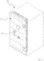
- FIG. 1 is a perspective view showing the structure of a safe applying a locking device of a door according to the present invention
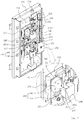
- FIGs. 2 to 4 are views illustrating the structure of a locking device of a door according to the present invention
- FIG. 5 is a view showing an intrusion type of an intruder for forcibly opening a safe which applies a locking device of a door according to the present invention.
- the locking device of a door 110 is provided to selectively lock a door 110 which opens or closes a storage space of an object and includes a locking means, a safety plate 270, an auxiliary locking part 260 and a reinforcing cover member 246.
- the object is a storage device for securing cash, securities, jewelry, important documents or the like, such as a general safe, an automated banking machine or the like.
- the automated banking machine is an automated machine such as a cash dispenser, an automatic teller machine or the like which can provide basic banking services such as deposit or withdrawal without a teller regardless of time and space in relation to financial services.
- a safe 100 applying a locking device of a door 110 according to the present invention will be described as an example.
- the safe 100 has a storage space with an open front side, and the opening on the front side of the storage space is configured to be opened and closed by the door 110 combined with the safe 100 through a hinge coupling.
- the safe 100 is configured to selectively constrain a closed state of the door 110 by the locking device of a door.
- the locking means is provided on the inner surface of the door 110 and configured to selectively constrain the door 110 to the safe 100, and the structure and features of the locking means can be changed diversely depending on required conditions and design specifications.
- the locking means may be understood as a concept including both a constraint element for directly constraining the door 110 and the safe 100 and a linking element provided to be linked to (or associated with) the constraint element so as to indirectly constrain the door 110 to the object.
- the locking means may be configured to include a sliding member 220, a door locking part 230 and a locking assembly 240.
- the sliding member 220 is provided to be parallel to the inner surface of the door 110 so that sliding movement is selectively allowed.
- a base plate 112 may be fixed to the inner surface of the door 110 in one piece, and the sliding member 220 may be provided so as to slidingly move on the base plate 112.
- a guide slot 222 may be formed in the sliding member 220, and a linking projection 232a may move along the guide slot 222 when the sliding member 220 slidingly moves, and a straight link member 232 may move in a straight direction as the linking projection 232a moves.
- the guide slot 222 may be formed in the shape of an inclined straight section with respect to the sliding direction of the sliding member 220, and the straight link member 232 may move straightly along the vertical direction as the linking projection 232a moves along the guide slot 222 when the sliding member 220 slidingly moves.
- the guide slot may be formed in the shape of a curved section, and the present invention is not limited or constrained by the shape and angle of the guide slot.
- a door handle 210 may be combined on the outer surface of the door 110 so as to be rotatably handled, and the sliding member 220 may be configured to be linked and slidingly move by the rotation handling of the door handle.
- the linking structure between the door handle 210 and the sliding member 220 may be changed diversely depending on required conditions and design specifications.
- a rotating piece 214 may be provided on the inner surface of the door 110 so as to rotate together with a shaft of the door handle 210 in one piece, and a guide slot 214a may be formed in the rotating piece 214.
- a guide projection 220a accommodated so as to move along the guide slot 214a may be formed in the sliding member 220. Accordingly, as the rotating piece 214 rotates by the rotation handling of the door handle 210, the sliding member 220 is linked and slidingly moves by the guide projection 220a which moves along the guide slot 214a.
- a door handle 210 provided to be rotatably handled is described as an example in an embodiment of the present invention, in some cases, the door handle may be provided so as to be slidingly handled, and it is also possible to configure to link and slidingly move the sliding member by the slide handling of the door handle.
- a constraint groove 221 may be formed at a side end of the sliding member 220, and as a locking journal 244 described below is constrained to the constraint groove 221 at a constraint position, sliding movement of the sliding member 220 may be constrained.
- the constraint groove 221 may be provided in a variety of shapes depending on required conditions and design specifications.
- the constraint groove 221 may be formed to penetrate the sliding member 220 along the inner direction of the door 110. That is, the constraint groove 221 may be formed in the shape of an open groove or step that can be constrained to the locking journal 244.
- a constraint groove 221 formed at an edge of a side end of the sliding member 220 will be described as an example.
- the inner direction of the door 110 may be understood as a direction perpendicular to the plate surface of the door 110 (or a direction penetrating the door 110).
- the constraint groove 221 may include a constraint wall 221a contacting with the locking journal 244, and the constraint wall 221a may be formed in one piece together with the sliding member 220 by bending a portion of the side end of the sliding member 220.
- the constraint groove 221 can be provided in the form of an open groove or step, interference can be minimized when the locking journal 244 described below enters the constraint groove 221.
- the constraint groove 221 when the constraint groove 221 is provided in the form of an open groove or step, the top and bottom sides thereof are open unlike a constraint groove formed in the shape of an enclosed hole, and thus interference generated by the surroundings of the constraint groove can be minimized.
- constraint groove provided in the form of an open groove or step that may constrain slide movement of the sliding member 220 simply with respect to the locking journal is described as an example in the embodiment of the present invention described above and shown in the figures, in some cases, the constraint groove itself may be formed in the shape of a kind of a hole or a cave which can accommodate an end portion of the locking journal therein.
- the door locking part 230 is provided on the inner surface of the door 110 to be linked by the slide movement of the sliding member 220 and selectively constrain the door 110 to the safe 100.
- the door locking part 230 is configured to include a straight link member 232 provided with a linking projection 232a moving along the guide slot 222 and linked by the slide movement of the sliding member 220 to move in a straight direction and a locking pin 234 connected to the straight link member 232 in one piece to move in a straight direction together with the straight link member 232 and selectively constraining the door 110 to the safe 100, and a binding groove (not shown) for accommodating a free end of the protruded locking pin 234 may be formed in the safe 100.
- a straight link member 232 provided on each of the upper and lower sides of the sliding member 220, linked by the slide movement of the sliding member 220, and moving straightly along the vertical direction will be described as an example.
- it may be configured to form a plurality of guide slots on the sliding member and move a plurality of straight link members straightly along each of the guide slots
- the present invention is not limited or constrained by the number of straight link members and a structure of disposing the straight link members.
- the door locking part 230 may further include a side surface locking pin 236 directly connected to an end portion of the sliding member 230 and selectively protruding toward the side surface of the door 110 according to slide movement of the sliding member 220, and a side surface binding groove (not shown) for accommodating the protruded side surface locking pin 236 may be formed in the safe 100.
- the locking assembly 240 is provided on the inner surface of the door 110 in order to selectively constrain the slide movement of the sliding member 220.
- the locking assembly 240 includes a locking body 242 fixed to the base plate 112, and a locking journal 244 moving to a constraint position constrained to the constraint groove 221 and a release position released from the constraint groove 221, in a direction straight with respect to the locking body 242.
- the slide movement of the sliding member 220 can be allowed when the locking journal 244 is disposed at the release position, and the slide movement of the sliding member 220 can be constrained when the locking journal 244 is disposed at the constraint position since the constraint groove 221 of the sliding member 220 is constrained to the locking journal 244.
- the slide movement of the sliding member 220 in the release direction can be constrained.
- constraint of the slide movement of the sliding member 220 in the release direction may be understood as a state of maintaining the locking state of the door 110 by the door locking part 230 described above.
- the locking journal may be configured to move from the release position to the constraint position in another method such as a rotation method.
- the locking journal 244 may have a variety of cross sectional shapes depending on required conditions and design specifications.
- the locking journal 244 may be provided to have a rectangular cross sectional shape.
- the locking journal may have a circular or non-circular shape, and the present invention is not limited or constrained by a cross sectional shape of the locking journal.
- the locking body 242 is mechanically or electrically connected to a locking module (not shown) installed on the outer surface of the door 110, the locking journal 244 may be selectively protruded by the operation of the locking module.
- a locking module (not shown) installed on the outer surface of the door 110
- the locking journal 244 may be selectively protruded by the operation of the locking module.
- a general key locking module, a dial style locking module, a keypad style locking module or the like which is generally used for a safe or the like can be used as the locking module so that only an authorized specific user may use.
- a cover member 250 may be provided on the inner surface of the door 110 to cover the locking journal 244, and since a penetration portion 252 through which the locking journal 244 passes is formed on the side surface of the cover member 250, movement of the locking journal 244 along the inner direction of the door 110 may be constrained by the penetration portion 252.
- the floating movement of the locking journal 244 along the inner direction may be understood as floating movement of the locking assembly 240 being lifted or separated from the door 110 by a forced shock applied from outside of the door 110.
- the shape of the cover member 250 having the penetration portion 252 may be changed diversely depending on required conditions and design specifications.
- the cover member 250 may be approximately formed in a " ⁇ " shape, and the penetration portion 252 of an open groove shape corresponding to the cross sectional shape of the locking journal 244 may be formed on both sides of the cover member 250.
- the locking journal 244 may pass through the penetration portion 252 and be disposed at the constraint position described above, and floating movement of the locking journal 244 along the inner direction of the door 110 may be constrained by the cover member 250 while the locking journal 244 is disposed at the constraint position.
- the penetration portion may be formed in a shape of a closed hole which may constrain the floating movement of the locking journal along the inner direction of the door.
- the safety plate 270 is provided on the inner surface of the door 110 so as to be broken when a forced shock from outside is sensed.
- the safety plate 270 may be provided between the inner surface of the door 110 and the base plate 112 and configured to be broken when a forced shock greater than a predetermined level is applied from outside.
- a safety plate 270 formed of a glass material that can be broken by a shock greater than a predetermined level will be described as an example.
- the safety plate may be formed of another material that can be broken by a shock greater than a predetermined level, and the present invention is not limited or constrained by a material or a characteristic of the safety plate.
- a binding portion 272 may be formed in the safety plate 270, and a binding projection 247 of the reinforcing cover member 246 described below may be bound to the binding portion 272.
- the binding portion 272 may be formed in a shape of a hole (or a groove) to which the binding projection 247 can be bound, in some cases, it can be formed in a shape of a projection.
- the auxiliary locking part 260 is configured to constrain the door 110 to the safe when the safety plate 270 is broken by a forced shock greater than a predetermined level which is applied from outside.
- the auxiliary locking part 260 may be configured to maintain the locking state of the door 110 by constraining the slide movement of the sliding member 220 when a forced shock greater than a predetermined level is sensed from outside.
- an auxiliary locking part 260 configured to include a locking member 262 provided on the inner surface of the door 110 so as to straightly move to a constraint position constraining slide movement of the sliding member 220 and a release position allowing the slide movement of the sliding member 220, a connection member 264 one end of which is connected to the safety plate 270 and the other end of which is connected to the locking member 262, and a locking spring 266 for providing elasticity so that the locking member 262 may move to the constraint position
- a constraint hole 226 may be formed at a side end of the sliding member 220, and the locking member 262 can be constrained to the constraint hole 226 when the locking member 262 is disposed at the constraint position.
- the locking member 262 Since the locking member 262 is provided so as to move in a straight direction from a constraint position constraining slide movement of the sliding member 220 to a release position allowing the slide movement of the sliding member 220 on the base plate 112, the locking member 262 disposed at the release position is supported by the connection member 264 to maintain the disposition state, and when the safety plate 270 is broken by a forced shock applied from outside, the locking member 262 may move to the constraint position by the elasticity of the locking spring 266.
- a pair of locking members 262 may be provided to be spaced apart from each other by a predetermined distance, and each of the locking members 262 may be connected to the safety plate 270 by the connection member 264.
- the locking spring 266 provides elasticity so that each of the locking members 262 may move to the constraint position, a state of disposing each of the locking members 262 at the release position may be maintained by the connection member 264 until the safety plate 270 is broken.
- the constrained state (a state of being constrained so as to be disposed at the release position) of each of the locking members 262 is released and, at the same time, each of the locking members 262 moves to the constraint position by the elasticity of the locking spring 266, and thus slide movement of the sliding member 220 may be constrained.
- the reinforcing cover member 246 is fixed to the inner surface of the door 110 to cover the locking means described above, and the reinforcing cover member 246 formed with a binding projection 247 bound to the binding portion 272.
- a reinforcing cover member 246 provided to cover the locking body 242 is described as an example. In some cases, the reinforcing cover member may be provided to cover another portion or part instead of the locking body.
- the binding projection 247 of the reinforcing cover member 246 may be bound to the binding portion 272 of the safety plate 270, when a forced shock greater than a predetermined level is applied to the reinforcing cover member 246, the safety plate 270 may be broken by the binding projection 247, and the door 110 may be constrained to the safe by the auxiliary locking part 260 described above.
- the reinforcing cover member 246 may be provided to cover the side surface of the locking body 242, and when a forced shock is applied to the reinforcing cover member 246 toward the side surface of the locking body 242, the safety plate 270 is broken by the binding projection 247, and the door 110 may be constrained to the safe by the auxiliary locking part 260.
- the reinforcing cover member 246 may be fixed to the base plate 112.
- a guide slot 112a may be formed in the base plate 112, and the binding projection 247 may pass through the guide slot 112a and be bound to the binding portion 272.
- the binding projection 247 may be provided in a variety of structures depending on required conditions and design specifications.
- the binding projection 247 may be approximately formed in an "L" shape, including a body portion 247a and a bent portion 247b bent at an end of the body portion 247a in one piece. Since the reinforcing cover member 246 slidingly moves along the guide slot 112a while the bent portion 247b passes through the guide slot 112a and the binding portion 272, the bent portion 247b may be constrained to the outer surface of the safety plate 270 facing the door 110.
- the auxiliary locking part 260 may operate by the safety plate 270 even when a shock is applied in a direction perpendicular to the plate surface of the door 110 (or in a direction penetrating the door) (e.g., when an external force is applied in a direction of tearing off the reinforcing cover member from the base plate), as well as when a shock is applied in a direction of the side surface of the locking body 242.
- a method of breaking the locking assembly 240 through an attack on the side surface of the safe can be expected. That is, as shown in FIG. 5 , a method of breaking the locking assembly 240 using a chisel and a hammer after making a hole on the outer wall of the side surface of the safe 100 with a drill can be expected. Since slide movement of the sliding member 220 can be allowed if the locking assembly 240 is broken like this, constraint of the door locking part 230 can be released using a handle.
- a shock force is delivered to the safety plate 270 through the binding projection 247, and the safety plate 270 can be broken, and since the auxiliary locking part 260 may operate thereby, the constrained state of the sliding member 220 can be maintained by the auxiliary locking part 260. Accordingly, the intruder should release the constrained state of the auxiliary locking part 260 or perform another release work in order to release the locking state of the door locking part 230. Accordingly, a time required to open the safe 100 is delayed as much, and the intruder cannot open the safe 100 within a short period of time as intended.
- an object in need of protection such as a safe or an automated banking machine may be safely protected.
- a locking state of a door may be stably maintained even when a forcible attack is applied on the side surface of the door. That is, according to the present invention, the reinforcing cover member covers the locking means, and when a forced shock is applied to the reinforcing cover member, the safety plate connected to the binding projection of the reinforcing cover member is broken, and the auxiliary locking part operates, and thus the locking state of the door may be further stably maintained.
- the disposition state of the locking assembly and the constrained state of the sliding member constrained by the locking assembly can be maintained, and a time for opening the safe by an intruder can be delayed as long as possible.
Landscapes
- Lock And Its Accessories (AREA)
Description
- The invention The present invention relates to a locking device of a door, and more specifically, to a locking device of a door for safely protecting an object in need of protection such as a safe or an automated banking machine.
- Generally, a safe is a device for securing cash, securities, jewelry, important documents or the like, which is frequently used for preventing intrusion of a third party other than a formal user.
- However, since techniques for illegally opening a safe are continuously improved in pace with techniques related to the safe are advanced, a safe which is further secure and further less probable to be robbed is required. Particularly, since automated banking machines which keep a large amount of cash are used in an open place, necessity of security on a safe is emphasized day by day.
- A primary object of a safe is to prevent a third party from opening the safe whatever apparatus and method may be used, and a secondary object is to delay opening the safe by dragging time as long as possible although the safe is opened until the police or a private security organization takes a proper action. In these days when various cutting machines and welding apparatuses are developed, it is rather almost impossible to perfectly prevent opening a safe, and delaying a time for opening the safe as long as possible may be the most realistic measure.
- For reference, observing the details related to Underwriters Laboratory (UL) certification, which is a specification related to safety in USA, it stipulates that a safe should not be opened by a safe expert for about thirty minutes to satisfy
security regulation level 1. That is, in the case of a machine such as a cash dispenser that is difficult to move as a whole, safely protecting a safe as long as possible is a task of top priority. DocumentDE 43 13 381 A1 discloses a locking device of a door comprising breakable safety plates and a reinforcement cover member. - The present invention provides a locking device of a door for safely protecting an object in need of protection such as a safe or an automated banking machine.
- Particularly, the present invention provides a locking device of a door for stably maintaining a locking state of the door even when a forced attack is applied on a side surface of the door.
- To accomplish the above objects, according to an aspect of the present invention, there is provided a locking device of a door for opening and closing a storage space of an object, the device including: a locking means provided on an inner surface of the door to selectively constrain the door to the object; a safety plate formed with a biding portion and provided on the inner surface of the door so as to be broken when a forced shock is applied from outside; an auxiliary locking part for constraining the door to the object when the safety plate is broken by the forced shock; and a reinforcing cover member formed with a binding projection bound to the binding portion in one piece, being fixed to the inner surface of the door so as to cover the locking means, in which when the forced shock is applied to the reinforcing cover member, the safety plate is broken, and the door is constrained to the object by the auxiliary locking part.
- Here, the object is a storage device for securing cash, securities, jewelry, important documents or the like, such as a general safe, an automated banking machine or the like.
- The structure and features of the locking means can be changed diversely depending on required conditions and design specifications. For reference, in the present invention, the locking means may be understood as a concept including both a constraint element for directly constraining the door and the safe and a linking element provided to be linked to (or associated with) the constraint element so as to indirectly constrain the door to the object. For example, the locking means may be configured to include a sliding member slidingly moving on the inner surface of the door; a door locking part provided on the inner surface of the door and linked by the slide movement of the sliding member to selectively constrain the door to the object; and a locking assembly provided on the inner surface of the door to selectively constrain the slide movement of the sliding member, in which the reinforcing cover member may be provided to cover the locking assembly.
- The door locking part may be provided in a variety of structures that can be linked by the slide movement of the sliding member and selectively constrain the door to the object. For example, the door locking part may be configured to include a straight link member linked by the slide movement of the sliding member and moving in a straight direction, a locking pin connected to the straight link member in one piece, moving in a straight direction together with the straight link member and selectively constraining the door to a safe, and a side surface locking pin directly connected to an end portion of the sliding member, selectively protruding toward a side surface of the door according to the slide movement of the sliding member, and constrained to the safe.
- The locking assembly may be provided in a variety of structures that can selectively constrain slide movement of the sliding member. For example, the locking assembly may be configured to include a locking body fixed to the inner surface of the door and a locking journal moving to a constraint position constraining the slide movement of the sliding member and a release position allowing the slide movement of the sliding member, in a direction straight with respect to the locking body. When the locking journal is disposed at the constraint position, the slide movement of the sliding member in the release direction can be constrained. Here, constraint of the slide movement of the sliding member in the release direction may be understood as a state of maintaining the locking state of the door by the door locking part.
- The safety plate may be configured to be broken when a forced shock greater than a predetermined level is applied. For example, the safety plate may be formed of a glass material that can be broken by a shock greater than a predetermined level. In some cases, the safety plate may be formed of another material that can be broken by a shock greater than a predetermined level, and the present invention is not limited or constrained by a material or a characteristic of the safety plate. In addition, a binding portion is formed in the safety plate, and a binding projection of the reinforcing cover member may be bound to the binding portion. Although the binding portion may be formed in a shape of a hole (or a groove) to which the binding projection can be bound, in some cases, it can be formed in a shape of a projection.
- The auxiliary locking part may be provided in a variety of structures that can constrain the door to the safe when the safety plate is broken by a forced shock greater than a predetermined level which is applied from outside. For example, the auxiliary locking part may be configured to maintain the locking state of the door by constraining the slide movement of the sliding member when a forced shock greater than a predetermined level is sensed from outside. For example, the auxiliary locking part may be configured to include a locking member provided on the inner surface of the door so as to move straightly to a constraint position constraining the slide movement of the sliding member and a release position allowing the slide movement of the sliding member; a connection member one end of which is connected to the safety plate and the other end of which is connected to the locking member; and a locking spring for providing elasticity so that the locking member may move to the constraint position, in which a state of disposing the locking member at the release position may be maintained by the connection member, and the locking member may move to the constraint position by the locking spring when the safety plate is broken.
- The reinforcing cover member may be provided to cover at least any one of parts configuring the locking means depending on required conditions and design specifications. For example, the reinforcing cover member may be provided to cover the side surface of the locking body, and when a forced shock is applied to the reinforcing cover member toward the side surface of the locking body, the auxiliary locking part operates as the safety plate is broken by the binding projection, and the door may be constrained to the object by the auxiliary locking part.
- In addition, a base plate may be fixed to the inner surface of the door, and the reinforcing cover member may be fixed to the base plate, and the safety plate may be disposed between the door and the base plate. In addition, a guide slot may be formed at the base plate, and the binding projection may pass through the guide slot and be bound to the binding portion.
- The binding projection may be provided in a variety of structures depending on required conditions and design specification. For example, the binding projection may be approximately formed in an "L" shape, including a body portion and a bent portion bent at an end of the body portion in one piece. Since the reinforcing cover member slidingly moves along the guide slot while the bent portion passes through the guide slot and the binding portion, the bent portion may be constrained to an outer surface of the safety plate facing the door.
-
-
FIG. 1 is a perspective view showing the structure of a safe applying a locking device of a door according to the present invention. -
FIGs. 2 to 4 are views illustrating the structure of a locking device of a door according to the present invention. -
FIG. 5 is a view showing an intrusion type of an intruder for forcibly opening a safe which applies a locking device of a door according to the present invention. - Reference will now be made in detail to exemplary embodiments of the present invention, examples of which are illustrated in the accompanying drawings, wherein like reference numerals refer to the like elements throughout. The exemplary embodiments are described below in order to explain the present invention by referring to the figures.
-
FIG. 1 is a perspective view showing the structure of a safe applying a locking device of a door according to the present invention,FIGs. 2 to 4 are views illustrating the structure of a locking device of a door according to the present invention, andFIG. 5 is a view showing an intrusion type of an intruder for forcibly opening a safe which applies a locking device of a door according to the present invention. - As shown in the figures, the locking device of a
door 110 according to the present invention is provided to selectively lock adoor 110 which opens or closes a storage space of an object and includes a locking means, asafety plate 270, anauxiliary locking part 260 and a reinforcingcover member 246. - For reference, the object is a storage device for securing cash, securities, jewelry, important documents or the like, such as a general safe, an automated banking machine or the like. In addition, the automated banking machine is an automated machine such as a cash dispenser, an automatic teller machine or the like which can provide basic banking services such as deposit or withdrawal without a teller regardless of time and space in relation to financial services. Hereinafter, a safe 100 applying a locking device of a
door 110 according to the present invention will be described as an example. - The safe 100 has a storage space with an open front side, and the opening on the front side of the storage space is configured to be opened and closed by the
door 110 combined with the safe 100 through a hinge coupling. The safe 100 is configured to selectively constrain a closed state of thedoor 110 by the locking device of a door. - The locking means is provided on the inner surface of the
door 110 and configured to selectively constrain thedoor 110 to the safe 100, and the structure and features of the locking means can be changed diversely depending on required conditions and design specifications. - For reference, in the present invention, the locking means may be understood as a concept including both a constraint element for directly constraining the
door 110 and the safe 100 and a linking element provided to be linked to (or associated with) the constraint element so as to indirectly constrain thedoor 110 to the object. For example, the locking means may be configured to include a slidingmember 220, adoor locking part 230 and alocking assembly 240. - The sliding
member 220 is provided to be parallel to the inner surface of thedoor 110 so that sliding movement is selectively allowed. - A
base plate 112 may be fixed to the inner surface of thedoor 110 in one piece, and the slidingmember 220 may be provided so as to slidingly move on thebase plate 112. - A
guide slot 222 may be formed in the slidingmember 220, and a linkingprojection 232a may move along theguide slot 222 when the slidingmember 220 slidingly moves, and astraight link member 232 may move in a straight direction as the linkingprojection 232a moves. For example, theguide slot 222 may be formed in the shape of an inclined straight section with respect to the sliding direction of the slidingmember 220, and thestraight link member 232 may move straightly along the vertical direction as the linkingprojection 232a moves along theguide slot 222 when the slidingmember 220 slidingly moves. In some cases, the guide slot may be formed in the shape of a curved section, and the present invention is not limited or constrained by the shape and angle of the guide slot. - In addition, a
door handle 210 may be combined on the outer surface of thedoor 110 so as to be rotatably handled, and the slidingmember 220 may be configured to be linked and slidingly move by the rotation handling of the door handle. - The linking structure between the
door handle 210 and the slidingmember 220 may be changed diversely depending on required conditions and design specifications. For example, a rotatingpiece 214 may be provided on the inner surface of thedoor 110 so as to rotate together with a shaft of thedoor handle 210 in one piece, and aguide slot 214a may be formed in therotating piece 214. In addition, a guide projection 220a accommodated so as to move along theguide slot 214a may be formed in the slidingmember 220. Accordingly, as therotating piece 214 rotates by the rotation handling of thedoor handle 210, the slidingmember 220 is linked and slidingly moves by the guide projection 220a which moves along theguide slot 214a. - Although a
door handle 210 provided to be rotatably handled is described as an example in an embodiment of the present invention, in some cases, the door handle may be provided so as to be slidingly handled, and it is also possible to configure to link and slidingly move the sliding member by the slide handling of the door handle. - In addition, a
constraint groove 221 may be formed at a side end of the slidingmember 220, and as alocking journal 244 described below is constrained to theconstraint groove 221 at a constraint position, sliding movement of the slidingmember 220 may be constrained. - The
constraint groove 221 may be provided in a variety of shapes depending on required conditions and design specifications. For example, theconstraint groove 221 may be formed to penetrate the slidingmember 220 along the inner direction of thedoor 110. That is, theconstraint groove 221 may be formed in the shape of an open groove or step that can be constrained to thelocking journal 244. Hereinafter, aconstraint groove 221 formed at an edge of a side end of the slidingmember 220 will be described as an example. For reference, in the present invention, the inner direction of thedoor 110 may be understood as a direction perpendicular to the plate surface of the door 110 (or a direction penetrating the door 110). - In addition, the
constraint groove 221 may include aconstraint wall 221a contacting with thelocking journal 244, and theconstraint wall 221a may be formed in one piece together with the slidingmember 220 by bending a portion of the side end of the slidingmember 220. - As described above, since the
constraint groove 221 can be provided in the form of an open groove or step, interference can be minimized when thelocking journal 244 described below enters theconstraint groove 221. In other words, when theconstraint groove 221 is provided in the form of an open groove or step, the top and bottom sides thereof are open unlike a constraint groove formed in the shape of an enclosed hole, and thus interference generated by the surroundings of the constraint groove can be minimized. - Although a constraint groove provided in the form of an open groove or step that may constrain slide movement of the sliding
member 220 simply with respect to the locking journal is described as an example in the embodiment of the present invention described above and shown in the figures, in some cases, the constraint groove itself may be formed in the shape of a kind of a hole or a cave which can accommodate an end portion of the locking journal therein. - The
door locking part 230 is provided on the inner surface of thedoor 110 to be linked by the slide movement of the slidingmember 220 and selectively constrain thedoor 110 to the safe 100. - The
door locking part 230 is configured to include astraight link member 232 provided with a linkingprojection 232a moving along theguide slot 222 and linked by the slide movement of the slidingmember 220 to move in a straight direction and alocking pin 234 connected to thestraight link member 232 in one piece to move in a straight direction together with thestraight link member 232 and selectively constraining thedoor 110 to the safe 100, and a binding groove (not shown) for accommodating a free end of the protruded lockingpin 234 may be formed in the safe 100. - Hereinafter, a
straight link member 232 provided on each of the upper and lower sides of the slidingmember 220, linked by the slide movement of the slidingmember 220, and moving straightly along the vertical direction will be described as an example. In some cases, although it may be configured to form a plurality of guide slots on the sliding member and move a plurality of straight link members straightly along each of the guide slots, the present invention is not limited or constrained by the number of straight link members and a structure of disposing the straight link members. - In addition, the
door locking part 230 may further include a sidesurface locking pin 236 directly connected to an end portion of the slidingmember 230 and selectively protruding toward the side surface of thedoor 110 according to slide movement of the slidingmember 220, and a side surface binding groove (not shown) for accommodating the protruded sidesurface locking pin 236 may be formed in the safe 100. - The locking
assembly 240 is provided on the inner surface of thedoor 110 in order to selectively constrain the slide movement of the slidingmember 220. For example, the lockingassembly 240 includes a lockingbody 242 fixed to thebase plate 112, and alocking journal 244 moving to a constraint position constrained to theconstraint groove 221 and a release position released from theconstraint groove 221, in a direction straight with respect to the lockingbody 242. That is, since thelocking journal 244 is provided to move straightly along a direction perpendicular to the sliding direction of the slidingmember 220 in front of the slidingmember 220, the slide movement of the slidingmember 220 can be allowed when thelocking journal 244 is disposed at the release position, and the slide movement of the slidingmember 220 can be constrained when thelocking journal 244 is disposed at the constraint position since theconstraint groove 221 of the slidingmember 220 is constrained to thelocking journal 244. In addition, when thelocking journal 244 is disposed at the constraint position, the slide movement of the slidingmember 220 in the release direction can be constrained. Here, constraint of the slide movement of the slidingmember 220 in the release direction may be understood as a state of maintaining the locking state of thedoor 110 by thedoor locking part 230 described above. - Although a locking journal configured to move in a straight direction with respect to the locking body is described as an example in an embodiment of the present invention, in some cases, the locking journal may be configured to move from the release position to the constraint position in another method such as a rotation method.
- The
locking journal 244 may have a variety of cross sectional shapes depending on required conditions and design specifications. For example, thelocking journal 244 may be provided to have a rectangular cross sectional shape. In some cases, the locking journal may have a circular or non-circular shape, and the present invention is not limited or constrained by a cross sectional shape of the locking journal. - In addition, since the locking
body 242 is mechanically or electrically connected to a locking module (not shown) installed on the outer surface of thedoor 110, thelocking journal 244 may be selectively protruded by the operation of the locking module. A general key locking module, a dial style locking module, a keypad style locking module or the like which is generally used for a safe or the like can be used as the locking module so that only an authorized specific user may use. - In addition, a
cover member 250 may be provided on the inner surface of thedoor 110 to cover thelocking journal 244, and since apenetration portion 252 through which thelocking journal 244 passes is formed on the side surface of thecover member 250, movement of thelocking journal 244 along the inner direction of thedoor 110 may be constrained by thepenetration portion 252. - For reference, the floating movement of the
locking journal 244 along the inner direction may be understood as floating movement of the lockingassembly 240 being lifted or separated from thedoor 110 by a forced shock applied from outside of thedoor 110. - The shape of the
cover member 250 having thepenetration portion 252 may be changed diversely depending on required conditions and design specifications. For example, thecover member 250 may be approximately formed in a "⊏" shape, and thepenetration portion 252 of an open groove shape corresponding to the cross sectional shape of thelocking journal 244 may be formed on both sides of thecover member 250. - Accordingly, the
locking journal 244 may pass through thepenetration portion 252 and be disposed at the constraint position described above, and floating movement of thelocking journal 244 along the inner direction of thedoor 110 may be constrained by thecover member 250 while thelocking journal 244 is disposed at the constraint position. - Although a penetration portion of the cover member formed in an open groove shape such as an approximate "U" shape is described as an example in an embodiment of the present invention, in some cases, the penetration portion may be formed in a shape of a closed hole which may constrain the floating movement of the locking journal along the inner direction of the door.
- The
safety plate 270 is provided on the inner surface of thedoor 110 so as to be broken when a forced shock from outside is sensed. For example, thesafety plate 270 may be provided between the inner surface of thedoor 110 and thebase plate 112 and configured to be broken when a forced shock greater than a predetermined level is applied from outside. Hereinafter, asafety plate 270 formed of a glass material that can be broken by a shock greater than a predetermined level will be described as an example. In some cases, the safety plate may be formed of another material that can be broken by a shock greater than a predetermined level, and the present invention is not limited or constrained by a material or a characteristic of the safety plate. - In addition, a binding
portion 272 may be formed in thesafety plate 270, and abinding projection 247 of the reinforcingcover member 246 described below may be bound to the bindingportion 272. Although thebinding portion 272 may be formed in a shape of a hole (or a groove) to which the bindingprojection 247 can be bound, in some cases, it can be formed in a shape of a projection. - The
auxiliary locking part 260 is configured to constrain thedoor 110 to the safe when thesafety plate 270 is broken by a forced shock greater than a predetermined level which is applied from outside. For example, theauxiliary locking part 260 may be configured to maintain the locking state of thedoor 110 by constraining the slide movement of the slidingmember 220 when a forced shock greater than a predetermined level is sensed from outside. - Hereinafter, an
auxiliary locking part 260 configured to include a lockingmember 262 provided on the inner surface of thedoor 110 so as to straightly move to a constraint position constraining slide movement of the slidingmember 220 and a release position allowing the slide movement of the slidingmember 220, aconnection member 264 one end of which is connected to thesafety plate 270 and the other end of which is connected to the lockingmember 262, and alocking spring 266 for providing elasticity so that the lockingmember 262 may move to the constraint position will be described as an example. In addition, aconstraint hole 226 may be formed at a side end of the slidingmember 220, and the lockingmember 262 can be constrained to theconstraint hole 226 when the lockingmember 262 is disposed at the constraint position. - Since the locking
member 262 is provided so as to move in a straight direction from a constraint position constraining slide movement of the slidingmember 220 to a release position allowing the slide movement of the slidingmember 220 on thebase plate 112, the lockingmember 262 disposed at the release position is supported by theconnection member 264 to maintain the disposition state, and when thesafety plate 270 is broken by a forced shock applied from outside, the lockingmember 262 may move to the constraint position by the elasticity of thelocking spring 266. - For example, a pair of locking
members 262 may be provided to be spaced apart from each other by a predetermined distance, and each of the lockingmembers 262 may be connected to thesafety plate 270 by theconnection member 264. Although thelocking spring 266 provides elasticity so that each of the lockingmembers 262 may move to the constraint position, a state of disposing each of the lockingmembers 262 at the release position may be maintained by theconnection member 264 until thesafety plate 270 is broken. However, when thesafety plate 270 is broken, the constrained state (a state of being constrained so as to be disposed at the release position) of each of the lockingmembers 262 is released and, at the same time, each of the lockingmembers 262 moves to the constraint position by the elasticity of thelocking spring 266, and thus slide movement of the slidingmember 220 may be constrained. - The reinforcing
cover member 246 is fixed to the inner surface of thedoor 110 to cover the locking means described above, and the reinforcingcover member 246 formed with abinding projection 247 bound to the bindingportion 272. Hereinafter, a reinforcingcover member 246 provided to cover thelocking body 242 is described as an example. In some cases, the reinforcing cover member may be provided to cover another portion or part instead of the locking body. - Since the binding
projection 247 of the reinforcingcover member 246 may be bound to the bindingportion 272 of thesafety plate 270, when a forced shock greater than a predetermined level is applied to the reinforcingcover member 246, thesafety plate 270 may be broken by the bindingprojection 247, and thedoor 110 may be constrained to the safe by theauxiliary locking part 260 described above. For example, the reinforcingcover member 246 may be provided to cover the side surface of the lockingbody 242, and when a forced shock is applied to the reinforcingcover member 246 toward the side surface of the lockingbody 242, thesafety plate 270 is broken by the bindingprojection 247, and thedoor 110 may be constrained to the safe by theauxiliary locking part 260. - In addition, the reinforcing
cover member 246 may be fixed to thebase plate 112. To this end, aguide slot 112a may be formed in thebase plate 112, and the bindingprojection 247 may pass through theguide slot 112a and be bound to the bindingportion 272. - The binding
projection 247 may be provided in a variety of structures depending on required conditions and design specifications. For example, the bindingprojection 247 may be approximately formed in an "L" shape, including abody portion 247a and abent portion 247b bent at an end of thebody portion 247a in one piece. Since the reinforcingcover member 246 slidingly moves along theguide slot 112a while thebent portion 247b passes through theguide slot 112a and the bindingportion 272, thebent portion 247b may be constrained to the outer surface of thesafety plate 270 facing thedoor 110. In such a structure, theauxiliary locking part 260 may operate by thesafety plate 270 even when a shock is applied in a direction perpendicular to the plate surface of the door 110 (or in a direction penetrating the door) (e.g., when an external force is applied in a direction of tearing off the reinforcing cover member from the base plate), as well as when a shock is applied in a direction of the side surface of the lockingbody 242. - Meanwhile, as a method of opening an object such as the safe 100 described above, a method of breaking the locking
assembly 240 through an attack on the side surface of the safe can be expected. That is, as shown inFIG. 5 , a method of breaking the lockingassembly 240 using a chisel and a hammer after making a hole on the outer wall of the side surface of the safe 100 with a drill can be expected. Since slide movement of the slidingmember 220 can be allowed if the lockingassembly 240 is broken like this, constraint of thedoor locking part 230 can be released using a handle. - However, in a structure in which the
locking body 242 is covered by the reinforcingcover member 246 and thesafety plate 270 can be broken when a shock is applied to the reinforcingcover member 246, a state of constraining the slide movement of the slidingmember 220 may be maintained comparatively stably although a forced shock is applied from outside. - That is, when a shock is applied to the reinforcing
cover member 246, a shock force is delivered to thesafety plate 270 through the bindingprojection 247, and thesafety plate 270 can be broken, and since theauxiliary locking part 260 may operate thereby, the constrained state of the slidingmember 220 can be maintained by theauxiliary locking part 260. Accordingly, the intruder should release the constrained state of theauxiliary locking part 260 or perform another release work in order to release the locking state of thedoor locking part 230. Accordingly, a time required to open the safe 100 is delayed as much, and the intruder cannot open the safe 100 within a short period of time as intended. - According to the locking device of a door of the present invention, an object in need of protection such as a safe or an automated banking machine may be safely protected.
- Particularly, according to the present invention, a locking state of a door may be stably maintained even when a forcible attack is applied on the side surface of the door. That is, according to the present invention, the reinforcing cover member covers the locking means, and when a forced shock is applied to the reinforcing cover member, the safety plate connected to the binding projection of the reinforcing cover member is broken, and the auxiliary locking part operates, and thus the locking state of the door may be further stably maintained.
- In addition, according to the present invention, although a forced shock is applied from outside, the disposition state of the locking assembly and the constrained state of the sliding member constrained by the locking assembly can be maintained, and a time for opening the safe by an intruder can be delayed as long as possible.
- While the present invention has been described with reference to the particular illustrative embodiments, it is not to be restricted by the embodiments but only by the appended claims.
Claims (7)
- A locking device of a door (110) for opening and closing a storage space of an object, the device comprising:a locking means provided on an inner surface of the door (110) to selectively constrain the door (110) to the object;a safety plate (270) formed with a binding portion (272) and provided on the inner surface of the door (110) so as to be broken when a forced shock is applied from outside;an auxiliary locking part for constraining the door (110) to the object when the safety plate (270) is broken by the forced shock; anda reinforcing cover member (246) formed with a binding projection (247) bound to the binding portion (272); being fixed to the inner surface of the door (110) so as to cover the locking means, wherein when the forced shock is applied to the reinforcing cover member (246), the safety plate (270) is broken, and the door (110) is constrained to the object by the auxiliary locking part.
- The device according to claim 1, further comprising a base plate (112) fixed to the inner surface of the door (110), wherein the reinforcing cover member (246) is fixed to the base plate (112), and the safety plate (270) is disposed between the door (110) and the base plate (112), wherein a guide slot (112A) is formed in the base plate (112), and the binding projection (247) passes through the guide slot (112A) and is bound to the binding portion (272).
- The device according to claim 2, wherein the binding projection (247) includes:a body portion (247A); anda bent portion (247B) bent at an end of the body portion (247A), wherein as the reinforcing cover member (246) slidingly moves along the guide slot (112A) after the bent portion (247B) passes through the guide slot (112A) and the binding portion (272), the bent portion (247B) is constrained to an outer surface of the safety plate (270) facing the door (110).
- The device according to any one of the preceding claims, wherein the reinforcing cover member (246) is provided to cover a side surface of the locking means, and when a forced shock is applied to the reinforcing cover member (246) toward the side surface of the locking means, the safety plate (270) is broken by the binding projection (247), and the door (110) is constrained to the object by the auxiliary locking part.
- The device according to any one of the preceding claims, wherein the locking means includes:a sliding member (220) slidingly moving on the inner surface of the door (110) ; a door locking part provided on the inner surface of the door (110) and linked by the slide movement of the sliding member (220) to selectively constrain the door (110) to the object; anda locking assembly (240) provided on the inner surface of the door sliding member to selectively constrain the slide movement of the sliding member (220), wherein the reinforcing cover member (246) is provided to cover the locking assembly (240).
- The device according to claim 5, wherein the locking assembly (240) includes:a locking body (242) fixed to the inner surface of the door (110); anda locking journal (244) moving to a constraint position constraining the slide movement of the sliding member (220) and a release position allowing the slide movement of the sliding member (220), in a direction straight with respect to the locking body (242).
- The device according to claim 5 or 6, wherein the auxiliary locking part includes:a locking member (262) provided on the inner surface of the door (110) so as to move straightly to a constraint position constraining the slide movement of the sliding member (220) and a release position allowing the slide movement of the sliding member (220); a connection member (264) one end of which is connected to the safety plate (270) and the other end of which is connected to the locking member (262); anda locking spring (266) for providing elasticity so that the locking member (262) may move to the constraint position, wherein a state of disposing the locking member (262) at the release position may be maintained by the connection member, and the locking member moves to the constraint position by the locking spring when the safety plate (270) is broken.
Applications Claiming Priority (1)
| Application Number | Priority Date | Filing Date | Title |
|---|---|---|---|
| KR1020120035421A KR101306900B1 (en) | 2012-04-05 | 2012-04-05 | Locking device for door |
Publications (2)
| Publication Number | Publication Date |
|---|---|
| EP2650459A1 EP2650459A1 (en) | 2013-10-16 |
| EP2650459B1 true EP2650459B1 (en) | 2018-06-27 |
Family
ID=48082942
Family Applications (1)
| Application Number | Title | Priority Date | Filing Date |
|---|---|---|---|
| EP13162536.0A Not-in-force EP2650459B1 (en) | 2012-04-05 | 2013-04-05 | Locking device of a door |
Country Status (2)
| Country | Link |
|---|---|
| EP (1) | EP2650459B1 (en) |
| KR (1) | KR101306900B1 (en) |
Cited By (1)
| Publication number | Priority date | Publication date | Assignee | Title |
|---|---|---|---|---|
| US12196531B2 (en) | 2020-07-17 | 2025-01-14 | ProtectEd Solutions LLC | Protective cabinet |
Families Citing this family (4)
| Publication number | Priority date | Publication date | Assignee | Title |
|---|---|---|---|---|
| KR101623639B1 (en) | 2014-06-27 | 2016-05-23 | 주식회사 엘지씨엔에스 | Sensing impulse device and safe having thereof |
| CN112878858B (en) * | 2021-01-15 | 2022-03-15 | 江西阳光安全设备集团有限公司 | A kind of reinforcement structure of safe cabinet lock |
| KR20230041301A (en) * | 2021-09-17 | 2023-03-24 | 효성티앤에스 주식회사 | Door for safe and safe including the same |
| KR20250177660A (en) * | 2024-06-17 | 2025-12-24 | 효성티앤에스 주식회사 | A safe of automated teller machine |
Family Cites Families (10)
| Publication number | Priority date | Publication date | Assignee | Title |
|---|---|---|---|---|
| GB2146689B (en) * | 1983-07-26 | 1987-04-01 | Vardeskydd Ab | Vault door locks |
| FR2564890B1 (en) * | 1984-05-23 | 1986-10-24 | Fichet Bauche | DEVICE FOR PROTECTING A SECURITY AGENT AGAINST ASSAULT. |
| GB8520131D0 (en) * | 1985-08-10 | 1985-09-18 | Chubb & Sons Lock & Safe Co | Locking mechanism |
| DE9204933U1 (en) * | 1992-04-09 | 1992-06-17 | Adolphs GmbH + Co. KG, 4030 Ratingen | Safety device for a door lock |
| DE4313381A1 (en) * | 1993-04-23 | 1994-10-27 | Leicher Gmbh & Co | Locking mechanism |
| JPH10153022A (en) * | 1996-11-21 | 1998-06-09 | Oki Electric Ind Co Ltd | Lock mechanism of door and crime prevention equipment device |
| DE20116334U1 (en) * | 2001-10-05 | 2001-12-20 | Carl Wittkopp-Gmbh & Co Kg, 42551 Velbert | Bolt work for security boxes |
| KR20090002449A (en) * | 2007-06-29 | 2009-01-09 | 노틸러스효성 주식회사 | Door lock structure |
| JP2010229677A (en) * | 2009-03-26 | 2010-10-14 | Oki Electric Ind Co Ltd | Relocking mechanism of safe door |
| KR20120101256A (en) * | 2011-03-04 | 2012-09-13 | 노틸러스효성 주식회사 | Locking device for door |
-
2012
- 2012-04-05 KR KR1020120035421A patent/KR101306900B1/en active Active
-
2013
- 2013-04-05 EP EP13162536.0A patent/EP2650459B1/en not_active Not-in-force
Non-Patent Citations (1)
| Title |
|---|
| None * |
Cited By (1)
| Publication number | Priority date | Publication date | Assignee | Title |
|---|---|---|---|---|
| US12196531B2 (en) | 2020-07-17 | 2025-01-14 | ProtectEd Solutions LLC | Protective cabinet |
Also Published As
| Publication number | Publication date |
|---|---|
| EP2650459A1 (en) | 2013-10-16 |
| KR101306900B1 (en) | 2013-09-10 |
Similar Documents
| Publication | Publication Date | Title |
|---|---|---|
| EP2647788B1 (en) | Locking device of a door | |
| EP2650459A1 (en) | Locking device of a door | |
| KR101306902B1 (en) | Locking device for door | |
| US8151608B2 (en) | Electronic lock box with mechanism immobilizer features | |
| EP1860267A2 (en) | Locking device for door | |
| EP1854946A2 (en) | Door lock structure | |
| KR101810694B1 (en) | Door for safe | |
| KR20130113111A (en) | Locking device for door | |
| KR20090002449A (en) | Door lock structure | |
| JP5405961B2 (en) | Anti-theft device and anti-theft fee settlement system | |
| KR20130113105A (en) | Locking device for door | |
| KR100869609B1 (en) | Door lock structure | |
| KR20130035505A (en) | Locking device for door | |
| KR101325682B1 (en) | Locking device for door | |
| KR101306901B1 (en) | Locking device for door | |
| KR20120101256A (en) | Locking device for door | |
| KR100726004B1 (en) | Door lock | |
| EP3548681B1 (en) | Tamper evident locking device | |
| KR20140086422A (en) | Locking device for door | |
| KR20110132707A (en) | Door lock | |
| KR20050115537A (en) | Door having double lock function | |
| KR100716755B1 (en) | Door lock structure | |
| US20200248485A1 (en) | Cargo Door Protective Handle and Hasp Cover | |
| KR20120094808A (en) | Door locking apparatus of automated teller machine | |
| KR20140086427A (en) | Double locking device for door |
Legal Events
| Date | Code | Title | Description |
|---|---|---|---|
| PUAI | Public reference made under article 153(3) epc to a published international application that has entered the european phase |
Free format text: ORIGINAL CODE: 0009012 |
|
| AK | Designated contracting states |
Kind code of ref document: A1 Designated state(s): AL AT BE BG CH CY CZ DE DK EE ES FI FR GB GR HR HU IE IS IT LI LT LU LV MC MK MT NL NO PL PT RO RS SE SI SK SM TR |
|
| AX | Request for extension of the european patent |
Extension state: BA ME |
|
| 17P | Request for examination filed |
Effective date: 20140203 |
|
| RBV | Designated contracting states (corrected) |
Designated state(s): AL AT BE BG CH CY CZ DE DK EE ES FI FR GB GR HR HU IE IS IT LI LT LU LV MC MK MT NL NO PL PT RO RS SE SI SK SM TR |
|
| RIC1 | Information provided on ipc code assigned before grant |
Ipc: E05B 17/20 20060101ALI20180118BHEP Ipc: E05B 65/00 20060101AFI20180118BHEP |
|
| GRAP | Despatch of communication of intention to grant a patent |
Free format text: ORIGINAL CODE: EPIDOSNIGR1 |
|
| STAA | Information on the status of an ep patent application or granted ep patent |
Free format text: STATUS: GRANT OF PATENT IS INTENDED |
|
| INTG | Intention to grant announced |
Effective date: 20180223 |
|
| GRAS | Grant fee paid |
Free format text: ORIGINAL CODE: EPIDOSNIGR3 |
|
| GRAA | (expected) grant |
Free format text: ORIGINAL CODE: 0009210 |
|
| STAA | Information on the status of an ep patent application or granted ep patent |
Free format text: STATUS: THE PATENT HAS BEEN GRANTED |
|
| RAP1 | Party data changed (applicant data changed or rights of an application transferred) |
Owner name: HYOSUNG TNS INC. |
|
| AK | Designated contracting states |
Kind code of ref document: B1 Designated state(s): AL AT BE BG CH CY CZ DE DK EE ES FI FR GB GR HR HU IE IS IT LI LT LU LV MC MK MT NL NO PL PT RO RS SE SI SK SM TR |
|
| REG | Reference to a national code |
Ref country code: GB Ref legal event code: FG4D |
|
| REG | Reference to a national code |
Ref country code: AT Ref legal event code: REF Ref document number: 1012501 Country of ref document: AT Kind code of ref document: T Effective date: 20180715 |
|
| REG | Reference to a national code |
Ref country code: IE Ref legal event code: FG4D |
|
| REG | Reference to a national code |
Ref country code: DE Ref legal event code: R096 Ref document number: 602013039322 Country of ref document: DE |
|
| PG25 | Lapsed in a contracting state [announced via postgrant information from national office to epo] |
Ref country code: FI Free format text: LAPSE BECAUSE OF FAILURE TO SUBMIT A TRANSLATION OF THE DESCRIPTION OR TO PAY THE FEE WITHIN THE PRESCRIBED TIME-LIMIT Effective date: 20180627 Ref country code: BG Free format text: LAPSE BECAUSE OF FAILURE TO SUBMIT A TRANSLATION OF THE DESCRIPTION OR TO PAY THE FEE WITHIN THE PRESCRIBED TIME-LIMIT Effective date: 20180927 Ref country code: NO Free format text: LAPSE BECAUSE OF FAILURE TO SUBMIT A TRANSLATION OF THE DESCRIPTION OR TO PAY THE FEE WITHIN THE PRESCRIBED TIME-LIMIT Effective date: 20180927 Ref country code: SE Free format text: LAPSE BECAUSE OF FAILURE TO SUBMIT A TRANSLATION OF THE DESCRIPTION OR TO PAY THE FEE WITHIN THE PRESCRIBED TIME-LIMIT Effective date: 20180627 Ref country code: LT Free format text: LAPSE BECAUSE OF FAILURE TO SUBMIT A TRANSLATION OF THE DESCRIPTION OR TO PAY THE FEE WITHIN THE PRESCRIBED TIME-LIMIT Effective date: 20180627 |
|
| REG | Reference to a national code |
Ref country code: NL Ref legal event code: MP Effective date: 20180627 |
|
| REG | Reference to a national code |
Ref country code: LT Ref legal event code: MG4D |
|
| PG25 | Lapsed in a contracting state [announced via postgrant information from national office to epo] |
Ref country code: LV Free format text: LAPSE BECAUSE OF FAILURE TO SUBMIT A TRANSLATION OF THE DESCRIPTION OR TO PAY THE FEE WITHIN THE PRESCRIBED TIME-LIMIT Effective date: 20180627 Ref country code: RS Free format text: LAPSE BECAUSE OF FAILURE TO SUBMIT A TRANSLATION OF THE DESCRIPTION OR TO PAY THE FEE WITHIN THE PRESCRIBED TIME-LIMIT Effective date: 20180627 Ref country code: HR Free format text: LAPSE BECAUSE OF FAILURE TO SUBMIT A TRANSLATION OF THE DESCRIPTION OR TO PAY THE FEE WITHIN THE PRESCRIBED TIME-LIMIT Effective date: 20180627 Ref country code: GR Free format text: LAPSE BECAUSE OF FAILURE TO SUBMIT A TRANSLATION OF THE DESCRIPTION OR TO PAY THE FEE WITHIN THE PRESCRIBED TIME-LIMIT Effective date: 20180928 |
|
| REG | Reference to a national code |
Ref country code: AT Ref legal event code: MK05 Ref document number: 1012501 Country of ref document: AT Kind code of ref document: T Effective date: 20180627 |
|
| PG25 | Lapsed in a contracting state [announced via postgrant information from national office to epo] |
Ref country code: NL Free format text: LAPSE BECAUSE OF FAILURE TO SUBMIT A TRANSLATION OF THE DESCRIPTION OR TO PAY THE FEE WITHIN THE PRESCRIBED TIME-LIMIT Effective date: 20180627 |
|
| PG25 | Lapsed in a contracting state [announced via postgrant information from national office to epo] |
Ref country code: RO Free format text: LAPSE BECAUSE OF FAILURE TO SUBMIT A TRANSLATION OF THE DESCRIPTION OR TO PAY THE FEE WITHIN THE PRESCRIBED TIME-LIMIT Effective date: 20180627 Ref country code: AT Free format text: LAPSE BECAUSE OF FAILURE TO SUBMIT A TRANSLATION OF THE DESCRIPTION OR TO PAY THE FEE WITHIN THE PRESCRIBED TIME-LIMIT Effective date: 20180627 Ref country code: EE Free format text: LAPSE BECAUSE OF FAILURE TO SUBMIT A TRANSLATION OF THE DESCRIPTION OR TO PAY THE FEE WITHIN THE PRESCRIBED TIME-LIMIT Effective date: 20180627 Ref country code: IS Free format text: LAPSE BECAUSE OF FAILURE TO SUBMIT A TRANSLATION OF THE DESCRIPTION OR TO PAY THE FEE WITHIN THE PRESCRIBED TIME-LIMIT Effective date: 20181027 Ref country code: CZ Free format text: LAPSE BECAUSE OF FAILURE TO SUBMIT A TRANSLATION OF THE DESCRIPTION OR TO PAY THE FEE WITHIN THE PRESCRIBED TIME-LIMIT Effective date: 20180627 Ref country code: SK Free format text: LAPSE BECAUSE OF FAILURE TO SUBMIT A TRANSLATION OF THE DESCRIPTION OR TO PAY THE FEE WITHIN THE PRESCRIBED TIME-LIMIT Effective date: 20180627 Ref country code: PL Free format text: LAPSE BECAUSE OF FAILURE TO SUBMIT A TRANSLATION OF THE DESCRIPTION OR TO PAY THE FEE WITHIN THE PRESCRIBED TIME-LIMIT Effective date: 20180627 |
|
| PG25 | Lapsed in a contracting state [announced via postgrant information from national office to epo] |
Ref country code: SM Free format text: LAPSE BECAUSE OF FAILURE TO SUBMIT A TRANSLATION OF THE DESCRIPTION OR TO PAY THE FEE WITHIN THE PRESCRIBED TIME-LIMIT Effective date: 20180627 Ref country code: ES Free format text: LAPSE BECAUSE OF FAILURE TO SUBMIT A TRANSLATION OF THE DESCRIPTION OR TO PAY THE FEE WITHIN THE PRESCRIBED TIME-LIMIT Effective date: 20180627 |
|
| REG | Reference to a national code |
Ref country code: DE Ref legal event code: R097 Ref document number: 602013039322 Country of ref document: DE |
|
| PLBE | No opposition filed within time limit |
Free format text: ORIGINAL CODE: 0009261 |
|
| STAA | Information on the status of an ep patent application or granted ep patent |
Free format text: STATUS: NO OPPOSITION FILED WITHIN TIME LIMIT |
|
| PG25 | Lapsed in a contracting state [announced via postgrant information from national office to epo] |
Ref country code: DK Free format text: LAPSE BECAUSE OF FAILURE TO SUBMIT A TRANSLATION OF THE DESCRIPTION OR TO PAY THE FEE WITHIN THE PRESCRIBED TIME-LIMIT Effective date: 20180627 |
|
| 26N | No opposition filed |
Effective date: 20190328 |
|
| PG25 | Lapsed in a contracting state [announced via postgrant information from national office to epo] |
Ref country code: SI Free format text: LAPSE BECAUSE OF FAILURE TO SUBMIT A TRANSLATION OF THE DESCRIPTION OR TO PAY THE FEE WITHIN THE PRESCRIBED TIME-LIMIT Effective date: 20180627 |
|
| PG25 | Lapsed in a contracting state [announced via postgrant information from national office to epo] |
Ref country code: AL Free format text: LAPSE BECAUSE OF FAILURE TO SUBMIT A TRANSLATION OF THE DESCRIPTION OR TO PAY THE FEE WITHIN THE PRESCRIBED TIME-LIMIT Effective date: 20180627 |
|
| REG | Reference to a national code |
Ref country code: CH Ref legal event code: PL |
|
| REG | Reference to a national code |
Ref country code: BE Ref legal event code: MM Effective date: 20190430 |
|
| GBPC | Gb: european patent ceased through non-payment of renewal fee |
Effective date: 20190405 |
|
| PG25 | Lapsed in a contracting state [announced via postgrant information from national office to epo] |
Ref country code: LU Free format text: LAPSE BECAUSE OF NON-PAYMENT OF DUE FEES Effective date: 20190405 Ref country code: MC Free format text: LAPSE BECAUSE OF FAILURE TO SUBMIT A TRANSLATION OF THE DESCRIPTION OR TO PAY THE FEE WITHIN THE PRESCRIBED TIME-LIMIT Effective date: 20180627 |
|
| PG25 | Lapsed in a contracting state [announced via postgrant information from national office to epo] |
Ref country code: LI Free format text: LAPSE BECAUSE OF NON-PAYMENT OF DUE FEES Effective date: 20190430 Ref country code: GB Free format text: LAPSE BECAUSE OF NON-PAYMENT OF DUE FEES Effective date: 20190405 Ref country code: CH Free format text: LAPSE BECAUSE OF NON-PAYMENT OF DUE FEES Effective date: 20190430 |
|
| PG25 | Lapsed in a contracting state [announced via postgrant information from national office to epo] |
Ref country code: FR Free format text: LAPSE BECAUSE OF NON-PAYMENT OF DUE FEES Effective date: 20190430 Ref country code: BE Free format text: LAPSE BECAUSE OF NON-PAYMENT OF DUE FEES Effective date: 20190430 |
|
| PG25 | Lapsed in a contracting state [announced via postgrant information from national office to epo] |
Ref country code: TR Free format text: LAPSE BECAUSE OF FAILURE TO SUBMIT A TRANSLATION OF THE DESCRIPTION OR TO PAY THE FEE WITHIN THE PRESCRIBED TIME-LIMIT Effective date: 20180627 |
|
| PG25 | Lapsed in a contracting state [announced via postgrant information from national office to epo] |
Ref country code: IE Free format text: LAPSE BECAUSE OF NON-PAYMENT OF DUE FEES Effective date: 20190405 |
|
| PG25 | Lapsed in a contracting state [announced via postgrant information from national office to epo] |
Ref country code: PT Free format text: LAPSE BECAUSE OF FAILURE TO SUBMIT A TRANSLATION OF THE DESCRIPTION OR TO PAY THE FEE WITHIN THE PRESCRIBED TIME-LIMIT Effective date: 20181029 |
|
| PG25 | Lapsed in a contracting state [announced via postgrant information from national office to epo] |
Ref country code: CY Free format text: LAPSE BECAUSE OF FAILURE TO SUBMIT A TRANSLATION OF THE DESCRIPTION OR TO PAY THE FEE WITHIN THE PRESCRIBED TIME-LIMIT Effective date: 20180627 |
|
| PG25 | Lapsed in a contracting state [announced via postgrant information from national office to epo] |
Ref country code: HU Free format text: LAPSE BECAUSE OF FAILURE TO SUBMIT A TRANSLATION OF THE DESCRIPTION OR TO PAY THE FEE WITHIN THE PRESCRIBED TIME-LIMIT; INVALID AB INITIO Effective date: 20130405 Ref country code: MT Free format text: LAPSE BECAUSE OF FAILURE TO SUBMIT A TRANSLATION OF THE DESCRIPTION OR TO PAY THE FEE WITHIN THE PRESCRIBED TIME-LIMIT Effective date: 20180627 |
|
| PG25 | Lapsed in a contracting state [announced via postgrant information from national office to epo] |
Ref country code: MK Free format text: LAPSE BECAUSE OF FAILURE TO SUBMIT A TRANSLATION OF THE DESCRIPTION OR TO PAY THE FEE WITHIN THE PRESCRIBED TIME-LIMIT Effective date: 20180627 |
|
| PGFP | Annual fee paid to national office [announced via postgrant information from national office to epo] |
Ref country code: IT Payment date: 20230321 Year of fee payment: 11 |
|
| PGFP | Annual fee paid to national office [announced via postgrant information from national office to epo] |
Ref country code: DE Payment date: 20230320 Year of fee payment: 11 |
|
| REG | Reference to a national code |
Ref country code: DE Ref legal event code: R119 Ref document number: 602013039322 Country of ref document: DE |
|
| PG25 | Lapsed in a contracting state [announced via postgrant information from national office to epo] |
Ref country code: DE Free format text: LAPSE BECAUSE OF NON-PAYMENT OF DUE FEES Effective date: 20241105 |
|
| PG25 | Lapsed in a contracting state [announced via postgrant information from national office to epo] |
Ref country code: DE Free format text: LAPSE BECAUSE OF NON-PAYMENT OF DUE FEES Effective date: 20241105 |
|
| PG25 | Lapsed in a contracting state [announced via postgrant information from national office to epo] |
Ref country code: IT Free format text: LAPSE BECAUSE OF NON-PAYMENT OF DUE FEES Effective date: 20240405 |