EP2650344A1 - Fuel production system - Google Patents
Fuel production system Download PDFInfo
- Publication number
- EP2650344A1 EP2650344A1 EP10860422.4A EP10860422A EP2650344A1 EP 2650344 A1 EP2650344 A1 EP 2650344A1 EP 10860422 A EP10860422 A EP 10860422A EP 2650344 A1 EP2650344 A1 EP 2650344A1
- Authority
- EP
- European Patent Office
- Prior art keywords
- amino group
- electrolytic solution
- hydrogen
- formula
- group
- Prior art date
- Legal status (The legal status is an assumption and is not a legal conclusion. Google has not performed a legal analysis and makes no representation as to the accuracy of the status listed.)
- Withdrawn
Links
- 0 CCCCC(CCC)C(*)(C(*)C1)C(*)C=*1O Chemical compound CCCCC(CCC)C(*)(C(*)C1)C(*)C=*1O 0.000 description 1
Images


Classifications
-
- C—CHEMISTRY; METALLURGY
- C25—ELECTROLYTIC OR ELECTROPHORETIC PROCESSES; APPARATUS THEREFOR
- C25B—ELECTROLYTIC OR ELECTROPHORETIC PROCESSES FOR THE PRODUCTION OF COMPOUNDS OR NON-METALS; APPARATUS THEREFOR
- C25B1/00—Electrolytic production of inorganic compounds or non-metals
-
- C—CHEMISTRY; METALLURGY
- C25—ELECTROLYTIC OR ELECTROPHORETIC PROCESSES; APPARATUS THEREFOR
- C25B—ELECTROLYTIC OR ELECTROPHORETIC PROCESSES FOR THE PRODUCTION OF COMPOUNDS OR NON-METALS; APPARATUS THEREFOR
- C25B1/00—Electrolytic production of inorganic compounds or non-metals
- C25B1/01—Products
- C25B1/02—Hydrogen or oxygen
- C25B1/04—Hydrogen or oxygen by electrolysis of water
-
- C—CHEMISTRY; METALLURGY
- C10—PETROLEUM, GAS OR COKE INDUSTRIES; TECHNICAL GASES CONTAINING CARBON MONOXIDE; FUELS; LUBRICANTS; PEAT
- C10G—CRACKING HYDROCARBON OILS; PRODUCTION OF LIQUID HYDROCARBON MIXTURES, e.g. BY DESTRUCTIVE HYDROGENATION, OLIGOMERISATION, POLYMERISATION; RECOVERY OF HYDROCARBON OILS FROM OIL-SHALE, OIL-SAND, OR GASES; REFINING MIXTURES MAINLY CONSISTING OF HYDROCARBONS; REFORMING OF NAPHTHA; MINERAL WAXES
- C10G2/00—Production of liquid hydrocarbon mixtures of undefined composition from oxides of carbon
- C10G2/30—Production of liquid hydrocarbon mixtures of undefined composition from oxides of carbon from carbon monoxide with hydrogen
- C10G2/32—Production of liquid hydrocarbon mixtures of undefined composition from oxides of carbon from carbon monoxide with hydrogen with the use of catalysts
-
- C—CHEMISTRY; METALLURGY
- C25—ELECTROLYTIC OR ELECTROPHORETIC PROCESSES; APPARATUS THEREFOR
- C25B—ELECTROLYTIC OR ELECTROPHORETIC PROCESSES FOR THE PRODUCTION OF COMPOUNDS OR NON-METALS; APPARATUS THEREFOR
- C25B1/00—Electrolytic production of inorganic compounds or non-metals
- C25B1/01—Products
-
- C—CHEMISTRY; METALLURGY
- C25—ELECTROLYTIC OR ELECTROPHORETIC PROCESSES; APPARATUS THEREFOR
- C25B—ELECTROLYTIC OR ELECTROPHORETIC PROCESSES FOR THE PRODUCTION OF COMPOUNDS OR NON-METALS; APPARATUS THEREFOR
- C25B1/00—Electrolytic production of inorganic compounds or non-metals
- C25B1/01—Products
- C25B1/23—Carbon monoxide or syngas
-
- C—CHEMISTRY; METALLURGY
- C25—ELECTROLYTIC OR ELECTROPHORETIC PROCESSES; APPARATUS THEREFOR
- C25B—ELECTROLYTIC OR ELECTROPHORETIC PROCESSES FOR THE PRODUCTION OF COMPOUNDS OR NON-METALS; APPARATUS THEREFOR
- C25B9/00—Cells or assemblies of cells; Constructional parts of cells; Assemblies of constructional parts, e.g. electrode-diaphragm assemblies; Process-related cell features
- C25B9/17—Cells comprising dimensionally-stable non-movable electrodes; Assemblies of constructional parts thereof
- C25B9/19—Cells comprising dimensionally-stable non-movable electrodes; Assemblies of constructional parts thereof with diaphragms
- C25B9/23—Cells comprising dimensionally-stable non-movable electrodes; Assemblies of constructional parts thereof with diaphragms comprising ion-exchange membranes in or on which electrode material is embedded
-
- Y—GENERAL TAGGING OF NEW TECHNOLOGICAL DEVELOPMENTS; GENERAL TAGGING OF CROSS-SECTIONAL TECHNOLOGIES SPANNING OVER SEVERAL SECTIONS OF THE IPC; TECHNICAL SUBJECTS COVERED BY FORMER USPC CROSS-REFERENCE ART COLLECTIONS [XRACs] AND DIGESTS
- Y02—TECHNOLOGIES OR APPLICATIONS FOR MITIGATION OR ADAPTATION AGAINST CLIMATE CHANGE
- Y02E—REDUCTION OF GREENHOUSE GAS [GHG] EMISSIONS, RELATED TO ENERGY GENERATION, TRANSMISSION OR DISTRIBUTION
- Y02E60/00—Enabling technologies; Technologies with a potential or indirect contribution to GHG emissions mitigation
- Y02E60/30—Hydrogen technology
- Y02E60/36—Hydrogen production from non-carbon containing sources, e.g. by water electrolysis
Definitions
- the present invention relates to a fuel manufacturing system. More particularly, the present invention relates to a fuel manufacturing system for synthesizing the fuel from H 2 and CO generated by electrolysis.
- Fossil fuels including petroleum, coal, natural gas and the like are used as a material for generating heat or electricity, and fuels for transportation so as to support the modern energy consumption society.
- fossil fuels are exhaustible fuels and their reserves are limited. Thus, it is needless to say that preparation is needed for depletion of the fossil fuels.
- emissions of CO 2 caused by combustion of the fossil fuels into the atmosphere are known to be one of the factors which cause global warming. Thus, reduction of CO 2 emissions has become a recent task.
- Patent Document 1 discloses a system for manufacturing hydrocarbon fuel (HC) using CO 2 as a material.
- This system includes an electrolytic cell having an oxygen ion conductive film composed of a solid oxidized electrolyte as well as a cathode and an anode arranged on the both surfaces the electrolyte, respectively, so that HC is synthesized from a material gas generated by using this electrolytic cell.
- a specific manufacturing method of HC in the above system is as follows. First, while electric power and heat are supplied to the electrolytic cell, CO 2 gas and steam are supplied to the cathode, and carbon monoxide (CO) gas and hydrogen (H 2 ) gas which become material gases are generated on this cathode, respectively. Subsequently, the generated material gas is collected from the electrolytic cell for reacting in a known manufacturing device which develops Fischer-Tropsch reaction (FT reaction) so as to obtain HC.
- FT reaction Fischer-Tropsch reaction
- Non-Patent document 1 Satoshi Kaneco et al., "Electrochemical reduction of CO2 on Au in KOH + methanol at low temperature” Journal of Electroanalytical Chemistry 441 (1998) 215-220
- Non-Patent document 2 Guoying Zhao et al. "Electrochemical reduction of supercritical carbon dioxide in ionic liquid 1-n-butyl-3-methylimidazolium hexafluorophosphate” J. of Supercritical Fluids 32 (2004) 287-291
- the gas separator In the system of the above-described Patent Document 1, air, combustion gas or aerobic gas are supplied to the electrolytic cell after passing through a gas separator and separating CO 2 gas contained in the gas. In short, CO 2 gas is separated by the gas separator.
- the gas separator in order to separate CO 2 gas from other gas, the gas separator should have (i) a function to absorb any gases other than CO 2 gas, or (ii) a function to absorb only CO 2 gas. Since there are so many gases other than CO 2 gas, the function of the above-described (i) is not realistic. Thus, the gas separator should have the function of the above-described (ii).
- the present invention was made in order to solve the above mentioned problem. It is an object of the present invention to provide a fuel manufacturing system which can simplify the system construction.
- a first aspect of the present invention is a fuel manufacturing system, comprising:
- a second aspect of the present invention is the fuel manufacturing system according to the first aspect of the present invention, wherein said electrolytic solution has protonic conductivity.
- a third aspect of the present invention is the fuel manufacturing system according to the first or the second aspect of the present invention, wherein ionic liquid is used as said electrolytic solution.
- a forth aspect of the present invention is the fuel manufacturing system according to the third aspect of the present invention, wherein said ionic liquid includes at least one type of cation expressed in the following formulas (1) to (6) and at least one type of anion expressed as PF 6 - , BF 4 - , CF 3 SO 3 - , CF 3 CF 2 SO 3 - , (CF 3 SO 2 ) 2 N - , (CF 3 CF 2 SO 2 ) 2 N - , (CF 3 CO) 2 N - , (CF 3 SO 2 )N(COCF 3 ) - , and FSO 2 NSO 2 F - .
- R represents organic group which may have primary amino group and/or secondary amino group.
- R 1 represents organic group which may have primary amino group and/or secondary amino group, or hydrogen.
- R 2 represents organic group which may have primary amino group and/or secondary amino group.
- R 1 , R 2 , R 3 and R 4 may be the same or different each other.
- R 1 , R 2 , R 3 or R 4 represents organic group which may have primary amino group and/or secondary amino group, or hydrogen.
- R 1 and R 2 may be the same or different each other.
- R 1 or R 2 represents organic group which may have primary amino group and/or secondary amino group, or hydrogen.
- R 1 , R 2 , R 3 and R 4 may be the same or different each other.
- R 1 , R 2 , R 3 or R 4 represents organic group which may have primary amino group and/or secondary amino group, or hydrogen.
- R 1 , R 2 , R 3 and R 4 may be the same or different each other.
- R 1 , R 2 , R 3 or R 4 represents organic group which may have primary amino group and/or secondary amino group, or hydrogen.
- a fifth aspect of the present invention is the fuel manufacturing system according to any one of the first aspect to the forth aspect of the present invention, wherein said electrolysis device comprises a electrolytic cell comprising a cathode room filled with said electrolytic solution, an anode room filled with water, a proton-conducting separating membrane for separating said anode room and said cathode room.
- said electrolysis device comprises a electrolytic cell comprising a cathode room filled with said electrolytic solution, an anode room filled with water, a proton-conducting separating membrane for separating said anode room and said cathode room.
- electrolysis can be performed with the electrolytic solution having a property of absorbing CO 2 . Therefore, equipments necessary for separating CO 2 gas in the air or the like from other gas and releasing again can be omitted. And thus, the system construction can be downsized.
- the use of the electrolytic solution having protonic conductivity makes it possible for proton to enhance its mobility, and thus the generation of hydrogen can be encouraged in electrolysis.
- the ionic liquid since the ionic liquid is used as the electrolytic solution, the ionic liquid's nature of liquid salt at ordinary temperature can be used. Therefore, CO and H 2 can be easily generated by electrolysis under room temperature condition.
- the proton-conducting separating membrane makes it possible to prevent the electrolytic solution in the cathode room and water in the anode room from mixing.
- the proton-conducting separating membrane can prevent the mixing, the CO 2 concentration or proton concentration in the cathode room, or the control of the water volume in the anode room can be controlled easily. Therefore, a ratio of CO to H 2 generated in the cathode room can be easily adjusted.
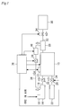
- FIG. 1 is a schematic diagram of a system configuration according to this embodiment.
- the system illustrated in Fig. 1 comprises an electrolysis device 10 in which CO gas and H 2 gas are generated simultaneously by electrolysis.
- Electrolysis device 10 is a device for electrolyzation equipped with a thermal control device 12 for controlling the internal temperature of the electrolysis device 10 within a prescribed temperature range. Detailed configuration of the electrolysis device 10 will be described in the description of Fig. 2 .
- an electrolytic solution tank 14 filled with an electrolytic solution having a property of absorbing CO 2 is provided on the upstream of the electrolysis device 10.
- the electrolytic solution tank 14 comprises an air introduction device 16.
- the air introduction device 16 comprises a compressor (not shown) and is configured to blow air at prescribed pressure into the electrolytic solution in the electrolytic solution tank 14. This leads to maintain the CO 2 concentration of the electrolytic solution in the electrolytic solution tank 14 constant (e.g., CO 2 saturation) at all times.
- the electrolytic solution tank 14 is connected to the electrolysis device 10 through a flow path 18.
- liquid pump 20 is provided on the flow path 18, liquid pump 20 is provided.
- the liquid pump 20 is configured to supply the electrolytic solution stored in the electrolytic solution tank 14 into the flow path 18 at prescribed pressure.
- a water tank 22 filled with water is provided on the upstream of the electrolysis device 10.
- the water tank 22 is connected to the electrolysis device 10 through a flow path 24.
- liquid pump 26 is provided on the flow path 24, liquid pump 26 is provided.
- the liquid pump 26 is configured to supply the water stored in the water tank 22 into the flow path 24 at prescribed pressure.
- a gas-liquid separator 28 is provided on the downstream of the electrolysis device 10. As will hereinafter be described, CO, H 2 and H 2 O are generated in a cathode room of the electrolysis device 10. These products are discharged from the electrolysis device 10 in a mixed state with the electrolytic solution, and then pumped into the gas-liquid separator device 28, thereby the gas and the liquid are separated.
- a FT reaction device 30 which can synthesize HC from CO and H 2 is provided on the downstream of the gas-liquid separator device28.
- the FT reaction device 30 is connected to the gas-liquid separator device 28 through a flow path 32.
- a mixed gas valve 34 whose opening degree is configured to be controllable is provided on the flow path 32.
- the mixed gas valve 34 includes a solenoid valve etc., and its opening degree is controlled depending on control signals. By opening the mixed gas valve 34, the gas-liquid separator 28 and the FT reaction device 30 are connected each other and then a mixed gas consisting of CO and H 2 which was separated in the gas-liquid separator device 28 flows into the FT reaction device 30.
- the gas-liquid separator 28 is connected to the electrolytic solution tank 14 through a flow path 36.
- a condensation device 38 and a liquid pump 40 are provided on the flow path 36.
- the condensation device 38 comprises a heating device and a cooling device therein.
- the condensation device 38 is configured to heat the electrolytic solution so as to remove an amount of water equivalent to the generated water therefrom, and to cool the electrolytic solution to a temperature close to the temperature of the electrolytic solution in the FT reaction device 30 thereafter.
- the liquid pump 40 is configured to supply the cooled electrolytic solution into the flow path 36 at a prescribed pressure.
- the liquid pumps 20, 40 function as circulation pumps for circulating the electrolytic solution through the electrolytic solution tank 14, the electrolysis device 10, the gas-liquid separator device 28 and the condensation device 38.
- the system of this embodiment further comprises a control unit 70.
- the above-mentioned thermal control device 12 On the input side of the control unit 70, the above-mentioned thermal control device 12 is connected.
- the electrolysis device 10 On the output side of the control unit 70, the electrolysis device 10, the thermal control device 12, the air introduction device 16, the liquid pump 20, 26 and 40, the mixed gas valve 34 and the condensation device 38 are connected.
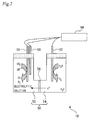
- Fig. 2 is a schematic diagram of the electrolysis device 10 in Fig. 1 .
- the electrolysis device 10 comprises a three-electrodes-type electrolytic cell 50.
- the electrolytic cell 50 comprises a cathode room 52 filled with the electrolytic solution, an anode room 54 filled with water, and a separating membrane 56 for separating the cathode room 52 and the anode room 54.
- the electrolytic solution tank 14 and the gas-liquid separator device 28 in Fig. 1 are connected.
- a working electrode (WE) 58 and a reference electrode (RE) 60 are provided in the cathode room 52.
- the WE 58 corresponds to a cathode of the electrolytic cell 50, and its body is made of a metal (e.g., Pt) which is less likely to reduce CO 2 during electrolysis.
- a CO 2 reduction catalyst which reduces CO 2 to CO selectively during the electrolysis is provided.
- CE 62 corresponds to an anode of the electrolytic cell 50, and its body is made of a metal (e.g., Au, Pt) which is not resolved during electrolysis.
- a commonly-used electrolyte (supporting electrolyte) may be added to the anode room 54.
- the separating membrane 56 has a function for transporting proton from the anode room 54 side to the cathode room 62 side, and is made of polyelectrolyte resin such as NAFION (registered trademark).
- the separating membrane 56 may be omitted.
- the electrolysis device 10 comprises a potentiostat 64.
- the potentiostat 64 is connected to the WE 58, RE 60, CE 62 and the control unit in Fig. 1 .
- the potentiostat 64 controls a current value which flows between the WE 58 and the CE 62 so as to hold a voltage between the WE 58 and the RE 60 at a set value.
- the reaction of the formula (A) occurs at the site where the CO 2 reduction catalyst on the WE 58 contacts with the electrolytic solution.
- the reaction of the formula (B) occurs at the site where the body of the WE 58 contacts with the electrolytic solution.
- the reaction of the formula (C) occurs at the site where the CE 62 contacts with water.
- HC can be manufactured as an alternative fuel for the fossil fuel. It is needless to say, here, that HC is preferably manufactured efficiently from a material stage.
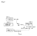
- a HC manufacturing process conducted by the system will be described with reference to Fig. 3 .
- the HC manufacturing process conducted by the system includes three steps (STEP 1 to STEP 3).
- STEP 1 is a CO 2 fixing step.
- STEP 1 is executed by controlling the air introduction device 16 so that air is blown into the electrolytic solution in the electrolytic solution tank 14 in Fig. 1 .
- STEP 2 is a mixed gas generating process.
- STEP 2 is executed by driving the liquid pumps 20, 26 and 40 while an electric current flow is carried between the WE 58 and the CE 62.
- STEP 3 is a FT synthesizing process. STEP 3 is executed so that HC is synthesized from the mixed gas in the FT reaction device 30.
- the manufactured HC through STEP 1 to STEP 3, for example, is supplied to an intake system of an internal combustion engine so as to be burned. CO 2 generated by the burning of the HC is emitted as exhaust gas into the atmosphere. Here, if it returns to STEP 1 again, the emitted CO 2 can be fixed into the electrolytic solution. And here, if an electric energy necessary to drive the present system is covered by natural energy (e.g., solar power, solar thermal power, wind power, tidal power, geothermal power and hydro power), a carbon-neutral fuel manufacture can be achieved and this will contribute to realize so-called sustainable mobility.
- natural energy e.g., solar power, solar thermal power, wind power, tidal power, geothermal power and hydro power
- Patent Document 1 describes two systems. Fig. 4 and Fig. 5 correspond to the flows conducted by the first system and the second system, respectively. For a detailed configuration of the first system or the second system, see Patent Document 1.
- the mixed gas generating process includes a CO generating process and a H 2 generating process, which are independent each other.
- CO 2 used to manufacture CO is generated in an anode room of an electrolysis device in which H 2 is generated.
- O 2 is also generated as well as CO 2 . Therefore, the CO 2 generated in the electrolysis device must be once absorbed, and then released so as to be supplied to the electrolytic cell, in order to generate CO.
- the CO generating process further includes a CO 2 absorbing process and a CO 2 releasing process, as shown in Fig. 4 .
- the mixed gas can be generated in the cathode of the electrolytic cell according to the flow conducted by the second system.
- CO 2 included in air, exhaust gas or the like is used as one for manufacturing CO.
- the CO 2 must be once absorbed, and then released so as to be supplied to the electrolytic cell. Therefore, the CO generating process includes a CO 2 absorbing process and a CO 2 releasing process, as shown in Fig. 5 .
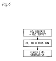
- the present system uses the electrolytic solution having a property of absorbing CO 2 . Therefore, the mixed gas can be generated directly from the electrolytic solution in which CO 2 has absorbed. In short, a CO 2 absorbing process is only needed to execute, as shown in Fig. 6 . Thus, the mixed gas generating process can be simplified as compared to one including the CO 2 releasing process, which is conducted by the first system or the second system. Further, the system construction can be downsized since a device for the CO 2 releasing process can be omitted.
- the electrolytic solution is a salt in the liquid state at room temperature (preferably, 0 centigrade degrees or higher) which is formed by a molecular makeup with cation site and anion site at ordinary temperatures and pressures (25 centigrade degrees, 1 atm).
- This electrolytic solution expresses the property of absorbing CO 2 by physical adsorption or chemical adsorption. Physical adsorption results from electrostatic interaction between the electrolytic solution and CO 2 .
- a salt being capable of expressing physical adsorption includes the one with fluorine atom on its anion site. Meanwhile, chemical adsorption results from a formation of a covalent bonding (an amide bond) between the electrolytic solution and CO 2 .
- a salt being capable of expressing chemical adsorption includes a primary amino group (-NH 2 ) and/or a secondary amino group (-NH-) on its cation site.
- a preferable salt used as the electrolytic solution in the system includes ionic liquid below.
- the ionic liquid is an organic salt being in molten state without crystallizing even at ordinary temperature, and is formed by a molecular makeup with cation site and anion site. Because of its quite low vapor pressure and its property of absorbing CO 2 , the ionic liquid is preferably used in the system.
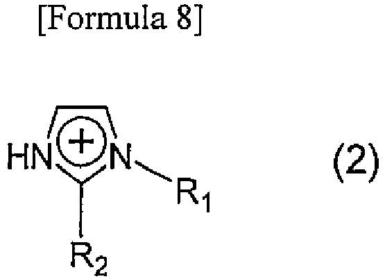
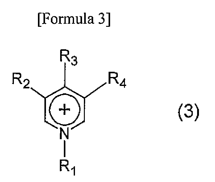
- the cation which is included in the ion liquid, corresponds to an imidazolium derivative expressed in the following formula (1) or (2), a pyridinium derivative expressed in the following formula (3), a pyrrolidinium derivative expressed in the following formula (4), an ammonium derivative expressed in the following formula (5) and a phosphonium derivative expressed in the following formula (6). More than one of these cations may be simultaneously used.
- R represents organic group which may have primary amino group and/or secondary amino group.
- the organic group preferably includes a hydrocarbon group and more preferably includes a C1-C20 alkyl group or arylalkyl group.
- R 1 represents organic group which may have primary amino group and/or secondary amino group, or hydrogen.
- R 2 represents organic group which may have primary amino group and/or secondary amino group.
- the organic group preferably includes a hydrocarbon group and more preferably includes a C1-C20 alkyl group or arylalkyl group.
- R 1 , R 2 , R 3 and R 4 may be the same or different each other.
- R 1 , R 2 , R 3 or R 4 represents organic group which may have primary amino group and/or secondary amino group, or hydrogen.
- the organic group preferably includes a hydrocarbon group and more preferably includes a C1-C20 alkyl group or arylalkyl group.
- R 1 and R 2 may be the same or different each other.
- R 1 or R 2 represents organic group which may have primary amino group and/or secondary amino group, or hydrogen.
- the organic group preferably includes a hydrocarbon group and more preferably includes a C1-C20 alkyl group or arylalkyl group.
- R 1 , R 2 , R 3 and R 4 may be the same or different each other.
- R 1 , R 2 , R 3 or R 4 represents organic group which may have primary amino group and/or secondary amino group, or hydrogen.
- the organic group preferably includes a hydrocarbon group and more preferably includes a C1-C20 alkyl group or arylalkyl group.
- R 1 , R 2 , R 3 and R 4 may be the same or different each other.
- R 1 , R 2 , R 3 or R 4 represents organic group which may have primary amino group and/or secondary amino group, or hydrogen.
- the organic group preferably includes a hydrocarbon group and more preferably includes a C1-C20 alkyl group or arylalkyl group.
- the electrolytic solution used in the system preferably has protonic conductivity as well as the property of absorbing CO 2 at the same time.
- a salt being capable of expressing protonic conductivity includes, for example, a protonic salt which consists of Br ⁇ nsted acid (HA) and base (B), (AH + B ⁇ [BH] [A]).
- the protonic salt specifically corresponds to the one that R 1 is hydrogen in the formulas (2) to (6).
- the anion which is included in the ion liquid, corresponds to PF 6 - , BF 4 - , CF 3 SO 3 - , CF 3 CF 2 SO 3 - , (CF 3 SO 2 ) 2 N - , (CF 3 CF 2 SO 2 ) 2 N - , (CF 3 CO) 2 N - , (CF 3 SO 2 )N(COCF 3 ) - , and FSO 2 NSO 2 F - . More than one of these anions may be simultaneously used.
- electrolysis can be performed with the above mentioned electrolytic solution. Therefore, the present system can simplify the mixed gas generating process as compared to the system conducting the CO 2 releasing process. And the system construction can be downsized since a device for the CO 2 releasing process can be omitted.
- the three-electrodes-type electrolytic cell 50 is used while the voltage between the WE 58 and the RE 60 is controlled by the potentiostat 64.
- a two-electrodes-type electrolytic cell in which the CE 62 also functions as the RE 60 can be used instead of the three-electrodes-type electrolytic cell 50. That is, any configurations can be applied as modified examples of the electrolysis device 10 of the embodiment as long as it can control the voltage applied between the WE 58 and the RE 60.
Landscapes
- Chemical & Material Sciences (AREA)
- Engineering & Computer Science (AREA)
- Chemical Kinetics & Catalysis (AREA)
- Organic Chemistry (AREA)
- Electrochemistry (AREA)
- Materials Engineering (AREA)
- Metallurgy (AREA)
- Inorganic Chemistry (AREA)
- Oil, Petroleum & Natural Gas (AREA)
- General Chemical & Material Sciences (AREA)
- Electrolytic Production Of Non-Metals, Compounds, Apparatuses Therefor (AREA)
- Production Of Liquid Hydrocarbon Mixture For Refining Petroleum (AREA)
Abstract
The present invention relates to a fuel manufacturing system and has an object to provide a fuel manufacturing system which can simplify in term of the system construction. An electrolytic solution having a property of absorbing CO2 is used in the system. Therefore, a mixed gas can be generated directly with the electrolytic solution in which CO2 has absorbed. In short, a CO2 absorbing process is only needed to execute, which is shown in Fig. 6 . Thus, the mixed gas generating process can be simplified as compared to a system including the CO2 releasing process (Fig. 4 , 5 ). And the system construction can be downsized since a device for the CO2 releasing process can be omitted.
Description
- The present invention relates to a fuel manufacturing system. More particularly, the present invention relates to a fuel manufacturing system for synthesizing the fuel from H2 and CO generated by electrolysis.
- Fossil fuels including petroleum, coal, natural gas and the like are used as a material for generating heat or electricity, and fuels for transportation so as to support the modern energy consumption society. However, such fossil fuels are exhaustible fuels and their reserves are limited. Thus, it is needless to say that preparation is needed for depletion of the fossil fuels. Moreover, emissions of CO2 caused by combustion of the fossil fuels into the atmosphere are known to be one of the factors which cause global warming. Thus, reduction of CO2 emissions has become a recent task.
- As a means for solving these problems, an alternative fuel using CO2 as a material has been examined. For example,
Patent Document 1 discloses a system for manufacturing hydrocarbon fuel (HC) using CO2 as a material. This system includes an electrolytic cell having an oxygen ion conductive film composed of a solid oxidized electrolyte as well as a cathode and an anode arranged on the both surfaces the electrolyte, respectively, so that HC is synthesized from a material gas generated by using this electrolytic cell. - A specific manufacturing method of HC in the above system is as follows. First, while electric power and heat are supplied to the electrolytic cell, CO2 gas and steam are supplied to the cathode, and carbon monoxide (CO) gas and hydrogen (H2) gas which become material gases are generated on this cathode, respectively. Subsequently, the generated material gas is collected from the electrolytic cell for reacting in a known manufacturing device which develops Fischer-Tropsch reaction (FT reaction) so as to obtain HC.
-
- Patent Document 1:
JP-A-2009-506213 - Patent Document 2:
JP-A-2010-053425 - Non-Patent document 1: Satoshi Kaneco et al., "Electrochemical reduction of CO2 on Au in KOH + methanol at low temperature" Journal of Electroanalytical Chemistry 441 (1998) 215-220
Non-Patent document 2: Guoying Zhao et al. "Electrochemical reduction of supercritical carbon dioxide in ionic liquid 1-n-butyl-3-methylimidazolium hexafluorophosphate" J. of Supercritical Fluids 32 (2004) 287-291 - In the system of the above-described
Patent Document 1, air, combustion gas or aerobic gas are supplied to the electrolytic cell after passing through a gas separator and separating CO2 gas contained in the gas. In short, CO2 gas is separated by the gas separator. Here, in order to separate CO2 gas from other gas, the gas separator should have (i) a function to absorb any gases other than CO2 gas, or (ii) a function to absorb only CO2 gas. Since there are so many gases other than CO2 gas, the function of the above-described (i) is not realistic. Thus, the gas separator should have the function of the above-described (ii). - Then, in order to supply CO2 gas to the above-described electrolytic cell, the absorbed CO2 in the gas separator needs to be released again. In order to release the absorbed CO2 gas again, however, a device for the release or the like would be needed. Therefore, the system of the above-described
Patent Document 1 leads to problems that the gas separator construction becomes complex and the system construction becomes large. - The present invention was made in order to solve the above mentioned problem. It is an object of the present invention to provide a fuel manufacturing system which can simplify the system construction.
- To achieve the above-described purpose, a first aspect of the present invention is a fuel manufacturing system, comprising:
- an electrolysis device for generating carbon monoxide and hydrogen by electrolyzing carbon dioxide and water respectively; and
- a fuel synthesizing device for synthesizing hydrocarbon fuel, by occurring Fischer-Tropsch reaction, from carbon monoxide and hydrogen which are generated in the electrolysis device, wherein
- the electrolysis device comprises electrolytic solution having a property of absorbing carbon dioxide therein.
- A second aspect of the present invention is the fuel manufacturing system according to the first aspect of the present invention, wherein
said electrolytic solution has protonic conductivity. - A third aspect of the present invention is the fuel manufacturing system according to the first or the second aspect of the present invention, wherein
ionic liquid is used as said electrolytic solution. - A forth aspect of the present invention is the fuel manufacturing system according to the third aspect of the present invention, wherein
said ionic liquid includes at least one type of cation expressed in the following formulas (1) to (6) and at least one type of anion expressed as PF6 -, BF4 -, CF3SO3 -, CF3CF2SO3 -, (CF3SO2)2N-, (CF3CF2SO2)2N-, (CF3CO)2N-, (CF3SO2)N(COCF3)-, and FSO2NSO2F-. -

-

-


-

-

-

- A fifth aspect of the present invention is the fuel manufacturing system according to any one of the first aspect to the forth aspect of the present invention, wherein
said electrolysis device comprises a electrolytic cell comprising a cathode room filled with said electrolytic solution, an anode room filled with water, a proton-conducting separating membrane for separating said anode room and said cathode room. - According to the first aspect of the present invention, electrolysis can be performed with the electrolytic solution having a property of absorbing CO2. Therefore, equipments necessary for separating CO2 gas in the air or the like from other gas and releasing again can be omitted. And thus, the system construction can be downsized.
- According to the second aspect of the present invention, the use of the electrolytic solution having protonic conductivity makes it possible for proton to enhance its mobility, and thus the generation of hydrogen can be encouraged in electrolysis. According to the third or the forth aspect of the present invention, since the ionic liquid is used as the electrolytic solution, the ionic liquid's nature of liquid salt at ordinary temperature can be used. Therefore, CO and H2 can be easily generated by electrolysis under room temperature condition.
- According to the fifth aspect of the present invention, the proton-conducting separating membrane makes it possible to prevent the electrolytic solution in the cathode room and water in the anode room from mixing. When the proton-conducting separating membrane can prevent the mixing, the CO2 concentration or proton concentration in the cathode room, or the control of the water volume in the anode room can be controlled easily. Therefore, a ratio of CO to H2 generated in the cathode room can be easily adjusted.
-
-
Fig. 1 is a schematic diagram of a system configuration according to an embodiment. -
Fig. 2 is a schematic diagram of anelectrolysis device 10 used in the embodiment. -
Fig. 3 is a diagram for explaining a brief overview of a HC synthesizing process with the system of the embodiment. -
Fig.4 is a diagram for explaining a flow of a mixed gas generating process for a comparison purpose with this embodiment. -
Fig.5 is a diagram for explaining a flow of a mixed gas generating process for a comparison purpose with this embodiment. -
Fig.6 is a diagram for explaining a flow of a mixed gas generating process of this embodiment. - An embodiment of the present invention will be described below with reference to
Figs. 1 to 5 . In this embodiment, a system for manufacturing a fuel to be supplied to an internal combustion by using natural energy will be explained as an example.Fig. 1 is a schematic diagram of a system configuration according to this embodiment. The system illustrated inFig. 1 comprises anelectrolysis device 10 in which CO gas and H2 gas are generated simultaneously by electrolysis.Electrolysis device 10 is a device for electrolyzation equipped with athermal control device 12 for controlling the internal temperature of theelectrolysis device 10 within a prescribed temperature range. Detailed configuration of theelectrolysis device 10 will be described in the description ofFig. 2 . - On the upstream of the
electrolysis device 10, anelectrolytic solution tank 14 filled with an electrolytic solution having a property of absorbing CO2 is provided. Theelectrolytic solution tank 14 comprises anair introduction device 16. Theair introduction device 16 comprises a compressor (not shown) and is configured to blow air at prescribed pressure into the electrolytic solution in theelectrolytic solution tank 14. This leads to maintain the CO2 concentration of the electrolytic solution in theelectrolytic solution tank 14 constant (e.g., CO2 saturation) at all times. Theelectrolytic solution tank 14 is connected to theelectrolysis device 10 through aflow path 18. On theflow path 18,liquid pump 20 is provided. Theliquid pump 20 is configured to supply the electrolytic solution stored in theelectrolytic solution tank 14 into theflow path 18 at prescribed pressure. - On the upstream of the
electrolysis device 10, awater tank 22 filled with water is provided. Thewater tank 22 is connected to theelectrolysis device 10 through aflow path 24. On theflow path 24,liquid pump 26 is provided. Theliquid pump 26 is configured to supply the water stored in thewater tank 22 into theflow path 24 at prescribed pressure. - Meanwhile, a gas-
liquid separator 28 is provided on the downstream of theelectrolysis device 10. As will hereinafter be described, CO, H2 and H2O are generated in a cathode room of theelectrolysis device 10. These products are discharged from theelectrolysis device 10 in a mixed state with the electrolytic solution, and then pumped into the gas-liquid separator device 28, thereby the gas and the liquid are separated. - On the downstream of the gas-liquid separator device28, a
FT reaction device 30 which can synthesize HC from CO and H2 is provided. TheFT reaction device 30 is connected to the gas-liquid separator device 28 through aflow path 32. On theflow path 32, amixed gas valve 34 whose opening degree is configured to be controllable is provided. Themixed gas valve 34 includes a solenoid valve etc., and its opening degree is controlled depending on control signals. By opening themixed gas valve 34, the gas-liquid separator 28 and theFT reaction device 30 are connected each other and then a mixed gas consisting of CO and H2 which was separated in the gas-liquid separator device 28 flows into theFT reaction device 30. - The gas-
liquid separator 28 is connected to theelectrolytic solution tank 14 through aflow path 36. On theflow path 36, acondensation device 38 and aliquid pump 40 are provided. Thecondensation device 38 comprises a heating device and a cooling device therein. Thecondensation device 38 is configured to heat the electrolytic solution so as to remove an amount of water equivalent to the generated water therefrom, and to cool the electrolytic solution to a temperature close to the temperature of the electrolytic solution in theFT reaction device 30 thereafter. Theliquid pump 40 is configured to supply the cooled electrolytic solution into theflow path 36 at a prescribed pressure. The liquid pumps 20, 40 function as circulation pumps for circulating the electrolytic solution through theelectrolytic solution tank 14, theelectrolysis device 10, the gas-liquid separator device 28 and thecondensation device 38. - The system of this embodiment further comprises a
control unit 70. On the input side of thecontrol unit 70, the above-mentionedthermal control device 12 is connected. On the output side of thecontrol unit 70, theelectrolysis device 10, thethermal control device 12, theair introduction device 16, theliquid pump mixed gas valve 34 and thecondensation device 38 are connected. - Next, the configuration of the
electrolysis device 10 will be described in detail with reference toFig. 2. Fig. 2 is a schematic diagram of theelectrolysis device 10 inFig. 1 . Theelectrolysis device 10 comprises a three-electrodes-typeelectrolytic cell 50. Theelectrolytic cell 50 comprises acathode room 52 filled with the electrolytic solution, ananode room 54 filled with water, and a separatingmembrane 56 for separating thecathode room 52 and theanode room 54. - To the
cathode room 52, theelectrolytic solution tank 14 and the gas-liquid separator device 28 inFig. 1 are connected. In thecathode room 52, a working electrode (WE) 58 and a reference electrode (RE) 60 are provided. TheWE 58 corresponds to a cathode of theelectrolytic cell 50, and its body is made of a metal (e.g., Pt) which is less likely to reduce CO2 during electrolysis. On a part of this body's surface, a CO2 reduction catalyst which reduces CO2 to CO selectively during the electrolysis is provided. - To the
anode room 54, thewater tank 22 inFig. 1 is connected. In theanode room 54, a counter electrode (CE) 62 is provided.CE 62 corresponds to an anode of theelectrolytic cell 50, and its body is made of a metal (e.g., Au, Pt) which is not resolved during electrolysis. A commonly-used electrolyte (supporting electrolyte) may be added to theanode room 54. - The separating
membrane 56 has a function for transporting proton from theanode room 54 side to thecathode room 62 side, and is made of polyelectrolyte resin such as NAFION (registered trademark). The separatingmembrane 56 may be omitted. - The
electrolysis device 10 comprises apotentiostat 64. Thepotentiostat 64 is connected to theWE 58,RE 60,CE 62 and the control unit inFig. 1 . Thepotentiostat 64 controls a current value which flows between theWE 58 and theCE 62 so as to hold a voltage between theWE 58 and theRE 60 at a set value. - Here, electrolysis conducted by the
electrolysis device 10 will be described. When thepotentiostat 64 is controlled so that an electric current flow is carried between theWE 58 and theCE 62, electrochemical reactions of the following formulas (A) to (C) occur at theWE 58 and the CE62:
WE 58: CO2 + 2H+ + 2e- → CO + H2O (A)
2H+ + 2e- → H2 (B)
CE 62: 2H2O → O2 + 4H+ + 4e- (C)
- The reaction of the formula (A) occurs at the site where the CO2 reduction catalyst on the
WE 58 contacts with the electrolytic solution. The reaction of the formula (B) occurs at the site where the body of theWE 58 contacts with the electrolytic solution. The reaction of the formula (C) occurs at the site where theCE 62 contacts with water. - When water is supplied to the
anode room 54 by driving theliquid pump 26 while an electric current flow is being carried between theWE 58 and theCE 62, proton can be continuously generated on the CE 62 (the above-described formula (C)). On this occasion, additionally, when the electrolytic solution is supplied to thecathode room 52 by driving theliquid pump 20, CO2 and proton can be supplied to thecathode room 52 continuously. Therefore, according to the system, CO and H2 can be continuously generated on the WE 58 (the above-described formula (A) and (B)). Since CO and H2 have low solubility in the electrolytic solution, almost all of the generated CO and H2 are present in a gaseous state. - When the generated CO and H2 are collected so as to occur the FT reaction, HC can be manufactured as an alternative fuel for the fossil fuel. It is needless to say, here, that HC is preferably manufactured efficiently from a material stage. In this connection, it has been known that high energy efficiency of the FT reaction is achieved when a mixing ratio between CO and H2 is set to CO / H2 = 1/2. In this embodiment, considering the energy efficiency, a voltage between the
WE 58 and theRE 60 is set so that a ratio in a generation stage is CO / H2 = 1/2. - A HC manufacturing process conducted by the system will be described with reference to
Fig. 3 . As shown inFig. 3 , the HC manufacturing process conducted by the system includes three steps (STEP 1 to STEP 3). -
STEP 1 is a CO2 fixing step.STEP 1 is executed by controlling theair introduction device 16 so that air is blown into the electrolytic solution in theelectrolytic solution tank 14 inFig. 1 .STEP 2 is a mixed gas generating process.STEP 2 is executed by driving the liquid pumps 20, 26 and 40 while an electric current flow is carried between theWE 58 and theCE 62.STEP 3 is a FT synthesizing process.STEP 3 is executed so that HC is synthesized from the mixed gas in theFT reaction device 30. - The manufactured HC through
STEP 1 toSTEP 3, for example, is supplied to an intake system of an internal combustion engine so as to be burned. CO2 generated by the burning of the HC is emitted as exhaust gas into the atmosphere. Here, if it returns to STEP 1 again, the emitted CO2 can be fixed into the electrolytic solution. And here, if an electric energy necessary to drive the present system is covered by natural energy (e.g., solar power, solar thermal power, wind power, tidal power, geothermal power and hydro power), a carbon-neutral fuel manufacture can be achieved and this will contribute to realize so-called sustainable mobility. - As mentioned previously, the electrolytic solution having a property of absorbing CO2 is used in the system. This reason will be described with reference to
Figs 4 to 6 . First, a flow of a mixed gas generating process conducted in a case where the system in the above-described Patent Document 1 (JP-A-2009-506213 Figs. 4 to 5 .Patent Document 1 describes two systems.Fig. 4 andFig. 5 correspond to the flows conducted by the first system and the second system, respectively. For a detailed configuration of the first system or the second system, seePatent Document 1. - Through the flow conducted by the first system, CO is generated in an electrolytic cell whereas H2 is generated in a cathode room. So, as shown in
Fig. 4 , the mixed gas generating process includes a CO generating process and a H2 generating process, which are independent each other. CO2 used to manufacture CO is generated in an anode room of an electrolysis device in which H2 is generated. In this anode room, O2 is also generated as well as CO2. Therefore, the CO2 generated in the electrolysis device must be once absorbed, and then released so as to be supplied to the electrolytic cell, in order to generate CO. Thus, the CO generating process further includes a CO2 absorbing process and a CO2 releasing process, as shown inFig. 4 . - Meanwhile, the mixed gas can be generated in the cathode of the electrolytic cell according to the flow conducted by the second system. However, CO2 included in air, exhaust gas or the like is used as one for manufacturing CO. Thus, the CO2 must be once absorbed, and then released so as to be supplied to the electrolytic cell. Therefore, the CO generating process includes a CO2 absorbing process and a CO2 releasing process, as shown in
Fig. 5 . - In this regard, the present system uses the electrolytic solution having a property of absorbing CO2. Therefore, the mixed gas can be generated directly from the electrolytic solution in which CO2 has absorbed. In short, a CO2 absorbing process is only needed to execute, as shown in
Fig. 6 . Thus, the mixed gas generating process can be simplified as compared to one including the CO2 releasing process, which is conducted by the first system or the second system. Further, the system construction can be downsized since a device for the CO2 releasing process can be omitted. - Next, the electrolytic solution used in the system will be described. The electrolytic solution is a salt in the liquid state at room temperature (preferably, 0 centigrade degrees or higher) which is formed by a molecular makeup with cation site and anion site at ordinary temperatures and pressures (25 centigrade degrees, 1 atm). This electrolytic solution expresses the property of absorbing CO2 by physical adsorption or chemical adsorption. Physical adsorption results from electrostatic interaction between the electrolytic solution and CO2. A salt being capable of expressing physical adsorption includes the one with fluorine atom on its anion site. Meanwhile, chemical adsorption results from a formation of a covalent bonding (an amide bond) between the electrolytic solution and CO2. A salt being capable of expressing chemical adsorption includes a primary amino group (-NH2) and/or a secondary amino group (-NH-) on its cation site.
- A preferable salt used as the electrolytic solution in the system includes ionic liquid below. The ionic liquid is an organic salt being in molten state without crystallizing even at ordinary temperature, and is formed by a molecular makeup with cation site and anion site. Because of its quite low vapor pressure and its property of absorbing CO2, the ionic liquid is preferably used in the system.
- The cation, which is included in the ion liquid, corresponds to an imidazolium derivative expressed in the following formula (1) or (2), a pyridinium derivative expressed in the following formula (3), a pyrrolidinium derivative expressed in the following formula (4), an ammonium derivative expressed in the following formula (5) and a phosphonium derivative expressed in the following formula (6). More than one of these cations may be simultaneously used.
-


-
-

-

-

-

- The electrolytic solution used in the system preferably has protonic conductivity as well as the property of absorbing CO2 at the same time. By having protonic conductivity, the mobility of proton in the
cathode room 54 can be enhanced more and thus, the generation amount of H2 at theWE 58 can be increased. A salt being capable of expressing protonic conductivity includes, for example, a protonic salt which consists of Brønsted acid (HA) and base (B), (AH + B → [BH] [A]). The protonic salt specifically corresponds to the one that R1 is hydrogen in the formulas (2) to (6). - The anion, which is included in the ion liquid, corresponds to PF6 -, BF4 -, CF3SO3 -, CF3CF2SO3 -, (CF3SO2)2N-, (CF3CF2SO2)2N-, (CF3CO)2N-, (CF3SO2)N(COCF3)-, and FSO2NSO2F-. More than one of these anions may be simultaneously used.
- Thus, according to the system of this embodiment, electrolysis can be performed with the above mentioned electrolytic solution. Therefore, the present system can simplify the mixed gas generating process as compared to the system conducting the CO2 releasing process. And the system construction can be downsized since a device for the CO2 releasing process can be omitted.
- In this embodiment, the three-electrodes-type
electrolytic cell 50 is used while the voltage between theWE 58 and theRE 60 is controlled by thepotentiostat 64. However, a two-electrodes-type electrolytic cell in which theCE 62 also functions as theRE 60 can be used instead of the three-electrodes-typeelectrolytic cell 50. That is, any configurations can be applied as modified examples of theelectrolysis device 10 of the embodiment as long as it can control the voltage applied between theWE 58 and theRE 60. -
- 10
- electrolysis device
- 12
- thermal control device
- 14
- electrolytic solution tank
- 16
- air introduction device
- 18, 24, 32, 36
- flow path
- 20, 26, 40
- liquid pump
- 22
- water tank
- 28
- gas-liquid separator
- 30
- FT reaction device
- 34
- mixed gas valve
- 38
- condensation device
- 50
- electrolytic cell
- 52
- cathode room
- 54
- anode room
- 56
- separating membrane
- 58
- working electrode
- 60
- reference electrode
- 62
- counter electrode
- 64
- potentiostat
- 70
- control unit
Claims (5)
- A fuel manufacturing system, comprising:an electrolysis device for generating carbon monoxide and hydrogen by electrolyzing carbon dioxide and water, respectively; anda fuel synthesizing device for synthesizing hydrocarbon fuel, by occurring Fischer-Tropsch reaction, from carbon monoxide and hydrogen which are generated in the electrolysis device, whereinthe electrolysis device comprises electrolytic solution having a property of absorbing carbon dioxide therein.
- The fuel manufacturing system according to claim 1, wherein
said electrolytic solution has protonic conductivity. - The fuel manufacturing system according to claim 1 or 2, wherein
ionic liquid is used as said electrolytic solution. - The fuel manufacturing system according to claim 3, wherein
said ionic liquid includes at least one type of cation expressed in the following formulas (1) to (6) and at least one type of anion expressed as PF6 -, BF4 -, CF3SO3 -, CF3CF2SO3 -, (CF3SO2)2N-, (CF3CF2SO2)2N-, (CF3CO)2N-, (CF3SO2)N(COCF3)-, and FSO2NSO2F-.




- The fuel manufacturing system according to any one of claims 1 to 4, wherein said electrolysis device comprises a electrolytic cell comprising a cathode room filled with said electrolytic solution, an anode room filled with water, a proton-conducting separating membrane for separating said anode room and said cathode room.
Applications Claiming Priority (1)
| Application Number | Priority Date | Filing Date | Title |
|---|---|---|---|
| PCT/JP2010/072026 WO2012077198A1 (en) | 2010-12-08 | 2010-12-08 | Fuel production system |
Publications (1)
| Publication Number | Publication Date |
|---|---|
| EP2650344A1 true EP2650344A1 (en) | 2013-10-16 |
Family
ID=46206717
Family Applications (1)
| Application Number | Title | Priority Date | Filing Date |
|---|---|---|---|
| EP10860422.4A Withdrawn EP2650344A1 (en) | 2010-12-08 | 2010-12-08 | Fuel production system |
Country Status (5)
| Country | Link |
|---|---|
| US (1) | US20130287636A1 (en) |
| EP (1) | EP2650344A1 (en) |
| JP (1) | JPWO2012077198A1 (en) |
| CN (1) | CN103249812A (en) |
| WO (1) | WO2012077198A1 (en) |
Families Citing this family (22)
| Publication number | Priority date | Publication date | Assignee | Title |
|---|---|---|---|---|
| RS56020B1 (en) * | 2009-11-04 | 2017-09-29 | Ffgf Ltd | HYDROCARBON PRODUCTION |
| US9500362B2 (en) | 2010-01-21 | 2016-11-22 | Powerdyne, Inc. | Generating steam from carbonaceous material |
| WO2012158797A1 (en) | 2011-05-16 | 2012-11-22 | Powerdyne, Inc. | Steam generation system |
| EP2892643A4 (en) | 2012-09-05 | 2016-05-11 | Powerdyne Inc | Methods for generating hydrogen gas using plasma sources |
| EP2900353A4 (en) | 2012-09-05 | 2016-05-18 | Powerdyne Inc | Method for sequestering heavy metal particulates using h2o, co2, o2, and a source of particulates |
| WO2014039719A1 (en) | 2012-09-05 | 2014-03-13 | Powerdyne, Inc. | Fuel generation using high-voltage electric fields methods |
| KR20150053781A (en) | 2012-09-05 | 2015-05-18 | 파워다인, 인코포레이티드 | Fuel generation using high-voltage electric fields methods |
| KR20150053943A (en) | 2012-09-05 | 2015-05-19 | 파워다인, 인코포레이티드 | Fuel generation using high-voltage electric fields methods |
| KR101581263B1 (en) * | 2012-09-05 | 2015-12-31 | 파워다인, 인코포레이티드 | System for generating fuel materials using fischer-tropsch catalysts and plasma sources |
| EP2904221A4 (en) | 2012-09-05 | 2016-05-18 | Powerdyne Inc | Methods for power generation from h2o, co2, o2 and a carbon feed stock |
| JP6034151B2 (en) * | 2012-11-20 | 2016-11-30 | 株式会社東芝 | Photochemical reactor |
| JP6067344B2 (en) * | 2012-11-20 | 2017-01-25 | 株式会社東芝 | Photochemical reaction system |
| WO2014165162A1 (en) | 2013-03-12 | 2014-10-09 | Powerdyne, Inc. | Systems and methods for producing fuel from parallel processed syngas |
| DE102013224077A1 (en) * | 2013-11-26 | 2015-05-28 | Siemens Aktiengesellschaft | Proton sponges as an additive to electrolytes for photocatalytic and electrochemical CO2 reduction |
| DE102013224202A1 (en) * | 2013-11-27 | 2015-05-28 | Siemens Aktiengesellschaft | Electrolytic cell and process for the production of chemical products by means of an electrolytic cell |
| US20170268118A1 (en) | 2016-03-18 | 2017-09-21 | Kabushiki Kaisha Toshiba | Electrochemical reaction device |
| JP6744242B2 (en) | 2017-03-10 | 2020-08-19 | 株式会社東芝 | Chemical reaction system |
| DE102017212278A1 (en) * | 2017-07-18 | 2019-01-24 | Siemens Aktiengesellschaft | CO2 electrolyser |
| US11105006B2 (en) | 2018-03-22 | 2021-08-31 | Sekisui Chemical Co., Ltd. | Carbon dioxide reduction apparatus and method of producing organic compound |
| US11390955B2 (en) | 2019-08-07 | 2022-07-19 | Sekisui Chemical Co., Ltd. | Electrochemical cell, electrochemical system, and method of producing carbonate compound |
| KR20230134127A (en) * | 2021-01-27 | 2023-09-20 | 토프쉐 에이/에스 | Production of synthesis gas from CO2 and steam for fuel synthesis |
| JPWO2024135202A1 (en) * | 2022-12-22 | 2024-06-27 |
Family Cites Families (3)
| Publication number | Priority date | Publication date | Assignee | Title |
|---|---|---|---|---|
| EP1938406A4 (en) | 2005-08-25 | 2010-04-21 | Ceramatec Inc | Electrochemical cell for the production of synthesis gas using atmospheric air and water |
| CN101250711B (en) * | 2008-03-27 | 2010-11-10 | 昆明理工大学 | Electrochemical reduction method and device for carbon dioxide in ionic liquid |
| JP5557434B2 (en) * | 2008-08-29 | 2014-07-23 | 学校法人同志社 | Method for fixing carbon in carbon dioxide |
-
2010
- 2010-12-08 WO PCT/JP2010/072026 patent/WO2012077198A1/en not_active Ceased
- 2010-12-08 EP EP10860422.4A patent/EP2650344A1/en not_active Withdrawn
- 2010-12-08 JP JP2012547629A patent/JPWO2012077198A1/en active Pending
- 2010-12-08 CN CN2010800705568A patent/CN103249812A/en active Pending
- 2010-12-08 US US13/879,727 patent/US20130287636A1/en not_active Abandoned
Non-Patent Citations (1)
| Title |
|---|
| See references of WO2012077198A1 * |
Also Published As
| Publication number | Publication date |
|---|---|
| WO2012077198A1 (en) | 2012-06-14 |
| CN103249812A (en) | 2013-08-14 |
| JPWO2012077198A1 (en) | 2014-05-19 |
| US20130287636A1 (en) | 2013-10-31 |
Similar Documents
| Publication | Publication Date | Title |
|---|---|---|
| EP2650344A1 (en) | Fuel production system | |
| Chisholm et al. | Hydrogen from water electrolysis | |
| De Saint Jean et al. | Parametric study of an efficient renewable power-to-substitute-natural-gas process including high-temperature steam electrolysis | |
| CN105297067B (en) | A kind of multicell diaphragm electrolysis method and apparatus by carbon dioxide electroreduction for carbon monoxide | |
| CA2579133A1 (en) | Method for producing fuel from captured carbon dioxide | |
| Ayers et al. | Efficient generation of high energy density fuel from water | |
| Gutiérrez-Guerra et al. | Electrochemical reforming vs. catalytic reforming of ethanol: A process energy analysis for hydrogen production | |
| CA2742755A1 (en) | Methods and apparatus of electrochemical production of carbon monoxide, and uses thereof | |
| Milewski et al. | Concept of a solid oxide electrolysis-molten carbonate fuel cell hybrid system to support a power-to-gas installation | |
| JP2015054994A (en) | Solid polymer electrolysis method and system. | |
| US9954239B2 (en) | Solid polymer power generation or electrolysis method and system | |
| Siddiqui et al. | Experimental investigation of an integrated solar powered clean hydrogen to ammonia synthesis system | |
| ITFI20090155A1 (en) | SYSTEM TO ENRICH HYDROGEN THE POWER OF INTERNAL COMBUSTION ENGINES POWERED IN AMMONIA DURING THE STARTING PHASE AND DURING THE RUN. | |
| Pozio et al. | Development perspectives on low-temperature electrolysis | |
| Azzam et al. | Design and analysis of an alkaline fuel cell | |
| Boretti | Reviewing the progress toward an ammonia energy storage ecosystem | |
| Osman et al. | Optimizing the production of ammonia as an energy carrier in the UAE | |
| CN205329170U (en) | Multi -chambered diaphragm electrolysis device that is carbon dioxide electroreduction carbon monoxide | |
| KR20240074838A (en) | Combined hydrogen and electricity production from aqueous ammonia feed | |
| KR20160008114A (en) | Power generation systems and methods utilizing cascaded fuel cells | |
| Migliardini et al. | Hydrogen and proton exchange membrane fuel cells for clean road transportation | |
| Reichelt et al. | Co-electrolysis | |
| Nikolov et al. | Hydrogen Production Technologies–A comparative overview and future developments | |
| He et al. | Photothermally enhanced electrocatalytic water splitting for hydrogen production | |
| Qian et al. | Three-dimensional modeling and analysis of polymer electrolyte membrane SO2-depolarized electrolyzer |
Legal Events
| Date | Code | Title | Description |
|---|---|---|---|
| PUAI | Public reference made under article 153(3) epc to a published international application that has entered the european phase |
Free format text: ORIGINAL CODE: 0009012 |
|
| 17P | Request for examination filed |
Effective date: 20130417 |
|
| AK | Designated contracting states |
Kind code of ref document: A1 Designated state(s): AL AT BE BG CH CY CZ DE DK EE ES FI FR GB GR HR HU IE IS IT LI LT LU LV MC MK MT NL NO PL PT RO RS SE SI SK SM TR |
|
| DAX | Request for extension of the european patent (deleted) | ||
| STAA | Information on the status of an ep patent application or granted ep patent |
Free format text: STATUS: THE APPLICATION IS DEEMED TO BE WITHDRAWN |
|
| 18D | Application deemed to be withdrawn |
Effective date: 20150701 |