EP2650211A2 - Thermal insulation support - Google Patents
Thermal insulation support Download PDFInfo
- Publication number
- EP2650211A2 EP2650211A2 EP13162163.3A EP13162163A EP2650211A2 EP 2650211 A2 EP2650211 A2 EP 2650211A2 EP 13162163 A EP13162163 A EP 13162163A EP 2650211 A2 EP2650211 A2 EP 2650211A2
- Authority
- EP
- European Patent Office
- Prior art keywords
- edge portion
- flange
- heat shield
- thermal insulation
- shield assembly
- Prior art date
- Legal status (The legal status is an assumption and is not a legal conclusion. Google has not performed a legal analysis and makes no representation as to the accuracy of the status listed.)
- Granted
Links
Images


Classifications
-
- B—PERFORMING OPERATIONS; TRANSPORTING
- B64—AIRCRAFT; AVIATION; COSMONAUTICS
- B64C—AEROPLANES; HELICOPTERS
- B64C7/00—Structures or fairings not otherwise provided for
- B64C7/02—Nacelles
-
- B—PERFORMING OPERATIONS; TRANSPORTING
- B64—AIRCRAFT; AVIATION; COSMONAUTICS
- B64C—AEROPLANES; HELICOPTERS
- B64C1/00—Fuselages; Constructional features common to fuselages, wings, stabilising surfaces or the like
- B64C1/40—Sound or heat insulation, e.g. using insulation blankets
-
- B—PERFORMING OPERATIONS; TRANSPORTING
- B64—AIRCRAFT; AVIATION; COSMONAUTICS
- B64D—EQUIPMENT FOR FITTING IN OR TO AIRCRAFT; FLIGHT SUITS; PARACHUTES; ARRANGEMENT OR MOUNTING OF POWER PLANTS OR PROPULSION TRANSMISSIONS IN AIRCRAFT
- B64D27/00—Arrangement or mounting of power plants in aircraft; Aircraft characterised by the type or position of power plants
- B64D27/02—Aircraft characterised by the type or position of power plants
- B64D27/16—Aircraft characterised by the type or position of power plants of jet type
- B64D27/18—Aircraft characterised by the type or position of power plants of jet type within, or attached to, wings
-
- B—PERFORMING OPERATIONS; TRANSPORTING
- B64—AIRCRAFT; AVIATION; COSMONAUTICS
- B64D—EQUIPMENT FOR FITTING IN OR TO AIRCRAFT; FLIGHT SUITS; PARACHUTES; ARRANGEMENT OR MOUNTING OF POWER PLANTS OR PROPULSION TRANSMISSIONS IN AIRCRAFT
- B64D29/00—Power-plant nacelles, fairings or cowlings
-
- Y—GENERAL TAGGING OF NEW TECHNOLOGICAL DEVELOPMENTS; GENERAL TAGGING OF CROSS-SECTIONAL TECHNOLOGIES SPANNING OVER SEVERAL SECTIONS OF THE IPC; TECHNICAL SUBJECTS COVERED BY FORMER USPC CROSS-REFERENCE ART COLLECTIONS [XRACs] AND DIGESTS
- Y10—TECHNICAL SUBJECTS COVERED BY FORMER USPC
- Y10T—TECHNICAL SUBJECTS COVERED BY FORMER US CLASSIFICATION
- Y10T29/00—Metal working
- Y10T29/49—Method of mechanical manufacture
- Y10T29/49826—Assembling or joining
-
- Y—GENERAL TAGGING OF NEW TECHNOLOGICAL DEVELOPMENTS; GENERAL TAGGING OF CROSS-SECTIONAL TECHNOLOGIES SPANNING OVER SEVERAL SECTIONS OF THE IPC; TECHNICAL SUBJECTS COVERED BY FORMER USPC CROSS-REFERENCE ART COLLECTIONS [XRACs] AND DIGESTS
- Y10—TECHNICAL SUBJECTS COVERED BY FORMER USPC
- Y10T—TECHNICAL SUBJECTS COVERED BY FORMER US CLASSIFICATION
- Y10T428/00—Stock material or miscellaneous articles
- Y10T428/24—Structurally defined web or sheet [e.g., overall dimension, etc.]
- Y10T428/24479—Structurally defined web or sheet [e.g., overall dimension, etc.] including variation in thickness
- Y10T428/24612—Composite web or sheet
Definitions
- the present disclosure relates generally to insulation systems and, more particularly, to a support for use in supporting a thermal insulation block within a heat shield.
- At least some known heat shield assemblies are positioned above an engine exhaust to facilitate reducing heat transfer. For example, due to its proximity to the engine exhaust, the lower skin of at least some known heat shield assemblies may be exposed to relatively high temperatures.
- at least some known engines include insulation positioned within the heat shield assembly directly against the lower skin.
- at least some known heat shield assemblies use a thicker insulation. Increasing a thickness of the insulation, however, may increase a weight associated with the insulation and/or heat shield assembly.
- a method for use in installing an insulation support within a heat shield assembly.
- the method includes coupling a first flange to a first wall of the heat shield assembly.
- the first flange extends a first distance from a first edge portion of a body.
- the first edge portion extends generally along a longitudinal axis of the body.
- a second flange is coupled to a second wall of the heat shield assembly.
- the second flange extends a second distance from a second edge portion of the body.
- the second edge portion extends generally along the longitudinal axis of the body.
- thermo insulation support is substantially seamless.
- thermal insulation support at least partially from a resilient material that enables at least one of the first flange and the second flange to deflect from a base position.
- a thermal insulation support for use within a heat shield assembly.
- the thermal insulation support includes a body including a first edge portion and a second edge portion extending generally along a longitudinal axis of the body.
- a first flange extends a first distance from the first edge portion of the body.
- the first flange is coupleable to a first wall of the heat shield assembly.
- a second flange extends a second distance from the second edge portion of the body.
- the second flange is coupleable to a second wall of the heat shield assembly.
- the body has a wave-shaped configuration extending between said first edge portion and said second edge portion, the wave-shaped configuration including a plurality of waves extending between said first edge portion and said second edge portion, said plurality of waves spaced along the longitudinal axis in a staggered configuration.
- At least one of said first edge portion and said second edge portion comprises a curved heel.
- At least one of said first flange and said second flange extend substantially perpendicularly from said body and extend away from the lower skin.
- the body, said first flange, and said second flange are integrally formed such that said thermal insulation support is substantially seamless.
- the thermal insulation support is fabricated at least partially from a resilient material that enables at least one of said first flange and said second flange to deflect from a base position.
- a heat shield assembly includes a lower skin, an upper skin, and a plurality of ribs extending between the lower skin and the upper skin. At least one thermal insulation support is disposed between the lower skin and the upper skin.
- the thermal insulation support includes a body that includes a first edge portion and a second edge portion extending generally along a longitudinal axis of the body.
- a first flange extends a first distance from the first edge portion of the body.
- a second flange extends a second distance from the second edge portion of the body.
- the first flange is coupled to a first rib of the plurality of ribs
- the second flange is coupled to a second rib of the plurality of ribs.
- the body has a wave-shaped configuration extending between said first edge portion and said second edge portion, the wave-shaped configuration including a plurality of waves extending between said first edge portion and said second edge portion, said plurality of waves spaced along the longitudinal axis in a staggered configuration.
- At least one of said first edge portion and said second edge portion comprises a curved heel.
- At least one of said first flange and said second flange extend substantially perpendicularly from said body and extend away from the lower skin.
- the body, said first flange, and said second flange are integrally formed such that said thermal insulation support is substantially seamless.
- the heat shield is coupled to an aircraft engine.
- a thermal insulation support includes a body including a first edge portion and a second edge portion extending generally along a longitudinal axis of the body.
- the body has a wave-shaped configuration extending between the first edge portion and the second edge portion.
- a first flange extending generally upwardly from the first edge portion of the body is coupled to a first wall, and a second flange extending generally upwardly from the second edge portion of the body is coupled to a second wall.
- An insulation block is positioned within the heat shield assembly on top of the thermal insulation support. Accordingly, the thermal insulation support enables the insulation block to be positioned within the heat shield assembly remote from a warmer lower skin of the heat shield assembly and/or adjacent to a cooler upper skin of the heat shield assembly.
- FIG. 1 is a plan view of an exemplary aircraft 100 including a body 110.
- body 110 includes a fuselage 120 and a pair of wings 130 extending from fuselage 120.
- at least one engine 140 is coupled to each wing 130 to provide thrust to aircraft 100.
- Aircraft 100 may include any number of engines 140 that enables aircraft 100 to function as described herein.
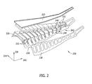
- FIG. 2 is an exploded view of an exemplary heat shield assembly 200 that may be coupled to an aft pylon fairing (not shown) and/or wing 130 on aircraft 100.
- heat shield assembly 200 has a longitudinal or X-axis 202, a lateral or Y-axis 204 that is substantially perpendicular to the X-axis 202, and a vertical or Z-axis 206 that is substantially perpendicular to the X-axis 202 and the Y-axis 204.
- heat shield assembly 200 includes a generally concave lower skin 210 that generally extends in the X-Y plane, a generally convex upper skin 220 that generally extends in the X-Y plane, a pair of side skins 230 that generally extend in the X-Z plane, and a plurality of ribs 240 extending between lower skin 210 and upper skin 220 in the Y-Z plane.
- lower skin 210 is disposed generally above an engine exhaust (not shown) and is fabricated from a material that substantially withstands relatively high temperatures without substantially creeping.
- lower skin 210 is fabricated from a titanium material.
- lower skin 210 may be fabricated from any material that enables lower skin 210 to function as described herein.
- upper skin 220 is a fluid barrier that at least partially defines a channel (not shown) that is configured to channel a fluid therethrough to facilitate cooling heat shield assembly 200. Because of their relative positions, during operation in the exemplary embodiment, lower skin 210 is generally at a higher temperature than upper skin 220, and/or upper skin 220 is generally at a lower temperature than lower skin 210. Alternatively, lower skin 210 and/or upper skin 220 may be disposed in any position and/or orientation that enables heat shield assembly 200 to function as described herein.
- side skins 230 extend between lower skin 210 and upper skin 220 and are spaced along the Y-axis 204 to at least partially define a heat shield cavity 242 therein.
- the ribs 240 are disposed within cavity 242 and generally extend between lower skin 210 and upper skin 220 and between side skins 230.
- the ribs 240 are spaced along the X-axis 202 to at least partially define a plurality of heat shield bays 244 within cavity 242.
- thermal insulation support 250 is positioned within each bay 244. More specifically, thermal insulation support 250 is disposed between lower skin 210 and upper skin 220 and longitudinally aligned substantially perpendicularly to side skins 230. As shown in FIG. 3 , thermal insulation support 250 includes a body 260 that includes a first edge portion 270 and a second edge portion 280 extending generally along a longitudinal axis of body 260. More specifically, in the exemplary embodiment, first edge portion 270 and second edge portion 280 are aligned generally in a parallel orientation along the Y-axis 204. Alternatively, first edge portion 270 and/or second edge portion 280 may be aligned and/or oriented in any configuration that enables thermal insulation support 250 to function as described herein.
- body 260 has a wave-shaped configuration extending between first edge portion 270 and second edge portion 280. More specifically, the wave-shaped configuration includes at least one wave 290 extending between first edge portion 270 and second edge portion 280.
- the wave 290 enables body 260 to provide support to an insulation block, described in more detail below, within a high sonic environment while being relatively light weight and/or thin.
- wave 290 has a body or wave height 292 that is less than approximately 1.0 inch (in.) and a wave length 294 that is less than approximately 4.0 in. More particularly, in the exemplary embodiment, wave height 292 is less than approximately 0.5 in., and wave length 294 is between approximately 1.0 in. and approximately 3.0 in. Even more particularly, wave height 292 is approximately 0.25 in., and wave length 294 is approximately 2.0 in. In one embodiment, the wave-shaped configuration includes a plurality of waves 290 that are spaced along the longitudinal axis in a staggered configuration.
- each wave 290 includes a peak and/or nadir at a distance from first edge portion 270 and/or second edge portion 280 that is different from at least one other wave 290.
- body 260 has an egg carton-like configuration.
- body 260 may have any configuration that enables thermal insulation support 250 to function as described herein.
- first flange 300 and/or a second flange 310 enable body 260 to be suspended within bay 244. That is, first flange 300 and/or second flange 310 enable thermal insulation support 250 to be coupled within heat shield assembly 200.
- first flange 300 and second flange 310 extend generally upwardly from body 260. More specifically a first flange 300 extends substantially perpendicularly from first edge portion 270, and/or second flange 310 extends substantially perpendicularly from second edge portion 280.
- the first edge portion 270 and/or second edge portion 280 includes a curved heel such that first flange 300 and/or second flange 310 extend generally seamlessly from body 260.
- first flange 300 and/or second flange 310 are integrally formed such that thermal insulation support 250 is substantially seamless.
- first flange 300 and/or second flange 310 may be aligned and/or oriented in any configuration that enables thermal insulation support 250 to function as described herein.
- first flange 300 and/or second flange 310 are moveable between a base configuration and a deflected configuration. More specifically, in the exemplary embodiment, first flange 300 and/or second flange 310 is rotatable generally about the curved heel such that first flange 300 and/or second flange 310 are moved from extending substantially perpendicularly from body 260. In the exemplary embodiment, first flange 300 and/or second flange 310 are biased toward the base configuration. Alternatively, first flange 300 and/or second flange 310 may move in any direction and/or be biased in any position that enables thermal insulation support 250 to function as described herein.
- first flange 300 and/or second flange 310 have a flange height 312 that enables thermal insulation 250 to be coupled to ribs 240. More specifically, first flange 300 is coupled to a first rib 240a and second flange 310 is coupled to a second rib 240b. For example, first flange 300 and second flange 310 are coupled to ribs 240 using a plurality of rivets. Alternatively, first flange 300 and/or second flange 310 are coupled to ribs 240 using any coupling mechanism that enables thermal insulation support 250 to function as described herein.
- flange height 312 is greater than wave height 292.
- flange height 312 is at least approximately 0.25 in. More particularly, in the exemplary embodiment, flange height 312 is between approximately 0.5 in. and approximately 1.0 in. Even more particularly, flange height 312 is approximately 0.75 in.
- first flange 300 and/or second flange 310 may have any height that enables thermal insulation support 250 to function as described herein.
- bays 244 decrease in size along the X-axis 202 in at least some embodiments, and each thermal insulation support 250 is sized and/or configured to fit within a respective bay 244. Accordingly, flange height 312 of first flange 300 may be different from flange height 312 of second flange 310.
- thermal insulation support 250 is fabricated from a heat-resistant material configured to withstand relatively high heat without substantially creeping.
- thermal insulation support 250 is fabricated from a titanium and/or a nickel-based material.
- thermal insulation support 250 may be fabricated from any material that enables thermal insulation support 250 to function as described herein.
- an insulation block 320 (shown in FIG. 2 ) is disposed on top of thermal insulation support 250 between first flange 300 and second flange 310. More specifically, in the exemplary embodiment, insulation block 320 is disposed remote from a warmer lower skin 210 and/or adjacent to a cooler upper skin 220.
- the insulation block 320 is a fabricated from a compliant material. Alternatively, insulation block 320 may be fabricated from any material that enables insulation block 320 to function as described herein.
- first flange 300 and/or second flange 310 are flexed towards the deflected configuration to facilitate decreasing a width of thermal insulation support 250.
- thermal insulation support 250 is positioned within bay 244 such that first flange 300 and/or second flange 310 are oriented to extend upwardly (i.e., away from lower skin 210 and/or towards upper skin 220).
- the first flange 300 is coupled to first rib 240a
- second flange 310 is coupled to second rib 240b.
- the insulation block 320 is positioned on top of thermal insulation support 250.
- the examples described herein relate generally to insulation systems and, more particularly, to a thermal insulation support for use in supporting a thermal insulation block within a heat shield.
- the embodiments described herein enable a buffer to be provided between a thermal insulation block and a lower skin of a heat shield assembly.
- the buffer facilitates increasing an efficiency of the heat shield assembly without substantially increasing a weight of the insulation and/or a cost or time associated with the installation of the insulation.
Landscapes
- Engineering & Computer Science (AREA)
- Aviation & Aerospace Engineering (AREA)
- Mechanical Engineering (AREA)
- Exhaust Silencers (AREA)
- Thermal Insulation (AREA)
- Filling Or Discharging Of Gas Storage Vessels (AREA)
Abstract
Description
- The present disclosure relates generally to insulation systems and, more particularly, to a support for use in supporting a thermal insulation block within a heat shield.
- At least some known heat shield assemblies are positioned above an engine exhaust to facilitate reducing heat transfer. For example, due to its proximity to the engine exhaust, the lower skin of at least some known heat shield assemblies may be exposed to relatively high temperatures. To facilitate increasing an efficiency of the heat shield assembly, at least some known engines include insulation positioned within the heat shield assembly directly against the lower skin. To accommodate increased exhaust temperatures, at least some known heat shield assemblies use a thicker insulation. Increasing a thickness of the insulation, however, may increase a weight associated with the insulation and/or heat shield assembly.
- According to an aspect of the present disclosure there is provided a method is provided for use in installing an insulation support within a heat shield assembly. The method includes coupling a first flange to a first wall of the heat shield assembly. The first flange extends a first distance from a first edge portion of a body. The first edge portion extends generally along a longitudinal axis of the body. A second flange is coupled to a second wall of the heat shield assembly. The second flange extends a second distance from a second edge portion of the body. The second edge portion extends generally along the longitudinal axis of the body.
- Advantageously further comprising forming the body to have a wave-shaped configuration extending between the first edge portion and the second edge portion.
- Advantageously further comprising forming at least one of the first edge portion and the second edge portion to include a curved heel.
- Advantageously further comprising forming at least one of the first flange and the second flange to extend substantially perpendicularly from the body and extend away from the lower skin.
- Advantageously further comprising integrally forming the body, the first flange, and the second flange such that the thermal insulation support is substantially seamless.
- Advantageously further comprising forming the thermal insulation support at least partially from a resilient material that enables at least one of the first flange and the second flange to deflect from a base position.
- Advantageously further comprising positioning an insulation block on top of the thermal insulation support.
- According to a further aspect of the present disclosure there is provided a thermal insulation support is provided for use within a heat shield assembly. The thermal insulation support includes a body including a first edge portion and a second edge portion extending generally along a longitudinal axis of the body. A first flange extends a first distance from the first edge portion of the body. The first flange is coupleable to a first wall of the heat shield assembly. A second flange extends a second distance from the second edge portion of the body. The second flange is coupleable to a second wall of the heat shield assembly.
- Advantageously the body has a wave-shaped configuration extending between said first edge portion and said second edge portion, the wave-shaped configuration including a plurality of waves extending between said first edge portion and said second edge portion, said plurality of waves spaced along the longitudinal axis in a staggered configuration.
- Advantageously at least one of said first edge portion and said second edge portion comprises a curved heel.
- Advantageously at least one of said first flange and said second flange extend substantially perpendicularly from said body and extend away from the lower skin.
- Advantageously the body, said first flange, and said second flange are integrally formed such that said thermal insulation support is substantially seamless.
- Advantageously the thermal insulation support is fabricated at least partially from a resilient material that enables at least one of said first flange and said second flange to deflect from a base position.
- According to yet a further aspect of the present disclosure there is provided a heat shield assembly is provided. The heat shield assembly includes a lower skin, an upper skin, and a plurality of ribs extending between the lower skin and the upper skin. At least one thermal insulation support is disposed between the lower skin and the upper skin. The thermal insulation support includes a body that includes a first edge portion and a second edge portion extending generally along a longitudinal axis of the body. A first flange extends a first distance from the first edge portion of the body. A second flange extends a second distance from the second edge portion of the body. The first flange is coupled to a first rib of the plurality of ribs, and the second flange is coupled to a second rib of the plurality of ribs.
- Advantageously the body has a wave-shaped configuration extending between said first edge portion and said second edge portion, the wave-shaped configuration including a plurality of waves extending between said first edge portion and said second edge portion, said plurality of waves spaced along the longitudinal axis in a staggered configuration.
- Advantageously at least one of said first edge portion and said second edge portion comprises a curved heel.
- Advantageously at least one of said first flange and said second flange extend substantially perpendicularly from said body and extend away from the lower skin.
- Advantageously the body, said first flange, and said second flange are integrally formed such that said thermal insulation support is substantially seamless.
- Advantageously further comprising an insulation block disposed between said thermal insulation support and said upper skin.
- Advantageously the heat shield is coupled to an aircraft engine.
- The features, functions, and advantages described herein may be achieved independently in various embodiments of the present disclosure or may be combined in yet other embodiments, further details of which may be seen with reference to the following description and drawings.
-
-
FIG. 1 is a plan view of an exemplary aircraft; -
FIG. 2 is an exploded view of an exemplary heat shield assembly that may be used with the aircraft shown inFIG. 1 ; and -
FIG. 3 is a perspective view of an exemplary thermal insulation support that may be used with the heat shield assembly shown inFIG. 2 . - Although specific features of various embodiments may be shown in some drawings and not in others, this is for convenience only. Any feature of any drawing may be referenced and/or claimed in combination with any feature of any other drawing.
- The present disclosure relates generally to insulation systems and, more particularly, to a thermal insulation support that maybe used to support a thermal insulation block within a heat shield assembly. In one embodiment, a thermal insulation support includes a body including a first edge portion and a second edge portion extending generally along a longitudinal axis of the body. The body has a wave-shaped configuration extending between the first edge portion and the second edge portion. A first flange extending generally upwardly from the first edge portion of the body is coupled to a first wall, and a second flange extending generally upwardly from the second edge portion of the body is coupled to a second wall. An insulation block is positioned within the heat shield assembly on top of the thermal insulation support. Accordingly, the thermal insulation support enables the insulation block to be positioned within the heat shield assembly remote from a warmer lower skin of the heat shield assembly and/or adjacent to a cooler upper skin of the heat shield assembly.
- As used herein, an element or step recited in the singular and proceeded with the word "a" or "an" should be understood as not excluding plural elements or steps unless such exclusion is explicitly recited. Moreover, references to "one embodiment" of the present invention and/or the "exemplary embodiment" are not intended to be interpreted as excluding the existence of additional embodiments that also incorporate the recited features.
-
FIG. 1 is a plan view of anexemplary aircraft 100 including abody 110. In the exemplary embodiment,body 110 includes afuselage 120 and a pair ofwings 130 extending fromfuselage 120. In the exemplary embodiment, at least oneengine 140 is coupled to eachwing 130 to provide thrust toaircraft 100.Aircraft 100 may include any number ofengines 140 that enablesaircraft 100 to function as described herein. -
FIG. 2 is an exploded view of an exemplaryheat shield assembly 200 that may be coupled to an aft pylon fairing (not shown) and/orwing 130 onaircraft 100. In the exemplary embodiment,heat shield assembly 200 has a longitudinal or X-axis 202, a lateral or Y-axis 204 that is substantially perpendicular to theX-axis 202, and a vertical or Z-axis 206 that is substantially perpendicular to theX-axis 202 and the Y-axis 204. In the exemplary embodiment,heat shield assembly 200 includes a generally concavelower skin 210 that generally extends in the X-Y plane, a generally convexupper skin 220 that generally extends in the X-Y plane, a pair ofside skins 230 that generally extend in the X-Z plane, and a plurality ofribs 240 extending betweenlower skin 210 andupper skin 220 in the Y-Z plane. - In one example,
lower skin 210 is disposed generally above an engine exhaust (not shown) and is fabricated from a material that substantially withstands relatively high temperatures without substantially creeping. For example, in the exemplary embodiment,lower skin 210 is fabricated from a titanium material. Alternatively,lower skin 210 may be fabricated from any material that enableslower skin 210 to function as described herein. - In one example,
upper skin 220 is a fluid barrier that at least partially defines a channel (not shown) that is configured to channel a fluid therethrough to facilitate coolingheat shield assembly 200. Because of their relative positions, during operation in the exemplary embodiment,lower skin 210 is generally at a higher temperature thanupper skin 220, and/orupper skin 220 is generally at a lower temperature thanlower skin 210. Alternatively,lower skin 210 and/orupper skin 220 may be disposed in any position and/or orientation that enablesheat shield assembly 200 to function as described herein. - In one example, side skins 230 extend between
lower skin 210 andupper skin 220 and are spaced along the Y-axis 204 to at least partially define aheat shield cavity 242 therein. Theribs 240 are disposed withincavity 242 and generally extend betweenlower skin 210 andupper skin 220 and between side skins 230. Theribs 240 are spaced along theX-axis 202 to at least partially define a plurality ofheat shield bays 244 withincavity 242. - In an example, at least one
thermal insulation support 250 is positioned within eachbay 244. More specifically,thermal insulation support 250 is disposed betweenlower skin 210 andupper skin 220 and longitudinally aligned substantially perpendicularly to side skins 230. As shown inFIG. 3 ,thermal insulation support 250 includes abody 260 that includes afirst edge portion 270 and asecond edge portion 280 extending generally along a longitudinal axis ofbody 260. More specifically, in the exemplary embodiment,first edge portion 270 andsecond edge portion 280 are aligned generally in a parallel orientation along the Y-axis 204. Alternatively,first edge portion 270 and/orsecond edge portion 280 may be aligned and/or oriented in any configuration that enablesthermal insulation support 250 to function as described herein. - In one example,
body 260 has a wave-shaped configuration extending betweenfirst edge portion 270 andsecond edge portion 280. More specifically, the wave-shaped configuration includes at least onewave 290 extending betweenfirst edge portion 270 andsecond edge portion 280. Thewave 290 enablesbody 260 to provide support to an insulation block, described in more detail below, within a high sonic environment while being relatively light weight and/or thin. - In one example, wave 290 has a body or
wave height 292 that is less than approximately 1.0 inch (in.) and awave length 294 that is less than approximately 4.0 in. More particularly, in the exemplary embodiment,wave height 292 is less than approximately 0.5 in., andwave length 294 is between approximately 1.0 in. and approximately 3.0 in. Even more particularly,wave height 292 is approximately 0.25 in., andwave length 294 is approximately 2.0 in. In one embodiment, the wave-shaped configuration includes a plurality ofwaves 290 that are spaced along the longitudinal axis in a staggered configuration. That is, in such an embodiment, eachwave 290 includes a peak and/or nadir at a distance fromfirst edge portion 270 and/orsecond edge portion 280 that is different from at least oneother wave 290. For example, in one embodiment,body 260 has an egg carton-like configuration. Alternatively,body 260 may have any configuration that enablesthermal insulation support 250 to function as described herein. - In one example, a
first flange 300 and/or asecond flange 310 enablebody 260 to be suspended withinbay 244. That is,first flange 300 and/orsecond flange 310 enablethermal insulation support 250 to be coupled withinheat shield assembly 200. In the exemplary embodiment,first flange 300 andsecond flange 310 extend generally upwardly frombody 260. More specifically afirst flange 300 extends substantially perpendicularly fromfirst edge portion 270, and/orsecond flange 310 extends substantially perpendicularly fromsecond edge portion 280. Thefirst edge portion 270 and/orsecond edge portion 280 includes a curved heel such thatfirst flange 300 and/orsecond flange 310 extend generally seamlessly frombody 260. For example, in the exemplary embodiment,body 260,first flange 300, andsecond flange 310 are integrally formed such thatthermal insulation support 250 is substantially seamless. Alternatively,first flange 300 and/orsecond flange 310 may be aligned and/or oriented in any configuration that enablesthermal insulation support 250 to function as described herein. - In one example,
first flange 300 and/orsecond flange 310 are moveable between a base configuration and a deflected configuration. More specifically, in the exemplary embodiment,first flange 300 and/orsecond flange 310 is rotatable generally about the curved heel such thatfirst flange 300 and/orsecond flange 310 are moved from extending substantially perpendicularly frombody 260. In the exemplary embodiment,first flange 300 and/orsecond flange 310 are biased toward the base configuration. Alternatively,first flange 300 and/orsecond flange 310 may move in any direction and/or be biased in any position that enablesthermal insulation support 250 to function as described herein. - In one example,
first flange 300 and/orsecond flange 310 have aflange height 312 that enablesthermal insulation 250 to be coupled toribs 240. More specifically,first flange 300 is coupled to a first rib 240a andsecond flange 310 is coupled to a second rib 240b. For example,first flange 300 andsecond flange 310 are coupled toribs 240 using a plurality of rivets. Alternatively,first flange 300 and/orsecond flange 310 are coupled toribs 240 using any coupling mechanism that enablesthermal insulation support 250 to function as described herein. - In one example,
flange height 312 is greater thanwave height 292. For example, in the exemplary embodiment,flange height 312 is at least approximately 0.25 in. More particularly, in the exemplary embodiment,flange height 312 is between approximately 0.5 in. and approximately 1.0 in. Even more particularly,flange height 312 is approximately 0.75 in. Alternatively,first flange 300 and/orsecond flange 310 may have any height that enablesthermal insulation support 250 to function as described herein. For example,bays 244 decrease in size along theX-axis 202 in at least some embodiments, and eachthermal insulation support 250 is sized and/or configured to fit within arespective bay 244. Accordingly,flange height 312 offirst flange 300 may be different fromflange height 312 ofsecond flange 310. - In one example,
thermal insulation support 250 is fabricated from a heat-resistant material configured to withstand relatively high heat without substantially creeping. For example, in the exemplary embodiment,thermal insulation support 250 is fabricated from a titanium and/or a nickel-based material. Alternatively,thermal insulation support 250 may be fabricated from any material that enablesthermal insulation support 250 to function as described herein. - In one example, an insulation block 320 (shown in
FIG. 2 ) is disposed on top ofthermal insulation support 250 betweenfirst flange 300 andsecond flange 310. More specifically, in the exemplary embodiment,insulation block 320 is disposed remote from a warmerlower skin 210 and/or adjacent to a coolerupper skin 220. Theinsulation block 320 is a fabricated from a compliant material. Alternatively,insulation block 320 may be fabricated from any material that enablesinsulation block 320 to function as described herein. - To install
thermal insulation support 250 withinheat shield assembly 200,first flange 300 and/orsecond flange 310 are flexed towards the deflected configuration to facilitate decreasing a width ofthermal insulation support 250. In one example,thermal insulation support 250 is positioned withinbay 244 such thatfirst flange 300 and/orsecond flange 310 are oriented to extend upwardly (i.e., away fromlower skin 210 and/or towards upper skin 220). Thefirst flange 300 is coupled to first rib 240a, andsecond flange 310 is coupled to second rib 240b. Theinsulation block 320 is positioned on top ofthermal insulation support 250. - The examples described herein relate generally to insulation systems and, more particularly, to a thermal insulation support for use in supporting a thermal insulation block within a heat shield. The embodiments described herein enable a buffer to be provided between a thermal insulation block and a lower skin of a heat shield assembly. The buffer facilitates increasing an efficiency of the heat shield assembly without substantially increasing a weight of the insulation and/or a cost or time associated with the installation of the insulation.
- Exemplary embodiments of methods and systems for supporting thermal insulation are described above in detail. The methods and systems are not limited to the specific embodiments described herein, but rather, components of systems and/or steps of the method may be utilized independently and separately from other components and/or steps described herein. Each method step and each component may also be used in combination with other method steps and/or components. Although specific features of various embodiments may be shown in some drawings and not in others, this is for convenience only. Any feature of a drawing may be referenced and/or claimed in combination with any feature of any other drawing.
Claims (15)
- A method of installing an insulation support within a heat shield assembly, said method comprising:coupling a first flange (300) to a first wall of the heat shield assembly, wherein the first flange (300) extends a first distance from a first edge portion (270) of a body (260), the first edge portion (270) extending generally along a longitudinal axis (202) of the body; andcoupling a second flange to a second wall of the heat shield assembly, wherein the second flange extends a second distance from a second edge portion of the body, the second edge portion extending generally along the longitudinal axis (202) of the body
- A method in accordance with claim 1 further comprising forming the body to have a wave-shaped configuration extending between the first edge portion (270) and the second edge portion (280).
- A method in accordance with claim 1 further comprising forming at least one of the first edge portion (270) and the second edge (280) portion to include a curved heel.
- A method in accordance with claim 1 further comprising forming at least one of the first flange (300) and the second flange (310) to extend substantially perpendicularly from the body (260) and extend away from the lower skin (210).
- A method in accordance with claim 1 further comprising positioning an insulation block (320) on top of the thermal insulation support (250).
- A thermal insulation support (250) for use within a heat shield assembly (200), said thermal insulation support comprising:a body (260) comprising a first edge portion (270) and a second edge portion (280) extending generally along a longitudinal axis (202) of said body (260);a first flange (300) extending a first distance from said first edge portion (270) of said body (260), said first flange coupleable to a first wall of the heat shield assembly (200); anda second flange (310) extending a second distance from said second edge portion (280) of said body (260), said second flange (310) coupleable to a second wall of the heat shield assembly (200).
- A thermal insulation support (250) in accordance with claim 6, wherein said body (260) has a wave-shaped configuration extending between said first edge portion (270) and said second edge portion (280), the wave-shaped configuration including a plurality of waves (290) extending between said first edge portion (270) and said second edge portion (280), said plurality of waves (290) spaced along the longitudinal axis (202) in a staggered configuration.
- A thermal insulation support in accordance with claim 6, wherein at least one of said first edge portion (270) and said second edge portion (280) comprises a curved heel.
- A thermal insulation support in accordance with claim 6, wherein at least one of said first flange (300) and said second flange (310) extend substantially perpendicularly from said body (260) and extend away from the lower skin (210).
- A heat shield assembly comprising:a lower skin (210);an upper skin (220);a plurality of ribs (240) extending between said lower skin (210) and said upper skin (220); andat least one thermal insulation support (250) disposed between said lower skin (210) and said upper skin (220), said thermal insulation support (250) comprising a body (260) that comprises a first edge portion (270) and a second edge portion (280) extending generally along a longitudinal axis (202) of said body (260), a first flange (300) extending a first distance from said first edge portion (270) of said body, and a second flange (310) extending a second distance from said second edge portion (280) of said body (260), said first flange coupled to a first rib (240a) of said plurality of ribs (240), said second flange (310) coupled to a second rib (240b) of said plurality of ribs (240).
- A heat shield assembly in accordance with claim 10, wherein said body (260) has a wave-shaped configuration extending between said first edge portion (270) and said second edge portion (280), the wave-shaped configuration including a plurality of waves (290) extending between said first edge portion (270) and said second edge portion (280), said plurality of waves (290) spaced along the longitudinal axis (202) in a staggered configuration.
- A heat shield assembly in accordance with claim 10, wherein at least one of said first edge portion (270) and said second edge portion (280) comprises a curved heel.
- A heat shield assembly in accordance with claim 10, wherein at least one of said first flange (300) and said second flange (310) extend substantially perpendicularly from said body (260) and extend away from the lower skin (210).
- A heat shield assembly in accordance with claim 10 further comprising an insulation block (320) disposed between said thermal insulation support (250) and said upper skin (220).
- A heat shield assembly in accordance with claim 10, wherein the heat shield assembly (200) is coupled to an aircraft engine.
Applications Claiming Priority (1)
| Application Number | Priority Date | Filing Date | Title |
|---|---|---|---|
| US13/441,993 US9783285B2 (en) | 2012-04-09 | 2012-04-09 | Thermal insulation support |
Publications (3)
| Publication Number | Publication Date |
|---|---|
| EP2650211A2 true EP2650211A2 (en) | 2013-10-16 |
| EP2650211A3 EP2650211A3 (en) | 2017-05-10 |
| EP2650211B1 EP2650211B1 (en) | 2020-06-24 |
Family
ID=48047878
Family Applications (1)
| Application Number | Title | Priority Date | Filing Date |
|---|---|---|---|
| EP13162163.3A Not-in-force EP2650211B1 (en) | 2012-04-09 | 2013-04-03 | Thermal insulation support |
Country Status (2)
| Country | Link |
|---|---|
| US (1) | US9783285B2 (en) |
| EP (1) | EP2650211B1 (en) |
Cited By (1)
| Publication number | Priority date | Publication date | Assignee | Title |
|---|---|---|---|---|
| CN105173053A (en) * | 2015-09-21 | 2015-12-23 | 北京临近空间飞行器系统工程研究所 | Connection structure for all carbon-carbon composite material wing |
Families Citing this family (4)
| Publication number | Priority date | Publication date | Assignee | Title |
|---|---|---|---|---|
| US10427778B2 (en) | 2016-03-14 | 2019-10-01 | The Boeing Company | Heat shield assembly and method |
| US11427298B2 (en) | 2019-09-18 | 2022-08-30 | The Boeing Company | Advanced plume suppressing segmented heat shield |
| US11338902B2 (en) | 2019-09-18 | 2022-05-24 | The Boeing Company | Heat shield for an aircraft |
| US12252245B2 (en) | 2021-01-20 | 2025-03-18 | The Boeing Company | Beaded composite structures and methods for manufacturing beaded composite structures |
Family Cites Families (10)
| Publication number | Priority date | Publication date | Assignee | Title |
|---|---|---|---|---|
| FR2166542A5 (en) * | 1971-12-29 | 1973-08-17 | Bronzavia Sa | |
| FR2534349A1 (en) | 1982-10-12 | 1984-04-13 | Jehier Sa | Insulating mattress especially for aircraft fuselages |
| US5906097A (en) | 1997-03-28 | 1999-05-25 | The Boeing Company | Engine flow control device |
| US6177157B1 (en) | 1998-10-30 | 2001-01-23 | Donald Cota | Thermal shield |
| US6983912B2 (en) | 2002-04-30 | 2006-01-10 | The Boeing Company | Hybrid exhaust heat shield for pylon mounted gas turbine engines |
| US7850058B2 (en) * | 2004-03-31 | 2010-12-14 | The Boeing Company | Superplastic forming of titanium assemblies |
| US8186325B2 (en) | 2006-01-05 | 2012-05-29 | Federal-Mogul World Wide, Inc. | Heat shield having locating and retention features |
| FR2913665B1 (en) | 2007-03-16 | 2009-06-05 | Airbus France Sa | LOWER REAR AERODYNAMIC FAIRING FOR AN AIRCRAFT ENGINE CLAMPING DEVICE |
| US7927686B2 (en) | 2007-10-11 | 2011-04-19 | The Boeing Company | Composite heat shield |
| US7943227B2 (en) | 2007-10-11 | 2011-05-17 | The Boeing Company | Ceramic heat shield |
-
2012
- 2012-04-09 US US13/441,993 patent/US9783285B2/en not_active Expired - Fee Related
-
2013
- 2013-04-03 EP EP13162163.3A patent/EP2650211B1/en not_active Not-in-force
Non-Patent Citations (1)
| Title |
|---|
| None |
Cited By (2)
| Publication number | Priority date | Publication date | Assignee | Title |
|---|---|---|---|---|
| CN105173053A (en) * | 2015-09-21 | 2015-12-23 | 北京临近空间飞行器系统工程研究所 | Connection structure for all carbon-carbon composite material wing |
| CN105173053B (en) * | 2015-09-21 | 2017-05-17 | 北京临近空间飞行器系统工程研究所 | Connection structure for all carbon-carbon composite material wing |
Also Published As
| Publication number | Publication date |
|---|---|
| US9783285B2 (en) | 2017-10-10 |
| EP2650211B1 (en) | 2020-06-24 |
| US20130266769A1 (en) | 2013-10-10 |
| EP2650211A3 (en) | 2017-05-10 |
Similar Documents
| Publication | Publication Date | Title |
|---|---|---|
| EP2650211A2 (en) | Thermal insulation support | |
| US8684674B2 (en) | Anti-rotation shroud for turbine engines | |
| US8777164B2 (en) | Air intake structure for an aircraft nacelle | |
| RU2429168C2 (en) | Aircraft power plant with fan housing support assembly mounted on two separate elements | |
| US8955796B2 (en) | Aft aerodynamic fairing with improved thermal resistance for a pylon for attaching an aircraft propelling assembly | |
| US8579231B2 (en) | Method of manufacture by superplastic forming and by fishplating of a rib for an aerodynamic fairing of an aircraft engine mounting pylon | |
| US10464683B2 (en) | Aircraft engine assembly, comprising flexible force transmitting devices radially arranged between the thrust reversal cowls and the engine | |
| US8814080B2 (en) | Aerodynamic aft fairing of an aircraft engine suspension pylon | |
| US8607453B2 (en) | Method of manufacture by superplastic forming and by fishplating of a rib for an aerodynamic fairing of an aircraft engine mounting pylon | |
| CN111315652B (en) | Airplane wings and aircraft | |
| CN103958350B (en) | There is the composite panel of built-in sampling collector | |
| EP3782902B1 (en) | Heat shield flange sliding joint | |
| EP3676173B1 (en) | Noise abatement systems for retractable leading edge wing slats of an aircraft wing assembly | |
| US9688412B2 (en) | Aerodynamic fairing | |
| US9523502B2 (en) | Low profile push-lock device | |
| US9573672B2 (en) | Device for protecting the front spar structure of a central casing of an aircraft wing and at least one piece of equipment located in said wing | |
| EP3750813B1 (en) | Fire seal assemblies for aircraft engines | |
| US9604727B2 (en) | Aerodynamic fairing | |
| CN108657445A (en) | Metal fireproof seal system and aircraft for aircraft engine installation part | |
| EP3150807A1 (en) | Trailing edge core compartment vent for an aircraft engine | |
| US20120318380A1 (en) | Turbojet engine nacelle provided with a cooling assembly for cooling a component | |
| US11807375B2 (en) | Aircraft nacelle comprising a seal system with a spring for a cap of said nacelle | |
| US11781482B2 (en) | Heat shield assembly for use with an aircraft engine | |
| EP4509400A1 (en) | Insulation blanket assemblies and methods | |
| CN117550061A (en) | An antenna array arrangement structure on the tail wing of an aircraft and its design method |
Legal Events
| Date | Code | Title | Description |
|---|---|---|---|
| PUAI | Public reference made under article 153(3) epc to a published international application that has entered the european phase |
Free format text: ORIGINAL CODE: 0009012 |
|
| 17P | Request for examination filed |
Effective date: 20130403 |
|
| AK | Designated contracting states |
Kind code of ref document: A2 Designated state(s): AL AT BE BG CH CY CZ DE DK EE ES FI FR GB GR HR HU IE IS IT LI LT LU LV MC MK MT NL NO PL PT RO RS SE SI SK SM TR |
|
| AX | Request for extension of the european patent |
Extension state: BA ME |
|
| PUAL | Search report despatched |
Free format text: ORIGINAL CODE: 0009013 |
|
| AK | Designated contracting states |
Kind code of ref document: A3 Designated state(s): AL AT BE BG CH CY CZ DE DK EE ES FI FR GB GR HR HU IE IS IT LI LT LU LV MC MK MT NL NO PL PT RO RS SE SI SK SM TR |
|
| AX | Request for extension of the european patent |
Extension state: BA ME |
|
| RIC1 | Information provided on ipc code assigned before grant |
Ipc: B64D 33/04 20060101ALI20170404BHEP Ipc: B64C 3/32 20060101AFI20170404BHEP Ipc: B64D 27/18 20060101ALI20170404BHEP |
|
| STAA | Information on the status of an ep patent application or granted ep patent |
Free format text: STATUS: EXAMINATION IS IN PROGRESS |
|
| 17Q | First examination report despatched |
Effective date: 20181129 |
|
| GRAP | Despatch of communication of intention to grant a patent |
Free format text: ORIGINAL CODE: EPIDOSNIGR1 |
|
| STAA | Information on the status of an ep patent application or granted ep patent |
Free format text: STATUS: GRANT OF PATENT IS INTENDED |
|
| INTG | Intention to grant announced |
Effective date: 20200120 |
|
| GRAS | Grant fee paid |
Free format text: ORIGINAL CODE: EPIDOSNIGR3 |
|
| GRAA | (expected) grant |
Free format text: ORIGINAL CODE: 0009210 |
|
| STAA | Information on the status of an ep patent application or granted ep patent |
Free format text: STATUS: THE PATENT HAS BEEN GRANTED |
|
| AK | Designated contracting states |
Kind code of ref document: B1 Designated state(s): AL AT BE BG CH CY CZ DE DK EE ES FI FR GB GR HR HU IE IS IT LI LT LU LV MC MK MT NL NO PL PT RO RS SE SI SK SM TR |
|
| REG | Reference to a national code |
Ref country code: GB Ref legal event code: FG4D |
|
| REG | Reference to a national code |
Ref country code: CH Ref legal event code: EP |
|
| REG | Reference to a national code |
Ref country code: AT Ref legal event code: REF Ref document number: 1283642 Country of ref document: AT Kind code of ref document: T Effective date: 20200715 |
|
| REG | Reference to a national code |
Ref country code: DE Ref legal event code: R096 Ref document number: 602013070093 Country of ref document: DE |
|
| REG | Reference to a national code |
Ref country code: IE Ref legal event code: FG4D |
|
| PG25 | Lapsed in a contracting state [announced via postgrant information from national office to epo] |
Ref country code: GR Free format text: LAPSE BECAUSE OF FAILURE TO SUBMIT A TRANSLATION OF THE DESCRIPTION OR TO PAY THE FEE WITHIN THE PRESCRIBED TIME-LIMIT Effective date: 20200925 Ref country code: FI Free format text: LAPSE BECAUSE OF FAILURE TO SUBMIT A TRANSLATION OF THE DESCRIPTION OR TO PAY THE FEE WITHIN THE PRESCRIBED TIME-LIMIT Effective date: 20200624 Ref country code: NO Free format text: LAPSE BECAUSE OF FAILURE TO SUBMIT A TRANSLATION OF THE DESCRIPTION OR TO PAY THE FEE WITHIN THE PRESCRIBED TIME-LIMIT Effective date: 20200924 Ref country code: SE Free format text: LAPSE BECAUSE OF FAILURE TO SUBMIT A TRANSLATION OF THE DESCRIPTION OR TO PAY THE FEE WITHIN THE PRESCRIBED TIME-LIMIT Effective date: 20200624 Ref country code: LT Free format text: LAPSE BECAUSE OF FAILURE TO SUBMIT A TRANSLATION OF THE DESCRIPTION OR TO PAY THE FEE WITHIN THE PRESCRIBED TIME-LIMIT Effective date: 20200624 |
|
| REG | Reference to a national code |
Ref country code: LT Ref legal event code: MG4D |
|
| PG25 | Lapsed in a contracting state [announced via postgrant information from national office to epo] |
Ref country code: RS Free format text: LAPSE BECAUSE OF FAILURE TO SUBMIT A TRANSLATION OF THE DESCRIPTION OR TO PAY THE FEE WITHIN THE PRESCRIBED TIME-LIMIT Effective date: 20200624 Ref country code: BG Free format text: LAPSE BECAUSE OF FAILURE TO SUBMIT A TRANSLATION OF THE DESCRIPTION OR TO PAY THE FEE WITHIN THE PRESCRIBED TIME-LIMIT Effective date: 20200924 Ref country code: LV Free format text: LAPSE BECAUSE OF FAILURE TO SUBMIT A TRANSLATION OF THE DESCRIPTION OR TO PAY THE FEE WITHIN THE PRESCRIBED TIME-LIMIT Effective date: 20200624 Ref country code: HR Free format text: LAPSE BECAUSE OF FAILURE TO SUBMIT A TRANSLATION OF THE DESCRIPTION OR TO PAY THE FEE WITHIN THE PRESCRIBED TIME-LIMIT Effective date: 20200624 |
|
| REG | Reference to a national code |
Ref country code: NL Ref legal event code: MP Effective date: 20200624 |
|
| REG | Reference to a national code |
Ref country code: AT Ref legal event code: MK05 Ref document number: 1283642 Country of ref document: AT Kind code of ref document: T Effective date: 20200624 |
|
| PG25 | Lapsed in a contracting state [announced via postgrant information from national office to epo] |
Ref country code: NL Free format text: LAPSE BECAUSE OF FAILURE TO SUBMIT A TRANSLATION OF THE DESCRIPTION OR TO PAY THE FEE WITHIN THE PRESCRIBED TIME-LIMIT Effective date: 20200624 Ref country code: AL Free format text: LAPSE BECAUSE OF FAILURE TO SUBMIT A TRANSLATION OF THE DESCRIPTION OR TO PAY THE FEE WITHIN THE PRESCRIBED TIME-LIMIT Effective date: 20200624 |
|
| PG25 | Lapsed in a contracting state [announced via postgrant information from national office to epo] |
Ref country code: ES Free format text: LAPSE BECAUSE OF FAILURE TO SUBMIT A TRANSLATION OF THE DESCRIPTION OR TO PAY THE FEE WITHIN THE PRESCRIBED TIME-LIMIT Effective date: 20200624 Ref country code: EE Free format text: LAPSE BECAUSE OF FAILURE TO SUBMIT A TRANSLATION OF THE DESCRIPTION OR TO PAY THE FEE WITHIN THE PRESCRIBED TIME-LIMIT Effective date: 20200624 Ref country code: AT Free format text: LAPSE BECAUSE OF FAILURE TO SUBMIT A TRANSLATION OF THE DESCRIPTION OR TO PAY THE FEE WITHIN THE PRESCRIBED TIME-LIMIT Effective date: 20200624 Ref country code: IT Free format text: LAPSE BECAUSE OF FAILURE TO SUBMIT A TRANSLATION OF THE DESCRIPTION OR TO PAY THE FEE WITHIN THE PRESCRIBED TIME-LIMIT Effective date: 20200624 Ref country code: SM Free format text: LAPSE BECAUSE OF FAILURE TO SUBMIT A TRANSLATION OF THE DESCRIPTION OR TO PAY THE FEE WITHIN THE PRESCRIBED TIME-LIMIT Effective date: 20200624 Ref country code: CZ Free format text: LAPSE BECAUSE OF FAILURE TO SUBMIT A TRANSLATION OF THE DESCRIPTION OR TO PAY THE FEE WITHIN THE PRESCRIBED TIME-LIMIT Effective date: 20200624 Ref country code: RO Free format text: LAPSE BECAUSE OF FAILURE TO SUBMIT A TRANSLATION OF THE DESCRIPTION OR TO PAY THE FEE WITHIN THE PRESCRIBED TIME-LIMIT Effective date: 20200624 Ref country code: PT Free format text: LAPSE BECAUSE OF FAILURE TO SUBMIT A TRANSLATION OF THE DESCRIPTION OR TO PAY THE FEE WITHIN THE PRESCRIBED TIME-LIMIT Effective date: 20201026 |
|
| PG25 | Lapsed in a contracting state [announced via postgrant information from national office to epo] |
Ref country code: PL Free format text: LAPSE BECAUSE OF FAILURE TO SUBMIT A TRANSLATION OF THE DESCRIPTION OR TO PAY THE FEE WITHIN THE PRESCRIBED TIME-LIMIT Effective date: 20200624 Ref country code: SK Free format text: LAPSE BECAUSE OF FAILURE TO SUBMIT A TRANSLATION OF THE DESCRIPTION OR TO PAY THE FEE WITHIN THE PRESCRIBED TIME-LIMIT Effective date: 20200624 Ref country code: IS Free format text: LAPSE BECAUSE OF FAILURE TO SUBMIT A TRANSLATION OF THE DESCRIPTION OR TO PAY THE FEE WITHIN THE PRESCRIBED TIME-LIMIT Effective date: 20201024 |
|
| REG | Reference to a national code |
Ref country code: DE Ref legal event code: R097 Ref document number: 602013070093 Country of ref document: DE |
|
| PG25 | Lapsed in a contracting state [announced via postgrant information from national office to epo] |
Ref country code: DK Free format text: LAPSE BECAUSE OF FAILURE TO SUBMIT A TRANSLATION OF THE DESCRIPTION OR TO PAY THE FEE WITHIN THE PRESCRIBED TIME-LIMIT Effective date: 20200624 |
|
| PLBE | No opposition filed within time limit |
Free format text: ORIGINAL CODE: 0009261 |
|
| STAA | Information on the status of an ep patent application or granted ep patent |
Free format text: STATUS: NO OPPOSITION FILED WITHIN TIME LIMIT |
|
| 26N | No opposition filed |
Effective date: 20210325 |
|
| PG25 | Lapsed in a contracting state [announced via postgrant information from national office to epo] |
Ref country code: SI Free format text: LAPSE BECAUSE OF FAILURE TO SUBMIT A TRANSLATION OF THE DESCRIPTION OR TO PAY THE FEE WITHIN THE PRESCRIBED TIME-LIMIT Effective date: 20200624 |
|
| PG25 | Lapsed in a contracting state [announced via postgrant information from national office to epo] |
Ref country code: MC Free format text: LAPSE BECAUSE OF FAILURE TO SUBMIT A TRANSLATION OF THE DESCRIPTION OR TO PAY THE FEE WITHIN THE PRESCRIBED TIME-LIMIT Effective date: 20200624 |
|
| PG25 | Lapsed in a contracting state [announced via postgrant information from national office to epo] |
Ref country code: LU Free format text: LAPSE BECAUSE OF NON-PAYMENT OF DUE FEES Effective date: 20210403 |
|
| REG | Reference to a national code |
Ref country code: BE Ref legal event code: MM Effective date: 20210430 |
|
| PG25 | Lapsed in a contracting state [announced via postgrant information from national office to epo] |
Ref country code: LI Free format text: LAPSE BECAUSE OF NON-PAYMENT OF DUE FEES Effective date: 20210430 Ref country code: CH Free format text: LAPSE BECAUSE OF NON-PAYMENT OF DUE FEES Effective date: 20210430 |
|
| PG25 | Lapsed in a contracting state [announced via postgrant information from national office to epo] |
Ref country code: IE Free format text: LAPSE BECAUSE OF NON-PAYMENT OF DUE FEES Effective date: 20210403 |
|
| PG25 | Lapsed in a contracting state [announced via postgrant information from national office to epo] |
Ref country code: IS Free format text: LAPSE BECAUSE OF FAILURE TO SUBMIT A TRANSLATION OF THE DESCRIPTION OR TO PAY THE FEE WITHIN THE PRESCRIBED TIME-LIMIT Effective date: 20201024 |
|
| PG25 | Lapsed in a contracting state [announced via postgrant information from national office to epo] |
Ref country code: BE Free format text: LAPSE BECAUSE OF NON-PAYMENT OF DUE FEES Effective date: 20210430 |
|
| PG25 | Lapsed in a contracting state [announced via postgrant information from national office to epo] |
Ref country code: HU Free format text: LAPSE BECAUSE OF FAILURE TO SUBMIT A TRANSLATION OF THE DESCRIPTION OR TO PAY THE FEE WITHIN THE PRESCRIBED TIME-LIMIT; INVALID AB INITIO Effective date: 20130403 |
|
| P01 | Opt-out of the competence of the unified patent court (upc) registered |
Effective date: 20230516 |
|
| PG25 | Lapsed in a contracting state [announced via postgrant information from national office to epo] |
Ref country code: CY Free format text: LAPSE BECAUSE OF FAILURE TO SUBMIT A TRANSLATION OF THE DESCRIPTION OR TO PAY THE FEE WITHIN THE PRESCRIBED TIME-LIMIT Effective date: 20200624 |
|
| PG25 | Lapsed in a contracting state [announced via postgrant information from national office to epo] |
Ref country code: MK Free format text: LAPSE BECAUSE OF FAILURE TO SUBMIT A TRANSLATION OF THE DESCRIPTION OR TO PAY THE FEE WITHIN THE PRESCRIBED TIME-LIMIT Effective date: 20200624 |
|
| PG25 | Lapsed in a contracting state [announced via postgrant information from national office to epo] |
Ref country code: TR Free format text: LAPSE BECAUSE OF FAILURE TO SUBMIT A TRANSLATION OF THE DESCRIPTION OR TO PAY THE FEE WITHIN THE PRESCRIBED TIME-LIMIT Effective date: 20200624 |
|
| PGFP | Annual fee paid to national office [announced via postgrant information from national office to epo] |
Ref country code: GB Payment date: 20240429 Year of fee payment: 12 |
|
| PGFP | Annual fee paid to national office [announced via postgrant information from national office to epo] |
Ref country code: DE Payment date: 20240429 Year of fee payment: 12 |
|
| PGFP | Annual fee paid to national office [announced via postgrant information from national office to epo] |
Ref country code: FR Payment date: 20240425 Year of fee payment: 12 |
|
| PG25 | Lapsed in a contracting state [announced via postgrant information from national office to epo] |
Ref country code: MT Free format text: LAPSE BECAUSE OF FAILURE TO SUBMIT A TRANSLATION OF THE DESCRIPTION OR TO PAY THE FEE WITHIN THE PRESCRIBED TIME-LIMIT Effective date: 20200624 |
|
| REG | Reference to a national code |
Ref country code: DE Ref legal event code: R119 Ref document number: 602013070093 Country of ref document: DE |
|
| GBPC | Gb: european patent ceased through non-payment of renewal fee |
Effective date: 20250403 |
|
| PG25 | Lapsed in a contracting state [announced via postgrant information from national office to epo] |
Ref country code: DE Free format text: LAPSE BECAUSE OF NON-PAYMENT OF DUE FEES Effective date: 20251104 |
|
| PG25 | Lapsed in a contracting state [announced via postgrant information from national office to epo] |
Ref country code: GB Free format text: LAPSE BECAUSE OF NON-PAYMENT OF DUE FEES Effective date: 20250403 |
|
| PG25 | Lapsed in a contracting state [announced via postgrant information from national office to epo] |
Ref country code: FR Free format text: LAPSE BECAUSE OF NON-PAYMENT OF DUE FEES Effective date: 20250430 |