EP2649938A1 - Puncturing instrument - Google Patents
Puncturing instrument Download PDFInfo
- Publication number
- EP2649938A1 EP2649938A1 EP11846752.1A EP11846752A EP2649938A1 EP 2649938 A1 EP2649938 A1 EP 2649938A1 EP 11846752 A EP11846752 A EP 11846752A EP 2649938 A1 EP2649938 A1 EP 2649938A1
- Authority
- EP
- European Patent Office
- Prior art keywords
- puncture
- main body
- body case
- needle holder
- needle
- Prior art date
- Legal status (The legal status is an assumption and is not a legal conclusion. Google has not performed a legal analysis and makes no representation as to the accuracy of the status listed.)
- Withdrawn
Links
Images









Classifications
-
- A—HUMAN NECESSITIES
- A61—MEDICAL OR VETERINARY SCIENCE; HYGIENE
- A61B—DIAGNOSIS; SURGERY; IDENTIFICATION
- A61B17/00—Surgical instruments, devices or methods
- A61B17/34—Trocars; Puncturing needles
-
- A—HUMAN NECESSITIES
- A61—MEDICAL OR VETERINARY SCIENCE; HYGIENE
- A61B—DIAGNOSIS; SURGERY; IDENTIFICATION
- A61B5/00—Measuring for diagnostic purposes; Identification of persons
- A61B5/14—Devices for taking samples of blood ; Measuring characteristics of blood in vivo, e.g. gas concentration within the blood, pH-value of blood
- A61B5/1405—Devices for taking blood samples
- A61B5/1411—Devices for taking blood samples by percutaneous method, e.g. by lancet
-
- A—HUMAN NECESSITIES
- A61—MEDICAL OR VETERINARY SCIENCE; HYGIENE
- A61B—DIAGNOSIS; SURGERY; IDENTIFICATION
- A61B5/00—Measuring for diagnostic purposes; Identification of persons
- A61B5/15—Devices for taking samples of blood
- A61B5/150007—Details
- A61B5/150015—Source of blood
- A61B5/150022—Source of blood for capillary blood or interstitial fluid
-
- A—HUMAN NECESSITIES
- A61—MEDICAL OR VETERINARY SCIENCE; HYGIENE
- A61B—DIAGNOSIS; SURGERY; IDENTIFICATION
- A61B5/00—Measuring for diagnostic purposes; Identification of persons
- A61B5/15—Devices for taking samples of blood
- A61B5/150007—Details
- A61B5/150374—Details of piercing elements or protective means for preventing accidental injuries by such piercing elements
- A61B5/150381—Design of piercing elements
- A61B5/150412—Pointed piercing elements, e.g. needles, lancets for piercing the skin
-
- A—HUMAN NECESSITIES
- A61—MEDICAL OR VETERINARY SCIENCE; HYGIENE
- A61B—DIAGNOSIS; SURGERY; IDENTIFICATION
- A61B5/00—Measuring for diagnostic purposes; Identification of persons
- A61B5/15—Devices for taking samples of blood
- A61B5/150007—Details
- A61B5/150374—Details of piercing elements or protective means for preventing accidental injuries by such piercing elements
- A61B5/150381—Design of piercing elements
- A61B5/150503—Single-ended needles
- A61B5/150519—Details of construction of hub, i.e. element used to attach the single-ended needle to a piercing device or sampling device
-
- A—HUMAN NECESSITIES
- A61—MEDICAL OR VETERINARY SCIENCE; HYGIENE
- A61B—DIAGNOSIS; SURGERY; IDENTIFICATION
- A61B5/00—Measuring for diagnostic purposes; Identification of persons
- A61B5/15—Devices for taking samples of blood
- A61B5/150007—Details
- A61B5/150374—Details of piercing elements or protective means for preventing accidental injuries by such piercing elements
- A61B5/150534—Design of protective means for piercing elements for preventing accidental needle sticks, e.g. shields, caps, protectors, axially extensible sleeves, pivotable protective sleeves
- A61B5/150541—Breakable protectors, e.g. caps, shields or sleeves, i.e. protectors separated destructively, e.g. by breaking a connecting area
- A61B5/150549—Protectors removed by rotational movement, e.g. torsion or screwing
-
- A—HUMAN NECESSITIES
- A61—MEDICAL OR VETERINARY SCIENCE; HYGIENE
- A61B—DIAGNOSIS; SURGERY; IDENTIFICATION
- A61B5/00—Measuring for diagnostic purposes; Identification of persons
- A61B5/15—Devices for taking samples of blood
- A61B5/150007—Details
- A61B5/150374—Details of piercing elements or protective means for preventing accidental injuries by such piercing elements
- A61B5/150534—Design of protective means for piercing elements for preventing accidental needle sticks, e.g. shields, caps, protectors, axially extensible sleeves, pivotable protective sleeves
- A61B5/150694—Procedure for removing protection means at the time of piercing
- A61B5/150717—Procedure for removing protection means at the time of piercing manually removed
-
- A—HUMAN NECESSITIES
- A61—MEDICAL OR VETERINARY SCIENCE; HYGIENE
- A61B—DIAGNOSIS; SURGERY; IDENTIFICATION
- A61B5/00—Measuring for diagnostic purposes; Identification of persons
- A61B5/15—Devices for taking samples of blood
- A61B5/151—Devices specially adapted for taking samples of capillary blood, e.g. by lancets, needles or blades
- A61B5/15101—Details
- A61B5/15103—Piercing procedure
- A61B5/15107—Piercing being assisted by a triggering mechanism
-
- A—HUMAN NECESSITIES
- A61—MEDICAL OR VETERINARY SCIENCE; HYGIENE
- A61B—DIAGNOSIS; SURGERY; IDENTIFICATION
- A61B5/00—Measuring for diagnostic purposes; Identification of persons
- A61B5/15—Devices for taking samples of blood
- A61B5/151—Devices specially adapted for taking samples of capillary blood, e.g. by lancets, needles or blades
- A61B5/15101—Details
- A61B5/15115—Driving means for propelling the piercing element to pierce the skin, e.g. comprising mechanisms based on shape memory alloys, magnetism, solenoids, piezoelectric effect, biased elements, resilient elements, vacuum or compressed fluids
- A61B5/15117—Driving means for propelling the piercing element to pierce the skin, e.g. comprising mechanisms based on shape memory alloys, magnetism, solenoids, piezoelectric effect, biased elements, resilient elements, vacuum or compressed fluids comprising biased elements, resilient elements or a spring, e.g. a helical spring, leaf spring, or elastic strap
-
- A—HUMAN NECESSITIES
- A61—MEDICAL OR VETERINARY SCIENCE; HYGIENE
- A61B—DIAGNOSIS; SURGERY; IDENTIFICATION
- A61B5/00—Measuring for diagnostic purposes; Identification of persons
- A61B5/15—Devices for taking samples of blood
- A61B5/151—Devices specially adapted for taking samples of capillary blood, e.g. by lancets, needles or blades
- A61B5/15186—Devices loaded with a single lancet, i.e. a single lancet with or without a casing is loaded into a reusable drive device and then discarded after use; drive devices reloadable for multiple use
- A61B5/15188—Constructional features of reusable driving devices
- A61B5/1519—Constructional features of reusable driving devices comprising driving means, e.g. a spring, for propelling the piercing unit
-
- A—HUMAN NECESSITIES
- A61—MEDICAL OR VETERINARY SCIENCE; HYGIENE
- A61B—DIAGNOSIS; SURGERY; IDENTIFICATION
- A61B5/00—Measuring for diagnostic purposes; Identification of persons
- A61B5/15—Devices for taking samples of blood
- A61B5/151—Devices specially adapted for taking samples of capillary blood, e.g. by lancets, needles or blades
- A61B5/15186—Devices loaded with a single lancet, i.e. a single lancet with or without a casing is loaded into a reusable drive device and then discarded after use; drive devices reloadable for multiple use
- A61B5/15188—Constructional features of reusable driving devices
- A61B5/15192—Constructional features of reusable driving devices comprising driving means, e.g. a spring, for retracting the lancet unit into the driving device housing
- A61B5/15194—Constructional features of reusable driving devices comprising driving means, e.g. a spring, for retracting the lancet unit into the driving device housing fully automatically retracted, i.e. the retraction does not require a deliberate action by the user, e.g. by terminating the contact with the patient's skin
-
- A—HUMAN NECESSITIES
- A61—MEDICAL OR VETERINARY SCIENCE; HYGIENE
- A61B—DIAGNOSIS; SURGERY; IDENTIFICATION
- A61B5/00—Measuring for diagnostic purposes; Identification of persons
- A61B5/15—Devices for taking samples of blood
- A61B5/150007—Details
- A61B5/150175—Adjustment of penetration depth
- A61B5/150183—Depth adjustment mechanism using end caps mounted at the distal end of the sampling device, i.e. the end-caps are adjustably positioned relative to the piercing device housing for example by rotating or screwing
Definitions
- the invention relates to a puncture instrument for puncturing a human body to allow the blood to flow out, for example, in order to measure the blood sugar level.
- a cylindrical main body case having a puncture aperture on the lower end side; a needle holder provided on the puncture aperture side inside the main body case; a first elastic object for moving the needle holder to the puncture aperture side; and a second elastic object for pulling the needle holder, moved to the puncture aperture side by the first elastic object, back to the upper end side inside the main body case (e.g. Patent document 1).
- Patent document 1 Japanese Patent Laid-Open Application No. 2002-085384
- the first elastic object When the puncture is performed with the above-described conventional puncture instrument, the first elastic object rapidly moves the needle holder to the lower end side of the main body case, allowing a puncture needle to puncture a human body.
- the puncture needle is pulled back into the main body case by the first elastic object returning immediately after the puncture, but the first elastic object may repeat the extension and contraction, causing the puncture needle to protrude again toward the human body.
- the second elastic object is thus provided to prevent the puncture needle from protruding again, and its elasticity inhibits the repeated protrusion of the puncture needle.
- the puncture needle may still protrude again in spite of such placement of the second elastic object, and therefore a repeated protrusion prevention mechanism is placed to prevent this repeated protrusion of the puncture needle.
- the repeated protrusion prevention mechanism is provided with, for example, an impact wall to be hit by the needle holder holding the puncture needle that is going to protrude again, and the provision of this impact wall would indeed prevent the repeated protrusion of the puncture needle.
- a purpose of the invention is thus to inhibit the abnormal sound during puncture.
- the invention comprises: a cylindrical main body case having a puncture aperture an the lower end side; a needle holder provided on the puncture aperture side inside the main body case; a first elastic object for moving the needle holder to the puncture aperture side; and a second elastic object for pulling the needle holder, moved to the puncture aperture side by the first elastic object, back to the upper end side inside the main body case, where a rotator which rotates around a rotation shaft fixed to the main body case is provided above a needle holding portion of the needle holder inside the main body case, and where the rotator is coupled with a coupling portion of the needle holder on one of both sides of the rotator with the rotation shaft interposed therebetween and is coupled with the second elastic object on the other side.
- the invention is provided with the second elastic object for pulling the needle holder, moved to the puncture aperture side by the first elastic object, back to the upper end side inside the main body case, where the rotator which rotates around the rotation shaft fixed to the main body case is provided above the needle holding portion of the needle holder inside the main body case, and where the rotator is coupled with the coupling portion of the needle holder on one of both sides of the rotator with the rotation shaft interposed therebetween and is coupled with the second elastic object on the other side.
- the repeated protrusion of the puncture needle is therefore prevented by the rotation of the rotator, which means that no impact sound is created unlike those which are provided with a conventional impact wall. As a result, the generation of an abnormal sound during puncture can be inhibited.
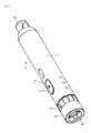
- a puncture instrument in Figure 1 , comprises a cylindrical main body case 1, near an opening on the lower end side of which are attached a puncture depth adjustment ring 2 and a front-end ring 3.
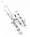
- the adjustment ring 2 and the front-end ring 3 are shown in detail in Figure 2 .
- the puncture depth adjustment ring 2 here, as is well known, is rotated to adjust the puncture depth of a puncture needle 4 (see Figure 13 ).
- the front-end ring 3 is located below the puncture depth adjustment ring 2 on the lower end side, and an opening of this front-end ring 3 constitutes a puncture aperture 5 of the main body case 1.
- an operation button 6 to eject the puncture needle 4, as is well known.
- a puncture button 7 for the puncture needle 4 is placed on the surface in the middle of the main body case 1.
- a base member 8, a needle holder 9 slidably attached to this base member 8, and a puncture needle ejecting member 10 also slidably attached to this base member 8 are provided inside the main body case 1.
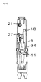
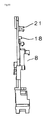
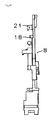
- the base member 8 is configured as shown in Figures 6A through 6F .
- Figure 6A is a top perspective view of the base member 8;
- Figure 6B is a bottom perspective view of the base member 8;
- Figure 6C is a top view of the base member 8;
- Figure 6D is a bottom view of the base member 8;
- Figure 6E is a side view of the base member 8 viewed from one side;
- Figure 6F is a side view of the base member 8 viewed from the other side.
- the base member 8 is fixed inside the main body case 1. As described next in detail, the needle holder 9 and the puncture needle ejecting member 10 are slidably attached in relation to the fixed base member 8.
- Outwardly protruding attachment portions 11 are provided on the top surface in the middle of the base member 8.
- the puncture button 7 is attached to these attachment portions 11 through an opening 12 of the main body case 1.
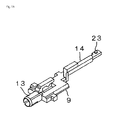
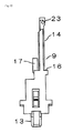
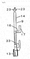
- the needle holder 9 is configured as shown in Figures 7A through 7E .
- Figure 7A is a top perspective view of a needle holder 9;
- Figure 7B is a bottom view of the needle holder 9;
- Figure 7C is a top view of the needle holder 9;
- Figure 7D is a side view of the needle holder 9 viewed from one side;
- Figure 7E is a side view of the needle holder 9 viewed from the other side.
- a needle holding portion 13 is provided on the lower end side of the needle holder 9.
- a rod-shaped coupling portion 14 is provided higher on the needle holder 9.
- a coil-shaped elastic object 15 shown in Figure 2 is placed around the periphery of the rod-shaped coupling portion 14. The coil-shaped elastic object 15 is attached on the lower end side to an abutment surface 16 provided in the middle of the needle holder 9.
- a protrusion 17, near the abutment surface 16, provided over the periphery of the elastic object 15 is to indicate a state where the needle holder 9 is ready for puncture, as shown in Figure 4 .
- the protrusion 17 is colored (e.g. green).
- the protrusion 17 moves from the state shown in Figure 10 toward the upper end side to the state shown in Figure 4 , the protrusion 17 appears in an indication window 17a provided in the periphery of the main body case 1, indicating to a user that the preparation for puncture is complete.
- the elastic object 15 is attached on the upper end side to an abutment surface 18 provided on the upper end side of the base member 8 shown in Figure 6B or the like. This means that the elastic object 15 is attached to the abutment surface 18 of the base member 8 and to the abutment surface 16 of the needle holder 9, and therefore the elastic object 15 is compressed when the needle holder 9 is moved to the upper end side, as shown in Figure 11 , and is then stretched when the needle holder 9 is moved to the lower end side, as shown in Figure 13 .
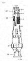
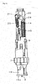
- Figures 10 to 13 illustrate these operating states, which will be described later in detail, where Figure 10 shows a state in which the puncture needle cartridge 19 is not yet attached to the needle holder 9, Figure 11 shows a state in which the puncture needle cartridge 19 is being attached to the needle holder 9, Figure 12 shows a state in which the puncture needle cartridge 19 is already attached to the needle holder 9, and Figure 13 shows a state in which the puncture operation is performed with the puncture needle cartridge 19 being attached to the needle holder 9.
- the coupling portion 14 of the needle holder 9 is coupled on the upper end side to a rotator 20.
- the rotator 20 is shaped into a board which extends in a direction perpendicular to the vertical direction of the main body case 1 in the state where the puncture needle 4 is not yet attached (see Figure 10 ), and is pivotally supported at the center by a rotation shaft 21 provided on the upper end side of the base member 8.
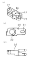
- the rotator 20 is configured as shown in Figures 9A through 9C.
- Figure 9A shows a perspective view of the rotator 20;
- Figure 9B shows a top view of the rotator 20;
- Figure 9C shows a side view of the rotator 20 viewed from one side.
- in the middle of the rotator 20 is formed a through hole 22 through which the rotation shaft 21 enters.
- the through holes 24 are provided at two positions in a manner that they overlap with each other on the front and back sides, as will be understood from Figure 9 .
- the above-described protrusions 23 on the front and back sides shown in Figures 7A to 7E fit into the two through holes 24.
- the elastic objects 15 and 25 are provided below the rotator 20 on the lower end side of the main body case 1.
- the lower end of the elastic object 25 is attached to a protrusion 27 shown in Figures 6B and 6D .
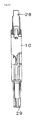
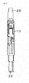
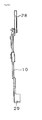
- FIG. 8A is a top perspective view of the puncture needle ejecting member 10
- Figure 8B is a top view of the puncture needle ejecting member 10
- Figure 8C is a bottom view of the puncture needle ejecting member 10
- Figure 8D is a side view of the puncture needle ejecting member 10 viewed from one side
- Figure 8E is a side view of the puncture needle ejecting member 10 viewed from the other side.
- An attachment portion 28 to which the operation button 6 for ejecting the puncture needle cartridge 19 is attached is provided on the upper end side of the puncture needle ejecting member 10, as is well known.
- a pressing portion 29 for ejecting the puncture needle cartridge 19 is provided on the lower end of the puncture needle ejecting member 10.
- a torsion spring 30 for biasing the operation button 6 upward is attached in the middle of the puncture needle ejecting member 10.
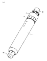
- Figures 3 and 10 show a state in which the puncture needle cartridge 19 is not yet attached to the main body case 1
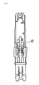
- Figures 4 , 5 , and 11 show a state in which the puncture needle cartridge 19 is being attached to the main body case 1.
- the insertion of the puncture needle cartridge 19 through the puncture aperture 5 at the lower end of the main body case 1 causes a gripping portion 31 of the puncture needle cartridge 19 to be inserted into the needle holding portion 13 on the lower end side of the needle holder 9 shown in Figure 2 , and moves the needle holder 9 upward.
- This upward movement of the needle holder 9, as shown in Figure 11 causes the rotator 20 to be pushed up on the side of the elastic object 15 by the coupling portion 14 of the needle holder 9.
- a protection cap 32 on the front end side of the puncture needle cartridge 19 is twisted off, so that the state shown in Figure 12 is realized.
- a locking protrusion 33 provided on the needle holder 9 engages with a locking hole 34 provided between the attachment portions 11 of the base member 8 shown in Figure 6D and, as a result, the needle holder 9 is held in an upper position as shown in Figure 12 .
- the elastic object 15 is then compressed as shown in Figure 12 along with the upward movement of the needle holder 9.
- the compressed elastic object 15 extends, thereby thrusting the needle holder 9 to the bottom end side and, as a result, the puncture needle 4 sticks out from the skin abutment portion 19a to the skin side to puncture, as shown in Figure 13 .
- the puncture instrument of the embodiment is provided with the elastic object 25 for pulling the needle holder 9, moved to the skin abutment portion 19a (the puncture aperture 5) side by the elastic object 15, back to the upper end side inside the main body case 1, where the rotator 20 which rotates around the rotation shaft 21 is provided above the needle holding portion 13 of the needle holder 9 inside the main body case 1.
- the rotator 20 is coupled with the coupling portion 14 of the needle holder 9 on one side of the rotator 20 and is coupled with the elastic object 25 on the other side of the rotator 20, and the rotation shaft 21 for the rotator 20 is fixed to the main body case 1.
- the rotation shaft 21 for the rotator 20 is fixed to the base member 8, which is fixed to the main body case 1, and therefore the rotation shaft 21 for the rotator 20 is fixed to the main body case 1.
- the embodiment can also prevent the repeated protrusion of the tip of the puncture needle 4.
- the tip of the puncture needle 4 is protruded from the puncture aperture 5 of the main body case 1 as described above. Since the elastic object 25 is then stretched, the next moment the elastic object 25 contracts to its original state, causing the needle holder 9 to be pulled up, and the tip of the puncture needle 4 is returned into the puncture aperture 5 of the main body case 1.
- the tension of the elastic object 25 is larger than the force of the elastic abject 15 to protrude the tip of the puncture needle 4 again outside the puncture aperture 5 of the main body case via the puncture needle cartridge 19, and therefore allows the repeated protrusion of the tip of the puncture needle 4 to be prevented.
- the invention is provided with the second elastic object for pulling the needle holder, moved to the puncture aperture side by the first elastic object, back to the upper end side inside the main body case, where the rotator which rotates around the rotation shaft fixed to the main body case is provided above the needle holding portion of the needle holder inside the main body case, and where the rotator is coupled with the coupling portion of the needle holder on one of both sides of the rotator with the rotation shaft interposed therebetween and is coupled with the second elastic object on the other side.
- the repeated protrusion of the puncture needle is therefore prevented by the rotation of the rotator, which means that no impact sound is created unlike those which are provided with a conventional impact wall. As a result, the generation of an abnormal sound during puncture can be inhibited.
Landscapes
- Health & Medical Sciences (AREA)
- Life Sciences & Earth Sciences (AREA)
- Surgery (AREA)
- Molecular Biology (AREA)
- Animal Behavior & Ethology (AREA)
- Pathology (AREA)
- Engineering & Computer Science (AREA)
- Biomedical Technology (AREA)
- Heart & Thoracic Surgery (AREA)
- Medical Informatics (AREA)
- Veterinary Medicine (AREA)
- Public Health (AREA)
- General Health & Medical Sciences (AREA)
- Biophysics (AREA)
- Hematology (AREA)
- Physics & Mathematics (AREA)
- Dermatology (AREA)
- Nuclear Medicine, Radiotherapy & Molecular Imaging (AREA)
- Measurement Of The Respiration, Hearing Ability, Form, And Blood Characteristics Of Living Organisms (AREA)
- Surgical Instruments (AREA)
Abstract
Description
- This application claims the benefit of Japanese Patent Application No.
2010-271045 filed on December 6, 2010 - The invention relates to a puncture instrument for puncturing a human body to allow the blood to flow out, for example, in order to measure the blood sugar level.
- The configuration of such a puncture instrument would conventionally be as follows.
- That is, it would comprise: a cylindrical main body case having a puncture aperture on the lower end side; a needle holder provided on the puncture aperture side inside the main body case; a first elastic object for moving the needle holder to the puncture aperture side; and a second elastic object for pulling the needle holder, moved to the puncture aperture side by the first elastic object, back to the upper end side inside the main body case (e.g. Patent document 1).
- [Patent document 1] Japanese Patent Laid-Open Application No.
2002-085384 - When the puncture is performed with the above-described conventional puncture instrument, the first elastic object rapidly moves the needle holder to the lower end side of the main body case, allowing a puncture needle to puncture a human body. The puncture needle is pulled back into the main body case by the first elastic object returning immediately after the puncture, but the first elastic object may repeat the extension and contraction, causing the puncture needle to protrude again toward the human body. The second elastic object is thus provided to prevent the puncture needle from protruding again, and its elasticity inhibits the repeated protrusion of the puncture needle.
- However, the puncture needle may still protrude again in spite of such placement of the second elastic object, and therefore a repeated protrusion prevention mechanism is placed to prevent this repeated protrusion of the puncture needle. The repeated protrusion prevention mechanism is provided with, for example, an impact wall to be hit by the needle holder holding the puncture needle that is going to protrude again, and the provision of this impact wall would indeed prevent the repeated protrusion of the puncture needle.
- The impact with such an impact wall, however, creates a large impact sound, which is very obstructive to a puncturing person as an abnormal sound during puncture, and this abnormal sound is required to be inhibited.
- A purpose of the invention is thus to inhibit the abnormal sound during puncture.
- In order to achieve this objective, the invention comprises: a cylindrical main body case having a puncture aperture an the lower end side; a needle holder provided on the puncture aperture side inside the main body case; a first elastic object for moving the needle holder to the puncture aperture side; and a second elastic object for pulling the needle holder, moved to the puncture aperture side by the first elastic object, back to the upper end side inside the main body case, where a rotator which rotates around a rotation shaft fixed to the main body case is provided above a needle holding portion of the needle holder inside the main body case, and where the rotator is coupled with a coupling portion of the needle holder on one of both sides of the rotator with the rotation shaft interposed therebetween and is coupled with the second elastic object on the other side. This allows the intended objective to be achieved.
- The invention is provided with the second elastic object for pulling the needle holder, moved to the puncture aperture side by the first elastic object, back to the upper end side inside the main body case, where the rotator which rotates around the rotation shaft fixed to the main body case is provided above the needle holding portion of the needle holder inside the main body case, and where the rotator is coupled with the coupling portion of the needle holder on one of both sides of the rotator with the rotation shaft interposed therebetween and is coupled with the second elastic object on the other side. The repeated protrusion of the puncture needle is therefore prevented by the rotation of the rotator, which means that no impact sound is created unlike those which are provided with a conventional impact wall. As a result, the generation of an abnormal sound during puncture can be inhibited.
- There are other aspects of the invention as described below. This disclosure of the invention therefore intends to provide part of the aspects of the invention and does not intend to limit the scope of the invention described and claimed herein.
-
-
Figure 1 is a perspective view of a puncture instrument according to one embodiment of the invention; -
Figure 2 is an exploded perspective view of the puncture instrument according to the embodiment of the invention; -
Figure 3 is a perspective view illustrating a state of use of the puncture instrument according to the embodiment of the invention; -
Figure 4 is a perspective view illustrating a state of use of the puncture instrument according to the embodiment of the invention; -
Figure 5 is a perspective view illustrating a state of use of the puncture instrument according to the embodiment of the invention; -
Figure 6A is a top perspective view of a base member; -
Figure 6B is a bottom perspective view of the base member; -
Figure 6C is a top view of the base member; -
Figure 6D is a bottom view of the base member; -
Figure 6E is a side view of the base member viewed from one side; -
Figure 6F is a side view of the base member viewed from the other side; -
Figure 7A is a top perspective view of aneedle holder 9; -
Figure 7B is a bottom view of the needle holder; -
Figure 7C is a top view of the needle holder; -
Figure 7D is a side view of the needle holder viewed from one side; -
Figure 7E is a side view of the needle holder viewed from the other side; -
Figure 8A is a top perspective view of a puncture needle ejecting member; -
Figure 8B is a top view of the puncture needle ejecting member; -
Figure 8C is a bottom view of the puncture needle ejecting member; -
Figure 8D is a side view of the puncture needle ejecting member viewed from one side; -
Figure 8E is a side view of the puncture needle ejecting member viewed from the other side; -
Figure 9A is a perspective view of a rotator; -
Figure 9B is a top view of the rotator; -
Figure 9C is a side view of the rotator viewed from one side; -
Figure 10 illustrates a state of use of the puncture instrument according to the embodiment of the invention; -
Figure 11 illustrates a state of use of the puncture instrument according to the embodiment of the invention; -
Figure 12 illustrates a state of use of the puncture instrument according to the embodiment of the invention; and -
Figure 13 illustrates a state of use of the puncture instrument according to the embodiment of the invention. - The following is a detailed description of the invention. The embodiment described below is only an example of the invention, and the invention can be varied in various aspects. Therefore, the specific configurations and functions disclosed below do not limit the claims.
- In
Figure 1 , a puncture instrument according to an embodiment comprises a cylindricalmain body case 1, near an opening on the lower end side of which are attached a puncturedepth adjustment ring 2 and a front-end ring 3. Theadjustment ring 2 and the front-end ring 3 are shown in detail inFigure 2 . The puncturedepth adjustment ring 2 here, as is well known, is rotated to adjust the puncture depth of a puncture needle 4 (seeFigure 13 ). The front-end ring 3 is located below the puncturedepth adjustment ring 2 on the lower end side, and an opening of this front-end ring 3 constitutes a puncture aperture 5 of themain body case 1. - To an upper end opening of the
main body case 1 is attached anoperation button 6 to eject the puncture needle 4, as is well known. Apuncture button 7 for the puncture needle 4 is placed on the surface in the middle of themain body case 1. As shown inFigure 2 , abase member 8, aneedle holder 9 slidably attached to thisbase member 8, and a punctureneedle ejecting member 10 also slidably attached to thisbase member 8 are provided inside themain body case 1. - The
base member 8 is configured as shown inFigures 6A through 6F .Figure 6A is a top perspective view of thebase member 8;Figure 6B is a bottom perspective view of thebase member 8;Figure 6C is a top view of thebase member 8;Figure 6D is a bottom view of thebase member 8;Figure 6E is a side view of thebase member 8 viewed from one side; andFigure 6F is a side view of thebase member 8 viewed from the other side. - The
base member 8 is fixed inside themain body case 1. As described next in detail, theneedle holder 9 and the punctureneedle ejecting member 10 are slidably attached in relation to the fixedbase member 8. - Outwardly protruding
attachment portions 11 are provided on the top surface in the middle of thebase member 8. Thepuncture button 7 is attached to theseattachment portions 11 through anopening 12 of themain body case 1. - The
needle holder 9 is configured as shown inFigures 7A through 7E .Figure 7A is a top perspective view of aneedle holder 9;Figure 7B is a bottom view of theneedle holder 9;Figure 7C is a top view of theneedle holder 9;Figure 7D is a side view of theneedle holder 9 viewed from one side; andFigure 7E is a side view of theneedle holder 9 viewed from the other side. - As shown in
Figures 7 and10 , aneedle holding portion 13 is provided on the lower end side of theneedle holder 9. A rod-shapedcoupling portion 14 is provided higher on theneedle holder 9. A coil-shapedelastic object 15 shown inFigure 2 is placed around the periphery of the rod-shapedcoupling portion 14. The coil-shapedelastic object 15 is attached on the lower end side to anabutment surface 16 provided in the middle of theneedle holder 9. - A
protrusion 17, near theabutment surface 16, provided over the periphery of theelastic object 15 is to indicate a state where theneedle holder 9 is ready for puncture, as shown inFigure 4 . Theprotrusion 17 is colored (e.g. green). When theprotrusion 17 moves from the state shown inFigure 10 toward the upper end side to the state shown inFigure 4 , theprotrusion 17 appears in an indication window 17a provided in the periphery of themain body case 1, indicating to a user that the preparation for puncture is complete. - The
elastic object 15 is attached on the upper end side to anabutment surface 18 provided on the upper end side of thebase member 8 shown inFigure 6B or the like. This means that theelastic object 15 is attached to theabutment surface 18 of thebase member 8 and to theabutment surface 16 of theneedle holder 9, and therefore theelastic object 15 is compressed when theneedle holder 9 is moved to the upper end side, as shown inFigure 11 , and is then stretched when theneedle holder 9 is moved to the lower end side, as shown inFigure 13 . -
Figures 10 to 13 illustrate these operating states, which will be described later in detail, whereFigure 10 shows a state in which thepuncture needle cartridge 19 is not yet attached to theneedle holder 9,Figure 11 shows a state in which thepuncture needle cartridge 19 is being attached to theneedle holder 9,Figure 12 shows a state in which thepuncture needle cartridge 19 is already attached to theneedle holder 9, andFigure 13 shows a state in which the puncture operation is performed with thepuncture needle cartridge 19 being attached to theneedle holder 9. - As will be understood also from
Figures 10 through 13 , thecoupling portion 14 of theneedle holder 9 is coupled on the upper end side to arotator 20. Specifically, therotator 20 is shaped into a board which extends in a direction perpendicular to the vertical direction of themain body case 1 in the state where the puncture needle 4 is not yet attached (seeFigure 10 ), and is pivotally supported at the center by arotation shaft 21 provided on the upper end side of thebase member 8. - The
rotator 20 is configured as shown inFigures 9A through 9C. Figure 9A shows a perspective view of therotator 20;Figure 9B shows a top view of therotator 20; andFigure 9C shows a side view of therotator 20 viewed from one side. As is clear fromFigures 9A through 9C , in the middle of therotator 20 is formed a throughhole 22 through which therotation shaft 21 enters. On the right side of the throughhole 22 are formed slot-shaped throughholes 24 into which protrusions 23 formed on the upper end side of thecoupling portion 14 of the needle holder 9 (seeFigures 7A to 7E ) fit, and on the left side of the throughhole 22 is formed anengagement portion 26 with which a coil-shaped elastic object 25 (seeFigures 10 to 13 ) engages on the upper side. The through holes 24 are provided at two positions in a manner that they overlap with each other on the front and back sides, as will be understood fromFigure 9 . The above-describedprotrusions 23 on the front and back sides shown inFigures 7A to 7E fit into the two throughholes 24. - The
elastic objects rotator 20 on the lower end side of themain body case 1. The lower end of theelastic object 25 is attached to aprotrusion 27 shown inFigures 6B and6D . - The puncture
needle ejecting member 10 vertically slidably attached in relation to thebase member 8 is configured as shown inFigures 8A through 8E .Figure 8A is a top perspective view of the punctureneedle ejecting member 10;Figure 8B is a top view of the punctureneedle ejecting member 10;Figure 8C is a bottom view of the punctureneedle ejecting member 10;Figure 8D is a side view of the punctureneedle ejecting member 10 viewed from one side; andFigure 8E is a side view of the punctureneedle ejecting member 10 viewed from the other side. - An
attachment portion 28 to which theoperation button 6 for ejecting thepuncture needle cartridge 19 is attached is provided on the upper end side of the punctureneedle ejecting member 10, as is well known. Apressing portion 29 for ejecting thepuncture needle cartridge 19 is provided on the lower end of the punctureneedle ejecting member 10. Atorsion spring 30 for biasing theoperation button 6 upward (seeFigure 2 ) is attached in the middle of the punctureneedle ejecting member 10. - In reference to the above-described configuration,
Figures 3 and10 show a state in which thepuncture needle cartridge 19 is not yet attached to themain body case 1, andFigures 4 ,5 , and11 show a state in which thepuncture needle cartridge 19 is being attached to themain body case 1. - As will be understood from
Figure 11 , the insertion of thepuncture needle cartridge 19 through the puncture aperture 5 at the lower end of themain body case 1 causes a grippingportion 31 of thepuncture needle cartridge 19 to be inserted into theneedle holding portion 13 on the lower end side of theneedle holder 9 shown inFigure 2 , and moves theneedle holder 9 upward. This upward movement of theneedle holder 9, as shown inFigure 11 , causes therotator 20 to be pushed up on the side of theelastic object 15 by thecoupling portion 14 of theneedle holder 9. In this state, aprotection cap 32 on the front end side of thepuncture needle cartridge 19 is twisted off, so that the state shown inFigure 12 is realized. In the state shown inFigure 12 , a lockingprotrusion 33 provided on theneedle holder 9 engages with a lockinghole 34 provided between theattachment portions 11 of thebase member 8 shown inFigure 6D and, as a result, theneedle holder 9 is held in an upper position as shown inFigure 12 . Theelastic object 15 is then compressed as shown inFigure 12 along with the upward movement of theneedle holder 9. - In this state, a user brings a skin abutment portion 19a of the
puncture needle cartridge 19 shown inFigure 12 into contact with the skin, and then pushes thepuncture button 7. Upon thepuncture button 7 being pushed, the lockinghole 34 is pushed to the punctureneedle ejecting member 10 side, resulting in releasing the lock between the lockingprotrusion 33 and the lockinghole 34, and the state becomes the one shown inFigure 13 . - That is, the compressed
elastic object 15 extends, thereby thrusting theneedle holder 9 to the bottom end side and, as a result, the puncture needle 4 sticks out from the skin abutment portion 19a to the skin side to puncture, as shown inFigure 13 . - The next moment, the tension of the
elastic object 25 applied to therotator 20 on the side opposite to the throughhole 24 causes the puncture needle 4 to return into the main body case 1 (therotator 20 becomes almost the same state as inFigure 10 ). The tension of theelastic object 25 then prevents the puncture needle 4 from sticking out outside the skin abutment portion 19a again. - The puncture instrument of the embodiment is provided with the
elastic object 25 for pulling theneedle holder 9, moved to the skin abutment portion 19a (the puncture aperture 5) side by theelastic object 15, back to the upper end side inside themain body case 1, where therotator 20 which rotates around therotation shaft 21 is provided above theneedle holding portion 13 of theneedle holder 9 inside themain body case 1. Therotator 20 is coupled with thecoupling portion 14 of theneedle holder 9 on one side of therotator 20 and is coupled with theelastic object 25 on the other side of therotator 20, and therotation shaft 21 for therotator 20 is fixed to themain body case 1. Note here that therotation shaft 21 for therotator 20 is fixed to thebase member 8, which is fixed to themain body case 1, and therefore therotation shaft 21 for therotator 20 is fixed to themain body case 1. - For this reason, the repeated protrusion of the puncture needle 4 is prevented by the rotation of the
rotator 20, which means that no impact sound is created unlike those which are provided with a conventional impact wall. As a result, the generation of an abnormal sound during puncture can be inhibited. - The embodiment can also prevent the repeated protrusion of the tip of the puncture needle 4. Specifically, in
Figure 13 , the tip of the puncture needle 4 is protruded from the puncture aperture 5 of themain body case 1 as described above. Since theelastic object 25 is then stretched, the next moment theelastic object 25 contracts to its original state, causing theneedle holder 9 to be pulled up, and the tip of the puncture needle 4 is returned into the puncture aperture 5 of themain body case 1. - At this moment, the tension of the
elastic object 25 is larger than the force of the elastic abject 15 to protrude the tip of the puncture needle 4 again outside the puncture aperture 5 of the main body case via thepuncture needle cartridge 19, and therefore allows the repeated protrusion of the tip of the puncture needle 4 to be prevented. - While there have been described what are at present considered to be a preferred embodiment of the invention, various modifications and variations may be made thereto, and it is intended that appended claims cover all such modifications and variations as fall within the true spirit and scope of the invention.
- As stated above, the invention is provided with the second elastic object for pulling the needle holder, moved to the puncture aperture side by the first elastic object, back to the upper end side inside the main body case, where the rotator which rotates around the rotation shaft fixed to the main body case is provided above the needle holding portion of the needle holder inside the main body case, and where the rotator is coupled with the coupling portion of the needle holder on one of both sides of the rotator with the rotation shaft interposed therebetween and is coupled with the second elastic object on the other side. The repeated protrusion of the puncture needle is therefore prevented by the rotation of the rotator, which means that no impact sound is created unlike those which are provided with a conventional impact wall. As a result, the generation of an abnormal sound during puncture can be inhibited.
-
- 1: Main body case
- 2: Puncture depth adjustment ring
- 3: Front-end ring
- 4: Puncture needle
- 5: Puncture aperture
- 6: Operation button
- 7: Puncture button
- 8: Base member
- 9: Needle holder
- 10: Puncture needle ejecting member
- 11: Attachment portion
- 12: Opening
- 13: Needle holding portion
- 14: Coupling portion
- 15: Elastic object
- 16: Abutment surface
- 17: Protrusion
- 17a: Indication window
- 18: Abutment surface
- 19: Puncture needle cartridge
- 19a: Skin abutment portion
- 20: Rotator
- 21: Rotation shaft
- 22: Through hole
- 23: Protrusion
- 24: Through hole
- 25: Elastic object
- 26: Engagement portion
- 27: Protrusion
- 28: Attachment portion
- 29: Pressing portion
- 30: Torsion spring
- 31: Gripping portion
- 32: Protection cap
- 33: Locking protrusion
- 34: Locking hole
Claims (6)
- A puncture instrument comprising:a cylindrical main body case having a puncture aperture on the lower end side;a needle holder provided on the puncture aperture side inside the main body case;a first elastic object for moving the needle holder to the puncture aperture side; anda second elastic object for pulling the needle holder, moved to the puncture aperture side by the first elastic object, back to the upper end side inside the main body case,wherein a rotator which rotates around a rotation shaft fixed to the main body case is provided above a needle holding portion of the needle holder inside the main body case, and
wherein the rotator is coupled with a coupling portion of the needle holder on one of both sides of the rotator with the rotation shaft interposed therebetween and is coupled with the second elastic object on the other side. - The puncture instrument according to claim 1, wherein the needle holder has the needle holding portion on the lower end side and the coupling portion shaped into a rod on the upper end side, the first elastic object shaped into a coil is placed around the periphery of the rod-shaped coupling portion, and the first elastic object is attached to the needle holder on the lower end side and to the main body case on the upper end side.
- The puncture instrument according to claim 1 or 2, wherein a base member is fixed inside the main body case, and the needle holder is vertically slidably mounted in relation to the base member.
- The puncture instrument according to claim 3, wherein the first elastic object is attached to the base member on the upper end side.
- The puncture instrument according to claim 3 or 4, wherein the rotation shaft for the rotator is provided on the base member.
- The puncture instrument according to any of claims 1 to 5, wherein the rotator is shaped into a board which extends in a direction perpendicular to the vertical direction of the main body case in a state where a puncture needle is not yet attached, and the first and second elastic objects are placed below the rotator on the lower end side of the main body case.
Applications Claiming Priority (2)
| Application Number | Priority Date | Filing Date | Title |
|---|---|---|---|
| JP2010271045 | 2010-12-06 | ||
| PCT/JP2011/006795 WO2012077328A1 (en) | 2010-12-06 | 2011-12-05 | Puncturing instrument |
Publications (2)
| Publication Number | Publication Date |
|---|---|
| EP2649938A1 true EP2649938A1 (en) | 2013-10-16 |
| EP2649938A4 EP2649938A4 (en) | 2013-12-18 |
Family
ID=46206839
Family Applications (1)
| Application Number | Title | Priority Date | Filing Date |
|---|---|---|---|
| EP11846752.1A Withdrawn EP2649938A4 (en) | 2010-12-06 | 2011-12-05 | PUNCTURE INSTRUMENT |
Country Status (5)
| Country | Link |
|---|---|
| US (1) | US9237904B2 (en) |
| EP (1) | EP2649938A4 (en) |
| JP (1) | JP5699410B2 (en) |
| CN (1) | CN103249363B (en) |
| WO (1) | WO2012077328A1 (en) |
Families Citing this family (5)
| Publication number | Priority date | Publication date | Assignee | Title |
|---|---|---|---|---|
| USD770611S1 (en) * | 2014-03-07 | 2016-11-01 | Aptar France Sas | Medicine injector |
| JP1532501S (en) * | 2014-07-11 | 2015-08-31 | ||
| JP1532502S (en) * | 2014-07-11 | 2015-08-31 | ||
| CN109009352B (en) * | 2018-08-21 | 2023-07-21 | 陈召娣 | Puncture rifle of puncture degree of depth adjustable |
| CN111528861A (en) * | 2020-05-12 | 2020-08-14 | 普昂(杭州)医疗科技有限公司 | Emission rod with offset emission pair motion central shaft and safety hemostix |
Family Cites Families (8)
| Publication number | Priority date | Publication date | Assignee | Title |
|---|---|---|---|---|
| DE3011211A1 (en) | 1980-03-22 | 1981-10-01 | Clinicon Mannheim GmbH, 6800 Mannheim | BLOOD PLANT DEVICE FOR TAKING BLOOD FOR DIAGNOSTIC PURPOSES |
| JP4536890B2 (en) | 2000-09-12 | 2010-09-01 | テルモ株式会社 | Component measuring device chip and component measuring system |
| US6929649B2 (en) | 2002-04-23 | 2005-08-16 | Lifescan, Inc. | Lancing device with automatic stick and return |
| JP4584765B2 (en) | 2005-04-28 | 2010-11-24 | パナソニック株式会社 | Puncture needle cartridge |
| EP1878381B1 (en) | 2005-04-28 | 2011-02-09 | Panasonic Corporation | Needle insertion instrument |
| US20070100256A1 (en) | 2005-10-28 | 2007-05-03 | Sansom Gordon G | Analyte monitoring system with integrated lancing apparatus |
| EP1852069B1 (en) * | 2006-05-04 | 2015-06-17 | Roche Diagnostics GmbH | System for sampling blood from a body part |
| JP2010094403A (en) * | 2008-10-20 | 2010-04-30 | Panasonic Corp | Puncture device |
-
2011
- 2011-12-05 US US13/991,014 patent/US9237904B2/en active Active
- 2011-12-05 JP JP2012547708A patent/JP5699410B2/en active Active
- 2011-12-05 WO PCT/JP2011/006795 patent/WO2012077328A1/en not_active Ceased
- 2011-12-05 EP EP11846752.1A patent/EP2649938A4/en not_active Withdrawn
- 2011-12-05 CN CN201180058726.5A patent/CN103249363B/en active Active
Non-Patent Citations (2)
| Title |
|---|
| No further relevant documents disclosed * |
| See also references of WO2012077328A1 * |
Also Published As
| Publication number | Publication date |
|---|---|
| CN103249363A (en) | 2013-08-14 |
| US9237904B2 (en) | 2016-01-19 |
| CN103249363B (en) | 2015-02-18 |
| EP2649938A4 (en) | 2013-12-18 |
| JP5699410B2 (en) | 2015-04-08 |
| US20130253560A1 (en) | 2013-09-26 |
| JPWO2012077328A1 (en) | 2014-05-19 |
| WO2012077328A1 (en) | 2012-06-14 |
Similar Documents
| Publication | Publication Date | Title |
|---|---|---|
| US9237904B2 (en) | Puncturing instrument | |
| ES2621266T3 (en) | Puncture device and puncture needle cartridge | |
| US8257380B2 (en) | Adjustabable disposable/single-use lancet device and method | |
| EP1827235B1 (en) | Skin pricking apparatus | |
| US8679145B2 (en) | Puncture device | |
| JP5627788B2 (en) | applicator | |
| US8308747B2 (en) | Puncture device | |
| TW201008550A (en) | Prime and fire lancing device with non-contacting bias drive and method | |
| JP2011529376A (en) | Equipment for making incisions | |
| HK1200688A1 (en) | A lancet | |
| CN115054302A (en) | Endoscope cutting anastomat assembly | |
| JP4507600B2 (en) | Blood sampling puncture device and puncture needle unit | |
| US11147484B2 (en) | Puncture instrument, puncture needle cartridge mounted in puncture instrument, and method for using puncture instrument and puncture needle cartridge | |
| US20130281882A1 (en) | Lancet device | |
| CN101646388B (en) | Pricking device comprising a torsional spring | |
| WO2017033449A1 (en) | Indwelling needle | |
| CN115399767A (en) | Blood sampling pen | |
| JP2012120555A (en) | Puncture needle cartridge and puncture instrument using the same | |
| JP2021083695A (en) | Puncture instrument | |
| JP4691199B2 (en) | Puncture needle cartridge | |
| JP6369127B2 (en) | Puncture device | |
| JP2021053222A (en) | Indwelling needle | |
| EP2653099B1 (en) | Lancet device capable of lancet detachment | |
| JP5337592B2 (en) | Lancet puncture mechanism | |
| JP2017038850A (en) | Indwelling needle |
Legal Events
| Date | Code | Title | Description |
|---|---|---|---|
| PUAI | Public reference made under article 153(3) epc to a published international application that has entered the european phase |
Free format text: ORIGINAL CODE: 0009012 |
|
| 17P | Request for examination filed |
Effective date: 20130704 |
|
| AK | Designated contracting states |
Kind code of ref document: A1 Designated state(s): AL AT BE BG CH CY CZ DE DK EE ES FI FR GB GR HR HU IE IS IT LI LT LU LV MC MK MT NL NO PL PT RO RS SE SI SK SM TR |
|
| A4 | Supplementary search report drawn up and despatched |
Effective date: 20131120 |
|
| RIC1 | Information provided on ipc code assigned before grant |
Ipc: A61B 5/151 20060101AFI20131114BHEP Ipc: A61B 5/15 20060101ALI20131114BHEP Ipc: A61B 17/34 20060101ALI20131114BHEP |
|
| DAX | Request for extension of the european patent (deleted) | ||
| GRAP | Despatch of communication of intention to grant a patent |
Free format text: ORIGINAL CODE: EPIDOSNIGR1 |
|
| RAP1 | Party data changed (applicant data changed or rights of an application transferred) |
Owner name: PANASONIC HEALTHCARE CO., LTD. |
|
| RIC1 | Information provided on ipc code assigned before grant |
Ipc: A61B 5/15 20060101ALI20140313BHEP Ipc: A61B 5/151 20060101AFI20140313BHEP Ipc: A61B 17/34 20060101ALI20140313BHEP |
|
| INTG | Intention to grant announced |
Effective date: 20140327 |
|
| STAA | Information on the status of an ep patent application or granted ep patent |
Free format text: STATUS: THE APPLICATION IS DEEMED TO BE WITHDRAWN |
|
| 18D | Application deemed to be withdrawn |
Effective date: 20140807 |