EP2648474A1 - Mobile terminal and radio frequency structure thereof - Google Patents
Mobile terminal and radio frequency structure thereof Download PDFInfo
- Publication number
- EP2648474A1 EP2648474A1 EP11845327.3A EP11845327A EP2648474A1 EP 2648474 A1 EP2648474 A1 EP 2648474A1 EP 11845327 A EP11845327 A EP 11845327A EP 2648474 A1 EP2648474 A1 EP 2648474A1
- Authority
- EP
- European Patent Office
- Prior art keywords
- frequency band
- antenna
- mobile terminal
- module
- antenna switch
- Prior art date
- Legal status (The legal status is an assumption and is not a legal conclusion. Google has not performed a legal analysis and makes no representation as to the accuracy of the status listed.)
- Granted
Links
Images

Classifications
-
- H—ELECTRICITY
- H04—ELECTRIC COMMUNICATION TECHNIQUE
- H04B—TRANSMISSION
- H04B1/00—Details of transmission systems, not covered by a single one of groups H04B3/00 - H04B13/00; Details of transmission systems not characterised by the medium used for transmission
- H04B1/38—Transceivers, i.e. devices in which transmitter and receiver form a structural unit and in which at least one part is used for functions of transmitting and receiving
- H04B1/3827—Portable transceivers
-
- H—ELECTRICITY
- H04—ELECTRIC COMMUNICATION TECHNIQUE
- H04B—TRANSMISSION
- H04B1/00—Details of transmission systems, not covered by a single one of groups H04B3/00 - H04B13/00; Details of transmission systems not characterised by the medium used for transmission
- H04B1/005—Details of transmission systems, not covered by a single one of groups H04B3/00 - H04B13/00; Details of transmission systems not characterised by the medium used for transmission adapting radio receivers, transmitters andtransceivers for operation on two or more bands, i.e. frequency ranges
- H04B1/0053—Details of transmission systems, not covered by a single one of groups H04B3/00 - H04B13/00; Details of transmission systems not characterised by the medium used for transmission adapting radio receivers, transmitters andtransceivers for operation on two or more bands, i.e. frequency ranges with common antenna for more than one band
- H04B1/006—Details of transmission systems, not covered by a single one of groups H04B3/00 - H04B13/00; Details of transmission systems not characterised by the medium used for transmission adapting radio receivers, transmitters andtransceivers for operation on two or more bands, i.e. frequency ranges with common antenna for more than one band using switches for selecting the desired band
Definitions
- the present invention relates to a field of mobile terminal, and more particularly relates to a mobile terminal with multiple antennas and a radio frequency structure thereof.
- the supporting frequency bands are increased but the space for the terminal antenna is smaller and smaller. Even a speaker, a telephone receiver and a camera are put in the space of the antenna. Because the feature techniques, such as the height of the antenna and the open space of the antenna, are restricted, the performance of the mobile terminal antenna is seriously decreased. It is difficult for the single antenna structure used in the current mobile terminal to satisfy the requirement of the multiple frequency bands.
- a need is arisen to provide a mobile terminal and a radio frequency (RF) structure thereof optimizing to match the multiple antennas structure so as to satisfy the requirements of multiple frequency bands, smaller sizes, good RF performance and lower costs for the modern RF structure of the mobile terminal.
- RF radio frequency
- the present invention solves the technical problem by providing a mobile terminal and a radio frequency structure thereof optimizing to match the multiple antennas structure so as to reduce cost and enhance RF performance.
- An RF structure of the mobile terminal provided in the present invention includes: a plurality of frequency band modules having different frequency band properties, respectively, each of the frequency band modules includes a plurality of frequency band sets, and each of the frequency band sets includes a plurality of frequency bands; antennas are respectively configured to match the frequency band modules; antenna switches are configured to connect a plurality of emitting and receiving signals of the frequency band module with the antennas; wherein the frequency band modules include a first frequency band module and a second frequency band module, and the antennas include a first frequency band antenna corresponding to the first frequency band module and a second frequency band antenna corresponding to the second frequency band module.
- An RF structure of the mobile terminal provided in the present invention includes: a plurality of frequency band modules having different frequency band properties, respectively; a plurality of are antennas respectively configured to match the frequency band modules; and antenna switches are configured to connect a plurality of emitting and receiving signals of the frequency band module with the antennas.
- each of the frequency band modules includes a plurality of frequency band sets and each of the frequency band sets includes a plurality of frequency bands.
- the frequency band modules include a first frequency band module and a second frequency band module
- the antennas include a first frequency band antenna corresponding to the first frequency band module and a second frequency band antenna corresponding to the second frequency band module.
- the first frequency band module is a high frequency band module and the second frequency band module is a low frequency band module.
- a first end of the antenna switch is connected to the antenna and a second end of the antenna switch is connected to the frequency band set or is floating.
- the antenna switch is a many-to-one switch.
- an optional end of the many-to-one switch is floating.
- the antenna switch includes a first antenna switch and a second antenna switch, and a first end of the first antenna switch is connected to the antenna and a second end of the first antenna switch is connected to the frequency band set or a first end of the second antenna switch or is floating, and a second end of the second antenna switch is connected to the frequency band sets.
- each of the frequency band modules includes a plurality of frequency band sets and each of the frequency band sets includes a plurality of frequency bands.
- the frequency band modules include a first frequency band module and a second frequency band module
- the antennas include a first frequency band antenna corresponding to the first frequency band module and a second frequency band antenna corresponding to the second frequency band module.
- the first frequency band module is a high frequency band module and the second frequency band module is a low frequency band module.
- a first end of the antenna switch is connected to the antenna and a second end of the antenna switch is connected to the frequency band set or floating.
- the antenna switch is a many-to-one switch.
- an optional end of the many-to-one switch is floating.
- the antenna switch includes a first antenna switch and a second antenna switch, and a first end of the first antenna switch is connected to the antenna and a second end of the first antenna switch is connected to the frequency band set or a first end of the second antenna switch or floating, and a second end of the second antenna switch is connected to the frequency band sets.
- the mobile terminal is a cellular phone or a netbook.
- the RF structure of the mobile terminal satisfies the requirement (such as multiple frequency bands, small dimension, and low cost) of the RF structure of the mobile terminal and also enhances the RF performance.
- the present invention is to provide a mobile terminal and a radio frequency structure thereof.
- the radio frequency structure of the mobile terminal in the present invention is designed in accordance with a scheme of multiple antennas. All of the frequency bands are divided into N portions in accordance with the properties of the frequency bands, and the mobile terminal is accordingly designed to have N antennas, and N antenna switches are allocated. The frequency bands with different frequency band properties are fed to the different antennas through the antenna switches, and N is an integral, which is equal to or greater than 2.
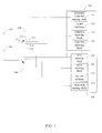
- FIG. 1 is a structural block diagram illustrating a radio frequency (RF) structure of a mobile terminal in a first preferred embodiment of the present invention.
- RF radio frequency
- the RF structure of the mobile terminal in the present invention includes frequency band modules 310 and 320, antennas 101 and 102 and antenna switches 110 and 120.
- the frequency band module 310 includes the frequency band sets 311, 312, 313 and 314, and the frequency band set 311 is a GSM850 and GSM900 emitting block, the frequency band set 312 is a 3G RF second block, the frequency band set 313 is a GSM850 receiving block, and the frequency band set 314 is a GSM900 receiving block.
- the frequency band module 320 is the second frequency band module, such as a high frequency band module and includes frequency band sets 321, 322, 323 and 324.
- the frequency band set 321 is a Personal Communications Service (PCS) receiving block
- the frequency band set 322 is a Digital Cellular System (DCS) receiving block
- the frequency band set 323 is a 3G RF first block
- the frequency band set 324 is DCS, PCS emitting block.
- the low frequency band module, the high frequency band module and the frequency band set thereof are stated herein for example, and the frequency bands can be arbitrarily divided into different frequency modules in accordance with the frequency band properties. It is not to limit that only two frequency band modules in the previous description can be used and the frequency band sets in each of the frequency band modules can be adjusted in accordance with the practical implement in the present invention.
- the two antennas are provided to receive or emit multiple RF signals accordingly.
- the antenna 101 is a low frequency band antenna which matches the frequency band module 310 and the antenna 102 is a high frequency band antenna which matches the frequency band module 320.
- the antenna switch 110 connects the receiving and emitting signals of the low frequency band module 310 with the antenna 101 and the antenna switch 120 connects the receiving and emitting signals of the high frequency band module 320 with the antenna102.
- the antenna switches 110 and 120 are many-to-one switches.
- the practical connection manner of the antenna switch 110 is: a first end 111 of the antenna switch 110 is connected to the antenna 101, and a second end of the antenna switch 110 includes four optional ends 112, 113, 114 and 115 and the four optional ends 112, 113, 114, and 115 are respectively connected to the frequency band sets 311, 312, 313 and 314.
- the receiving and emitting signals of the low frequency band module 3 10 are fed to the antenna by the connection between the first end 111 of the antenna switch 110 and the optional ends 112, 113, 114 and 115.
- the connective method of the antenna switch 120 is the same as the antenna switch 110 and the detail description thereof is omitted herein.
- the signals with the frequency band modules 310 and 320 which include different frequency band properties, are respectively passing through the antenna switch 110 and 120 to the corresponding antennas 101 and 102.
- the antennas 101 or 102 can be optionally selected to avoid the mutual interruption generated when the antennas 101 and 102 are used at the same time. Therefore, it is optimizing to match the multiple antennas structure to reduce cost and enhance the RF performance.
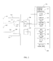
- FIG. 2 is a structural block diagram illustrating the RF structure of the mobile terminal in another embodiment of the present invention.
- the difference between the RF structure of the mobile terminal in the second embodiment and the RF structure of the mobile terminal in the first embodiment of FIG. 1 is the design of the antenna switch.
- the RF structure of the mobile terminal includes: frequency band modules 310 and 320, antennas 101 and 102, first antenna switches 210 and 220, and second antenna switches 230 and 240.
- the first antenna switches 210 and 220 are four-to-one switches.
- the first antenna switch 210 is as example to describe the connection method of the first antenna switch.
- a first end 211 of the first antenna switch 210 is connected to the antenna 101.
- a second end of the first antenna switch 210 includes four optional ends 212, 213, 214 and 215.
- the optional ends 212 and 213 are respectively connected to the frequency band sets 311 and 312, the optional end 214 is connected to an end 231 of the second antenna switch 230 and the optional end 215 is floating.
- the connective method of the first antenna switch 220 is the same as the first antenna switch 210 and the detail description thereof is omitted herein.
- the second antenna switches 230 and 240 are two-to-one switches.
- the second antenna switch 230 is as example to describe the connective method of the second antenna switch.
- a first end 231 of the second antenna switch 230 is connected to the optional end 214 of the first antenna switch 210.
- a second end of the second antenna switch 230 includes two optional ends 232 and 233.
- the optional ends 232 and 233 are respectively connected to the frequency band sets 313 and 314.
- the connective method of the second antenna switch 240 is the same as the second antenna switch 230 and the detail description thereof is omitted herein.
- the antennas 101 or 102 can be optionally selected to avoid the mutual interruption generated when the antenna 101 and 102 are used at the same time.
- the first antenna switches 210 and 220 in the present embodiment are configured to operate in coordination with the second antenna switches 230 and 240 to minimize the volume of the RF structure of the mobile terminal in the present invention.
- FIG. 3 is a structural view illustrating the mobile terminal in the present invention.
- the mobile terminal includes a main body 31 and an RF structure 32 provided in the embodiment of the present invention.
- the main body 31 of the mobile terminal is connected to the RF structure 32 of the mobile terminal, and the RF signal emitting and receiving is performed by the RF structure 32 of the mobile terminal so as to communicate with external environment.
- the mobile terminal in the present invention can connect to the terminal devices, such as cellular phone, netbook and so on, in any network protocols.
- the RF structure of the mobile terminal provided in the present invention can optimize the design to match the multiple antennas to satisfy the requirement (such as multiple frequency bands, small volume, and low cost) of the RF structure of the mobile terminal to enhance the RF performance.
Landscapes
- Engineering & Computer Science (AREA)
- Computer Networks & Wireless Communication (AREA)
- Signal Processing (AREA)
- Transceivers (AREA)
- Variable-Direction Aerials And Aerial Arrays (AREA)
- Mobile Radio Communication Systems (AREA)
Abstract
Description
- The present invention relates to a field of mobile terminal, and more particularly relates to a mobile terminal with multiple antennas and a radio frequency structure thereof.
- Currently, the mobile telecommunication is in a third generation (3G) era, and there are various 3G mobile terminals released in the market. However, there are still ample users using a second generation (2G) telecommunication network. Especially in countries or regions implementing Global System for Mobile communications (GSM) and Wideband Code Division Multiple Access (WCDMA) progressive path, 2G network users still occupied a very large portion. Therefore, most of the mobile terminals are adopting 2G and 3G dual modes. The features of the 2G and 3G dual modes are to support multiple frequency bands, such as four frequency bands in GSM (GSM850, GSM900, Digital Cellular System (DCS) and Personal Communications Service (PCS)) and two frequency bands in WCDMA dual band (BC1/BC8 or BC2/BC5). This design pattern is a significant trial for designing terminal antennas.
- Because the tendency of the design in the current mobile terminal is light and thin, the supporting frequency bands are increased but the space for the terminal antenna is smaller and smaller. Even a speaker, a telephone receiver and a camera are put in the space of the antenna. Because the feature techniques, such as the height of the antenna and the open space of the antenna, are restricted, the performance of the mobile terminal antenna is seriously decreased. It is difficult for the single antenna structure used in the current mobile terminal to satisfy the requirement of the multiple frequency bands.
- Therefore, a need is arisen to provide a mobile terminal and a radio frequency (RF) structure thereof optimizing to match the multiple antennas structure so as to satisfy the requirements of multiple frequency bands, smaller sizes, good RF performance and lower costs for the modern RF structure of the mobile terminal.
- The present invention solves the technical problem by providing a mobile terminal and a radio frequency structure thereof optimizing to match the multiple antennas structure so as to reduce cost and enhance RF performance.
- An RF structure of the mobile terminal provided in the present invention includes: a plurality of frequency band modules having different frequency band properties, respectively, each of the frequency band modules includes a plurality of frequency band sets, and each of the frequency band sets includes a plurality of frequency bands; antennas are respectively configured to match the frequency band modules; antenna switches are configured to connect a plurality of emitting and receiving signals of the frequency band module with the antennas; wherein the frequency band modules include a first frequency band module and a second frequency band module, and the antennas include a first frequency band antenna corresponding to the first frequency band module and a second frequency band antenna corresponding to the second frequency band module.
- An RF structure of the mobile terminal provided in the present invention includes: a plurality of frequency band modules having different frequency band properties, respectively; a plurality of are antennas respectively configured to match the frequency band modules; and antenna switches are configured to connect a plurality of emitting and receiving signals of the frequency band module with the antennas.
- In accordance with one preferred embodiment of the present invention, each of the frequency band modules includes a plurality of frequency band sets and each of the frequency band sets includes a plurality of frequency bands.
- In accordance with one preferred embodiment of the present invention, the frequency band modules include a first frequency band module and a second frequency band module, and the antennas include a first frequency band antenna corresponding to the first frequency band module and a second frequency band antenna corresponding to the second frequency band module.
- In accordance with one preferred embodiment of the present invention, the first frequency band module is a high frequency band module and the second frequency band module is a low frequency band module.
- In accordance with one preferred embodiment of the present invention, a first end of the antenna switch is connected to the antenna and a second end of the antenna switch is connected to the frequency band set or is floating.
- In accordance with one preferred embodiment of the present invention, the antenna switch is a many-to-one switch.
- In accordance with one preferred embodiment of the present invention, an optional end of the many-to-one switch is floating.
- In accordance with one preferred embodiment of the present invention, the antenna switch includes a first antenna switch and a second antenna switch, and a first end of the first antenna switch is connected to the antenna and a second end of the first antenna switch is connected to the frequency band set or a first end of the second antenna switch or is floating, and a second end of the second antenna switch is connected to the frequency band sets.
- A mobile terminal provided in the present invention and the mobile terminal includes an RF structure and the RF structure of the mobile terminal includes: a plurality of frequency band modules having different frequency band properties, respectively; a plurality of antennas are respectively configured to match the frequency band modules; and a plurality of antenna switches are configured to connect a plurality of emitting and receiving signals of the frequency band modules with the antenna.
- In accordance with one preferred embodiment of the present invention, each of the frequency band modules includes a plurality of frequency band sets and each of the frequency band sets includes a plurality of frequency bands.
- In accordance with one preferred embodiment of the present invention, the frequency band modules include a first frequency band module and a second frequency band module, and the antennas include a first frequency band antenna corresponding to the first frequency band module and a second frequency band antenna corresponding to the second frequency band module.
- In accordance with one preferred embodiment of the present invention, the first frequency band module is a high frequency band module and the second frequency band module is a low frequency band module.
- In accordance with one preferred embodiment of the present invention, a first end of the antenna switch is connected to the antenna and a second end of the antenna switch is connected to the frequency band set or floating.
- In accordance with one preferred embodiment of the present invention, the antenna switch is a many-to-one switch.
- In accordance with one preferred embodiment of the present invention, an optional end of the many-to-one switch is floating.
- In accordance with one preferred embodiment of the present invention, the antenna switch includes a first antenna switch and a second antenna switch, and a first end of the first antenna switch is connected to the antenna and a second end of the first antenna switch is connected to the frequency band set or a first end of the second antenna switch or floating, and a second end of the second antenna switch is connected to the frequency band sets.
- In accordance with one preferred embodiment of the present invention, the mobile terminal is a cellular phone or a netbook.
- According to the description above, the RF structure of the mobile terminal provided in the present invention satisfies the requirement (such as multiple frequency bands, small dimension, and low cost) of the RF structure of the mobile terminal and also enhances the RF performance.
- The above and other aspects, features and advantages of certain exemplary embodiments of the present invention will be more apparent from the following description taken in conjunction with the accompanying drawing. So that those having ordinary skill in the art to which the subject invention pertains will more readily understand how to employ the subject invention, preferred embodiments thereof will be described in detail herein below with reference to the drawings, wherein:
-
FIG. 1 is a structural block diagram illustrating a radio frequency (RF) structure of a mobile terminal in a first preferred embodiment of the present invention; -
FIG. 2 is a structural block diagram illustrating the RF structure of the mobile terminal in a second preferred embodiment of the present invention; and -
FIG. 3 is a structural view illustrating the mobile terminal in the embodiment of the present invention. - In the following detailed description of the preferred embodiments, reference is made to the accompanying drawings which form a part hereof, and as shown by way of illustration specific embodiments in which the invention may be practiced. The directional terminology is used for purposes of illustration and is in no way limiting the present invention.
- The present invention is to provide a mobile terminal and a radio frequency structure thereof. Practically, the radio frequency structure of the mobile terminal in the present invention is designed in accordance with a scheme of multiple antennas. All of the frequency bands are divided into N portions in accordance with the properties of the frequency bands, and the mobile terminal is accordingly designed to have N antennas, and N antenna switches are allocated. The frequency bands with different frequency band properties are fed to the different antennas through the antenna switches, and N is an integral, which is equal to or greater than 2.
-
FIG. 1 is a structural block diagram illustrating a radio frequency (RF) structure of a mobile terminal in a first preferred embodiment of the present invention. - As shown in
FIG. 1 , in the embodiment of the present invention, the most frequently used frequency bands: WCDMA BC1/BC8 and four frequency bands of GSM are described herein as examples. The RF structure of the mobile terminal in the present invention includesfrequency band modules antennas antenna switches - Specifically, in the embodiment of the present invention, all of the frequency bands are divided into two portions in accordance with the frequency band properties. So there are a high
frequency band module 310 and a lowfrequency band module 320. Each of the frequency band modules includes a plurality of frequency band sets, each of the frequency band sets includes a plurality of frequency bands, and each of the frequency bands includes a plurality of frequency points. Practically, thefrequency band module 310 includes thefrequency band sets frequency band set 311 is a GSM850 and GSM900 emitting block, the frequency band set 312 is a 3G RF second block, thefrequency band set 313 is a GSM850 receiving block, and thefrequency band set 314 is a GSM900 receiving block. Thefrequency band module 320 is the second frequency band module, such as a high frequency band module and includesfrequency band sets frequency band set 322 is a Digital Cellular System (DCS) receiving block, thefrequency band set 323 is a 3G RF first block, and the frequency band set 324 is DCS, PCS emitting block. It should be noted that the low frequency band module, the high frequency band module and the frequency band set thereof are stated herein for example, and the frequency bands can be arbitrarily divided into different frequency modules in accordance with the frequency band properties. It is not to limit that only two frequency band modules in the previous description can be used and the frequency band sets in each of the frequency band modules can be adjusted in accordance with the practical implement in the present invention. - In the embodiment of the present invention, the two antennas are provided to receive or emit multiple RF signals accordingly. The
antenna 101 is a low frequency band antenna which matches thefrequency band module 310 and theantenna 102 is a high frequency band antenna which matches thefrequency band module 320. - The
antenna switch 110 connects the receiving and emitting signals of the lowfrequency band module 310 with theantenna 101 and theantenna switch 120 connects the receiving and emitting signals of the highfrequency band module 320 with the antenna102. The antenna switches 110 and 120 are many-to-one switches. The practical connection manner of theantenna switch 110 is: afirst end 111 of theantenna switch 110 is connected to theantenna 101, and a second end of theantenna switch 110 includes fouroptional ends optional ends frequency band sets first end 111 of theantenna switch 110 and theoptional ends - The connective method of the
antenna switch 120 is the same as theantenna switch 110 and the detail description thereof is omitted herein. - The signals with the
frequency band modules antenna switch antennas antennas antennas -
FIG. 2 is a structural block diagram illustrating the RF structure of the mobile terminal in another embodiment of the present invention. As shown inFIG. 2 , the difference between the RF structure of the mobile terminal in the second embodiment and the RF structure of the mobile terminal in the first embodiment ofFIG. 1 is the design of the antenna switch. Specifically, the RF structure of the mobile terminal includes:frequency band modules antennas first antenna switches second antenna switches - The
first antenna switches first antenna switch 210 is as example to describe the connection method of the first antenna switch. Afirst end 211 of thefirst antenna switch 210 is connected to theantenna 101. A second end of thefirst antenna switch 210 includes fouroptional ends optional end 214 is connected to anend 231 of thesecond antenna switch 230 and theoptional end 215 is floating. The connective method of thefirst antenna switch 220 is the same as thefirst antenna switch 210 and the detail description thereof is omitted herein. - The
second antenna switches second antenna switch 230 is as example to describe the connective method of the second antenna switch. Afirst end 231 of thesecond antenna switch 230 is connected to theoptional end 214 of thefirst antenna switch 210. A second end of thesecond antenna switch 230 includes twooptional ends second antenna switch 240 is the same as thesecond antenna switch 230 and the detail description thereof is omitted herein. - By the connection between the
first end 211 of thefirst antenna switch 210 and the floatingend 215 or the connection between thefirst end 221 of thesecond antenna switch 220 and the floatingend 225, theantennas antenna - According to the description above, in the embodiment of the present invention, because the
GSM850 receiving block 313 and theGSM900 receiving block 314 are merged together and thePCS receiving block 321 and theDCS receiving block 322 are merged together, only two single pole triple throw (SP3T) switches are required in the whole RF structure and the space and the cost of the RF structure is further optimized. - In addition, in accordance with the condition that the number of the supporting frequency band sets is the same, the
first antenna switches second antenna switches - Please refer to
FIG. 3 , which is a structural view illustrating the mobile terminal in the present invention. The mobile terminal includes amain body 31 and anRF structure 32 provided in the embodiment of the present invention. Themain body 31 of the mobile terminal is connected to theRF structure 32 of the mobile terminal, and the RF signal emitting and receiving is performed by theRF structure 32 of the mobile terminal so as to communicate with external environment. The mobile terminal in the present invention can connect to the terminal devices, such as cellular phone, netbook and so on, in any network protocols. - According to the description above, the RF structure of the mobile terminal provided in the present invention can optimize the design to match the multiple antennas to satisfy the requirement (such as multiple frequency bands, small volume, and low cost) of the RF structure of the mobile terminal to enhance the RF performance.
- As described above, the present invention has been described with preferred embodiments thereof and it is understood that many changes and modifications to the described embodiments can be carried out without departing from the scope and the spirit of the invention that is intended to be limited only by the appended claims.
Claims (18)
- A radio frequency (RF) structure of a mobile terminal, characterized in that the RF structure of the mobile terminal comprises:a plurality of frequency band modules having different frequency band properties, respectively, each of the frequency band modules including a plurality of frequency band sets and each of the frequency band sets includes a plurality of frequency bands;a plurality of antennas respectively configured to match the frequency band modules;a plurality of antenna switches configured to connect a plurality of emitting and receiving signals of the frequency band module with the antenna;wherein the frequency band modules include a first frequency band module and a second frequency band module, and the antennas include a first frequency band antenna matching the first frequency band module and a second frequency band antenna matching the second frequency band module.
- An RF structure of the mobile terminal, characterized in that the RF structure of the mobile terminal comprises:a plurality of frequency band modules having different frequency band properties, respectively;a plurality of antennas respectively configured to match the frequency band modules;a plurality of antenna switches configured to connect a plurality of emitting and receiving signals of the frequency band module with the antennas.
- The RF structure of the mobile terminal according to claim 2, characterized in that each of the frequency band modules include a plurality of frequency band sets and each of the frequency band sets include a plurality of frequency bands.
- The RF structure of the mobile terminal according to claim 2, characterized in that the frequency band modules include a first frequency band module and a second frequency band module, and the antennas include a first frequency band antenna corresponding to the first frequency band module and a second frequency band antenna corresponding to the second frequency band module.
- The RF structure of the mobile terminal according to claim 4, characterized in that the first frequency band module is a high frequency band module and the second frequency band module is a low frequency band module.
- The RF structure of the mobile terminal according to claim 3, characterized in that a first end of the antenna switch is connected to the antenna and a second end of the antenna switch is connected to the frequency band set or is floating.
- The RF structure of the mobile terminal according to claim 6, characterized in that the antenna switch is a many-to-one switch.
- The RF structure of the mobile terminal according to claim 7, characterized in that an optional end of the many-to-one switch is floating.
- The RF structure of the mobile terminal according to claim 2, characterized in that the antenna switches include a first antenna switch and a second antenna switch, a first end of the first antenna switch is connected to the antenna and a second end of the first antenna switch is connected to the frequency band set or a first end of the second antenna switch or is floating, and a second end of the second antenna switch is connected to the frequency band sets.
- A mobile terminal, characterized in that the mobile terminal comprises an RF structure and the RF structure of the mobile terminal comprises:a plurality of frequency band modules having different frequency band properties, respectively;a plurality of antennas respectively configured to match the frequency band modules;a plurality of antenna switches configured to connect a plurality of emitting and receiving signals of the frequency band module with the antennas.
- The mobile terminal according to claim 10, characterized in that each of the frequency band modules includes a plurality of frequency band sets and each of the frequency band sets includes a plurality of frequency bands.
- The mobile terminal according to claim 10, characterized in that the frequency band modules include a first frequency band module and a second frequency band module, and the antennas include a first frequency band antenna matching the first frequency band module and a second frequency band antenna matching the second frequency band module.
- The mobile terminal according to claim 12, characterized in that the first frequency band module is a high frequency band module and the second frequency band module is a low frequency band module.
- The mobile terminal according to claim 11, characterized in that a first end of the antenna switch is connected to the antenna and a second end of the antenna switch is connected to the frequency band set or floating.
- The mobile terminal according to claim 14, characterized in that the antenna switch is a many-to-one switch.
- The mobile terminal according to claim 15, characterized in that an optional end of the many-to-one switch is floating.
- The mobile terminal according to claim 10, characterized in that the antenna switches include a first antenna switch and a second antenna switch, and a first end of the first antenna switch is connected to the antenna and a second end of the first antenna switch is connected to the frequency band set or a first end of the second antenna switch or is floating, and a second end of the second antenna switch is connected to the frequency band sets.
- The mobile terminal according to claim 10, characterized in that the mobile terminal is a cellular phone or a netbook.
Applications Claiming Priority (2)
| Application Number | Priority Date | Filing Date | Title |
|---|---|---|---|
| CN2010105707082A CN102006678B (en) | 2010-12-02 | 2010-12-02 | Mobile terminal and radio frequency framework thereof |
| PCT/CN2011/080701 WO2012071948A1 (en) | 2010-12-02 | 2011-10-12 | Mobile terminal and radio frequency structure thereof |
Publications (3)
| Publication Number | Publication Date |
|---|---|
| EP2648474A1 true EP2648474A1 (en) | 2013-10-09 |
| EP2648474A4 EP2648474A4 (en) | 2016-11-23 |
| EP2648474B1 EP2648474B1 (en) | 2018-11-21 |
Family
ID=43813638
Family Applications (1)
| Application Number | Title | Priority Date | Filing Date |
|---|---|---|---|
| EP11845327.3A Active EP2648474B1 (en) | 2010-12-02 | 2011-10-12 | Mobile terminal and radio frequency structure thereof |
Country Status (5)
| Country | Link |
|---|---|
| US (1) | US20130237165A1 (en) |
| EP (1) | EP2648474B1 (en) |
| CN (1) | CN102006678B (en) |
| ES (1) | ES2711650T3 (en) |
| WO (1) | WO2012071948A1 (en) |
Cited By (1)
| Publication number | Priority date | Publication date | Assignee | Title |
|---|---|---|---|---|
| WO2017211024A1 (en) * | 2016-06-08 | 2017-12-14 | 中兴通讯股份有限公司 | Multi-antenna system of terminal device, and signal transmission method for terminal device |
Families Citing this family (5)
| Publication number | Priority date | Publication date | Assignee | Title |
|---|---|---|---|---|
| CN102006678B (en) * | 2010-12-02 | 2013-11-20 | 惠州Tcl移动通信有限公司 | Mobile terminal and radio frequency framework thereof |
| CN102185950B (en) * | 2011-06-03 | 2013-12-18 | 惠州Tcl移动通信有限公司 | Radio-frequency testing device and radio-frequency testing method for multi-antenna handset |
| CN105827258B (en) * | 2016-05-09 | 2019-03-08 | 中国电子科技集团公司第三十八研究所 | A multi-channel receiving system |
| CN108966314A (en) * | 2017-05-26 | 2018-12-07 | 中国移动通信有限公司研究院 | A kind of network search method and device |
| CN115102559B (en) * | 2022-06-07 | 2023-11-10 | Oppo广东移动通信有限公司 | Radio frequency PA Mid device, radio frequency system and communication equipment |
Family Cites Families (14)
| Publication number | Priority date | Publication date | Assignee | Title |
|---|---|---|---|---|
| US6560443B1 (en) * | 1999-05-28 | 2003-05-06 | Nokia Corporation | Antenna sharing switching circuitry for multi-transceiver mobile terminal and method therefor |
| EP1160911A1 (en) * | 2000-05-29 | 2001-12-05 | Sony International (Europe) GmbH | Additional antenna RF switch in a mobile terminal for a wireless telecommunication system |
| US7187945B2 (en) * | 2004-04-30 | 2007-03-06 | Nokia Corporation | Versatile antenna switch architecture |
| US7251499B2 (en) * | 2004-06-18 | 2007-07-31 | Nokia Corporation | Method and device for selecting between internal and external antennas |
| US20060063494A1 (en) * | 2004-10-04 | 2006-03-23 | Xiangdon Zhang | Remote front-end for a multi-antenna station |
| CN100428643C (en) * | 2004-10-13 | 2008-10-22 | 英华达(上海)电子有限公司 | antenna module |
| US7383032B2 (en) * | 2004-12-02 | 2008-06-03 | Avago Technologies Wireless Ip Pte Ltd | Cellular phone and method for receiving and transmitting signals of different frequency bands |
| US7512388B2 (en) * | 2005-09-22 | 2009-03-31 | Skyworks Solutions, Inc. | Multiband or multimode front end antenna switch |
| US8150454B2 (en) * | 2005-12-19 | 2012-04-03 | Sony Ericsson Mobile Communications Ab | System and method for implementing antenna diversity |
| US7551146B2 (en) * | 2007-03-30 | 2009-06-23 | Intel Corporation | Configurable antenna for mixed wireless networks |
| CN201388196Y (en) * | 2009-03-13 | 2010-01-20 | 中兴通讯股份有限公司 | Mobile Terminal Realizing Multi-Band Matching of Antennas |
| CN101640949B (en) * | 2009-06-29 | 2012-07-25 | 惠州Tcl移动通信有限公司 | Multi-antenna wireless transceiving device |
| CN201919161U (en) * | 2010-12-02 | 2011-08-03 | 惠州Tcl移动通信有限公司 | Mobile terminal and radio frequency framework thereof |
| CN102006678B (en) * | 2010-12-02 | 2013-11-20 | 惠州Tcl移动通信有限公司 | Mobile terminal and radio frequency framework thereof |
-
2010
- 2010-12-02 CN CN2010105707082A patent/CN102006678B/en not_active Expired - Fee Related
-
2011
- 2011-10-12 ES ES11845327T patent/ES2711650T3/en active Active
- 2011-10-12 EP EP11845327.3A patent/EP2648474B1/en active Active
- 2011-10-12 WO PCT/CN2011/080701 patent/WO2012071948A1/en not_active Ceased
- 2011-10-12 US US13/702,311 patent/US20130237165A1/en not_active Abandoned
Cited By (2)
| Publication number | Priority date | Publication date | Assignee | Title |
|---|---|---|---|---|
| WO2017211024A1 (en) * | 2016-06-08 | 2017-12-14 | 中兴通讯股份有限公司 | Multi-antenna system of terminal device, and signal transmission method for terminal device |
| CN107482303A (en) * | 2016-06-08 | 2017-12-15 | 中兴通讯股份有限公司 | Terminal device multiaerial system and terminal device method for transmitting signals |
Also Published As
| Publication number | Publication date |
|---|---|
| ES2711650T3 (en) | 2019-05-06 |
| EP2648474B1 (en) | 2018-11-21 |
| EP2648474A4 (en) | 2016-11-23 |
| CN102006678A (en) | 2011-04-06 |
| WO2012071948A1 (en) | 2012-06-07 |
| CN102006678B (en) | 2013-11-20 |
| US20130237165A1 (en) | 2013-09-12 |
Similar Documents
| Publication | Publication Date | Title |
|---|---|---|
| CN102185623B (en) | Mobile terminal and multi-antenna realizing method thereof | |
| US9002297B2 (en) | Mobile device and tunable antenna therein | |
| US9142879B2 (en) | Wireless electronic devices with a metal perimeter including a plurality of antennas | |
| US8907853B2 (en) | Wireless electronic devices with multiple curved antennas along an end portion, and related antenna systems | |
| EP2575208B1 (en) | Multi-band wireless terminal | |
| EP2735053B1 (en) | Multi-band wireless terminals with metal backplates and coupling feed elements, and related multi-band antenna systems | |
| US7439914B1 (en) | Antenna unit | |
| US20130237165A1 (en) | Mobile terminal and radio frequency structure threrof | |
| US20150002350A1 (en) | Wireless electronic devices including a variable tuning component | |
| US9368862B2 (en) | Wideband antenna and an electronic device including the same | |
| US10141632B2 (en) | Wireless electronic devices with metal perimeter portions including a plurality of antennas | |
| US8868126B2 (en) | Mobile apparatus with radio frequency architecture supporting simultaneous data and voice communications | |
| KR20100020233A (en) | Multi-band antenna by using switching | |
| US9231304B2 (en) | Wideband loop antenna and an electronic device including the same | |
| US20090312050A1 (en) | Multi-band mobile communication device | |
| US9077437B2 (en) | Front-end circuit | |
| CN201975511U (en) | Terminal antenna | |
| CN210006896U (en) | Metal frame antenna and terminal comprising same | |
| US20180342800A1 (en) | Electronic device | |
| US9214727B2 (en) | Multi-band antenna | |
| CN201919161U (en) | Mobile terminal and radio frequency framework thereof | |
| CN105449359A (en) | Antenna system, mobile terminal and communication method |
Legal Events
| Date | Code | Title | Description |
|---|---|---|---|
| PUAI | Public reference made under article 153(3) epc to a published international application that has entered the european phase |
Free format text: ORIGINAL CODE: 0009012 |
|
| 17P | Request for examination filed |
Effective date: 20121121 |
|
| AK | Designated contracting states |
Kind code of ref document: A1 Designated state(s): AL AT BE BG CH CY CZ DE DK EE ES FI FR GB GR HR HU IE IS IT LI LT LU LV MC MK MT NL NO PL PT RO RS SE SI SK SM TR |
|
| DAX | Request for extension of the european patent (deleted) | ||
| RA4 | Supplementary search report drawn up and despatched (corrected) |
Effective date: 20161021 |
|
| RIC1 | Information provided on ipc code assigned before grant |
Ipc: H04B 1/3827 20150101ALI20161017BHEP Ipc: H04W 88/02 20090101AFI20161017BHEP |
|
| RIC1 | Information provided on ipc code assigned before grant |
Ipc: H04B 1/3827 20150101ALI20180411BHEP Ipc: H04W 88/02 20090101AFI20180411BHEP |
|
| GRAP | Despatch of communication of intention to grant a patent |
Free format text: ORIGINAL CODE: EPIDOSNIGR1 |
|
| STAA | Information on the status of an ep patent application or granted ep patent |
Free format text: STATUS: GRANT OF PATENT IS INTENDED |
|
| INTG | Intention to grant announced |
Effective date: 20180528 |
|
| RAP1 | Party data changed (applicant data changed or rights of an application transferred) |
Owner name: HUIZHOU TCL MOBILE COMMUNICATION CO., LTD |
|
| GRAS | Grant fee paid |
Free format text: ORIGINAL CODE: EPIDOSNIGR3 |
|
| GRAA | (expected) grant |
Free format text: ORIGINAL CODE: 0009210 |
|
| STAA | Information on the status of an ep patent application or granted ep patent |
Free format text: STATUS: THE PATENT HAS BEEN GRANTED |
|
| AK | Designated contracting states |
Kind code of ref document: B1 Designated state(s): AL AT BE BG CH CY CZ DE DK EE ES FI FR GB GR HR HU IE IS IT LI LT LU LV MC MK MT NL NO PL PT RO RS SE SI SK SM TR |
|
| REG | Reference to a national code |
Ref country code: CH Ref legal event code: EP |
|
| REG | Reference to a national code |
Ref country code: IE Ref legal event code: FG4D |
|
| REG | Reference to a national code |
Ref country code: DE Ref legal event code: R096 Ref document number: 602011054185 Country of ref document: DE |
|
| REG | Reference to a national code |
Ref country code: AT Ref legal event code: REF Ref document number: 1069080 Country of ref document: AT Kind code of ref document: T Effective date: 20181215 |
|
| REG | Reference to a national code |
Ref country code: NL Ref legal event code: MP Effective date: 20181121 |
|
| REG | Reference to a national code |
Ref country code: AT Ref legal event code: MK05 Ref document number: 1069080 Country of ref document: AT Kind code of ref document: T Effective date: 20181121 |
|
| PG25 | Lapsed in a contracting state [announced via postgrant information from national office to epo] |
Ref country code: AT Free format text: LAPSE BECAUSE OF FAILURE TO SUBMIT A TRANSLATION OF THE DESCRIPTION OR TO PAY THE FEE WITHIN THE PRESCRIBED TIME-LIMIT Effective date: 20181121 Ref country code: NO Free format text: LAPSE BECAUSE OF FAILURE TO SUBMIT A TRANSLATION OF THE DESCRIPTION OR TO PAY THE FEE WITHIN THE PRESCRIBED TIME-LIMIT Effective date: 20190221 Ref country code: FI Free format text: LAPSE BECAUSE OF FAILURE TO SUBMIT A TRANSLATION OF THE DESCRIPTION OR TO PAY THE FEE WITHIN THE PRESCRIBED TIME-LIMIT Effective date: 20181121 Ref country code: BG Free format text: LAPSE BECAUSE OF FAILURE TO SUBMIT A TRANSLATION OF THE DESCRIPTION OR TO PAY THE FEE WITHIN THE PRESCRIBED TIME-LIMIT Effective date: 20190221 Ref country code: IS Free format text: LAPSE BECAUSE OF FAILURE TO SUBMIT A TRANSLATION OF THE DESCRIPTION OR TO PAY THE FEE WITHIN THE PRESCRIBED TIME-LIMIT Effective date: 20190321 Ref country code: LT Free format text: LAPSE BECAUSE OF FAILURE TO SUBMIT A TRANSLATION OF THE DESCRIPTION OR TO PAY THE FEE WITHIN THE PRESCRIBED TIME-LIMIT Effective date: 20181121 Ref country code: HR Free format text: LAPSE BECAUSE OF FAILURE TO SUBMIT A TRANSLATION OF THE DESCRIPTION OR TO PAY THE FEE WITHIN THE PRESCRIBED TIME-LIMIT Effective date: 20181121 Ref country code: LV Free format text: LAPSE BECAUSE OF FAILURE TO SUBMIT A TRANSLATION OF THE DESCRIPTION OR TO PAY THE FEE WITHIN THE PRESCRIBED TIME-LIMIT Effective date: 20181121 |
|
| REG | Reference to a national code |
Ref country code: ES Ref legal event code: FG2A Ref document number: 2711650 Country of ref document: ES Kind code of ref document: T3 Effective date: 20190506 |
|
| PG25 | Lapsed in a contracting state [announced via postgrant information from national office to epo] |
Ref country code: NL Free format text: LAPSE BECAUSE OF FAILURE TO SUBMIT A TRANSLATION OF THE DESCRIPTION OR TO PAY THE FEE WITHIN THE PRESCRIBED TIME-LIMIT Effective date: 20181121 Ref country code: SE Free format text: LAPSE BECAUSE OF FAILURE TO SUBMIT A TRANSLATION OF THE DESCRIPTION OR TO PAY THE FEE WITHIN THE PRESCRIBED TIME-LIMIT Effective date: 20181121 Ref country code: RS Free format text: LAPSE BECAUSE OF FAILURE TO SUBMIT A TRANSLATION OF THE DESCRIPTION OR TO PAY THE FEE WITHIN THE PRESCRIBED TIME-LIMIT Effective date: 20181121 Ref country code: AL Free format text: LAPSE BECAUSE OF FAILURE TO SUBMIT A TRANSLATION OF THE DESCRIPTION OR TO PAY THE FEE WITHIN THE PRESCRIBED TIME-LIMIT Effective date: 20181121 Ref country code: PT Free format text: LAPSE BECAUSE OF FAILURE TO SUBMIT A TRANSLATION OF THE DESCRIPTION OR TO PAY THE FEE WITHIN THE PRESCRIBED TIME-LIMIT Effective date: 20190321 Ref country code: GR Free format text: LAPSE BECAUSE OF FAILURE TO SUBMIT A TRANSLATION OF THE DESCRIPTION OR TO PAY THE FEE WITHIN THE PRESCRIBED TIME-LIMIT Effective date: 20190222 |
|
| PG25 | Lapsed in a contracting state [announced via postgrant information from national office to epo] |
Ref country code: DK Free format text: LAPSE BECAUSE OF FAILURE TO SUBMIT A TRANSLATION OF THE DESCRIPTION OR TO PAY THE FEE WITHIN THE PRESCRIBED TIME-LIMIT Effective date: 20181121 Ref country code: PL Free format text: LAPSE BECAUSE OF FAILURE TO SUBMIT A TRANSLATION OF THE DESCRIPTION OR TO PAY THE FEE WITHIN THE PRESCRIBED TIME-LIMIT Effective date: 20181121 Ref country code: CZ Free format text: LAPSE BECAUSE OF FAILURE TO SUBMIT A TRANSLATION OF THE DESCRIPTION OR TO PAY THE FEE WITHIN THE PRESCRIBED TIME-LIMIT Effective date: 20181121 |
|
| REG | Reference to a national code |
Ref country code: DE Ref legal event code: R097 Ref document number: 602011054185 Country of ref document: DE |
|
| PG25 | Lapsed in a contracting state [announced via postgrant information from national office to epo] |
Ref country code: SK Free format text: LAPSE BECAUSE OF FAILURE TO SUBMIT A TRANSLATION OF THE DESCRIPTION OR TO PAY THE FEE WITHIN THE PRESCRIBED TIME-LIMIT Effective date: 20181121 Ref country code: EE Free format text: LAPSE BECAUSE OF FAILURE TO SUBMIT A TRANSLATION OF THE DESCRIPTION OR TO PAY THE FEE WITHIN THE PRESCRIBED TIME-LIMIT Effective date: 20181121 Ref country code: SM Free format text: LAPSE BECAUSE OF FAILURE TO SUBMIT A TRANSLATION OF THE DESCRIPTION OR TO PAY THE FEE WITHIN THE PRESCRIBED TIME-LIMIT Effective date: 20181121 Ref country code: RO Free format text: LAPSE BECAUSE OF FAILURE TO SUBMIT A TRANSLATION OF THE DESCRIPTION OR TO PAY THE FEE WITHIN THE PRESCRIBED TIME-LIMIT Effective date: 20181121 |
|
| PLBE | No opposition filed within time limit |
Free format text: ORIGINAL CODE: 0009261 |
|
| STAA | Information on the status of an ep patent application or granted ep patent |
Free format text: STATUS: NO OPPOSITION FILED WITHIN TIME LIMIT |
|
| 26N | No opposition filed |
Effective date: 20190822 |
|
| PG25 | Lapsed in a contracting state [announced via postgrant information from national office to epo] |
Ref country code: SI Free format text: LAPSE BECAUSE OF FAILURE TO SUBMIT A TRANSLATION OF THE DESCRIPTION OR TO PAY THE FEE WITHIN THE PRESCRIBED TIME-LIMIT Effective date: 20181121 |
|
| PG25 | Lapsed in a contracting state [announced via postgrant information from national office to epo] |
Ref country code: TR Free format text: LAPSE BECAUSE OF FAILURE TO SUBMIT A TRANSLATION OF THE DESCRIPTION OR TO PAY THE FEE WITHIN THE PRESCRIBED TIME-LIMIT Effective date: 20181121 |
|
| PG25 | Lapsed in a contracting state [announced via postgrant information from national office to epo] |
Ref country code: MC Free format text: LAPSE BECAUSE OF FAILURE TO SUBMIT A TRANSLATION OF THE DESCRIPTION OR TO PAY THE FEE WITHIN THE PRESCRIBED TIME-LIMIT Effective date: 20181121 |
|
| REG | Reference to a national code |
Ref country code: CH Ref legal event code: PL |
|
| PG25 | Lapsed in a contracting state [announced via postgrant information from national office to epo] |
Ref country code: CH Free format text: LAPSE BECAUSE OF NON-PAYMENT OF DUE FEES Effective date: 20191031 Ref country code: LU Free format text: LAPSE BECAUSE OF NON-PAYMENT OF DUE FEES Effective date: 20191012 Ref country code: LI Free format text: LAPSE BECAUSE OF NON-PAYMENT OF DUE FEES Effective date: 20191031 |
|
| REG | Reference to a national code |
Ref country code: BE Ref legal event code: MM Effective date: 20191031 |
|
| PG25 | Lapsed in a contracting state [announced via postgrant information from national office to epo] |
Ref country code: BE Free format text: LAPSE BECAUSE OF NON-PAYMENT OF DUE FEES Effective date: 20191031 |
|
| PG25 | Lapsed in a contracting state [announced via postgrant information from national office to epo] |
Ref country code: IE Free format text: LAPSE BECAUSE OF NON-PAYMENT OF DUE FEES Effective date: 20191012 |
|
| PG25 | Lapsed in a contracting state [announced via postgrant information from national office to epo] |
Ref country code: CY Free format text: LAPSE BECAUSE OF FAILURE TO SUBMIT A TRANSLATION OF THE DESCRIPTION OR TO PAY THE FEE WITHIN THE PRESCRIBED TIME-LIMIT Effective date: 20181121 |
|
| PG25 | Lapsed in a contracting state [announced via postgrant information from national office to epo] |
Ref country code: HU Free format text: LAPSE BECAUSE OF FAILURE TO SUBMIT A TRANSLATION OF THE DESCRIPTION OR TO PAY THE FEE WITHIN THE PRESCRIBED TIME-LIMIT; INVALID AB INITIO Effective date: 20111012 Ref country code: MT Free format text: LAPSE BECAUSE OF FAILURE TO SUBMIT A TRANSLATION OF THE DESCRIPTION OR TO PAY THE FEE WITHIN THE PRESCRIBED TIME-LIMIT Effective date: 20181121 |
|
| PG25 | Lapsed in a contracting state [announced via postgrant information from national office to epo] |
Ref country code: MK Free format text: LAPSE BECAUSE OF FAILURE TO SUBMIT A TRANSLATION OF THE DESCRIPTION OR TO PAY THE FEE WITHIN THE PRESCRIBED TIME-LIMIT Effective date: 20181121 |
|
| P01 | Opt-out of the competence of the unified patent court (upc) registered |
Effective date: 20230530 |
|
| PGFP | Annual fee paid to national office [announced via postgrant information from national office to epo] |
Ref country code: DE Payment date: 20251021 Year of fee payment: 15 |
|
| PGFP | Annual fee paid to national office [announced via postgrant information from national office to epo] |
Ref country code: GB Payment date: 20251022 Year of fee payment: 15 |
|
| PGFP | Annual fee paid to national office [announced via postgrant information from national office to epo] |
Ref country code: IT Payment date: 20251024 Year of fee payment: 15 |
|
| PGFP | Annual fee paid to national office [announced via postgrant information from national office to epo] |
Ref country code: FR Payment date: 20251030 Year of fee payment: 15 |
|
| PGFP | Annual fee paid to national office [announced via postgrant information from national office to epo] |
Ref country code: ES Payment date: 20251210 Year of fee payment: 15 |