EP2648316A1 - Rotor arrangement - Google Patents
Rotor arrangement Download PDFInfo
- Publication number
- EP2648316A1 EP2648316A1 EP12162964.6A EP12162964A EP2648316A1 EP 2648316 A1 EP2648316 A1 EP 2648316A1 EP 12162964 A EP12162964 A EP 12162964A EP 2648316 A1 EP2648316 A1 EP 2648316A1
- Authority
- EP
- European Patent Office
- Prior art keywords
- spacer element
- rotor
- rotor arrangement
- generator
- base area
- Prior art date
- Legal status (The legal status is an assumption and is not a legal conclusion. Google has not performed a legal analysis and makes no representation as to the accuracy of the status listed.)
- Granted
Links
Images

Classifications
-
- H—ELECTRICITY
- H02—GENERATION; CONVERSION OR DISTRIBUTION OF ELECTRIC POWER
- H02K—DYNAMO-ELECTRIC MACHINES
- H02K9/00—Arrangements for cooling or ventilating
- H02K9/02—Arrangements for cooling or ventilating by ambient air flowing through the machine
-
- H—ELECTRICITY
- H02—GENERATION; CONVERSION OR DISTRIBUTION OF ELECTRIC POWER
- H02K—DYNAMO-ELECTRIC MACHINES
- H02K1/00—Details of the magnetic circuit
- H02K1/06—Details of the magnetic circuit characterised by the shape, form or construction
- H02K1/22—Rotating parts of the magnetic circuit
- H02K1/27—Rotor cores with permanent magnets
- H02K1/2786—Outer rotors
- H02K1/2787—Outer rotors the magnetisation axis of the magnets being perpendicular to the rotor axis
- H02K1/2788—Outer rotors the magnetisation axis of the magnets being perpendicular to the rotor axis the rotor consisting of a single magnet or two or more axially juxtaposed single magnets
-
- H—ELECTRICITY
- H02—GENERATION; CONVERSION OR DISTRIBUTION OF ELECTRIC POWER
- H02K—DYNAMO-ELECTRIC MACHINES
- H02K1/00—Details of the magnetic circuit
- H02K1/06—Details of the magnetic circuit characterised by the shape, form or construction
- H02K1/22—Rotating parts of the magnetic circuit
- H02K1/32—Rotating parts of the magnetic circuit with channels or ducts for flow of cooling medium
-
- H—ELECTRICITY
- H02—GENERATION; CONVERSION OR DISTRIBUTION OF ELECTRIC POWER
- H02K—DYNAMO-ELECTRIC MACHINES
- H02K2201/00—Specific aspects not provided for in the other groups of this subclass relating to the magnetic circuits
- H02K2201/03—Machines characterised by aspects of the air-gap between rotor and stator
-
- H—ELECTRICITY
- H02—GENERATION; CONVERSION OR DISTRIBUTION OF ELECTRIC POWER
- H02K—DYNAMO-ELECTRIC MACHINES
- H02K2213/00—Specific aspects, not otherwise provided for and not covered by codes H02K2201/00 - H02K2211/00
- H02K2213/03—Machines characterised by numerical values, ranges, mathematical expressions or similar information
-
- H—ELECTRICITY
- H02—GENERATION; CONVERSION OR DISTRIBUTION OF ELECTRIC POWER
- H02K—DYNAMO-ELECTRIC MACHINES
- H02K7/00—Arrangements for handling mechanical energy structurally associated with dynamo-electric machines, e.g. structural association with mechanical driving motors or auxiliary dynamo-electric machines
- H02K7/18—Structural association of electric generators with mechanical driving motors, e.g. with turbines
- H02K7/1807—Rotary generators
- H02K7/1823—Rotary generators structurally associated with turbines or similar engines
- H02K7/183—Rotary generators structurally associated with turbines or similar engines wherein the turbine is a wind turbine
- H02K7/1838—Generators mounted in a nacelle or similar structure of a horizontal axis wind turbine
-
- Y—GENERAL TAGGING OF NEW TECHNOLOGICAL DEVELOPMENTS; GENERAL TAGGING OF CROSS-SECTIONAL TECHNOLOGIES SPANNING OVER SEVERAL SECTIONS OF THE IPC; TECHNICAL SUBJECTS COVERED BY FORMER USPC CROSS-REFERENCE ART COLLECTIONS [XRACs] AND DIGESTS
- Y02—TECHNOLOGIES OR APPLICATIONS FOR MITIGATION OR ADAPTATION AGAINST CLIMATE CHANGE
- Y02E—REDUCTION OF GREENHOUSE GAS [GHG] EMISSIONS, RELATED TO ENERGY GENERATION, TRANSMISSION OR DISTRIBUTION
- Y02E10/00—Energy generation through renewable energy sources
- Y02E10/70—Wind energy
- Y02E10/72—Wind turbines with rotation axis in wind direction
Definitions
- the invention relates to a rotor arrangement for a generator, the rotor arrangement comprising a rotor having a number of circumferentially adjacently disposed magnetic elements.
- the operation of electric machines such as generators is accompanied by the generation of heat particularly originating from so called copper losses in the stator.
- a gaseous cooling medium from the face sides of the electric machine into the air gap between the stator and the rotor of a respective electric machine.
- the gaseous cooling medium circulates in axial direction, i.e. axially along the air gap, and in radial direction, i.e. through respective radial channels or ducts within the stator, through the electric machine.
- the axial flow velocity of the gaseous cooling medium is inversely proportional to the radial flow velocity of the gaseous cooling medium.
- the radial flow velocity in the radial channels or ducts disposed in the regions of its face sides is usually lower in comparison to the radial flow velocity in the radial channels or ducts disposed in the centre portions of the generator or stator, respectively.
- a rotor arrangement as initially specified, which is characterised in that at least one axially extending spacer element is disposed between at least two circumferentially adjacently disposed magnetic elements.
- the present invention is based on the idea to concertedly influence the axial flow velocity of a respective gaseous cooling medium or cooling gas flowing in the air gap between the rotor and a respective stator along the axial length of the rotor or a generator which is equipped with an inventive rotor arrangement by means of respective axially extending, particularly longitudinally, spacer elements which are disposed in between at least two circumferentially adjacently disposed magnetic elements, i.e. permanent magnets or the like, of the rotor.
- the axial flow profile, i.e. particularly the axial flow velocity profile, of the cooling gas may be concertedly influenced or controlled aiming at an increase of the axial flow velocity in the axial centre region of the rotor or a stator being radially oppositely disposed relative to the rotor.
- a manner i.e.
- an even distribution of the axial flow velocity of the cooling gas may be accomplished which also leads to an even distribution of the radial flow velocity within respective radial channels or ducts of a respective stator since - as mentioned above - there is a correlation between the axial and the radial flow velocity of a respective cooling gas.
- the cooling efficiency of a respective generator which is equipped with an inventive rotor arrangement is improved since the cooling performance is more evenly distributed along its axial length.
- each circumferential gap between respective circumferentially adjacently disposed magnetic elements is provided with at least one respective spacer element.
- certain circumferential gaps between respective circumferentially adjacently disposed magnetic elements may be left empty.
- Attachment of the spacer elements to the rotor, i.e. a rotor frame or the like may be established by gluing connections, welding connections, brazing connections, or screwing connections, for instance. It is also feasible to mechanically attach a spacer element to the rotor by means of corresponding form and/or force closure elements provided with the spacer element and the rotor.
- connection between the spacer element and the rotor may be established by dovetail connection, i.e. respective protrusions and corresponding recesses provided with the spacer element and the rotor, or the like. Respective recesses and protrusions may be built by machining the rotor and/or the spacer element, for instance.
- a spacer element has a plane base area attached to the rotor and at least one freely exposed inclination area which is inclined relative to the base area.
- the plane base area serves to provide a connection site for connecting the spacer element with the rotor
- the inclination area serves to actively influence the flow profile, i.e. particularly the axial flow velocity profile, of a respective cooling gas.
- the geometrical shape of the inclination area is chosen in such a manner so as to provide an even axial flow profile of the cooling gas.
- any concrete dimensions of a respective spacer elements as well as inclination angles have to be determined under consideration of a concrete constructive design of the rotor arrangement as well as a generator being equipped with the rotor arrangement.
- the inclination area comprises two symmetrically, oppositely inclined inclination area sections so that the respective shape of the spacer element may be deemed as a double-wedge- or roof-like shape.
- single-wedge- or (essentially) triangular- shapes of a respective spacer elements are also feasible. This especially applies, when the axial dimensions of a respective spacer element are below the axial dimensions of the rotor, so that generally at least two respective spacer elements may be axially subsequently disposed in between two circumferentially adjacently disposed magnetic elements.
- a respective spacer element has a plane base area and two inclination areas which are inclined relative to the base area, whereby the inclination areas are oppositely inclined relative to the base area.
- This embodiment is particularly advisable when blowing a cooling gas from both face sides of the generator in the air gap.
- the inclination areas are arranged in such a manner that they build a tip portion at the axial centre of the spacer element.
- the height of a respective spacer element increases from its face sides towards its centre so that a tip portion is built.
- the spacer element is preferably a symmetrical component, the slopes of the respective inclination areas are preferably equal.
- a spacer element is an asymmetrical component with respect to its axial centre.
- any differences between the flowing profiles of the cooling gas entering from the respective face sides of the generator or the rotor arrangement, respectively into the air-gap may be encountered.
- a concerted control of the respective axial and radial flow velocities of the cooling gas in the air-gap may be attained.
- the double-wedge- or roof-like shape of a respective spacer element also embraces essentially double-wedge- or roof-like shapes, i.e. the inclination areas may be interrupted by respective flat areas. Respective flat areas may be particularly provided in the axial centre region of a respective spacer element in order to force even more cooling gas through the radial channels in the region of the face sides of the generator, i.e. in the region of the axial ends of the air-gap.
- the respective inclination areas are inclined with an acute angle relative to the base area.
- the inclination angle is below 90° and usually lies in the range of 0.5 - 40°, particularly 1 - 10°, especially 1 - 2°.
- a respective angle may be 1.4°.
- a respective spacer element is built of or comprises at least two separate spacer element segments adapted to build the spacer element when assembled.
- the spacer element segments may each represent a half of the complete spacer element, i.e. the spacer element is divided in two respective halves.
- each spacer element segment When emanating from a spacer element having a double-wedge-like shape, each spacer element segment has the shape of a single wedge.
- the vertically extending side planes of the respective spacer element segments are to be abutted so as to build the aforementioned double-wedge-like shape of the spacer element.
- a spacer element may be built of two, particularly cross-sectionally, symmetrical spacer element segments, with the spacer element segments having a cross-sectionally wedge-like shape.
- a respective spacer element may also comprise more than two respective spacer element segments.
- the shapes, i.e. particularly slopes of the respective inclination areas, of the respective spacer element segments are preferably adapted to each other so an appropriate effect on the flow profile of cooling gas may be achieved.
- the present invention also relates to a generator, particularly for a wind turbine.
- the generator comprises a stator arrangement including stator and a rotor arrangement as specified above. All annotations regarding the inventive rotor arrangement also apply for the inventive generator.
- Fig. 1 shows a principle axially cut view of a generator 1 such as particularly used as a power generating unit in a wind turbine.
- the generator 1 comprises a ring-shaped stator 2 and a ring-shaped rotor 3 as part of a rotor arrangement 4, with the rotor 3 being rotatably supported relative to stator 2 by means of appropriate bearing means so that the rotor 3 may rotate around the central axis A.
- the stator 2 is provided with a number of stator windings 5, whereby only the end portions of the stator windings 5 axially extending off the stator 2 are shown.
- the rotor 3 is provided with a number of axially extending, bar-like magnetic elements 6 made of a permanent magnetic material.
- the generator 1 is provided with a cooling means allowing air-cooling of the generator 1, i.e. the generator 1 is cooled by blowing a cooling gas, i.e. air for instance, from both face sides into the air-gap 7 extending between the rotor 3 and the stator 2. Therefore, the generator 1 comprises a number of fans or the like.
- the cooling gas extends in both axial and radial direction (cf. arrows 8), i.e. the cooling gas not only axially circulates through the air-gap 7 but also radially circulates through respective radial channels 9 are provided at defined axial positions along the axial length of the stator 2.
- respective spacer elements 10 are provided with the rotor 3.
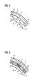
- the spacer elements 10 are disposed in between circumferentially adjacently disposed magnetic elements 6, i.e. in between respective gaps or slots extending in between two respective circumferentially adjacently disposed magnetic elements 6 (cf. fig. 4, 5 ). Thereby, the dimensions of a respective spacer element 10 are typically adapted to both the circumferential and axial dimensions of a respective gap extending between two respective circumferentially adjacently disposed magnetic elements 6.
- the spacer element 10 may be attached to the rotor 3 by any suitable and stable connection holding the spacer elements 10 safely in place, i.e. particularly by gluing, welding, brazing, or screwing connections.
- the spacer element 10 has the shape of a double-wedge.
- a respective spacer element 10 is generally a symmetrical component having a plane base area 11 and two ramp-like, inclination areas 12, 13 which are inclined relative to the base area 11.
- the respective inclination areas 12, 13 are inclined with an acute angle relative to the base area 11 (cf. inclination angles ⁇ ).
- the inclination angles ⁇ may be 1.4°, for instance.
- the inclination areas 12, 13 are oppositely inclined relative to the base area 10 so as to form a tip portion 14 at the axial centre of the spacer element 10 giving the spacer element 10 the mentioned double-wedge or roof-like shape.
- the specific shape of the spacer element 10 leads to a gradual change, i.e. decrease of the cross-section area of the air-gap 7 from the face sides of the generator towards its axial centre.
- the cross-section of the air-gap in the axial centre region of the generator may be reduced by ca. 25%, for instance (cf. the cross-sectional areas A1, A2 of the air-gap 7 shown in fig. 4, 5 ).
- Variations of the cross-section of the air-gap 7 may be mainly influenced by varying the inclination angles ⁇ of the inclination areas 12, 13.
- the axial flow velocity of the cooling gas may be concertedly influenced in such a manner that the cooling gas flows slower in the axially outer portions than in the axial centre.
- the radial flow velocity of the cooling gas is more evenly distributed along the axially disposed radial channels 9 so that the cooling efficiency of the cooling means may be improved.
- Known constructively cumbersome approaches for improving the cooling efficiency of the generator such as varying the axial dimensions of the radial channels 9 and/or increasing the number of the radial channels 9 are not necessarily required, yet in principle additionally possible. In such a manner, the problem of a pressure drop of the cooling gas within the radial channels 9 is not given with the inventive principle.
- a respective spacer element 10 may be a segmented component.
- Fig. 3 shows a principle side view of a spacer element 10 according to a second exemplary embodiment.
- the spacer element 10 comprises two separate spacer element segments 15, 16 adapted to build the spacer element 10 when assembled.
- the embodiment of fig. 3 shows two respective symmetrical spacer element segments 15, 16 both having a wedge-like shape so as to build the aforementioned double-wedge-like shape of the spacer element 10 when assembled or abuttingly disposed, i.e. with their respective opposing face sides abutting each other.
- a respective spacer element 10 may also be divided in more than two respective spacer element segments 15, 16.
- the respective spacer element segments are shaped in such a manner that, when assembled, the desired double-wedge-shape of the spacer element 10 may be obtained.
Landscapes
- Engineering & Computer Science (AREA)
- Power Engineering (AREA)
- Iron Core Of Rotating Electric Machines (AREA)
- Motor Or Generator Cooling System (AREA)
Abstract
Description
- The invention relates to a rotor arrangement for a generator, the rotor arrangement comprising a rotor having a number of circumferentially adjacently disposed magnetic elements.
- The operation of electric machines such as generators is accompanied by the generation of heat particularly originating from so called copper losses in the stator. In order to provide proper cooling of a respective electric machine, it is known to blow a gaseous cooling medium from the face sides of the electric machine into the air gap between the stator and the rotor of a respective electric machine. The gaseous cooling medium circulates in axial direction, i.e. axially along the air gap, and in radial direction, i.e. through respective radial channels or ducts within the stator, through the electric machine.
- Thereby, the axial flow velocity of the gaseous cooling medium is inversely proportional to the radial flow velocity of the gaseous cooling medium. Hence, due to the fact that the axial flow velocity of the gaseous cooling medium usually gradually decreases from the face sides to the centre of the generator or stator respectively, the radial flow velocity in the radial channels or ducts disposed in the regions of its face sides is usually lower in comparison to the radial flow velocity in the radial channels or ducts disposed in the centre portions of the generator or stator, respectively.
- This effect gives rise to an uneven axial distribution of the radial flow velocity of the gaseous cooling medium within respective radial channels or ducts and hence, negatively affects the cooling efficiency of the generator as a whole.
- It is the object of the invention to provide an improvement in the cooling efficiency of a respective generator.
- This is inventively achieved by a rotor arrangement as initially specified, which is characterised in that at least one axially extending spacer element is disposed between at least two circumferentially adjacently disposed magnetic elements.
- The present invention is based on the idea to concertedly influence the axial flow velocity of a respective gaseous cooling medium or cooling gas flowing in the air gap between the rotor and a respective stator along the axial length of the rotor or a generator which is equipped with an inventive rotor arrangement by means of respective axially extending, particularly longitudinally, spacer elements which are disposed in between at least two circumferentially adjacently disposed magnetic elements, i.e. permanent magnets or the like, of the rotor.
- Hence, the axial flow profile, i.e. particularly the axial flow velocity profile, of the cooling gas may be concertedly influenced or controlled aiming at an increase of the axial flow velocity in the axial centre region of the rotor or a stator being radially oppositely disposed relative to the rotor. In such a manner, i.e. by concertedly shaping the cross-section of the air-gap between the rotor and a stator, an even distribution of the axial flow velocity of the cooling gas may be accomplished which also leads to an even distribution of the radial flow velocity within respective radial channels or ducts of a respective stator since - as mentioned above - there is a correlation between the axial and the radial flow velocity of a respective cooling gas. All in all, the cooling efficiency of a respective generator which is equipped with an inventive rotor arrangement is improved since the cooling performance is more evenly distributed along its axial length.
- The aforementioned effect is not only based on the mere provision of respective spacer elements in between respective circumferentially adjacently disposed magnetic elements, but on their concrete geometrical shape which is chosen to concertedly influence, i.e. particularly adapt the aerodynamic flow profile of a respective cooling gas to be essentially constant in axial direction, i.e. along the air-gap extending between the rotor and a respective stator being radially oppositely disposed relative to the rotor.
- Regarding the number and arrangement of respective spacer elements arbitrary possibilities are given. Preferably, each circumferential gap between respective circumferentially adjacently disposed magnetic elements is provided with at least one respective spacer element. However it is also possible that certain circumferential gaps between respective circumferentially adjacently disposed magnetic elements may be left empty. Attachment of the spacer elements to the rotor, i.e. a rotor frame or the like may be established by gluing connections, welding connections, brazing connections, or screwing connections, for instance. It is also feasible to mechanically attach a spacer element to the rotor by means of corresponding form and/or force closure elements provided with the spacer element and the rotor. I.e., the connection between the spacer element and the rotor may be established by dovetail connection, i.e. respective protrusions and corresponding recesses provided with the spacer element and the rotor, or the like. Respective recesses and protrusions may be built by machining the rotor and/or the spacer element, for instance.
- Preferably, a spacer element has a plane base area attached to the rotor and at least one freely exposed inclination area which is inclined relative to the base area. Hence, the plane base area serves to provide a connection site for connecting the spacer element with the rotor, whereas the inclination area serves to actively influence the flow profile, i.e. particularly the axial flow velocity profile, of a respective cooling gas. Hence, the geometrical shape of the inclination area is chosen in such a manner so as to provide an even axial flow profile of the cooling gas. Hence, any concrete dimensions of a respective spacer elements as well as inclination angles have to be determined under consideration of a concrete constructive design of the rotor arrangement as well as a generator being equipped with the rotor arrangement.
- Generally, the when cutting a respective spacer element in axial direction it is of advantage that the inclination area comprises two symmetrically, oppositely inclined inclination area sections so that the respective shape of the spacer element may be deemed as a double-wedge- or roof-like shape. However, single-wedge- or (essentially) triangular- shapes of a respective spacer elements are also feasible. This especially applies, when the axial dimensions of a respective spacer element are below the axial dimensions of the rotor, so that generally at least two respective spacer elements may be axially subsequently disposed in between two circumferentially adjacently disposed magnetic elements.
- Hence, according to a preferred embodiment, a respective spacer element has a plane base area and two inclination areas which are inclined relative to the base area, whereby the inclination areas are oppositely inclined relative to the base area. In such a manner, an even axial and further radial flow profile of the cooling gas may be achieved. This embodiment is particularly advisable when blowing a cooling gas from both face sides of the generator in the air gap.
- In order to establish the aforementioned double-wedge- or roof-like shape of a respective spacer element, it is preferred that, when emanating from two respective inclination areas, the inclination areas are arranged in such a manner that they build a tip portion at the axial centre of the spacer element. Hence, the height of a respective spacer element increases from its face sides towards its centre so that a tip portion is built. Thereby, since the spacer element is preferably a symmetrical component, the slopes of the respective inclination areas are preferably equal.
- Yet, it is generally also possible that a spacer element is an asymmetrical component with respect to its axial centre. In such a manner, any differences between the flowing profiles of the cooling gas entering from the respective face sides of the generator or the rotor arrangement, respectively into the air-gap may be encountered. Hence, by considering the given flowing profile of the cooling gas entering the air-gap from both face sides of a specific generator construction for shaping the spacer element, a concerted control of the respective axial and radial flow velocities of the cooling gas in the air-gap may be attained.
- The double-wedge- or roof-like shape of a respective spacer element also embraces essentially double-wedge- or roof-like shapes, i.e. the inclination areas may be interrupted by respective flat areas. Respective flat areas may be particularly provided in the axial centre region of a respective spacer element in order to force even more cooling gas through the radial channels in the region of the face sides of the generator, i.e. in the region of the axial ends of the air-gap.
- Thereby, the respective inclination areas are inclined with an acute angle relative to the base area. Hence, the inclination angle is below 90° and usually lies in the range of 0.5 - 40°, particularly 1 - 10°, especially 1 - 2°. According to a concrete exemplary embodiment, a respective angle may be 1.4°.
- Instead of integrally building a respective spacer element, it is also possible that a respective spacer element is built of or comprises at least two separate spacer element segments adapted to build the spacer element when assembled.
- According to a simple embodiment, the spacer element segments may each represent a half of the complete spacer element, i.e. the spacer element is divided in two respective halves. When emanating from a spacer element having a double-wedge-like shape, each spacer element segment has the shape of a single wedge. To build the spacer element the vertically extending side planes of the respective spacer element segments are to be abutted so as to build the aforementioned double-wedge-like shape of the spacer element. Hence, a spacer element may be built of two, particularly cross-sectionally, symmetrical spacer element segments, with the spacer element segments having a cross-sectionally wedge-like shape.
- Of course, a respective spacer element may also comprise more than two respective spacer element segments. Thereby, the shapes, i.e. particularly slopes of the respective inclination areas, of the respective spacer element segments are preferably adapted to each other so an appropriate effect on the flow profile of cooling gas may be achieved.
- The present invention also relates to a generator, particularly for a wind turbine. The generator comprises a stator arrangement including stator and a rotor arrangement as specified above. All annotations regarding the inventive rotor arrangement also apply for the inventive generator.
- The invention is described in detail as reference is made to the figures, whereby:
-
Fig. 1 shows a principle axially cut view of a generator; -
Fig. 2 shows a principle side view of a spacer element according to a first exemplary embodiment; -
Fig. 3 shows principle side view of a spacer element according to a second exemplary embodiment; -
Fig. 4 shows a cut along line IV-IV infig. 1 ; and -
Fig. 5 shows a cut along line V-V infig. 1 . -
Fig. 1 shows a principle axially cut view of a generator 1 such as particularly used as a power generating unit in a wind turbine. The generator 1 comprises a ring-shaped stator 2 and a ring-shaped rotor 3 as part of a rotor arrangement 4, with therotor 3 being rotatably supported relative tostator 2 by means of appropriate bearing means so that therotor 3 may rotate around the central axis A. - The
stator 2 is provided with a number ofstator windings 5, whereby only the end portions of thestator windings 5 axially extending off thestator 2 are shown. Therotor 3 is provided with a number of axially extending, bar-likemagnetic elements 6 made of a permanent magnetic material. - The generator 1 is provided with a cooling means allowing air-cooling of the generator 1, i.e. the generator 1 is cooled by blowing a cooling gas, i.e. air for instance, from both face sides into the air-
gap 7 extending between therotor 3 and thestator 2. Therefore, the generator 1 comprises a number of fans or the like. The cooling gas extends in both axial and radial direction (cf. arrows 8), i.e. the cooling gas not only axially circulates through the air-gap 7 but also radially circulates through respectiveradial channels 9 are provided at defined axial positions along the axial length of thestator 2. - In order to actively influence the axial flow velocity of the cooling gas and hence, also the radial flow velocity of the cooling gas (since the axial flow velocity is inversely proportional to the radial flow velocity of the cooling gas),
respective spacer elements 10 are provided with therotor 3. - The
spacer elements 10 are disposed in between circumferentially adjacently disposedmagnetic elements 6, i.e. in between respective gaps or slots extending in between two respective circumferentially adjacently disposed magnetic elements 6 (cf.fig. 4, 5 ). Thereby, the dimensions of arespective spacer element 10 are typically adapted to both the circumferential and axial dimensions of a respective gap extending between two respective circumferentially adjacently disposedmagnetic elements 6. Thespacer element 10 may be attached to therotor 3 by any suitable and stable connection holding thespacer elements 10 safely in place, i.e. particularly by gluing, welding, brazing, or screwing connections. - As is particularly discernible from
fig. 2 showing a principle side view of aspacer element 10 according to a first exemplary embodiment, thespacer element 10 has the shape of a double-wedge. Hence, arespective spacer element 10 is generally a symmetrical component having aplane base area 11 and two ramp-like,inclination areas base area 11. Thereby, therespective inclination areas inclination areas base area 10 so as to form atip portion 14 at the axial centre of thespacer element 10 giving thespacer element 10 the mentioned double-wedge or roof-like shape. - The specific shape of the
spacer element 10 leads to a gradual change, i.e. decrease of the cross-section area of the air-gap 7 from the face sides of the generator towards its axial centre. In such a manner, the cross-section of the air-gap in the axial centre region of the generator may be reduced by ca. 25%, for instance (cf. the cross-sectional areas A1, A2 of the air-gap 7 shown infig. 4, 5 ). Variations of the cross-section of the air-gap 7 may be mainly influenced by varying the inclination angles α of theinclination areas - Accordingly, the axial flow velocity of the cooling gas may be concertedly influenced in such a manner that the cooling gas flows slower in the axially outer portions than in the axial centre. Hence, it may be achieved that the radial flow velocity of the cooling gas is more evenly distributed along the axially disposed
radial channels 9 so that the cooling efficiency of the cooling means may be improved. Known constructively cumbersome approaches for improving the cooling efficiency of the generator such as varying the axial dimensions of theradial channels 9 and/or increasing the number of theradial channels 9 are not necessarily required, yet in principle additionally possible. In such a manner, the problem of a pressure drop of the cooling gas within theradial channels 9 is not given with the inventive principle. - Instead of a
respective spacer element 10 being an integral component, it is also possible that arespective spacer element 10 may be a segmented component.Fig. 3 shows a principle side view of aspacer element 10 according to a second exemplary embodiment. Thereby, thespacer element 10 comprises two separatespacer element segments spacer element 10 when assembled. The embodiment offig. 3 shows two respective symmetricalspacer element segments spacer element 10 when assembled or abuttingly disposed, i.e. with their respective opposing face sides abutting each other. Likewise, arespective spacer element 10 may also be divided in more than two respectivespacer element segments spacer element 10 may be obtained. - Although the present invention has been described in detail with reference to the preferred embodiment, the present invention is not limited by the disclosed examples from which the skilled person is able to derive other variations without departing from the scope of the invention.
Claims (9)
- Rotor arrangement (4) for a generator (1), the rotor arrangement (4) comprising a rotor (3) having a number of circumferentially adjacently disposed magnetic elements (6), characterised in that at least one axially extending spacer element (10) is disposed between at least two circumferentially adjacently disposed magnetic elements (6).
- Rotor arrangement according to claim 1, wherein a spacer element (10) has a plane base area (11) attached to the rotor (3) and at least one freely exposed inclination area (12, 13) which is inclined relative to the base area (11).
- Rotor arrangement according to claim 1 or 2, wherein a spacer element (10) has a plane base area (11) and two inclination areas (12, 13) which are inclined relative to the base area (11), whereby the inclination areas (12, 13) are oppositely inclined relative to the base area (11).
- Rotor arrangement according to claim 3, wherein the inclination areas (12, 13) are arranged in such a manner that they build a tip portion (14) at the axial centre of the spacer element (10).
- Rotor arrangement according to claim 3 or 4, wherein the inclination areas (12, 13) are inclined with an acute angle (α) relative to the base area (11).
- Rotor arrangement according to one of the preceding claims, wherein a respective spacer element (10) is built of at least two separate spacer element segments (15, 16) adapted to build the spacer element (10) when assembled.
- Rotor arrangement according to claim 6, wherein a spacer element (10) is built of two, particularly cross-sectionally, symmetrical spacer element segments (15, 16), with the spacer element segments (15, 16) having a cross-sectionally wedge-like shape.
- Rotor arrangement according to one of the preceding claims, wherein at least one spacer element (10) is disposed between all circumferentially adjacently disposed magnetic elements (6).
- Generator (1), particularly for a wind turbine, comprising a stator (2) and a rotor arrangement (4) according to one of the preceding claims.
Priority Applications (4)
| Application Number | Priority Date | Filing Date | Title |
|---|---|---|---|
| DK12162964.6T DK2648316T3 (en) | 2012-04-03 | 2012-04-03 | A rotor assembly |
| EP12162964.6A EP2648316B1 (en) | 2012-04-03 | 2012-04-03 | Rotor arrangement |
| US13/852,470 US9203283B2 (en) | 2012-04-03 | 2013-03-28 | Rotor arrangement for a generator |
| CN201310219052.3A CN103368291B (en) | 2012-04-03 | 2013-04-03 | Rotor arrangement |
Applications Claiming Priority (1)
| Application Number | Priority Date | Filing Date | Title |
|---|---|---|---|
| EP12162964.6A EP2648316B1 (en) | 2012-04-03 | 2012-04-03 | Rotor arrangement |
Publications (2)
| Publication Number | Publication Date |
|---|---|
| EP2648316A1 true EP2648316A1 (en) | 2013-10-09 |
| EP2648316B1 EP2648316B1 (en) | 2020-05-27 |
Family
ID=45929418
Family Applications (1)
| Application Number | Title | Priority Date | Filing Date |
|---|---|---|---|
| EP12162964.6A Not-in-force EP2648316B1 (en) | 2012-04-03 | 2012-04-03 | Rotor arrangement |
Country Status (4)
| Country | Link |
|---|---|
| US (1) | US9203283B2 (en) |
| EP (1) | EP2648316B1 (en) |
| CN (1) | CN103368291B (en) |
| DK (1) | DK2648316T3 (en) |
Cited By (3)
| Publication number | Priority date | Publication date | Assignee | Title |
|---|---|---|---|---|
| US10103590B2 (en) | 2014-05-19 | 2018-10-16 | Ge Renewable Technologies Wind B.V. | Permanent magnet rotor assembly for a wind turbine using a wedge attachment mechanism |
| EP3460961A1 (en) * | 2017-09-25 | 2019-03-27 | Siemens Gamesa Renewable Energy A/S | Stator for an electrical generator in a wind turbine |
| EP3537576A1 (en) * | 2018-03-06 | 2019-09-11 | Siemens Gamesa Renewable Energy A/S | Generator for a wind turbine |
Families Citing this family (8)
| Publication number | Priority date | Publication date | Assignee | Title |
|---|---|---|---|---|
| US10554091B2 (en) * | 2014-08-22 | 2020-02-04 | Regal Beloit America, Inc. | Electric machine with rotor, stator and housing cooling passages |
| EP3182562A1 (en) * | 2015-12-14 | 2017-06-21 | General Electric Technology GmbH | A slip ring arrangement for an electric machine |
| US9822998B2 (en) * | 2016-03-17 | 2017-11-21 | Daikin Applied Americas Inc. | Centrifugal compressor with motor cooling |
| EP3588751B1 (en) * | 2018-06-28 | 2021-01-27 | Siemens Gamesa Renewable Energy A/S | Generator of a wind turbine having an air flow adaptor |
| CN109149828B (en) | 2018-08-30 | 2020-04-07 | 新疆金风科技股份有限公司 | Slot wedge element, stator device, motor and wind generating set |
| JP7077903B2 (en) * | 2018-10-04 | 2022-05-31 | トヨタ自動車株式会社 | Rotating electric machine |
| CN110460180B (en) * | 2019-08-30 | 2020-11-03 | 东方电气集团东方电机有限公司 | Method for improving axial temperature distribution uniformity of stator |
| US11827110B1 (en) | 2021-05-24 | 2023-11-28 | Mark Ogram | Protective system for a rechargeable battery |
Citations (3)
| Publication number | Priority date | Publication date | Assignee | Title |
|---|---|---|---|---|
| US4219752A (en) * | 1977-06-24 | 1980-08-26 | Nippondenso Co., Ltd. | Rotor for a magneto generator |
| DE102004031329A1 (en) * | 2004-06-29 | 2006-01-19 | Klinger, Friedrich, Prof. Dr. Ing. | External rotor for a generator in a wind power installation has an outer ring (OR) and a grouping with a permanent magnet of components following each other at a tangent on the OR inner side |
| EP1914864A2 (en) * | 2006-10-21 | 2008-04-23 | ESW GmbH | Assembly for mounting permanent magnets on rapid rotary rotors of electric machines |
Family Cites Families (4)
| Publication number | Priority date | Publication date | Assignee | Title |
|---|---|---|---|---|
| US4260921A (en) * | 1978-12-26 | 1981-04-07 | The Garrett Corporation | Permanent magnet rotor assembly having rectangularly shaped tongues |
| CN2560151Y (en) * | 2002-01-10 | 2003-07-09 | 武汉三维汽轮电机股份有限公司 | Large indoor cooled steam turbogenerator cooling structure |
| US7215038B2 (en) * | 2005-07-26 | 2007-05-08 | Bacon C Richard | Wind wheel and electricity generator using same |
| CN101626185A (en) * | 2009-08-05 | 2010-01-13 | 南通金驰机电有限公司 | Permanent magnet synchronous motor |
-
2012
- 2012-04-03 DK DK12162964.6T patent/DK2648316T3/en active
- 2012-04-03 EP EP12162964.6A patent/EP2648316B1/en not_active Not-in-force
-
2013
- 2013-03-28 US US13/852,470 patent/US9203283B2/en active Active
- 2013-04-03 CN CN201310219052.3A patent/CN103368291B/en not_active Expired - Fee Related
Patent Citations (3)
| Publication number | Priority date | Publication date | Assignee | Title |
|---|---|---|---|---|
| US4219752A (en) * | 1977-06-24 | 1980-08-26 | Nippondenso Co., Ltd. | Rotor for a magneto generator |
| DE102004031329A1 (en) * | 2004-06-29 | 2006-01-19 | Klinger, Friedrich, Prof. Dr. Ing. | External rotor for a generator in a wind power installation has an outer ring (OR) and a grouping with a permanent magnet of components following each other at a tangent on the OR inner side |
| EP1914864A2 (en) * | 2006-10-21 | 2008-04-23 | ESW GmbH | Assembly for mounting permanent magnets on rapid rotary rotors of electric machines |
Cited By (4)
| Publication number | Priority date | Publication date | Assignee | Title |
|---|---|---|---|---|
| US10103590B2 (en) | 2014-05-19 | 2018-10-16 | Ge Renewable Technologies Wind B.V. | Permanent magnet rotor assembly for a wind turbine using a wedge attachment mechanism |
| EP3460961A1 (en) * | 2017-09-25 | 2019-03-27 | Siemens Gamesa Renewable Energy A/S | Stator for an electrical generator in a wind turbine |
| EP3537576A1 (en) * | 2018-03-06 | 2019-09-11 | Siemens Gamesa Renewable Energy A/S | Generator for a wind turbine |
| US11028834B2 (en) | 2018-03-06 | 2021-06-08 | Siemens Gamesa Renewable Energy A/S | Generator for a wind turbine |
Also Published As
| Publication number | Publication date |
|---|---|
| DK2648316T3 (en) | 2020-08-03 |
| CN103368291A (en) | 2013-10-23 |
| EP2648316B1 (en) | 2020-05-27 |
| US9203283B2 (en) | 2015-12-01 |
| US20130257195A1 (en) | 2013-10-03 |
| CN103368291B (en) | 2017-09-15 |
Similar Documents
| Publication | Publication Date | Title |
|---|---|---|
| EP2648316B1 (en) | Rotor arrangement | |
| ES2889975T3 (en) | Generator preferably from a wind turbine | |
| US7825552B2 (en) | Cooling arrangement for a variable reluctance electric machine | |
| EP2670026A1 (en) | Spacer-less air duct | |
| EP2779366B1 (en) | Electrical machine having cooling features | |
| EP2403107A1 (en) | Permanent magnet type rotary machine | |
| US20110163640A1 (en) | Rotor cooling for a dynamoelectric machine | |
| JP2018528755A (en) | Rotating electric machine having a rotor and a stator for passing fluid | |
| KR102892890B1 (en) | Generators and wind turbines for power generation | |
| EP3109974B1 (en) | Systems for improved heat transfer from rotor coils | |
| CN106849433B (en) | Adopt horizontal air gap of vice groove air feed cooled turbogenerator rotor | |
| CA2752979C (en) | Generator for an electrical machine | |
| US8729750B2 (en) | Stator arrangement | |
| CN102570670A (en) | Rotor with internal spacers and motor employing rotor | |
| US10128717B2 (en) | Ring for an electric machine | |
| EP2761173B1 (en) | Air cooling of wind turbine generator | |
| KR20170085062A (en) | Turbine blade | |
| JP7313729B2 (en) | generator rotor and wind generator | |
| EP2899850B1 (en) | Electric generator for a wind turbine with stator gaps varying in axial direction of the generator | |
| CN107078605A (en) | Electrokinetic machinery with cooling flow channels | |
| CN106230155B (en) | More matched motor ventilation structures of structural channels | |
| KR101078312B1 (en) | Power generating device using fluid flowing through pipe and power generating device using same | |
| CN106253526A (en) | Combine the electric machine structure of dissimilar channel-section steel | |
| CN106300708B (en) | A motor rotor ventilation structure with three channel steels installed | |
| CN105141055A (en) | Rotor |
Legal Events
| Date | Code | Title | Description |
|---|---|---|---|
| PUAI | Public reference made under article 153(3) epc to a published international application that has entered the european phase |
Free format text: ORIGINAL CODE: 0009012 |
|
| AK | Designated contracting states |
Kind code of ref document: A1 Designated state(s): AL AT BE BG CH CY CZ DE DK EE ES FI FR GB GR HR HU IE IS IT LI LT LU LV MC MK MT NL NO PL PT RO RS SE SI SK SM TR |
|
| AX | Request for extension of the european patent |
Extension state: BA ME |
|
| 17P | Request for examination filed |
Effective date: 20131106 |
|
| RBV | Designated contracting states (corrected) |
Designated state(s): AL AT BE BG CH CY CZ DE DK EE ES FI FR GB GR HR HU IE IS IT LI LT LU LV MC MK MT NL NO PL PT RO RS SE SI SK SM TR |
|
| 17Q | First examination report despatched |
Effective date: 20140129 |
|
| RAP1 | Party data changed (applicant data changed or rights of an application transferred) |
Owner name: SIEMENS AKTIENGESELLSCHAFT |
|
| RAP1 | Party data changed (applicant data changed or rights of an application transferred) |
Owner name: SIEMENS GAMESA RENEWABLE ENERGY A/S |
|
| GRAP | Despatch of communication of intention to grant a patent |
Free format text: ORIGINAL CODE: EPIDOSNIGR1 |
|
| STAA | Information on the status of an ep patent application or granted ep patent |
Free format text: STATUS: GRANT OF PATENT IS INTENDED |
|
| RIC1 | Information provided on ipc code assigned before grant |
Ipc: H02K 1/27 20060101AFI20191204BHEP Ipc: H02K 1/32 20060101ALI20191204BHEP Ipc: H02K 1/20 20060101ALN20191204BHEP |
|
| RIC1 | Information provided on ipc code assigned before grant |
Ipc: H02K 1/27 20060101AFI20191211BHEP Ipc: H02K 1/20 20060101ALN20191211BHEP Ipc: H02K 1/32 20060101ALI20191211BHEP |
|
| INTG | Intention to grant announced |
Effective date: 20200102 |
|
| GRAS | Grant fee paid |
Free format text: ORIGINAL CODE: EPIDOSNIGR3 |
|
| GRAA | (expected) grant |
Free format text: ORIGINAL CODE: 0009210 |
|
| STAA | Information on the status of an ep patent application or granted ep patent |
Free format text: STATUS: THE PATENT HAS BEEN GRANTED |
|
| AK | Designated contracting states |
Kind code of ref document: B1 Designated state(s): AL AT BE BG CH CY CZ DE DK EE ES FI FR GB GR HR HU IE IS IT LI LT LU LV MC MK MT NL NO PL PT RO RS SE SI SK SM TR |
|
| REG | Reference to a national code |
Ref country code: GB Ref legal event code: FG4D |
|
| REG | Reference to a national code |
Ref country code: CH Ref legal event code: EP |
|
| REG | Reference to a national code |
Ref country code: DE Ref legal event code: R096 Ref document number: 602012070297 Country of ref document: DE |
|
| REG | Reference to a national code |
Ref country code: AT Ref legal event code: REF Ref document number: 1275581 Country of ref document: AT Kind code of ref document: T Effective date: 20200615 |
|
| REG | Reference to a national code |
Ref country code: DK Ref legal event code: T3 Effective date: 20200731 |
|
| REG | Reference to a national code |
Ref country code: NL Ref legal event code: FP |
|
| REG | Reference to a national code |
Ref country code: LT Ref legal event code: MG4D |
|
| PG25 | Lapsed in a contracting state [announced via postgrant information from national office to epo] |
Ref country code: SE Free format text: LAPSE BECAUSE OF FAILURE TO SUBMIT A TRANSLATION OF THE DESCRIPTION OR TO PAY THE FEE WITHIN THE PRESCRIBED TIME-LIMIT Effective date: 20200527 Ref country code: PT Free format text: LAPSE BECAUSE OF FAILURE TO SUBMIT A TRANSLATION OF THE DESCRIPTION OR TO PAY THE FEE WITHIN THE PRESCRIBED TIME-LIMIT Effective date: 20200928 Ref country code: FI Free format text: LAPSE BECAUSE OF FAILURE TO SUBMIT A TRANSLATION OF THE DESCRIPTION OR TO PAY THE FEE WITHIN THE PRESCRIBED TIME-LIMIT Effective date: 20200527 Ref country code: GR Free format text: LAPSE BECAUSE OF FAILURE TO SUBMIT A TRANSLATION OF THE DESCRIPTION OR TO PAY THE FEE WITHIN THE PRESCRIBED TIME-LIMIT Effective date: 20200828 Ref country code: NO Free format text: LAPSE BECAUSE OF FAILURE TO SUBMIT A TRANSLATION OF THE DESCRIPTION OR TO PAY THE FEE WITHIN THE PRESCRIBED TIME-LIMIT Effective date: 20200827 Ref country code: IS Free format text: LAPSE BECAUSE OF FAILURE TO SUBMIT A TRANSLATION OF THE DESCRIPTION OR TO PAY THE FEE WITHIN THE PRESCRIBED TIME-LIMIT Effective date: 20200927 Ref country code: LT Free format text: LAPSE BECAUSE OF FAILURE TO SUBMIT A TRANSLATION OF THE DESCRIPTION OR TO PAY THE FEE WITHIN THE PRESCRIBED TIME-LIMIT Effective date: 20200527 |
|
| PG25 | Lapsed in a contracting state [announced via postgrant information from national office to epo] |
Ref country code: LV Free format text: LAPSE BECAUSE OF FAILURE TO SUBMIT A TRANSLATION OF THE DESCRIPTION OR TO PAY THE FEE WITHIN THE PRESCRIBED TIME-LIMIT Effective date: 20200527 Ref country code: RS Free format text: LAPSE BECAUSE OF FAILURE TO SUBMIT A TRANSLATION OF THE DESCRIPTION OR TO PAY THE FEE WITHIN THE PRESCRIBED TIME-LIMIT Effective date: 20200527 Ref country code: BG Free format text: LAPSE BECAUSE OF FAILURE TO SUBMIT A TRANSLATION OF THE DESCRIPTION OR TO PAY THE FEE WITHIN THE PRESCRIBED TIME-LIMIT Effective date: 20200827 Ref country code: HR Free format text: LAPSE BECAUSE OF FAILURE TO SUBMIT A TRANSLATION OF THE DESCRIPTION OR TO PAY THE FEE WITHIN THE PRESCRIBED TIME-LIMIT Effective date: 20200527 |
|
| REG | Reference to a national code |
Ref country code: AT Ref legal event code: MK05 Ref document number: 1275581 Country of ref document: AT Kind code of ref document: T Effective date: 20200527 |
|
| PG25 | Lapsed in a contracting state [announced via postgrant information from national office to epo] |
Ref country code: AL Free format text: LAPSE BECAUSE OF FAILURE TO SUBMIT A TRANSLATION OF THE DESCRIPTION OR TO PAY THE FEE WITHIN THE PRESCRIBED TIME-LIMIT Effective date: 20200527 |
|
| PG25 | Lapsed in a contracting state [announced via postgrant information from national office to epo] |
Ref country code: RO Free format text: LAPSE BECAUSE OF FAILURE TO SUBMIT A TRANSLATION OF THE DESCRIPTION OR TO PAY THE FEE WITHIN THE PRESCRIBED TIME-LIMIT Effective date: 20200527 Ref country code: CZ Free format text: LAPSE BECAUSE OF FAILURE TO SUBMIT A TRANSLATION OF THE DESCRIPTION OR TO PAY THE FEE WITHIN THE PRESCRIBED TIME-LIMIT Effective date: 20200527 Ref country code: EE Free format text: LAPSE BECAUSE OF FAILURE TO SUBMIT A TRANSLATION OF THE DESCRIPTION OR TO PAY THE FEE WITHIN THE PRESCRIBED TIME-LIMIT Effective date: 20200527 Ref country code: AT Free format text: LAPSE BECAUSE OF FAILURE TO SUBMIT A TRANSLATION OF THE DESCRIPTION OR TO PAY THE FEE WITHIN THE PRESCRIBED TIME-LIMIT Effective date: 20200527 Ref country code: IT Free format text: LAPSE BECAUSE OF FAILURE TO SUBMIT A TRANSLATION OF THE DESCRIPTION OR TO PAY THE FEE WITHIN THE PRESCRIBED TIME-LIMIT Effective date: 20200527 Ref country code: SM Free format text: LAPSE BECAUSE OF FAILURE TO SUBMIT A TRANSLATION OF THE DESCRIPTION OR TO PAY THE FEE WITHIN THE PRESCRIBED TIME-LIMIT Effective date: 20200527 Ref country code: ES Free format text: LAPSE BECAUSE OF FAILURE TO SUBMIT A TRANSLATION OF THE DESCRIPTION OR TO PAY THE FEE WITHIN THE PRESCRIBED TIME-LIMIT Effective date: 20200527 |
|
| PG25 | Lapsed in a contracting state [announced via postgrant information from national office to epo] |
Ref country code: SK Free format text: LAPSE BECAUSE OF FAILURE TO SUBMIT A TRANSLATION OF THE DESCRIPTION OR TO PAY THE FEE WITHIN THE PRESCRIBED TIME-LIMIT Effective date: 20200527 Ref country code: PL Free format text: LAPSE BECAUSE OF FAILURE TO SUBMIT A TRANSLATION OF THE DESCRIPTION OR TO PAY THE FEE WITHIN THE PRESCRIBED TIME-LIMIT Effective date: 20200527 |
|
| REG | Reference to a national code |
Ref country code: DE Ref legal event code: R097 Ref document number: 602012070297 Country of ref document: DE |
|
| PLBE | No opposition filed within time limit |
Free format text: ORIGINAL CODE: 0009261 |
|
| STAA | Information on the status of an ep patent application or granted ep patent |
Free format text: STATUS: NO OPPOSITION FILED WITHIN TIME LIMIT |
|
| 26N | No opposition filed |
Effective date: 20210302 |
|
| PG25 | Lapsed in a contracting state [announced via postgrant information from national office to epo] |
Ref country code: SI Free format text: LAPSE BECAUSE OF FAILURE TO SUBMIT A TRANSLATION OF THE DESCRIPTION OR TO PAY THE FEE WITHIN THE PRESCRIBED TIME-LIMIT Effective date: 20200527 |
|
| PG25 | Lapsed in a contracting state [announced via postgrant information from national office to epo] |
Ref country code: MC Free format text: LAPSE BECAUSE OF FAILURE TO SUBMIT A TRANSLATION OF THE DESCRIPTION OR TO PAY THE FEE WITHIN THE PRESCRIBED TIME-LIMIT Effective date: 20200527 |
|
| PG25 | Lapsed in a contracting state [announced via postgrant information from national office to epo] |
Ref country code: LU Free format text: LAPSE BECAUSE OF NON-PAYMENT OF DUE FEES Effective date: 20210403 |
|
| REG | Reference to a national code |
Ref country code: BE Ref legal event code: MM Effective date: 20210430 |
|
| PG25 | Lapsed in a contracting state [announced via postgrant information from national office to epo] |
Ref country code: LI Free format text: LAPSE BECAUSE OF NON-PAYMENT OF DUE FEES Effective date: 20210430 Ref country code: CH Free format text: LAPSE BECAUSE OF NON-PAYMENT OF DUE FEES Effective date: 20210430 |
|
| REG | Reference to a national code |
Ref country code: FR Ref legal event code: PLFP Year of fee payment: 11 |
|
| PG25 | Lapsed in a contracting state [announced via postgrant information from national office to epo] |
Ref country code: IE Free format text: LAPSE BECAUSE OF NON-PAYMENT OF DUE FEES Effective date: 20210403 |
|
| PG25 | Lapsed in a contracting state [announced via postgrant information from national office to epo] |
Ref country code: BE Free format text: LAPSE BECAUSE OF NON-PAYMENT OF DUE FEES Effective date: 20210430 |
|
| REG | Reference to a national code |
Ref country code: DE Ref legal event code: R082 Ref document number: 602012070297 Country of ref document: DE Representative=s name: SAUTHOFF, KARSTEN, DIPL.-ING. UNIV., DE |
|
| PG25 | Lapsed in a contracting state [announced via postgrant information from national office to epo] |
Ref country code: HU Free format text: LAPSE BECAUSE OF FAILURE TO SUBMIT A TRANSLATION OF THE DESCRIPTION OR TO PAY THE FEE WITHIN THE PRESCRIBED TIME-LIMIT; INVALID AB INITIO Effective date: 20120403 Ref country code: CY Free format text: LAPSE BECAUSE OF FAILURE TO SUBMIT A TRANSLATION OF THE DESCRIPTION OR TO PAY THE FEE WITHIN THE PRESCRIBED TIME-LIMIT Effective date: 20200527 |
|
| PGFP | Annual fee paid to national office [announced via postgrant information from national office to epo] |
Ref country code: NL Payment date: 20230417 Year of fee payment: 12 |
|
| PGFP | Annual fee paid to national office [announced via postgrant information from national office to epo] |
Ref country code: FR Payment date: 20230417 Year of fee payment: 12 Ref country code: DK Payment date: 20230419 Year of fee payment: 12 Ref country code: DE Payment date: 20230418 Year of fee payment: 12 |
|
| PGFP | Annual fee paid to national office [announced via postgrant information from national office to epo] |
Ref country code: GB Payment date: 20230420 Year of fee payment: 12 |
|
| PG25 | Lapsed in a contracting state [announced via postgrant information from national office to epo] |
Ref country code: MK Free format text: LAPSE BECAUSE OF FAILURE TO SUBMIT A TRANSLATION OF THE DESCRIPTION OR TO PAY THE FEE WITHIN THE PRESCRIBED TIME-LIMIT Effective date: 20200527 |
|
| PG25 | Lapsed in a contracting state [announced via postgrant information from national office to epo] |
Ref country code: MT Free format text: LAPSE BECAUSE OF FAILURE TO SUBMIT A TRANSLATION OF THE DESCRIPTION OR TO PAY THE FEE WITHIN THE PRESCRIBED TIME-LIMIT Effective date: 20200527 |
|
| REG | Reference to a national code |
Ref country code: DE Ref legal event code: R119 Ref document number: 602012070297 Country of ref document: DE |
|
| REG | Reference to a national code |
Ref country code: DK Ref legal event code: EBP Effective date: 20240430 |
|
| REG | Reference to a national code |
Ref country code: NL Ref legal event code: MM Effective date: 20240501 |
|
| GBPC | Gb: european patent ceased through non-payment of renewal fee |
Effective date: 20240403 |
|
| PG25 | Lapsed in a contracting state [announced via postgrant information from national office to epo] |
Ref country code: DE Free format text: LAPSE BECAUSE OF NON-PAYMENT OF DUE FEES Effective date: 20241105 |
|
| PG25 | Lapsed in a contracting state [announced via postgrant information from national office to epo] |
Ref country code: NL Free format text: LAPSE BECAUSE OF NON-PAYMENT OF DUE FEES Effective date: 20240501 |
|
| PG25 | Lapsed in a contracting state [announced via postgrant information from national office to epo] |
Ref country code: GB Free format text: LAPSE BECAUSE OF NON-PAYMENT OF DUE FEES Effective date: 20240403 |
|
| PG25 | Lapsed in a contracting state [announced via postgrant information from national office to epo] |
Ref country code: FR Free format text: LAPSE BECAUSE OF NON-PAYMENT OF DUE FEES Effective date: 20240430 |
|
| PG25 | Lapsed in a contracting state [announced via postgrant information from national office to epo] |
Ref country code: NL Free format text: LAPSE BECAUSE OF NON-PAYMENT OF DUE FEES Effective date: 20240501 Ref country code: GB Free format text: LAPSE BECAUSE OF NON-PAYMENT OF DUE FEES Effective date: 20240403 Ref country code: FR Free format text: LAPSE BECAUSE OF NON-PAYMENT OF DUE FEES Effective date: 20240430 Ref country code: DE Free format text: LAPSE BECAUSE OF NON-PAYMENT OF DUE FEES Effective date: 20241105 |
|
| PG25 | Lapsed in a contracting state [announced via postgrant information from national office to epo] |
Ref country code: DK Free format text: LAPSE BECAUSE OF NON-PAYMENT OF DUE FEES Effective date: 20240430 |
|
| PG25 | Lapsed in a contracting state [announced via postgrant information from national office to epo] |
Ref country code: TR Free format text: LAPSE BECAUSE OF FAILURE TO SUBMIT A TRANSLATION OF THE DESCRIPTION OR TO PAY THE FEE WITHIN THE PRESCRIBED TIME-LIMIT Effective date: 20200527 |