EP2648301A1 - Method of electrical protection of a synchronous machine and electric power generation plant for powering an electric network - Google Patents
Method of electrical protection of a synchronous machine and electric power generation plant for powering an electric network Download PDFInfo
- Publication number
- EP2648301A1 EP2648301A1 EP12382130.8A EP12382130A EP2648301A1 EP 2648301 A1 EP2648301 A1 EP 2648301A1 EP 12382130 A EP12382130 A EP 12382130A EP 2648301 A1 EP2648301 A1 EP 2648301A1
- Authority
- EP
- European Patent Office
- Prior art keywords
- synchronous machine
- switch
- intensity
- protection
- measuring
- Prior art date
- Legal status (The legal status is an assumption and is not a legal conclusion. Google has not performed a legal analysis and makes no representation as to the accuracy of the status listed.)
- Granted
Links
Images


Classifications
-
- H—ELECTRICITY
- H02—GENERATION; CONVERSION OR DISTRIBUTION OF ELECTRIC POWER
- H02J—ELECTRIC POWER NETWORKS; CIRCUIT ARRANGEMENTS OR SYSTEMS FOR SUPPLYING OR DISTRIBUTING ELECTRIC POWER; SYSTEMS FOR STORING ELECTRIC ENERGY
- H02J3/00—Circuit arrangements for AC mains or AC distribution networks
- H02J3/38—Arrangements for feeding a single network from two or more generators or sources in parallel; Arrangements for feeding already energised networks from additional generators or sources in parallel
- H02J3/40—Synchronisation of generators for connection to a network or to another generator
- H02J3/42—Synchronisation of generators for connection to a network or to another generator with automatic parallel connection when synchronisation is achieved
-
- H—ELECTRICITY
- H02—GENERATION; CONVERSION OR DISTRIBUTION OF ELECTRIC POWER
- H02H—EMERGENCY PROTECTIVE CIRCUIT ARRANGEMENTS
- H02H7/00—Emergency protective circuit arrangements specially adapted for specific types of electric machines or apparatus or for sectionalised protection of cable or line systems, and effecting automatic switching in the event of an undesired change from normal working conditions
- H02H7/06—Emergency protective circuit arrangements specially adapted for specific types of electric machines or apparatus or for sectionalised protection of cable or line systems, and effecting automatic switching in the event of an undesired change from normal working conditions for dynamo-electric generators; for synchronous capacitors
-
- H—ELECTRICITY
- H02—GENERATION; CONVERSION OR DISTRIBUTION OF ELECTRIC POWER
- H02P—CONTROL OR REGULATION OF ELECTRIC MOTORS, ELECTRIC GENERATORS OR DYNAMO-ELECTRIC CONVERTERS; CONTROLLING TRANSFORMERS, REACTORS OR CHOKE COILS
- H02P9/00—Arrangements for controlling electric generators for the purpose of obtaining a desired output
- H02P9/04—Control effected upon non-electric prime mover and dependent upon electric output value of the generator
Definitions
- the present invention relates to a method of electrical protection of a synchronous machine, for example a generator, and an electric power generation plant for powering an electric network comprising an electrical protection for synchronising a synchronous machine to an electric network.
- the method of protection according to the invention establishes a period in which the electrical protection is active and also the instant in which said protection ceases to be active to offer the protection necessary and at the same time not prevent the correct increase of charge.
- Electric generators can be withdrawn from service for various reasons, such as the variation of charge, its own maintenance or emergency situations, among others. Each time putting a generator in service again is desired, it must be synchronised with the network before proceeding to close the switch. This synchronisation implies that the voltage in generator terminals has amplitude and frequency equal or similar to that of the network voltage in the connection point, as well as a practically null phase difference. The sequence of the three-phase voltage system of the generator must further be identical to that of the electric network.
- An incorrect synchronisation operation can involve serious damage to the generator, to the turbine or to the main transformer, caused by the electric and mechanical surges created, as well as introducing serious disruptions in the network.
- the severity of the damage caused by closing the switch in out of synchronism conditions depends on the short-circuit current in the connection point with the power network and mainly on the phase difference between the network voltage and on the machine to be coupled. The greater this short-circuit current and the phase difference are, the greater the current which will flow through each phase of the generator will be.
- coupling operations for coupling generators to the electric network can be performed manually or automatically by means of automatic synchronisers.
- the electric generator rotates with voltage in its terminals
- the possible operating errors, the existence of faulty devices or even that the synchroniser is out of service can close the group switch in out of synchronism conditions.
- the surges caused by the coupling operations without synchronism conditions cannot be instantly cleared by any other existing protection function and the consequences can be very severe.
- the 50/27 protection function is based on an instantaneous overcurrent protection which is active while the voltage in generator terminals is less than approximately 80%, such that in the event of detecting an overcurrent greater than a current threshold value (around 10% of the nominal intensity) while the voltage is less than the activation voltage threshold (the mentioned 80% for example), the protection function detects that the switch has been closed inadequately.
- a current threshold value around 10% of the nominal intensity
- the 50/27 function does not solve the problem.
- Overcurrent protectors are not incorporated in electric power generation plants since, in the event of a short-circuit in the network, the plant has to keep supplying power without decoupling so that the overcurrent protection systems distributed throughout the network isolate the sections where the short-circuit is produced, maintaining service in the rest of the network.
- the main technical problem which the invention solves is that of finding a specific protection function for the process of coupling synchronous machines to the electric network.
- the present invention solves the problem described above by means of a method of protection of a synchronous machine according to claim 1 and an electric power generation plant for powering an electric network according to claim 4.
- a first inventive aspect is a method of electrical protection of a synchronous machine in synchronisation when said synchronous machine is coupled with an electric network, at least the following elements intervening in the synchronisation:
- the method of electrical protection acts on a system of synchronisation of a synchronous machine to an electric network.
- a method of synchronisation is performed in a scenario comprising elements such as a turbo type machine, which can be any type of turbine, which is controlled for example with water or water vapour the pressure of which controls the rotation speed of the turbine.
- the turbine transfers torque to the synchronous machine through a shaft.
- the synchronous machine comprises a synchroniser and a voltage regulator.
- the synchroniser acts such that when the machine and network voltages have the same amplitude, the same frequency and a practically null phase difference, it sends the command to close the group switch.
- the group switch In the event of a fault of this synchroniser, or due to human error, the group switch can be closed in out of synchronism conditions. It is for this reason that a protection like that of the present invention is necessary.
- the invention assures that the overcurrent protection is only active for a limited time period during the synchronisation and acts in the manner detailed below using the following elements: an actuator suitable for opening the switch, a process control unit, which can be processing means, measuring means for measuring the intensity delivered from the synchronous machine to the electric network arranged at least in one of the phases with an intensity reading signal output connected to the process control unit; and in turn, the process control unit has an output connected to the actuator to command opening the switch.
- detection means for detecting the closing of the switch which in one embodiment can be an intensity detector at the output of the synchronous machine or any closed switch detection means.
- the critical moment is therefore the moment in which the closing of the automatic switch occurs.
- the invention maintains supervision during an limited time period T SET .
- the presence of overcurrent protection cannot interfere in the start-up process which is carried out from the synchronism operation until the synchronous machine is delivering to the network a current value equal to its assigned value.
- the invention prevents the presence of the protection from interfering in this start-up process by deactivating the protection in an adequate instant of time. This instant of time is prior to the instant in which the increasing intensity in a normal start-up process reaches the current value at which the protection would act. If this were not so, the overcurrent protection would be triggered before reaching the assigned current value.
- the present invention allows maintaining a synchronous machine in service even when there is a short-circuit in one point of the network since the protection which the invention uses is deactivated. Other means of protection will act, for example, isolating the point of the network where the short-circuit occurs.
- a second inventive aspect is an electric power generation plant for powering an electric network comprising the following elements:
- the generation plant comprises elements configured such that the protection is calibrated to the value I SET to set an intensity threshold value such that it triggers the group switch if this threshold is exceeded in an instant of time prior to that set by T SET from closing the switch.
- the triggering and the triggering conditions are controlled by the central processing unit.
- This central processing unit does not necessarily have to be a programmable microprocessor but it can be configured by means of logic gates and a timer where the behaviour and design values (I SET , T SET ) are set during the design of said central processing unit.
- the invention comprises a method of overcurrent protection of a synchronous machine (1) according to claim 1 and an electric power generation plant for powering an electric network (2) according to claim 4.
- the dependent claims describe particular embodiments of the invention.
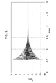
- FIG. 1 A case of closing of the switch in an out of synchronism instant can be seen in Figure 1 .
- the intensities in the three phases after synchronisation with a phase difference of 50 degrees are depicted in the figure superimposed. Due to this phase difference, the synchronous machine suffers a surge giving rise to the overcurrent such as those shown in the graph. These overcurrents are greater the greater the phase difference at the time of closing the switch and are those which can give rise to irreparable damage both in windings and in mechanical elements since the driving means suffer torques also above the nominal values.
- the present invention protects the elements of the plant and particularly the generator during the synchronisation process for synchronising to the network.
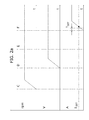
- Figure 2a shows a case of ideal synchronisation with null phase difference
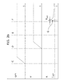
- Figure 2b shows a case of synchronisation with a specific phase difference giving rise to overcurrents.
- This value (G) represents the point in which the overcurrent protection would be triggered, the value of the intensity passing to zero instead of following the curve shown in this figure.
- a synchronous machine (1) which in turn has a synchroniser (1.1) and a voltage regulator (1.2). This synchronous machine (1) will provide electric power to the electric network (2).
- the synchronous machine (1) is moved by mechanical driving means (3), preferably a turbine, connected to the synchronous machine (1) through a movement drive shaft (4).
- the synchronous machine (1) is responsible for transforming the mechanical power reaching it from the driving means (3) into electric power.
- the synchronous machine has control means (5) for controlling the mechanical driving means (3) to regulate the mechanical power delivered by the mechanical driving means (3).
- control means (5) are used for example to increase the active power set point delivered after closing the switch (6) up to the assigned values.
- the control means (5) are means for regulating the entry of steam into the turbine.
- a switch (6) is used for synchronising the synchronous machine (1) with the electric network (2) where in this embodiment the closing is carried out by means of an actuator (7) suitable for opening or closing said switch (6).
- the plant according to this embodiment further comprises a process control unit (9), measuring means (8) for measuring the intensity delivered from the synchronous machine (1) to the electric network (2) arranged at least in one of the phases with an intensity reading signal output connected to the process control unit (9); where, in turn, the process control unit (9) has an output connected to the actuator (7) to command opening the switch (6).
- a process control unit (9) measuring means (8) for measuring the intensity delivered from the synchronous machine (1) to the electric network (2) arranged at least in one of the phases with an intensity reading signal output connected to the process control unit (9); where, in turn, the process control unit (9) has an output connected to the actuator (7) to command opening the switch (6).
- the plant additionally comprises detection means (10) for detecting the closing of the switch (6) the output of which is connected to the process control unit (9).
- the central processing unit (9) is a programmable unit which is suitable for carrying out the following steps:
- the central processing unit (9) is formed by a logic gate circuit the design of which gives rise to a circuit suitable for carrying out the steps described above.
- the overcurrent protection is an inverse time protection.
- the operation or triggering of the inverse time overcurrent protection is inversely related to the detected current intensity, that is, the greater the current intensity the faster the protection is activated. This has the technical advantage that the method is capable of protecting when there are greater intensities in a shorter time and there is therefore less damage in the synchronous machine (1).
- this protection is carried out in an inverse time relay.
- the overcurrent protection is implemented by means of the central processing unit (9).
- the overcurrent protection triggers the group switch (6) when a series of triggering conditions which depend on the detected level of intensity are met.
- This condition and action on the switch (6) are configured in a central processing unit (9) the programming of which allows generating an output which acts on the actuator (7).
- This has the technical advantage of having a programmable unit the function of which is easily reprogrammable when triggering conditions change without having to physically modify any device.
- the overcurrent protection arranged in at least the phase having measuring means (8) for measuring the current verifies that:
- This central processing unit (9) is suitable so that the signal coming from the detection means (10) for detecting the closing of the switch (6) is logic 1 when the switch is open and zero when it is closed. If the switch (6) behaves inversely, then the central processing unit (9) has an inverter before the input of the gate (AND).
Landscapes
- Engineering & Computer Science (AREA)
- Power Engineering (AREA)
- Protection Of Generators And Motors (AREA)
- Control Of Eletrric Generators (AREA)
Abstract
Description
- The present invention relates to a method of electrical protection of a synchronous machine, for example a generator, and an electric power generation plant for powering an electric network comprising an electrical protection for synchronising a synchronous machine to an electric network. The method of protection according to the invention establishes a period in which the electrical protection is active and also the instant in which said protection ceases to be active to offer the protection necessary and at the same time not prevent the correct increase of charge.
- Electric generators can be withdrawn from service for various reasons, such as the variation of charge, its own maintenance or emergency situations, among others. Each time putting a generator in service again is desired, it must be synchronised with the network before proceeding to close the switch. This synchronisation implies that the voltage in generator terminals has amplitude and frequency equal or similar to that of the network voltage in the connection point, as well as a practically null phase difference. The sequence of the three-phase voltage system of the generator must further be identical to that of the electric network.
- An incorrect synchronisation operation can involve serious damage to the generator, to the turbine or to the main transformer, caused by the electric and mechanical surges created, as well as introducing serious disruptions in the network. The severity of the damage caused by closing the switch in out of synchronism conditions depends on the short-circuit current in the connection point with the power network and mainly on the phase difference between the network voltage and on the machine to be coupled. The greater this short-circuit current and the phase difference are, the greater the current which will flow through each phase of the generator will be.
- Currently, coupling operations for coupling generators to the electric network can be performed manually or automatically by means of automatic synchronisers. When the electric generator rotates with voltage in its terminals, the possible operating errors, the existence of faulty devices or even that the synchroniser is out of service, can close the group switch in out of synchronism conditions. Given that there is no specific protection function for the coupling process in current generator electrical protection systems, the surges caused by the coupling operations without synchronism conditions cannot be instantly cleared by any other existing protection function and the consequences can be very severe.
- A protection function exists in the generator electrical protection systems referred to as 50/27, "Inadvertent energisation". Its purpose is to prevent the damage caused by closing the group switch when the synchronous machine is stopped and/or de-energised. When the group switch is closed while the generator is out of service, the latter starts working as an asynchronous motor. This operation causes an accelerated overheating of the rotor and can cause very severe mechanical damage to the turbine.
- The 50/27 protection function is based on an instantaneous overcurrent protection which is active while the voltage in generator terminals is less than approximately 80%, such that in the event of detecting an overcurrent greater than a current threshold value (around 10% of the nominal intensity) while the voltage is less than the activation voltage threshold (the mentioned 80% for example), the protection function detects that the switch has been closed inadequately. When the voltage exceeds the deactivation voltage threshold of the described protection function, it is disabled after a time, therefore, in the event of coupling without synchronism conditions, the 50/27 function does not solve the problem.
- Overcurrent protectors are not incorporated in electric power generation plants since, in the event of a short-circuit in the network, the plant has to keep supplying power without decoupling so that the overcurrent protection systems distributed throughout the network isolate the sections where the short-circuit is produced, maintaining service in the rest of the network.
- The main technical problem which the invention solves is that of finding a specific protection function for the process of coupling synchronous machines to the electric network.
- The present invention solves the problem described above by means of a method of protection of a synchronous machine according to
claim 1 and an electric power generation plant for powering an electric network according toclaim 4. - A first inventive aspect is a method of electrical protection of a synchronous machine in synchronisation when said synchronous machine is coupled with an electric network, at least the following elements intervening in the synchronisation:
- mechanical driving means, preferably a turbine, connected to the synchronous machine through a movement drive shaft where this synchronous machine has a synchroniser and a voltage regulator,
- control means for controlling the mechanical driving means to regulate the amount of power delivered by the mechanical driving means,
- a switch for electrically connecting the synchronous machine and the electric network,
- an actuator suitable for opening the switch,
- a process control unit,
- measuring means for measuring the intensity delivered from the synchronous machine to the electric network arranged at least in one of the phases with an intensity reading signal output connected to the process control unit; and in turn, the process control unit has an output connected to the actuator to command opening the switch,
- detection means for detecting the closing of the switch the output of which is connected to the process control unit, where the synchronisation process for synchronising the synchronous machine to the electric network comprises the following steps carried out sequentially:
- a) activating the mechanical driving means with the switch open so that the synchronous machine reaches the nominal rotation speed,
- b) powering the excitation winding of the synchronous machine by connecting its voltage regulator,
- c) starting the synchroniser once the nominal voltage is reached in the armature of the synchronous machine such that once synchronism is reached, the synchroniser commands closing the switch.
- The method of electrical protection acts on a system of synchronisation of a synchronous machine to an electric network. A method of synchronisation, as occurs in the state of the art, is performed in a scenario comprising elements such as a turbo type machine, which can be any type of turbine, which is controlled for example with water or water vapour the pressure of which controls the rotation speed of the turbine. The turbine transfers torque to the synchronous machine through a shaft. The synchronous machine comprises a synchroniser and a voltage regulator. The synchroniser acts such that when the machine and network voltages have the same amplitude, the same frequency and a practically null phase difference, it sends the command to close the group switch.
- In the event of a fault of this synchroniser, or due to human error, the group switch can be closed in out of synchronism conditions. It is for this reason that a protection like that of the present invention is necessary.
- To carry out the protection, the invention assures that the overcurrent protection is only active for a limited time period during the synchronisation and acts in the manner detailed below using the following elements: an actuator suitable for opening the switch, a process control unit, which can be processing means, measuring means for measuring the intensity delivered from the synchronous machine to the electric network arranged at least in one of the phases with an intensity reading signal output connected to the process control unit; and in turn, the process control unit has an output connected to the actuator to command opening the switch. Lastly there are detection means for detecting the closing of the switch which in one embodiment can be an intensity detector at the output of the synchronous machine or any closed switch detection means.
- To assure that the technical problem considered is solved, the method of protection is characterised in that:
- steps a) to d) are additionally carried out by means of the central processing unit:
- a) setting an adjustment intensity threshold value ISET less than the value of the assigned intensity of the synchronous machine,
- b) providing overcurrent protection in at least the phase having measuring means for measuring the intensity and
where this overcurrent protection is suitable for being activated and deactivated by means of the central processing unit, and where it is further suitable for opening the switch when there is an overcurrent value greater than ISET aborting the synchronisation process, - c) assuring that the protection is active before the instant of closing the switch by means of the central processing unit,
- d) once the closing of the switch is detected by the central processing unit, determining a time TSET verifying that, in a start-up process with intensity increase up to the nominal value without synchronisation faults, the intensity ISET is reached in an instant T>TSET, and where during the time interval TSET overcurrent protection is maintained active, being deactivated once the instant TSET is exceeded; and increasing the power in the mechanical driving means to reach the assigned intensity by means of regulating the control means for controlling the mechanical driving means.
- Given that after closing the switch power starts to be transferred from the synchronous machine, the latter being controlled by the control means for controlling the mechanical driving means, for example water vapour, it is at this time when an overcurrent will occur in the event of there not being synchronism conditions. The critical moment is therefore the moment in which the closing of the automatic switch occurs. The invention maintains supervision during an limited time period TSET. The presence of overcurrent protection cannot interfere in the start-up process which is carried out from the synchronism operation until the synchronous machine is delivering to the network a current value equal to its assigned value. The invention prevents the presence of the protection from interfering in this start-up process by deactivating the protection in an adequate instant of time. This instant of time is prior to the instant in which the increasing intensity in a normal start-up process reaches the current value at which the protection would act. If this were not so, the overcurrent protection would be triggered before reaching the assigned current value.
- In the event of detecting current greater than ISET, before an estimated time TSET elapses after closing the automatic switch, the synchronisation operation is aborted by sending an opening command. In the event that this time TSET has passed and no current greater than ISET is detected, it is considered that the synchronisation has been performed correctly and the power increase process can be continued, increasing the power delivered to the network from the machine up to the assigned value. The protection is deactivated in the instant TSET after closing the automatic switch since it is considered that the synchronisation is correct if the current of the machine does not exceed ISET in this period.
- The difference of this method of protection compared to the methods of protection of the state of the art is that it protects the machine only at the time of synchronisation. Therefore, if, for example, an overcurrent occurs due to a short-circuit in normal operating conditions in any point of the network, other means of protection would act without the protection of the invention intervening.
- The present invention allows maintaining a synchronous machine in service even when there is a short-circuit in one point of the network since the protection which the invention uses is deactivated. Other means of protection will act, for example, isolating the point of the network where the short-circuit occurs.
- A second inventive aspect is an electric power generation plant for powering an electric network comprising the following elements:
- synchronous machine comprising a synchroniser and a voltage regulator,
- mechanical driving means connected to the synchronous machine through a movement drive shaft,
- control means for controlling the mechanical driving means to regulate the amount of power delivered by the mechanical driving means,
- a switch for electrically connecting the synchronous machine and the electric network,
- an actuator suitable for opening the switch,
- a process control unit,
- measuring means for measuring the intensity delivered from the synchronous machine to the electric network arranged at least in one of the phases with an intensity reading signal output in communication with the process control unit; and in turn, the process control unit has an output in communication with the actuator to allow opening the switch,
- detection means for detecting the closing of the switch the
output of which is connected to the process control unit, characterised in that it additionally comprises an overcurrent protection in at least the phase having measuring means for measuring the intensity where: - the protection is configured with a trigger intensity value ISET less than the value of the nominal intensity of the synchronous machine,
- the protection is configured for being activated and deactivated by means of the central processing unit, and in that the central processing unit is suitable for carrying out a method according to steps c) and d) of the first inventive aspect.
- The generation plant comprises elements configured such that the protection is calibrated to the value ISET to set an intensity threshold value such that it triggers the group switch if this threshold is exceeded in an instant of time prior to that set by TSET from closing the switch. The triggering and the triggering conditions are controlled by the central processing unit. This central processing unit does not necessarily have to be a programmable microprocessor but it can be configured by means of logic gates and a timer where the behaviour and design values (ISET, TSET) are set during the design of said central processing unit.
- All the technical features described in this specification (including the claims, description and drawings) can be combined in any combination, except the combinations of such mutually excluding features.
- These and other features and advantages of the invention will be more clearly understood from the following detailed description of a preferred embodiment, given only as an illustrative and non-limiting example with reference to the attached drawings.
-
Figure 1 shows a graph depicting the evolution of the intensities of the armature of a synchronous machine in the event of closing the switch in an out of synchronism instant . -
Figure 2a and2b are two comparative graphs showing the evolution of the rotation speed of the synchronous machine over time, the voltage in the winding of the machine and the current in one of the phases.Figure 2a shows an ideal start-up situation where the current at the time of closing the automatic switch is null; andFigure 2b shows a start-up out of synchronism conditions in which the described protection would act using a system according to the invention. -
Figure 3 shows a schematic depiction of an embodiment of the invention of an electric power generation plant for powering an electric network. -
Figure 4 shows a schematic depiction of an embodiment of the central processing unit implemented by means of logic gates. - The invention comprises a method of overcurrent protection of a synchronous machine (1) according to
claim 1 and an electric power generation plant for powering an electric network (2) according toclaim 4. The dependent claims describe particular embodiments of the invention. - A case of closing of the switch in an out of synchronism instant can be seen in
Figure 1 . The intensities in the three phases after synchronisation with a phase difference of 50 degrees are depicted in the figure superimposed. Due to this phase difference, the synchronous machine suffers a surge giving rise to the overcurrent such as those shown in the graph. These overcurrents are greater the greater the phase difference at the time of closing the switch and are those which can give rise to irreparable damage both in windings and in mechanical elements since the driving means suffer torques also above the nominal values. - The present invention protects the elements of the plant and particularly the generator during the synchronisation process for synchronising to the network.
- Two situations can be seen in
Figures 2a and2b :Figure 2a shows a case of ideal synchronisation with null phase difference andFigure 2b shows a case of synchronisation with a specific phase difference giving rise to overcurrents. When the synchronisation operation is done in phase the process follows the following steps: - A turbine (3) starts to drive the rotor of the synchronous machine (
Figure 2a ) in the instant indicated in the graph as C. - Once the nominal rotation speed (rpm) is reached, the voltage is increased in the phases of the synchronous machine (1) carrying out the control of the voltage through the voltage regulator (1.1) of the synchronous machine (1). It can be seen that the voltage in the synchronous machine has already reached the nominal value in the instant of time identified with the letter D.
- The synchronous machine (1) in this embodiment has a synchroniser (1.2) responsible for establishing the connection at the time in which said synchroniser considers that the voltage in the synchronous machine and in the network (2) have the same modulus and frequency and are further in phase (always taking into account specific tolerance threshold values). In the instant identified with the letter E, the synchroniser (1.2) is activated and waits to detect that the conditions for the synchronism are present.
- Once these conditions for the synchronism are detected the synchroniser (1.2) commands closing a switch (6). The instant in which the switch (6) is closed is identified with the letter F.
- In an instant of time prior to F an overcurrent protection suitable for opening the switch in case the current exceeds a pre-set threshold value ISET less than the nominal intensity is activated.
- In the instant of closing the switch (6) a timer (12) (
Figure 4 ) which measures a time TSET is activated. After this time TSET has passed the overcurrent protection is deactivated. The time period TSET is such that in a start-up process with an progressive intensity increase up to the assigned value without synchronisation faults the intensity ISET is reached in an instant T>TSET. - In this embodiment, after the instant F the user starts to increase the power delivered to the network (2) from the synchronous machine (1). If a current value greater than ISET is not exceeded in a time less than TSET, it is considered that the synchronisation has been correct and the power delivered to the network (2) continues to be increased gradually until reaching the nominal value. These synchronism conditions without overcurrent problems are the shown in
Figure 2a . - In contrast, when synchronisation is not done in conditions of equal voltage, frequency and in phase, the evolution of the system is the same as that shown in
Figure 2a up to instant F which is when the closing of the switch (6) occurs only that now, due to a fault, the modulus or the frequencies of the machine and the network voltages are not equal, or the phase difference is not null (2) and therefore overcurrents occur (Figure 2b ). - As has been described, the overcurrent protection suitable for opening the switch (6) in the event of the intensity exceeding a pre-set threshold value ISET less than the assigned intensity has been activated before closing the switch (6).
- Likewise, a timer (12) (
Figure 4 ) which measures a time TSET is activated at the time of closing the switch (6) so that if the overcurrent protection has not acted when this instant TSET has been reached, it is deactivated,. - A high overcurrent exceeding the value of ISET occurs in the first instants when the synchronous machine (1) is not in synchronism conditions. The graph shown in
Figure 2b depicts a current peak which decreases over time. According to the invention, given that in the time interval TSET the overcurrent protection is activated, it would be triggered by opening the automatic switch (6). The value of said overcurrent is greater the greater the phase difference between the synchronous machine and network voltages. - An intensity value (G) greater than ISET, corresponding to an instant of time comprised in the interval TSET is indicated in
Figure 2b . This value (G) represents the point in which the overcurrent protection would be triggered, the value of the intensity passing to zero instead of following the curve shown in this figure. - The elements which a plant implementing a method of protection according to an embodiment of the invention comprises are schematically shown in
Figure 3 . - In this embodiment there is a synchronous machine (1) which in turn has a synchroniser (1.1) and a voltage regulator (1.2). This synchronous machine (1) will provide electric power to the electric network (2).
- In turn, the synchronous machine (1) is moved by mechanical driving means (3), preferably a turbine, connected to the synchronous machine (1) through a movement drive shaft (4). The synchronous machine (1) is responsible for transforming the mechanical power reaching it from the driving means (3) into electric power.
- The synchronous machine has control means (5) for controlling the mechanical driving means (3) to regulate the mechanical power delivered by the mechanical driving means (3). These control means (5) are used for example to increase the active power set point delivered after closing the switch (6) up to the assigned values. In the event of the driving means (3) being a steam turbine, the control means (5) are means for regulating the entry of steam into the turbine.
- A switch (6) is used for synchronising the synchronous machine (1) with the electric network (2) where in this embodiment the closing is carried out by means of an actuator (7) suitable for opening or closing said switch (6).
- The plant according to this embodiment further comprises a process control unit (9), measuring means (8) for measuring the intensity delivered from the synchronous machine (1) to the electric network (2) arranged at least in one of the phases with an intensity reading signal output connected to the process control unit (9); where, in turn, the process control unit (9) has an output connected to the actuator (7) to command opening the switch (6).
- The plant additionally comprises detection means (10) for detecting the closing of the switch (6) the output of which is connected to the process control unit (9). According to one embodiment, the central processing unit (9) is a programmable unit which is suitable for carrying out the following steps:
- a) setting an adjustment intensity value ISET less than the value of the assigned intensity of the synchronous machine,
- b) providing overcurrent protection in at least the phase having measuring means for measuring the intensity and where this overcurrent protection is suitable for being activated and deactivated by means of the central processing unit, and where it is further suitable for opening the switch when there is an overcurrent value greater than ISET aborting the synchronisation process,
- c) assuring that the protection is active before closing the switch by means of the central processing unit,
- d) once the closing of the switch is detected by the central processing unit a time TSET is determined verifying that, in a start-up process with intensity increase up to the nominal value without synchronisation faults, the intensity ISET is reached in an instant T>TSET, and where during the time interval TSET overcurrent protection is maintained active, being deactivated once the instant TSET is exceeded; and increasing the set point power in the mechanical driving means to reach the nominal intensity by means of regulating the control means for controlling the mechanical driving means.
- In another embodiment, the central processing unit (9) is formed by a logic gate circuit the design of which gives rise to a circuit suitable for carrying out the steps described above.
- In one embodiment, the overcurrent protection is an inverse time protection. The operation or triggering of the inverse time overcurrent protection is inversely related to the detected current intensity, that is, the greater the current intensity the faster the protection is activated. This has the technical advantage that the method is capable of protecting when there are greater intensities in a shorter time and there is therefore less damage in the synchronous machine (1). In one embodiment, this protection is carried out in an inverse time relay.
- In one embodiment, the overcurrent protection is implemented by means of the central processing unit (9). The overcurrent protection triggers the group switch (6) when a series of triggering conditions which depend on the detected level of intensity are met. This condition and action on the switch (6) are configured in a central processing unit (9) the programming of which allows generating an output which acts on the actuator (7). This has the technical advantage of having a programmable unit the function of which is easily reprogrammable when triggering conditions change without having to physically modify any device.
- In any of the embodiments, the overcurrent protection arranged in at least the phase having measuring means (8) for measuring the current thus verifies that:
- the protection is configured with a trigger intensity value ISET less than the nominal intensity of the synchronous machine (1),
- the protection is configured for being activated and deactivated by means of the central processing unit (9).
In one embodiment of the plant, the central processing unit (9) is as shown inFigure 4 , where said unit comprises processing means implemented as a set of logic gates where the inputs are - the output of the detection means (10) for detecting the closing of the switch (6),
- the output of the measuring means (8) for measuring the intensity in at least one of the phases,
where the output towards the actuation means (7) is the logical product (AND) of the two following signals: - the comparison of the signal coming from the measuring means (8) for measuring the intensity with a threshold ISET; and,
- the signal coming from the detection means (10) for detecting the closing of the switch (6) delayed for a time TSET.
- This central processing unit (9) is suitable so that the signal coming from the detection means (10) for detecting the closing of the switch (6) is
logic 1 when the switch is open and zero when it is closed. If the switch (6) behaves inversely, then the central processing unit (9) has an inverter before the input of the gate (AND).
Claims (7)
- A method of electrical protection of a synchronous machine (1) in the synchronization when said synchronous machine (1) is coupled with an electric network (2), at least the following elements intervening in the synchronization:• mechanical driving means (3), preferably a turbine, connected to the synchronous machine (1) through a movement drive shaft (4) where this synchronous machine (1) has a synchroniser (1.1) and a voltage regulator (1.2),• control means (5) for controlling the mechanical driving means (3) to regulate the amount of power delivered by the mechanical driving means (3),• a switch (6) for electrically connecting the synchronous machine (1) and the electric network (2),• an actuator (7) suitable for opening the switch (6),• a process control unit (9),• measuring means (8) for measuring the intensity delivered from the synchronous machine (1) to the electric network (2) arranged at least in one of the phases with an intensity reading signal output connected to the process control unit (9); and in turn, the process control unit (9) has an output connected to the actuator (7) to command opening the switch (6),• detection means (10) for detecting the closing of the switch (6) the output of which is connected to the process control unit (9),where the synchronisation process for synchronising the synchronous machine (1) to the electric network (2) comprises the following steps carried out sequentially:a) activating the mechanical driving means (3) with the switch (6) open so that the synchronous machine (1) reaches the nominal rotation speed,b) powering the excitation winding of the synchronous machine (1) by connecting its voltage regulator (1.2),c) starting the synchroniser (1.1) once the nominal voltage is reached in the armature of the synchronous machine (1) such that once synchronism is reached, the synchroniser (1.1) commands closing the switch (6),characterised in that• steps a) to d) are additionally carried out by means of the central processing unit (9):a) setting an adjustment intensity threshold value ISET less than the value of the assigned intensity of the synchronous machine (1),b) providing overcurrent protection in at least the phase having measuring means (8) for measuring the intensity and where this overcurrent protection is suitable for being activated and deactivated by means of the central processing unit (9), and where it is further suitable for opening the switch (6) when there is an overcurrent value greater than ISET aborting the synchronisation process,c) assuring that the protection is active before the instant of closing the switch (6) by means of the central processing unit (9),d) once the closing of the switch (6) is detected by the central processing unit (9), determining a time TSET verifying that, in a start-up process with intensity increase up to the nominal value without synchronisation faults, the intensity ISET is reached in an instant T>TSET, and where during the time interval TSET overcurrent protection is maintained active, being deactivated once the instant TSET is exceeded; and,• increasing the power in the mechanical driving means to reach the assigned intensity by means of regulating the control means (5) for controlling the mechanical driving means (3).
- The method according to claim 1, characterised in that the overcurrent protection is an inverse time protection.
- The method according to claims 1 or 2, characterised in that the overcurrent protection is implemented by means of the central processing unit (9).
- An electric power generation plant for powering an electric network (2) comprising the following elements:• synchronous machine (1) comprising a synchroniser (1.1) and a voltage regulator (1.2),• mechanical driving means (3) connected to the synchronous machine (1) through a movement drive shaft (4),• control means (5) for controlling the mechanical driving means (3) to regulate the amount of power delivered by the mechanical driving means (3),• a switch (6) for electrically connecting the synchronous machine (1) and the electric network (2),• an actuator (7) suitable for opening the switch (6),• a process control unit (9),• measuring means (8) for measuring the intensity delivered from the synchronous machine (1) to the electric network (2) arranged at least in one of the phases with an intensity reading signal output in communication with the process control unit (9); and in turn, the process control unit (9) has an output in communication with the actuator (7) to allow opening the switch (6),• detection means (10) for detecting the closing of the switch (6) the output of which is connected to the process control unit (9),characterised in that it additionally comprises an overcurrent protection in at least the phase having measuring means (8) for measuring the intensity where:• the protection is configured with a trigger intensity value ISET less than the value of the assigned intensity of the synchronous machine (1),• the protection is configured for being activated and deactivated by means of the central processing unit (9),
and in that the central processing unit (9) is suitable for carrying out a method according to steps c) and d) of claim 1. - The plant according to claim 4, characterised in that the overcurrent protection is an inverse time protection.
- The plant according to claims 4 or 5, characterised in that the central processing unit (9) is suitable for carrying out the overcurrent protection function.
- The plant according to any of claims 4 to 6, characterised in that the central processing unit (9) comprises processing means implemented as a set of logic gates where the inputs are:• the output of the detection means (10) for detecting the closing of the switch (6),• the output of the measuring means (8) for measuring the intensity in at least one of the phases,where the output towards the actuation means (7) is the logical product (AND) of two signals:• the comparison of the signal coming from the measuring means (8) for measuring the intensity with a threshold ISET; and,• the signal coming from the detection means (10) for detecting the closing of the switch (6) delayed for a time TSET.
Priority Applications (1)
| Application Number | Priority Date | Filing Date | Title |
|---|---|---|---|
| EP12382130.8A EP2648301B1 (en) | 2012-04-02 | 2012-04-02 | Method of electrical protection of a synchronous machine and electric power generation plant for powering an electric network |
Applications Claiming Priority (1)
| Application Number | Priority Date | Filing Date | Title |
|---|---|---|---|
| EP12382130.8A EP2648301B1 (en) | 2012-04-02 | 2012-04-02 | Method of electrical protection of a synchronous machine and electric power generation plant for powering an electric network |
Publications (2)
| Publication Number | Publication Date |
|---|---|
| EP2648301A1 true EP2648301A1 (en) | 2013-10-09 |
| EP2648301B1 EP2648301B1 (en) | 2016-05-04 |
Family
ID=46317309
Family Applications (1)
| Application Number | Title | Priority Date | Filing Date |
|---|---|---|---|
| EP12382130.8A Not-in-force EP2648301B1 (en) | 2012-04-02 | 2012-04-02 | Method of electrical protection of a synchronous machine and electric power generation plant for powering an electric network |
Country Status (1)
| Country | Link |
|---|---|
| EP (1) | EP2648301B1 (en) |
Citations (3)
| Publication number | Priority date | Publication date | Assignee | Title |
|---|---|---|---|---|
| GB2205207A (en) * | 1987-05-29 | 1988-11-30 | Richard Dudley Payne | Electrical generator control system |
| US5390068A (en) * | 1988-05-09 | 1995-02-14 | Onan Corporation | Microprocessor based integrated generator set controller apparatus and method |
| US20100010684A1 (en) * | 2007-05-07 | 2010-01-14 | Lorenz Rick A | Protection techniques for an electric power system |
-
2012
- 2012-04-02 EP EP12382130.8A patent/EP2648301B1/en not_active Not-in-force
Patent Citations (3)
| Publication number | Priority date | Publication date | Assignee | Title |
|---|---|---|---|---|
| GB2205207A (en) * | 1987-05-29 | 1988-11-30 | Richard Dudley Payne | Electrical generator control system |
| US5390068A (en) * | 1988-05-09 | 1995-02-14 | Onan Corporation | Microprocessor based integrated generator set controller apparatus and method |
| US20100010684A1 (en) * | 2007-05-07 | 2010-01-14 | Lorenz Rick A | Protection techniques for an electric power system |
Also Published As
| Publication number | Publication date |
|---|---|
| EP2648301B1 (en) | 2016-05-04 |
Similar Documents
| Publication | Publication Date | Title |
|---|---|---|
| EP2477294B1 (en) | Overvoltage limiter in an aircraft electrical power generation system | |
| EP3032684B1 (en) | Power generation system and method with resistive braking capability | |
| EP2465193B1 (en) | A protection arrangement of an electric power system | |
| JP2006514523A5 (en) | ||
| EP3361622A1 (en) | Driving control device and method for yaw electrmotor of wind power generation set | |
| JP2006514523A (en) | Control method during failure of power grid of wind turbine generator connected to high voltage power grid and apparatus for implementing the method | |
| DK2087571T3 (en) | CONTROLLERS WITH CONTROLLABLE PHASE ANGLE | |
| EP3371882B1 (en) | Balancing reactive current between a dfig stator and a grid-side inverter | |
| EP2293432A1 (en) | Static exciter of an electric generator, method for retrofitting and method for operating the same | |
| EP2899824B1 (en) | Over-voltage prevention device and current rectifying circuit | |
| JP6495627B2 (en) | Power generation system and method having fault ride-through capability | |
| EP3255780B1 (en) | High voltage dc power generating system including selectively removable neutral node | |
| CN104079005B (en) | Steam turbine governing system for maintaining synchronization and process for performing the same | |
| CN112689932B (en) | Method for controlling a renewable power generation device during a network ground fault | |
| KR101436998B1 (en) | Blade angle adjustment drive for a wind power plant | |
| EP3476742B1 (en) | Wound field generator overvoltage prevention | |
| CN107240912B (en) | Overvoltage Protection Device for Variable Speed Pumping Power Generation System | |
| WO2012134458A1 (en) | Dynamic braking and low voltage ride through | |
| EP2648301B1 (en) | Method of electrical protection of a synchronous machine and electric power generation plant for powering an electric network | |
| KR101699363B1 (en) | Motor protection relay and method for driving motor of motor protection relay | |
| RU2472006C2 (en) | Steam turbine power plant control method and device | |
| JP2020065437A (en) | Overvoltage prevention apparatus for adjustable speed pumped storage power generation system | |
| JP5101148B2 (en) | Automatic synchronization method | |
| CN104124665B (en) | Electric generator shunt tripping turbine controlling method | |
| Hunswadkar et al. | Considerations and methods for an effective fast bus transfer system |
Legal Events
| Date | Code | Title | Description |
|---|---|---|---|
| PUAI | Public reference made under article 153(3) epc to a published international application that has entered the european phase |
Free format text: ORIGINAL CODE: 0009012 |
|
| AK | Designated contracting states |
Kind code of ref document: A1 Designated state(s): AL AT BE BG CH CY CZ DE DK EE ES FI FR GB GR HR HU IE IS IT LI LT LU LV MC MK MT NL NO PL PT RO RS SE SI SK SM TR |
|
| AX | Request for extension of the european patent |
Extension state: BA ME |
|
| 17P | Request for examination filed |
Effective date: 20140409 |
|
| RBV | Designated contracting states (corrected) |
Designated state(s): AL AT BE BG CH CY CZ DE DK EE ES FI FR GB GR HR HU IE IS IT LI LT LU LV MC MK MT NL NO PL PT RO RS SE SI SK SM TR |
|
| GRAP | Despatch of communication of intention to grant a patent |
Free format text: ORIGINAL CODE: EPIDOSNIGR1 |
|
| RIC1 | Information provided on ipc code assigned before grant |
Ipc: H02P 9/04 20060101ALI20150518BHEP Ipc: H02J 3/42 20060101ALI20150518BHEP Ipc: H02H 7/06 20060101AFI20150518BHEP |
|
| INTG | Intention to grant announced |
Effective date: 20150608 |
|
| GRAP | Despatch of communication of intention to grant a patent |
Free format text: ORIGINAL CODE: EPIDOSNIGR1 |
|
| INTG | Intention to grant announced |
Effective date: 20151104 |
|
| GRAS | Grant fee paid |
Free format text: ORIGINAL CODE: EPIDOSNIGR3 |
|
| GRAA | (expected) grant |
Free format text: ORIGINAL CODE: 0009210 |
|
| AK | Designated contracting states |
Kind code of ref document: B1 Designated state(s): AL AT BE BG CH CY CZ DE DK EE ES FI FR GB GR HR HU IE IS IT LI LT LU LV MC MK MT NL NO PL PT RO RS SE SI SK SM TR |
|
| REG | Reference to a national code |
Ref country code: GB Ref legal event code: FG4D |
|
| REG | Reference to a national code |
Ref country code: CH Ref legal event code: EP |
|
| REG | Reference to a national code |
Ref country code: AT Ref legal event code: REF Ref document number: 797657 Country of ref document: AT Kind code of ref document: T Effective date: 20160515 |
|
| REG | Reference to a national code |
Ref country code: IE Ref legal event code: FG4D |
|
| REG | Reference to a national code |
Ref country code: DE Ref legal event code: R096 Ref document number: 602012018031 Country of ref document: DE |
|
| REG | Reference to a national code |
Ref country code: NL Ref legal event code: MP Effective date: 20160504 |
|
| REG | Reference to a national code |
Ref country code: LT Ref legal event code: MG4D |
|
| PG25 | Lapsed in a contracting state [announced via postgrant information from national office to epo] |
Ref country code: NL Free format text: LAPSE BECAUSE OF FAILURE TO SUBMIT A TRANSLATION OF THE DESCRIPTION OR TO PAY THE FEE WITHIN THE PRESCRIBED TIME-LIMIT Effective date: 20160504 Ref country code: FI Free format text: LAPSE BECAUSE OF FAILURE TO SUBMIT A TRANSLATION OF THE DESCRIPTION OR TO PAY THE FEE WITHIN THE PRESCRIBED TIME-LIMIT Effective date: 20160504 Ref country code: NO Free format text: LAPSE BECAUSE OF FAILURE TO SUBMIT A TRANSLATION OF THE DESCRIPTION OR TO PAY THE FEE WITHIN THE PRESCRIBED TIME-LIMIT Effective date: 20160804 Ref country code: LT Free format text: LAPSE BECAUSE OF FAILURE TO SUBMIT A TRANSLATION OF THE DESCRIPTION OR TO PAY THE FEE WITHIN THE PRESCRIBED TIME-LIMIT Effective date: 20160504 |
|
| REG | Reference to a national code |
Ref country code: AT Ref legal event code: MK05 Ref document number: 797657 Country of ref document: AT Kind code of ref document: T Effective date: 20160504 |
|
| PG25 | Lapsed in a contracting state [announced via postgrant information from national office to epo] |
Ref country code: SE Free format text: LAPSE BECAUSE OF FAILURE TO SUBMIT A TRANSLATION OF THE DESCRIPTION OR TO PAY THE FEE WITHIN THE PRESCRIBED TIME-LIMIT Effective date: 20160504 Ref country code: LV Free format text: LAPSE BECAUSE OF FAILURE TO SUBMIT A TRANSLATION OF THE DESCRIPTION OR TO PAY THE FEE WITHIN THE PRESCRIBED TIME-LIMIT Effective date: 20160504 Ref country code: PT Free format text: LAPSE BECAUSE OF FAILURE TO SUBMIT A TRANSLATION OF THE DESCRIPTION OR TO PAY THE FEE WITHIN THE PRESCRIBED TIME-LIMIT Effective date: 20160905 Ref country code: RS Free format text: LAPSE BECAUSE OF FAILURE TO SUBMIT A TRANSLATION OF THE DESCRIPTION OR TO PAY THE FEE WITHIN THE PRESCRIBED TIME-LIMIT Effective date: 20160504 Ref country code: ES Free format text: LAPSE BECAUSE OF FAILURE TO SUBMIT A TRANSLATION OF THE DESCRIPTION OR TO PAY THE FEE WITHIN THE PRESCRIBED TIME-LIMIT Effective date: 20160504 Ref country code: HR Free format text: LAPSE BECAUSE OF FAILURE TO SUBMIT A TRANSLATION OF THE DESCRIPTION OR TO PAY THE FEE WITHIN THE PRESCRIBED TIME-LIMIT Effective date: 20160504 Ref country code: GR Free format text: LAPSE BECAUSE OF FAILURE TO SUBMIT A TRANSLATION OF THE DESCRIPTION OR TO PAY THE FEE WITHIN THE PRESCRIBED TIME-LIMIT Effective date: 20160805 |
|
| PG25 | Lapsed in a contracting state [announced via postgrant information from national office to epo] |
Ref country code: IT Free format text: LAPSE BECAUSE OF FAILURE TO SUBMIT A TRANSLATION OF THE DESCRIPTION OR TO PAY THE FEE WITHIN THE PRESCRIBED TIME-LIMIT Effective date: 20160504 |
|
| PG25 | Lapsed in a contracting state [announced via postgrant information from national office to epo] |
Ref country code: RO Free format text: LAPSE BECAUSE OF FAILURE TO SUBMIT A TRANSLATION OF THE DESCRIPTION OR TO PAY THE FEE WITHIN THE PRESCRIBED TIME-LIMIT Effective date: 20160504 Ref country code: SK Free format text: LAPSE BECAUSE OF FAILURE TO SUBMIT A TRANSLATION OF THE DESCRIPTION OR TO PAY THE FEE WITHIN THE PRESCRIBED TIME-LIMIT Effective date: 20160504 Ref country code: CZ Free format text: LAPSE BECAUSE OF FAILURE TO SUBMIT A TRANSLATION OF THE DESCRIPTION OR TO PAY THE FEE WITHIN THE PRESCRIBED TIME-LIMIT Effective date: 20160504 Ref country code: EE Free format text: LAPSE BECAUSE OF FAILURE TO SUBMIT A TRANSLATION OF THE DESCRIPTION OR TO PAY THE FEE WITHIN THE PRESCRIBED TIME-LIMIT Effective date: 20160504 Ref country code: DK Free format text: LAPSE BECAUSE OF FAILURE TO SUBMIT A TRANSLATION OF THE DESCRIPTION OR TO PAY THE FEE WITHIN THE PRESCRIBED TIME-LIMIT Effective date: 20160504 |
|
| REG | Reference to a national code |
Ref country code: DE Ref legal event code: R097 Ref document number: 602012018031 Country of ref document: DE |
|
| PG25 | Lapsed in a contracting state [announced via postgrant information from national office to epo] |
Ref country code: AT Free format text: LAPSE BECAUSE OF FAILURE TO SUBMIT A TRANSLATION OF THE DESCRIPTION OR TO PAY THE FEE WITHIN THE PRESCRIBED TIME-LIMIT Effective date: 20160504 Ref country code: BE Free format text: LAPSE BECAUSE OF FAILURE TO SUBMIT A TRANSLATION OF THE DESCRIPTION OR TO PAY THE FEE WITHIN THE PRESCRIBED TIME-LIMIT Effective date: 20160504 Ref country code: PL Free format text: LAPSE BECAUSE OF FAILURE TO SUBMIT A TRANSLATION OF THE DESCRIPTION OR TO PAY THE FEE WITHIN THE PRESCRIBED TIME-LIMIT Effective date: 20160504 Ref country code: SM Free format text: LAPSE BECAUSE OF FAILURE TO SUBMIT A TRANSLATION OF THE DESCRIPTION OR TO PAY THE FEE WITHIN THE PRESCRIBED TIME-LIMIT Effective date: 20160504 |
|
| PLBE | No opposition filed within time limit |
Free format text: ORIGINAL CODE: 0009261 |
|
| STAA | Information on the status of an ep patent application or granted ep patent |
Free format text: STATUS: NO OPPOSITION FILED WITHIN TIME LIMIT |
|
| 26N | No opposition filed |
Effective date: 20170207 |
|
| PG25 | Lapsed in a contracting state [announced via postgrant information from national office to epo] |
Ref country code: SI Free format text: LAPSE BECAUSE OF FAILURE TO SUBMIT A TRANSLATION OF THE DESCRIPTION OR TO PAY THE FEE WITHIN THE PRESCRIBED TIME-LIMIT Effective date: 20160504 |
|
| REG | Reference to a national code |
Ref country code: DE Ref legal event code: R119 Ref document number: 602012018031 Country of ref document: DE |
|
| PG25 | Lapsed in a contracting state [announced via postgrant information from national office to epo] |
Ref country code: MC Free format text: LAPSE BECAUSE OF FAILURE TO SUBMIT A TRANSLATION OF THE DESCRIPTION OR TO PAY THE FEE WITHIN THE PRESCRIBED TIME-LIMIT Effective date: 20160504 |
|
| REG | Reference to a national code |
Ref country code: CH Ref legal event code: PL |
|
| GBPC | Gb: european patent ceased through non-payment of renewal fee |
Effective date: 20170402 |
|
| REG | Reference to a national code |
Ref country code: IE Ref legal event code: MM4A |
|
| REG | Reference to a national code |
Ref country code: FR Ref legal event code: ST Effective date: 20171229 |
|
| PG25 | Lapsed in a contracting state [announced via postgrant information from national office to epo] |
Ref country code: FR Free format text: LAPSE BECAUSE OF NON-PAYMENT OF DUE FEES Effective date: 20170502 Ref country code: DE Free format text: LAPSE BECAUSE OF NON-PAYMENT OF DUE FEES Effective date: 20171103 |
|
| PG25 | Lapsed in a contracting state [announced via postgrant information from national office to epo] |
Ref country code: CH Free format text: LAPSE BECAUSE OF NON-PAYMENT OF DUE FEES Effective date: 20170430 Ref country code: LI Free format text: LAPSE BECAUSE OF NON-PAYMENT OF DUE FEES Effective date: 20170430 Ref country code: LU Free format text: LAPSE BECAUSE OF NON-PAYMENT OF DUE FEES Effective date: 20170402 Ref country code: GB Free format text: LAPSE BECAUSE OF NON-PAYMENT OF DUE FEES Effective date: 20170402 |
|
| PG25 | Lapsed in a contracting state [announced via postgrant information from national office to epo] |
Ref country code: IE Free format text: LAPSE BECAUSE OF NON-PAYMENT OF DUE FEES Effective date: 20170402 |
|
| PG25 | Lapsed in a contracting state [announced via postgrant information from national office to epo] |
Ref country code: MT Free format text: LAPSE BECAUSE OF NON-PAYMENT OF DUE FEES Effective date: 20170402 |
|
| PG25 | Lapsed in a contracting state [announced via postgrant information from national office to epo] |
Ref country code: AL Free format text: LAPSE BECAUSE OF FAILURE TO SUBMIT A TRANSLATION OF THE DESCRIPTION OR TO PAY THE FEE WITHIN THE PRESCRIBED TIME-LIMIT Effective date: 20160504 |
|
| PG25 | Lapsed in a contracting state [announced via postgrant information from national office to epo] |
Ref country code: HU Free format text: LAPSE BECAUSE OF FAILURE TO SUBMIT A TRANSLATION OF THE DESCRIPTION OR TO PAY THE FEE WITHIN THE PRESCRIBED TIME-LIMIT; INVALID AB INITIO Effective date: 20120402 |
|
| PG25 | Lapsed in a contracting state [announced via postgrant information from national office to epo] |
Ref country code: BG Free format text: LAPSE BECAUSE OF FAILURE TO SUBMIT A TRANSLATION OF THE DESCRIPTION OR TO PAY THE FEE WITHIN THE PRESCRIBED TIME-LIMIT Effective date: 20160504 |
|
| PG25 | Lapsed in a contracting state [announced via postgrant information from national office to epo] |
Ref country code: CY Free format text: LAPSE BECAUSE OF NON-PAYMENT OF DUE FEES Effective date: 20160504 |
|
| PG25 | Lapsed in a contracting state [announced via postgrant information from national office to epo] |
Ref country code: MK Free format text: LAPSE BECAUSE OF FAILURE TO SUBMIT A TRANSLATION OF THE DESCRIPTION OR TO PAY THE FEE WITHIN THE PRESCRIBED TIME-LIMIT Effective date: 20160504 |
|
| PG25 | Lapsed in a contracting state [announced via postgrant information from national office to epo] |
Ref country code: TR Free format text: LAPSE BECAUSE OF FAILURE TO SUBMIT A TRANSLATION OF THE DESCRIPTION OR TO PAY THE FEE WITHIN THE PRESCRIBED TIME-LIMIT Effective date: 20160504 |
|
| PG25 | Lapsed in a contracting state [announced via postgrant information from national office to epo] |
Ref country code: IS Free format text: LAPSE BECAUSE OF FAILURE TO SUBMIT A TRANSLATION OF THE DESCRIPTION OR TO PAY THE FEE WITHIN THE PRESCRIBED TIME-LIMIT Effective date: 20160904 |