EP2648202A1 - Circuit breaker - Google Patents
Circuit breaker Download PDFInfo
- Publication number
- EP2648202A1 EP2648202A1 EP13161682.3A EP13161682A EP2648202A1 EP 2648202 A1 EP2648202 A1 EP 2648202A1 EP 13161682 A EP13161682 A EP 13161682A EP 2648202 A1 EP2648202 A1 EP 2648202A1
- Authority
- EP
- European Patent Office
- Prior art keywords
- arcing
- circuit breaker
- arc
- contact
- pressure chamber
- Prior art date
- Legal status (The legal status is an assumption and is not a legal conclusion. Google has not performed a legal analysis and makes no representation as to the accuracy of the status listed.)
- Withdrawn
Links
Images


Classifications
-
- H—ELECTRICITY
- H01—ELECTRIC ELEMENTS
- H01H—ELECTRIC SWITCHES; RELAYS; SELECTORS; EMERGENCY PROTECTIVE DEVICES
- H01H33/00—High-tension or heavy-current switches with arc-extinguishing or arc-preventing means
- H01H33/02—Details
- H01H33/04—Means for extinguishing or preventing arc between current-carrying parts
- H01H33/08—Stationary parts for restricting or subdividing the arc, e.g. barrier plate
-
- H—ELECTRICITY
- H01—ELECTRIC ELEMENTS
- H01H—ELECTRIC SWITCHES; RELAYS; SELECTORS; EMERGENCY PROTECTIVE DEVICES
- H01H33/00—High-tension or heavy-current switches with arc-extinguishing or arc-preventing means
- H01H33/70—Switches with separate means for directing, obtaining, or increasing flow of arc-extinguishing fluid
- H01H33/7015—Switches with separate means for directing, obtaining, or increasing flow of arc-extinguishing fluid characterised by flow directing elements associated with contacts
- H01H33/7084—Switches with separate means for directing, obtaining, or increasing flow of arc-extinguishing fluid characterised by flow directing elements associated with contacts characterised by movable parts influencing the gas flow
-
- H—ELECTRICITY
- H01—ELECTRIC ELEMENTS
- H01H—ELECTRIC SWITCHES; RELAYS; SELECTORS; EMERGENCY PROTECTIVE DEVICES
- H01H1/00—Contacts
- H01H1/12—Contacts characterised by the manner in which co-operating contacts engage
- H01H1/36—Contacts characterised by the manner in which co-operating contacts engage by sliding
- H01H1/38—Plug-and-socket contacts
- H01H1/385—Contact arrangements for high voltage gas blast circuit breakers
-
- H—ELECTRICITY
- H01—ELECTRIC ELEMENTS
- H01H—ELECTRIC SWITCHES; RELAYS; SELECTORS; EMERGENCY PROTECTIVE DEVICES
- H01H33/00—High-tension or heavy-current switches with arc-extinguishing or arc-preventing means
- H01H33/02—Details
- H01H33/28—Power arrangements internal to the switch for operating the driving mechanism
- H01H33/30—Power arrangements internal to the switch for operating the driving mechanism using fluid actuator
- H01H33/32—Power arrangements internal to the switch for operating the driving mechanism using fluid actuator pneumatic
Definitions
- the present invention relates to a circuit breaker for a medium or high-voltage electrical circuit. Furthermore, the invention relates to a method for circuit interruption by means of such a circuit breaker and the use of such a circuit breaker in a medium or high-voltage power transmission or distribution network. Also, the invention relates to a power transmission or distribution network comprising such a circuit breaker.
- Prior art circuit breakers can comprise compressed fluids (i.e. gases and/or liquids) as energy reservoirs and piston mechanisms as actuators.
- the stored drive energy is in general used for both mechanical actuation (e.g. separation) of electrical contacts and for pressure build-up in an arc extinguishing fluid.
- nominal contacts i.e. medium or high-voltage contacts that are used during normal, i.e., non-tripping operation
- arcing contacts i.e. medium or high-voltage contacts that are used during tripping of the circuit
- a plasma arc is formed between the already separated arcing contacts.
- this plasma arc between the arcing contacts is purged by a flow of arc extinguishing fluid during a natural induced zero crossing of the current (i.e. in an AC network) or during an artificially induced zero crossing of the current (i.e. in a DC network) through the arcing contacts.
- high blowing pressures are necessary in the arc extinguishing fluid. If the arc extinguishing fluid is not pre-pressurized, e.g.
- the necessary build-up of pressure in the arc extinguishing fluid normally takes place by means of a compression of a gaseous volume of the arc extinguishing fluid (so-called “puffer” technology) in a way similar to handheld pumps for bicycles.
- the circuit breaker is designed such that additional pressure can be generated in the arc extinguishing fluid during the high current arcing phase. This extra pressure is then used for arc interruption at current zero (so-called "self-blast” technology).
- US 5,187,339 discloses a high-voltage circuit breaker comprising a first compartment with pressurized SF6 as arc extinguishing fluid.
- the high-voltage arcing contacts are arranged inside this first compartment.
- a second, normally unpressurized compartment is located at a distance to the first compartment and comprises a pneumatic jack which is mechanically connected to the arcing contacts.
- valves separating the first compartment from the pneumatic jack are opened and the pneumatic jack is actuated by the pressurized gas contained in the first compartment.
- the arcing contacts can be separated.
- US 3,379,849 discloses a high-voltage circuit breaker with pressurized reservoirs containing the arc extinguishing fluid SF6. Valves are opened for a tripping of the circuit and the arc extinguishing fluid is on the one hand used to actuate a piston mechanism which separates the arcing contacts and on the other hand it is used for arc extinguishing in the arcing chamber, which is located at a distance to the piston mechanism.
- US 7,528,332 discloses an actuating device and a circuit breaker device that rely on an electrical discharge in a gas volume.
- the electrical discharge is used to rapidly heat the gas and thus increase its pressure.
- a connected piston mechanism converts the resulting pressure build-up in the gas into a mechanical movement which can be used to mechanically actuate electrical contacts.
- the disclosed devices and/or methods have the disadvantage, however, that their setup is rather complicated and/or that they exhibit rather slow mechanical contact actuating and/or arc extinguishing performances.
- a circuit breaker for tripping an electrical connection in a medium- or high-voltage power transmission network comprises at least a first arcing contact and a second arcing contact. These arcing contacts are structured to be separated from each other for tripping the medium or high-voltage electrical connection.
- the arcing contacts are arranged in an arcing chamber of the circuit breaker and at least the first arcing contact is movable with respect to the second arcing contact from a first position to a second position.
- the electrical connection between the arcing contacts is closed, i.e. connected, in the first position and open, i.e. disconnected, in the second position.
- the electrical connection is trippable or disconnectable by moving at least the first arcing contact of the circuit breaker from the first position to the second position.
- the circuit breaker comprises an arc extinguishing fluid for extinguishing an arc that is formed between the first and the second arcing contact during tripping of the electrical connection (see below). This arc is formed due to the voltages above e.g. 1 kV during or after the arcing contacts are mechanically separated.
- the arc extinguishing fluid is also used for moving the first arcing contact from the first (closed) position to the second (open) position.
- the pressurized arc extinguishing fluid acts as an energy reservoir for actuating the movement of the first arcing contact with respect to the second arcing contact.
- the circuit breaker comprises at least one nozzle which is arranged in the arcing chamber. The nozzle is adapted - when the electrical connection is tripped or, in other words, the arcing contacts are separated - to direct a flow of the pressurized arc extinguishing fluid towards the arc for extinguishing the arc.
- the arc is purged by the arc extinguishing fluid during a natural or artificially induced current zero.
- Such an artificially induced current zero can advantageously be produced by a commutation or resonant circuit in a DC network via a passive and/or active resonance scheme.
- the circuit breaker comprises a pressure chamber and an expansion chamber.
- the arc extinguishing fluid is - at least when the circuit breaker is closed or, in other words, when the first arcing contact is in its first position - arranged in the pressure chamber at an overpressure (of advantageously at least 7 bar, more preferably at least 30 bar, even more preferably at least 60 bar) compared to the pressure in the expansion chamber.
- the arc extinguishing fluid is arranged in the pressure chamber at the overpressure compared to the expansion chamber at least when the first arcing contact is in the first position (i.e. when the electrical circuit is closed), and/or
- the pressure chamber and the arcing chamber are not separated by a valve, or, in other words, no valve and/or no fluid conduction means such as tubings is or are arranged between the arcing chamber and the pressure chamber.
- the circuit breaker comprises at least one movable sealing wall which is mechanically interconnected to the first arcing contact.
- the sealing wall is structured to transfer a movement of the sealing wall to the first arcing contact.
- At least a part of the pressure chamber is formed by the sealing wall at least when the first arcing contact is in its first position.
- the sealing wall acts as a piston that is moved by the pressurized arc extinguishing fluid and this movement is transferred to the first arcing contact which is brought from its first to its second position.
- the arc between the first and second arcing contacts is concurrently purged by the flowing arc extinguishing fluid.
- the energy which is stored in the pressurized arc extinguishing fluid is used
- At least a part of the pressure chamber is formed by the arcing chamber.
- the pressure chamber and the arcing chamber are the same chambers.
- At least one of the arcing contacts - preferably both of the arcing contacts - is or are arranged in the pressure chamber. This has the advantage that the circuit breaker setup is simplified.
- the nozzle comprises a first section with a linearly or nonlinearly converging inner diameter and a second section with a linearly or nonlinearly diverging inner diameter.
- the nozzle additionally comprises at least one third section with a constant inner diameter.
- inner diameter relates to a lateral diameter of an inner volume of the nozzle which encloses the arc extinguishing fluid.
- the sections can be arranged such that between the first and the second section the inner diameter of the nozzle has a minimum.
- the third section with the constant diameter shall form the minimum inner diameter of the nozzle and shall thus form the nozzle throat.
- a lateral cross section of the nozzle profile can show a convex shape (see e.g.
- the first and second arcing contacts are arranged in a coaxial configuration.
- axes of the arcing contacts e.g. symmetry axes
- a contact separation movement direction is also congruent with these symmetry axes.
- the arcing contacts are arranged in a tulip-plug-configuration or in a head-to-head-configuration.
- one arcing contact comprises a convex section or protrusion which is adapted to be insertable into a concave section or recess of the other arcing contact.
- convex or flat head sections of the respective arcing contacts are adapted to touch each other.
- a more reliable electrical connection is achieved when the arcing contacts are closed while a separation of the arcing contacts is not impeded.
- the sealing wall can be structured to exhibit different shapes.
- the sealing wall can be flat, curved, or calotte-shaped.
- the circuit breaker can - additionally to the sealing wall - comprise at least one movable baffle that can, e.g., act as "assistant piston" in addition to the sealing wall.
- the baffle is mechanically interconnected to the first arcing contact, and a movement of the baffle is transferred to the first arcing contact similarly as for the sealing wall.
- the baffle additionally to the sealing wall can act as a piston that is moved by the pressurized arc extinguishing fluid, and this movement is transferred to the first arcing contact which is brought from its first to its second position.
- a latch is arranged in the circuit breaker for inhibiting a movement of the first arcing contact from the first position to the second position.
- the overpressure of the arc extinguishing fluid in the pressure chamber is kept up.
- Suitable sealing means e.g. O-rings, can be arranged, e.g., on the sealing wall and/or on non-moving parts for this purpose. Then, for tripping the electrical connection, the latch is opened and the pressurized arc extinguishing fluid moves the sealing wall and thus mechanically separates the arcing contacts by moving the first arcing contact from its first position to its second position.
- the circuit breaker comprises a contact closer which moves the first arcing contact from its second position back to its first position.
- the contact closer is used - e.g. after a tripping of the electrical connection - to reclose the arcing contact.
- the contact closer comprises an energy storage unit which is adapted to store at least a part of the kinetic energy of a movement of said first arcing contact from said first position to said second position. Thus, energy is saved.
- the circuit breaker is adapted to move the first arcing contact from its first position to its second position and to extinguish the arc between the arcing contacts within 20 ms, preferably within 10 ms, more preferably within 5 ms.
- a use of a circuit breaker as described above is disclosed for tripping an electrical connection in a medium or high-voltage power transmission or distribution network, in particular in a medium or high-voltage DC power transmission or distribution network.
- the circuit breaker i.e. circuit breaker with DC interruption capability
- an artificially induced current zero is induced, e.g. by using a commutation circuit or a resonant circuit for, in particular over, the circuit breaker, and subsequently the current is interrupted at this current zero.
- the circuit breaker can, for example, achieve DC interruption capability by its very fast interruption times (e.g. achieved according to the present invention) and/or by a commutation or resonant circuit being arranged in the network (e.g. being arranged in parallel and/or in series to the circuit breaker).
- a method for interrupting, e.g. tripping, or establishing, i.e. closing, an electrical connection in a medium or high-voltage power transmission or distribution network by means of a circuit breaker as described above is disclosed.
- the electrical connection can more swiftly be tripped and damage in the power transmission or distribution can be avoided or reduced.
- Fig. 1a shows a cross section through a first embodiment of a circuit breaker 100 in a closed position.
- the circuit breaker 100 comprises the first arcing contact 1 and a second arcing contact 2 which are arranged coaxially (about symmetry axis z) in a tulip-plug configuration.
- the first arcing contact 1 is in a first position, i.e. is electrically connected to the second arcing contact 2.
- An arc extinguishing fluid (e.g. technical air) 10 is arranged at an overpressure of 60 bar (compared to an absolute pressure of a few bar, i.e.
- arcing chamber relates to the volume of the circuit breaker where an electrical arc is formed between the first and the second arcing contacts 1, 2 during a separation of the arcing contacts 1, 2.
- the arcing or pressure chamber 3, 4 is delimited on one side by a sealing wall 30 which provides a fluid-tight seal.
- the sealing wall 30 is mechanically fixed to the first arcing contact 1, which is structured to be movable along the +z direction.
- an initial force F with direction +z is exerted onto the sealing wall 30 and the first arcing contact 1.
- Initial pushing forces on the order of O(10 1 ) kN are typically obtained.
- the initial pushing force F is counteracted by a holding force F' along -z from a latch 50, which holds the sealing wall 30 in position, thus seals the pressure chamber 4, and keeps up the overpressure of the arc extinguishing fluid 10 in the pressure chamber 4.
- the initial pushing force F is counteracted by a holding force F' along -z from a latch 50, before a separation operation of the arcing contacts 1, 2 is initiated and/or before a tripping command is received by the circuit breaker 100, wherein the latch 50 holds the sealing wall 30 in position, thus seals the pressure chamber 4, and keeps up the overpressure of the arc extinguishing fluid 10 in the pressure chamber 4.
- the circuit breaker comprises a nozzle 20 with a first section 21 and a second section 22.
- the nozzle 20 exhibits a linearly converging inner diameter d along +z (i.e. the nozzle's lateral opening diameter decreases along +z) whereas in the second section 22, the nozzle 20 exhibits a linearly diverging inner diameter d.
- the inner diameter d of the nozzle 20 has a minimum (so-called "nozzle throat") between the first section 21 and the second section 22.
- a contact position of the first and second arcing contacts 1, 2 is arranged near the nozzle throat.
- the axial contact position (i.e. axial position of contacting or touching) of the first and second arcing contacts 1, 2 can be arranged near the axial position of the nozzle throat, in particular can be in vicinity to the center of the nozzle throat, e.g. can have an axial distance to the center of the nozzle throat of less than five times of the diameter of the nozzle throat.
- Fig. 1b shows a cross section through the first embodiment of the circuit breaker from Fig. 1a in a partly opened position.
- a tripping command has been issued to the circuit breaker, which leads to an opening or releasing of the latch 50, e.g. by an electromagnetic coil in the latch 50.
- the initial force F pushes the sealing wall 30 and the first arcing contact 1 along the +z direction.
- the sealing wall 30 acts as a piston in this case.
- the relatively high initial force F leads to high accelerations of the moving parts, i.e. of the sealing wall 30 and the first arcing contact 1.
- Typical movable masses are in the range of few kg, and preferably below 10 kg, in this embodiment, typical initial accelerations are in the range of several km/s 2 , i.e. preferably larger than 1 km/s 2 .
- the arcing contacts 1, 2 are mechanically separated and an arc 11 starts to build up between the first and second arcing contact 1 and 2.
- an annular exhaust gap 99 is created between the diverging section 22 of the nozzle 20 and the sealing wall 30, that leads to fluid flow (black arrows) and drop of overpressure in the pressure chamber 4.
- this phase (which may be called first phase), the design of the nozzle 20 and the sealing wall 30 ensures that this gap is the "throat" of the pressure chamber 4 for several centimeters, e.g. 10 cm, of travel along +z of the sealing wall 30 and the first arcing contact 1.
- the term "throat” relates to the smallest opening of the pressure chamber 4 in a down-pressure direction. In other words, this means that up-stream of the throat there is a subsonic (and thus still high pressure) arc extinguishing fluid flow regime that continues to apply a large force F>F" and pushes the sealing wall 30 and the first arcing contact 1 further along the +z direction.
- contact separation occurs and the arc 11 is "drawn" between the first arcing contact 1 and the second arcing contact 2; then the arc 11 burns in the high pressure subsonic flow regime of the arc extinguishing fluid 10.
- Fig. 1c shows a cross section through the first embodiment of the circuit breaker 100 from Figs. 1a and 1b in a further opened position.
- the first arcing contact 1 is almost in a fully opened second position, i.e. it is mechanically disconnected from the second arcing contact 2 but still electrically connected through the burning arc 11.
- this arc 11 is about to be purged by the flow of the arc extinguishing fluid 10 during a natural (for AC currents) or artificially induced (for DC currents) current zero through the arc 11.
- the annular exhaust area defined by the gap between the sealing wall 30 and the diverging section 22 of the nozzle 20 becomes bigger than the nozzle throat area (i.e.
- the circuit breaker 100 is capable of performing a faster contact separation and arc extinguishing because it is actuated by self-stored pressurized arc extinguishing fluid 10.
- self-stored relates to the fact that the storage volume for the pressurized arc extinguishing fluid 10 (i.e. the pressure chamber 4) is actually at least in part made up by the arcing chamber 3 itself. Therefore, no tubings or similar fluid conduction means need to be used.
- the pressure chamber 4 In the first position, the pressure chamber 4 is closed by the sealing wall 30, which is fixed to the movable first arcing contact 1.
- the sealing wall 30 acts as a valve and as a piston, because it opens the outflow of the pressurized arc extinguishing fluid 10 and it concurrently actuates the contact separation.
- Proper design and dimensioning of the circuit breaker enables the stored pressurized arc extinguishing fluid 10 to perform very fast contact displacement (in a few ms, i.e. below 10 ms) and to perform blowing of the gaseous arc 11 for arc extinction on the same timescale.
- Fig. 2 shows a cross section through a second embodiment of a circuit breaker 100 according to the invention.
- the second embodiment is very similar to the first embodiment described above, with the exception of a curved (concave-shaped) sealing wall 30 instead of the flat sealing wall 30 from the first embodiment. This leads to a higher mechanical robustness. Other shapes are possible, as well.
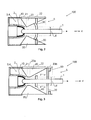
- Fig. 3 shows a cross section through a third embodiment of a circuit breaker 100 according to the invention.
- the third embodiment is very similar to the first and second embodiments described above, with the exception that it additionally to the sealing wall 30 comprises a baffle 40 fixed on the first arcing contact 1.
- the nozzle is shaped differently, i.e. it comprises two third sections 23a and 23b with constant inner diameters.
- the sealing wall 30 takes care of the sealing of the pressure chamber 4, while the whole pressure chamber volume including the volumes on both sides of the baffle 40 is or are at overpressure. After a release of the latch 50, the sealing wall 30 is more strongly accelerated due to its larger diameter.
- Fig. 4 shows a cross section through a fourth embodiment of a circuit breaker 100 according to the invention comprising a two-part pressure chamber 4, which is in part arranged around the arcing chamber 3.
- the fourth embodiment further comprises a damper 60, which is a part of a contact closer 70. Otherwise, the fourth embodiment is very similar to the first to third embodiments.
- the additional part of the pressure chamber 4, which is arranged around the arcing chamber 3, provides additional initial acceleration to the sealing wall 30.
- the additional part of the pressure chamber 4 can be separated or connected to the original pressure chamber 4, i.e. the inner part of the pressure chamber 4, which is congruent with the arcing chamber 3.
- connection holes 98 are connected to the inner part of the pressure chamber 4 through connection holes 98, as shown in Fig. 4 . Due to the larger contact area of the pressurized arc extinguishing fluid 10 with the sealing wall 30, the initial acceleration of the sealing wall or outer plate 30 is increased. This leads to reduced contact separation and arc extinguishing times.
- nominal contacts can be implemented by using the sealing wall 30 as nominal contact in its closed or first position.
- the sealing wall 30 can be part of a nominal contact system of the circuit breaker 100.
- the damper 60 comprises e.g. a set of springs (mechanical, pneumatic, etc.) that are compressed and latched after compression. These springs also act as an energy storage unit 71 for the contact closer 70.
- the secondary latches (not shown) can be part of the contact closer 70, and they can be released to reclose the nominal and arcing contacts 1, 2 of the circuit breaker 100. The energy required during the CLOSE operation is harnessed from the kinetic energy produced during the OPEN operation as described above.
- the CLOSE operation has to counteract mainly the plug-tulip contact force (on the order of O(100) N) and the friction force between the nominal contacts (not shown).
- the latch 50 is energized again and the pressure chamber 4 is then refilled with pressurized arc extinguishing fluid 10 to be ready for the next OPEN operation.
- An OPEN - CLOSE - OPEN (O-C-O) operation is also possible, when the pressure chamber 4 is rapidly refilled with arc extinguishing fluid 10 at the necessary overpressure. Because a volume of the order of 1 liter, i.e. O(1) liters, is sufficient, a fast pressure charging of the pressure chamber 4 is achievable, e.g. by means of several filling inlets.
- Fig. 5 shows a cross section through a fifth embodiment of a circuit breaker 100 according to the invention.
- the fifth embodiment comprises a nozzle 20 with sections 21 and 22 with nonlinearly converging and nonlinearly diverging inner diameters d.
- the nozzle 20 has a nonlinearly converging first section 21 (i.e. with decreasing diameter when moving through the nozzle 20 from left to right or along a preferred gas blowing direction) and a nonlinearly diverging second section 22 (i.e. with increasing diameter when moving through the nozzle 20 from left to right or along a preferred gas blowing direction).
- the nozzle sections may also be nonlinearly converging and linearly diverging, or vice versa linearly converging and nonlinearly diverging.
- the first and second arcing contacts are swapped, i.e. the first arcing contact 1 is movable along the -z direction and structured as tulip, while the second (fixed) arcing contact 2 is structured as plug.
- an additional sealing tube 31 is arranged in the arcing or pressure chamber 3, 4 and moves along -z together with the first arcing contact 1 and the sealing wall 30.
- Fig. 6 shows a schematic representation of a DC medium- or high-voltage power transmission or distribution network comprising a circuit breaker 100 according to the invention.
- the circuit breaker 100 is used to open and/or to close an electrical connection between a first bus bar 201 and a second bus bar 202. Contact separation and arc extinguishing is achieved within less than 10 ms.
- a resonant circuit (203) can be arranged in parallel to the circuit breaker 100 for creating an artificially induced current zero via a passive and/or active resonance scheme during which the arc is extinguished.
- the invention relates to a method for interrupting or establishing an electrical connection in a medium- or high-voltage power transmission or distribution network 200, in particular in a medium- or high-voltage DC power transmission and distribution network, by means of a circuit breaker 100 as disclosed herein.
- the method for interrupting the electrical connection in the medium- or high-voltage DC power transmission network 200 comprises steps of
- the exhaust gap 99 forms a throat of the pressure chamber 4 during a first period, and wherein a nozzle throat forms a throat of the pressure chamber 4 during a second period, in particular wherein the arc 11 is purged during the second period.
- the method does not comprise a step of opening a valve between the pressure chamber 4 and the arcing chamber 3.
- fluid relates to "a substance, such as a liquid [and/] or gas, that can flow, has no fixed shape, and offers little resistance to an external stress" (from http://www.thefreedictionary.com/fluid, accessed on 9/11/2011).
- medium-voltage relates to AC or DC voltages larger than or equal to 1 kV.
- high-voltage relates to AC or DC voltages larger than or equal to 72 kV.
- Typical tripping currents are on the order of 10 kA, i.e. O(10 1 ) kA, or more.
- arcing chamber relates throughout this application to the volume of the circuit breaker where an electrical arc is formed between the first and the second arcing contacts 1, 2 during a separation of the arcing contacts 1, 2.
- throat relates throughout this application, to the smallest opening of the pressure chamber 4 in a down-pressure direction.
- Down-pressure direction means the direction of diminishing pressure.
- tapping shall be understood broadly to also encompass actuating or starting moving or moving the electrical contacts.
Abstract


Description
- The present invention relates to a circuit breaker for a medium or high-voltage electrical circuit. Furthermore, the invention relates to a method for circuit interruption by means of such a circuit breaker and the use of such a circuit breaker in a medium or high-voltage power transmission or distribution network. Also, the invention relates to a power transmission or distribution network comprising such a circuit breaker.
- Prior art circuit breakers can comprise compressed fluids (i.e. gases and/or liquids) as energy reservoirs and piston mechanisms as actuators. In these devices, the stored drive energy is in general used for both mechanical actuation (e.g. separation) of electrical contacts and for pressure build-up in an arc extinguishing fluid. During contact actuation, nominal contacts (i.e. medium or high-voltage contacts that are used during normal, i.e., non-tripping operation) and/or arcing contacts (i.e. medium or high-voltage contacts that are used during tripping of the circuit) in an arcing chamber are mechanically separated to prevent further current flow in the circuit. However, due to voltages above 1 kV, a plasma arc is formed between the already separated arcing contacts. During arc extinguishing, this plasma arc between the arcing contacts is purged by a flow of arc extinguishing fluid during a natural induced zero crossing of the current (i.e. in an AC network) or during an artificially induced zero crossing of the current (i.e. in a DC network) through the arcing contacts. For this, high blowing pressures are necessary in the arc extinguishing fluid. If the arc extinguishing fluid is not pre-pressurized, e.g. by a compressor, the necessary build-up of pressure in the arc extinguishing fluid normally takes place by means of a compression of a gaseous volume of the arc extinguishing fluid (so-called "puffer" technology) in a way similar to handheld pumps for bicycles. In other implementations, the circuit breaker is designed such that additional pressure can be generated in the arc extinguishing fluid during the high current arcing phase. This extra pressure is then used for arc interruption at current zero (so-called "self-blast" technology).
-
US 5,187,339 discloses a high-voltage circuit breaker comprising a first compartment with pressurized SF6 as arc extinguishing fluid. The high-voltage arcing contacts are arranged inside this first compartment. A second, normally unpressurized compartment is located at a distance to the first compartment and comprises a pneumatic jack which is mechanically connected to the arcing contacts. For circuit tripping, valves separating the first compartment from the pneumatic jack are opened and the pneumatic jack is actuated by the pressurized gas contained in the first compartment. Thus, the arcing contacts can be separated. -
US 3,379,849 discloses a high-voltage circuit breaker with pressurized reservoirs containing the arc extinguishing fluid SF6. Valves are opened for a tripping of the circuit and the arc extinguishing fluid is on the one hand used to actuate a piston mechanism which separates the arcing contacts and on the other hand it is used for arc extinguishing in the arcing chamber, which is located at a distance to the piston mechanism. -
US 7,528,332 discloses an actuating device and a circuit breaker device that rely on an electrical discharge in a gas volume. The electrical discharge is used to rapidly heat the gas and thus increase its pressure. A connected piston mechanism converts the resulting pressure build-up in the gas into a mechanical movement which can be used to mechanically actuate electrical contacts. - The disclosed devices and/or methods have the disadvantage, however, that their setup is rather complicated and/or that they exhibit rather slow mechanical contact actuating and/or arc extinguishing performances.
- Hence it is a general objective of the present invention to provide an improved circuit breaker that at least partially overcomes these disadvantages. It is a further objective of the invention to provide a method for interrupting an electrical circuit by means of such a circuit breaker. Yet another objective of the invention is to provide a use of such a circuit breaker for tripping an electrical connection. Yet a further objective of the invention is to provide a high-voltage power transmission or distribution network comprising such a circuit breaker.
- These objectives are achieved by the device and methods of the independent claims.
- Accordingly, a circuit breaker for tripping an electrical connection in a medium- or high-voltage power transmission network comprises at least a first arcing contact and a second arcing contact. These arcing contacts are structured to be separated from each other for tripping the medium or high-voltage electrical connection. The arcing contacts are arranged in an arcing chamber of the circuit breaker and at least the first arcing contact is movable with respect to the second arcing contact from a first position to a second position. The electrical connection between the arcing contacts is closed, i.e. connected, in the first position and open, i.e. disconnected, in the second position. Thus, the electrical connection is trippable or disconnectable by moving at least the first arcing contact of the circuit breaker from the first position to the second position. As an option, a movement of both arcing contacts is possible, as well. Furthermore, the circuit breaker comprises an arc extinguishing fluid for extinguishing an arc that is formed between the first and the second arcing contact during tripping of the electrical connection (see below). This arc is formed due to the voltages above e.g. 1 kV during or after the arcing contacts are mechanically separated. The arc extinguishing fluid is also used for moving the first arcing contact from the first (closed) position to the second (open) position. In other words, the pressurized arc extinguishing fluid acts as an energy reservoir for actuating the movement of the first arcing contact with respect to the second arcing contact. Furthermore, the circuit breaker comprises at least one nozzle which is arranged in the arcing chamber. The nozzle is adapted - when the electrical connection is tripped or, in other words, the arcing contacts are separated - to direct a flow of the pressurized arc extinguishing fluid towards the arc for extinguishing the arc. In other words, the arc is purged by the arc extinguishing fluid during a natural or artificially induced current zero. Such an artificially induced current zero can advantageously be produced by a commutation or resonant circuit in a DC network via a passive and/or active resonance scheme.
- Furthermore, the circuit breaker comprises a pressure chamber and an expansion chamber. The arc extinguishing fluid is - at least when the circuit breaker is closed or, in other words, when the first arcing contact is in its first position - arranged in the pressure chamber at an overpressure (of advantageously at least 7 bar, more preferably at least 30 bar, even more preferably at least 60 bar) compared to the pressure in the expansion chamber.
- In embodiments, the arc extinguishing fluid is arranged in the pressure chamber at the overpressure compared to the expansion chamber at least when the first arcing contact is in the first position (i.e. when the electrical circuit is closed), and/or
- at least before a separation operation of the arcing contacts is initiated and/or before a tripping command, e.g. from a bay controller, is issued to and/or is received by the circuit breaker. Thus, almost all (in terms of Mols) of the arc extinguishing fluid can be kept in the pressure chamber during normal (i.e. non-tripping) operation conditions.
- In embodiments, the pressure chamber and the arcing chamber are not separated by a valve, or, in other words, no valve and/or no fluid conduction means such as tubings is or are arranged between the arcing chamber and the pressure chamber. This has the advantage that the design of the circuit breaker is simplified.
- Furthermore, the circuit breaker comprises at least one movable sealing wall which is mechanically interconnected to the first arcing contact. The sealing wall is structured to transfer a movement of the sealing wall to the first arcing contact. At least a part of the pressure chamber is formed by the sealing wall at least when the first arcing contact is in its first position. In other words, for tripping the electrical connection, the sealing wall acts as a piston that is moved by the pressurized arc extinguishing fluid and this movement is transferred to the first arcing contact which is brought from its first to its second position. The arc between the first and second arcing contacts is concurrently purged by the flowing arc extinguishing fluid. As a result, the energy which is stored in the pressurized arc extinguishing fluid is used
- a) for mechanically moving the first arcing contact and
- b) for creating a flow in the arc extinguishing fluid which is used to purge the arc.
- By using the pressurized arc extinguishing fluid both for contact separation and for arc extinguishing, it is an advantage, that the setup of the circuit breaker is simplified and shorter tripping and arc extinguishing times are achieved.
- In an embodiment, at least a part of the pressure chamber is formed by the arcing chamber. For example, the pressure chamber and the arcing chamber are the same chambers. Thus, the setup of the circuit breaker is further simplified, because no separate pressure and arcing chambers are necessary. This helps to decrease complexity of the setup and to further reduce tripping and arc extinguishing times.
- In another embodiment, at least one of the arcing contacts - preferably both of the arcing contacts - is or are arranged in the pressure chamber. This has the advantage that the circuit breaker setup is simplified.
- Advantageously, the nozzle comprises a first section with a linearly or nonlinearly converging inner diameter and a second section with a linearly or nonlinearly diverging inner diameter. Preferably, the nozzle additionally comprises at least one third section with a constant inner diameter. The term "inner diameter" relates to a lateral diameter of an inner volume of the nozzle which encloses the arc extinguishing fluid. The sections can be arranged such that between the first and the second section the inner diameter of the nozzle has a minimum. In one embodiment, the third section with the constant diameter shall form the minimum inner diameter of the nozzle and shall thus form the nozzle throat. In other words, a lateral cross section of the nozzle profile can show a convex shape (see e.g. in the Figures). Then, when the arc is formed near that region with the minimum inner diameter of the nozzle, the flow of the arc extinguishing fluid through the nozzle can more easily be directed towards the arc and the arc can more effectively be purged by the flow of arc extinguishing fluid through the nozzle.
- In another advantageous embodiment, the first and second arcing contacts are arranged in a coaxial configuration. In other words, axes of the arcing contacts, e.g. symmetry axes, are congruent. More advantageously, a contact separation movement direction is also congruent with these symmetry axes. Even more advantageously, the arcing contacts are arranged in a tulip-plug-configuration or in a head-to-head-configuration. In a tulip-plug-configuration, one arcing contact comprises a convex section or protrusion which is adapted to be insertable into a concave section or recess of the other arcing contact. In a head-to-head-configuration, convex or flat head sections of the respective arcing contacts are adapted to touch each other. Thus, a more reliable electrical connection is achieved when the arcing contacts are closed while a separation of the arcing contacts is not impeded.
- Advantageously, the sealing wall can be structured to exhibit different shapes. As examples, the sealing wall can be flat, curved, or calotte-shaped. Thus, an interaction of the pressurized arc extinguishing fluid with the sealing wall that acts as a piston during a tripping of the electrical circuit can be optimized to achieve shorter arcing contact separation times.
- In another advantageous embodiment, the circuit breaker can - additionally to the sealing wall - comprise at least one movable baffle that can, e.g., act as "assistant piston" in addition to the sealing wall. The baffle is mechanically interconnected to the first arcing contact, and a movement of the baffle is transferred to the first arcing contact similarly as for the sealing wall. In other words, for tripping the electrical connection, the baffle additionally to the sealing wall can act as a piston that is moved by the pressurized arc extinguishing fluid, and this movement is transferred to the first arcing contact which is brought from its first to its second position. This has the advantage that an interaction of the pressurized arc extinguishing fluid with the baffle and sealing wall during a tripping of the electrical circuit can be optimized to achieve shorter arcing contact separation times. Furthermore, an arc extinguishing fluid flow condition which is suitable for efficient arc extinguishing can more easily be shaped using the additional baffle (see below).
- Advantageously, a latch is arranged in the circuit breaker for inhibiting a movement of the first arcing contact from the first position to the second position. In other words, during normal operation (when the electrical connection is kept closed), the overpressure of the arc extinguishing fluid in the pressure chamber is kept up. Suitable sealing means, e.g. O-rings, can be arranged, e.g., on the sealing wall and/or on non-moving parts for this purpose. Then, for tripping the electrical connection, the latch is opened and the pressurized arc extinguishing fluid moves the sealing wall and thus mechanically separates the arcing contacts by moving the first arcing contact from its first position to its second position.
- Advantageously, the circuit breaker comprises a contact closer which moves the first arcing contact from its second position back to its first position. In other words, the contact closer is used - e.g. after a tripping of the electrical connection - to reclose the arcing contact. Thus, normal operation conditions can be restored. More preferably, the contact closer comprises an energy storage unit which is adapted to store at least a part of the kinetic energy of a movement of said first arcing contact from said first position to said second position. Thus, energy is saved.
- In another advantageous embodiment, the circuit breaker is adapted to move the first arcing contact from its first position to its second position and to extinguish the arc between the arcing contacts within 20 ms, preferably within 10 ms, more preferably within 5 ms. Thus, swifter reaction times are achieved and damage to electrical equipment, e.g. in a failure situation, is more reliably avoided or reduced.
- As another aspect of the invention, a use of a circuit breaker as described above is disclosed for tripping an electrical connection in a medium or high-voltage power transmission or distribution network, in particular in a medium or high-voltage DC power transmission or distribution network.
- In such a DC network, upon occurrence of a fault, the circuit breaker (i.e. circuit breaker with DC interruption capability) is tripped, an artificially induced current zero is induced, e.g. by using a commutation circuit or a resonant circuit for, in particular over, the circuit breaker, and subsequently the current is interrupted at this current zero. Thus, the circuit breaker can, for example, achieve DC interruption capability by its very fast interruption times (e.g. achieved according to the present invention) and/or by a commutation or resonant circuit being arranged in the network (e.g. being arranged in parallel and/or in series to the circuit breaker).
- As yet another aspect of the invention, a method for interrupting, e.g. tripping, or establishing, i.e. closing, an electrical connection in a medium or high-voltage power transmission or distribution network by means of a circuit breaker as described above is disclosed. Thus, e.g. in a fault situation, the electrical connection can more swiftly be tripped and damage in the power transmission or distribution can be avoided or reduced.
- The invention and its embodiments will more fully be appreciated by reference to the following detailed description of presently preferred but nonetheless illustrative embodiments in accordance with the present invention when taken in conjunction with the accompanying drawings.
-
Fig. 1a shows a cross section through a first embodiment of a circuit breaker according to the invention with a first arcing contact in a first position; -
Fig. 1b shows a cross section through the first embodiment of the circuit breaker fromFig. 1a in a phase when an arc starts to build up between the first arcing contact and a second contact; -
Fig. 1c shows a cross section through the first embodiment of the circuit breaker fromFigs. 1a and 1b in a phase when the arc is about to be purged by a flow of arc extinguishing fluid; -
Fig. 2 shows a cross section through a second embodiment of a circuit breaker according to the invention comprising a curved sealing wall; -
Fig. 3 shows a cross section through a third embodiment of a circuit breaker according to the invention comprising a baffle; -
Fig. 4 shows a cross section through a fourth embodiment of a circuit breaker according to the invention comprising a pressure chamber which is partly arranged around an arcing chamber and further comprising a damper and a contact closer; -
Fig. 5 shows a cross section through a fifth embodiment of a circuit breaker according to the invention comprising a nozzle with a nonlinearly converging and a nonlinearly diverging inner diameter and further comprising a sealing tube; and -
Fig. 6 shows a schematic representation of a DC medium- or high-voltage power transmission network comprising a circuit breaker according to the invention. -
Fig. 1a shows a cross section through a first embodiment of acircuit breaker 100 in a closed position. Thecircuit breaker 100 comprises thefirst arcing contact 1 and asecond arcing contact 2 which are arranged coaxially (about symmetry axis z) in a tulip-plug configuration. Thefirst arcing contact 1 is in a first position, i.e. is electrically connected to thesecond arcing contact 2. An arc extinguishing fluid (e.g. technical air) 10 is arranged at an overpressure of 60 bar (compared to an absolute pressure of a few bar, i.e. below 10 bar in an expansion chamber 5) inside a pressure chamber 4 (with its volume being for example 3 liters) which is congruent with an arcing chamber 3 of thecircuit breaker 100. The term "arcing chamber" relates to the volume of the circuit breaker where an electrical arc is formed between the first and thesecond arcing contacts contacts wall 30 which provides a fluid-tight seal. The sealingwall 30 is mechanically fixed to thefirst arcing contact 1, which is structured to be movable along the +z direction. Due to the overpressure of thearc extinguishing fluid 10 in the pressure chamber 4 compared to theexpansion chamber 5, an initial force F with direction +z is exerted onto the sealingwall 30 and thefirst arcing contact 1. This initial force F is given by F = p·A, with A being the area of the sealingwall 30 which is in contact with thearc extinguishing fluid 10 and p being the overpressure of thearc extinguishing fluid 10. Initial pushing forces on the order of O(101) kN are typically obtained. The initial pushing force F is counteracted by a holding force F' along -z from alatch 50, which holds the sealingwall 30 in position, thus seals the pressure chamber 4, and keeps up the overpressure of thearc extinguishing fluid 10 in the pressure chamber 4. - For clarity, the initial pushing force F is counteracted by a holding force F' along -z from a
latch 50, before a separation operation of the arcingcontacts circuit breaker 100, wherein thelatch 50 holds the sealingwall 30 in position, thus seals the pressure chamber 4, and keeps up the overpressure of thearc extinguishing fluid 10 in the pressure chamber 4. - Furthermore, the circuit breaker comprises a
nozzle 20 with afirst section 21 and asecond section 22. In thefirst section 21, thenozzle 20 exhibits a linearly converging inner diameter d along +z (i.e. the nozzle's lateral opening diameter decreases along +z) whereas in thesecond section 22, thenozzle 20 exhibits a linearly diverging inner diameter d. In other words, the inner diameter d of thenozzle 20 has a minimum (so-called "nozzle throat") between thefirst section 21 and thesecond section 22. A contact position of the first andsecond arcing contacts - For clarity, the axial contact position (i.e. axial position of contacting or touching) of the first and
second arcing contacts -
Fig. 1b shows a cross section through the first embodiment of the circuit breaker fromFig. 1a in a partly opened position. Here, a tripping command has been issued to the circuit breaker, which leads to an opening or releasing of thelatch 50, e.g. by an electromagnetic coil in thelatch 50. Then, the initial force F (see above) pushes the sealingwall 30 and thefirst arcing contact 1 along the +z direction. In other words, the sealingwall 30 acts as a piston in this case. The relatively high initial force F leads to high accelerations of the moving parts, i.e. of the sealingwall 30 and thefirst arcing contact 1. Typical movable masses are in the range of few kg, and preferably below 10 kg, in this embodiment, typical initial accelerations are in the range of several km/s2, i.e. preferably larger than 1 km/s2. Due to the movement of the sealingwall 30 along the +z direction, the arcingcontacts arc 11 starts to build up between the first andsecond arcing contact annular exhaust gap 99 is created between the divergingsection 22 of thenozzle 20 and the sealingwall 30, that leads to fluid flow (black arrows) and drop of overpressure in the pressure chamber 4. In this phase (which may be called first phase), the design of thenozzle 20 and the sealingwall 30 ensures that this gap is the "throat" of the pressure chamber 4 for several centimeters, e.g. 10 cm, of travel along +z of the sealingwall 30 and thefirst arcing contact 1. The term "throat" relates to the smallest opening of the pressure chamber 4 in a down-pressure direction. In other words, this means that up-stream of the throat there is a subsonic (and thus still high pressure) arc extinguishing fluid flow regime that continues to apply a large force F>F" and pushes the sealingwall 30 and thefirst arcing contact 1 further along the +z direction. In this phase, contact separation occurs and thearc 11 is "drawn" between thefirst arcing contact 1 and thesecond arcing contact 2; then thearc 11 burns in the high pressure subsonic flow regime of thearc extinguishing fluid 10. -
Fig. 1c shows a cross section through the first embodiment of thecircuit breaker 100 fromFigs. 1a and 1b in a further opened position. Here, thefirst arcing contact 1 is almost in a fully opened second position, i.e. it is mechanically disconnected from thesecond arcing contact 2 but still electrically connected through the burningarc 11. In this phase, thisarc 11 is about to be purged by the flow of thearc extinguishing fluid 10 during a natural (for AC currents) or artificially induced (for DC currents) current zero through thearc 11. In this phase (which may be called second phase), the annular exhaust area defined by the gap between the sealingwall 30 and the divergingsection 22 of thenozzle 20 becomes bigger than the nozzle throat area (i.e. the nozzle throat becomes the throat of the pressure chamber 4). Then, the Mach = 1 plane is established at the nozzle throat and thus the necessary flow conditions for arc extinguishing are established at the nozzle throat (i.e. the Mach = 1 plane is established in the flow of the arc extinguishing fluid). These flow conditions lead to successful arc interruption in thecircuit breaker 100. - To summarize, the
circuit breaker 100 is capable of performing a faster contact separation and arc extinguishing because it is actuated by self-stored pressurizedarc extinguishing fluid 10. The term "self-stored" relates to the fact that the storage volume for the pressurized arc extinguishing fluid 10 (i.e. the pressure chamber 4) is actually at least in part made up by the arcing chamber 3 itself. Therefore, no tubings or similar fluid conduction means need to be used. In the first position, the pressure chamber 4 is closed by the sealingwall 30, which is fixed to the movablefirst arcing contact 1. The sealingwall 30 acts as a valve and as a piston, because it opens the outflow of the pressurizedarc extinguishing fluid 10 and it concurrently actuates the contact separation. Proper design and dimensioning of the circuit breaker enables the stored pressurizedarc extinguishing fluid 10 to perform very fast contact displacement (in a few ms, i.e. below 10 ms) and to perform blowing of thegaseous arc 11 for arc extinction on the same timescale. -
Fig. 2 shows a cross section through a second embodiment of acircuit breaker 100 according to the invention. The second embodiment is very similar to the first embodiment described above, with the exception of a curved (concave-shaped) sealingwall 30 instead of theflat sealing wall 30 from the first embodiment. This leads to a higher mechanical robustness. Other shapes are possible, as well. -
Fig. 3 shows a cross section through a third embodiment of acircuit breaker 100 according to the invention. The third embodiment is very similar to the first and second embodiments described above, with the exception that it additionally to the sealingwall 30 comprises abaffle 40 fixed on thefirst arcing contact 1. Furthermore, the nozzle is shaped differently, i.e. it comprises twothird sections wall 30 takes care of the sealing of the pressure chamber 4, while the whole pressure chamber volume including the volumes on both sides of thebaffle 40 is or are at overpressure. After a release of thelatch 50, the sealingwall 30 is more strongly accelerated due to its larger diameter. After only a few mm of travel along the +z direction, the area between thebaffle 40 and the divergingsection 22 of thenozzle 20 becomes the throat (after the sealingwall 30 passes an end of thethird section 23b of the nozzle 20). This results in a lower pressure regime between thebaffle 40 and the sealingwall 30 compared to the arcing chamber 3. In this phase, things are brought back to the scenario described above inFig. 1b with regard to the first embodiment. Advantages of this design are: - first, a sealing of the pressure chamber 4 can be implemented more easily in the contact surface between the
third section 23b of thenozzle 20 with constant inner diameter d and the sealingwall 30 and - second, the use of the
larger sealing wall 40 results in a higher initial acceleration due to an increased initial force F"'>F (as compared toFig. 1a ). This leads to a reduction of contact separation times and arc extinguishing times. -
Fig. 4 shows a cross section through a fourth embodiment of acircuit breaker 100 according to the invention comprising a two-part pressure chamber 4, which is in part arranged around the arcing chamber 3. The fourth embodiment further comprises adamper 60, which is a part of a contact closer 70. Otherwise, the fourth embodiment is very similar to the first to third embodiments. The additional part of the pressure chamber 4, which is arranged around the arcing chamber 3, provides additional initial acceleration to the sealingwall 30. The additional part of the pressure chamber 4 can be separated or connected to the original pressure chamber 4, i.e. the inner part of the pressure chamber 4, which is congruent with the arcing chamber 3. Here, the outer part of the pressure chamber 4 is connected to the inner part of the pressure chamber 4 through connection holes 98, as shown inFig. 4 . Due to the larger contact area of the pressurizedarc extinguishing fluid 10 with the sealingwall 30, the initial acceleration of the sealing wall orouter plate 30 is increased. This leads to reduced contact separation and arc extinguishing times. - With proper design, the initial "kick" or acceleration can be sufficient for obtaining the desired contact separation and arc extinguishing performances so that the
baffle 40 can be optional. For example, nominal contacts can be implemented by using the sealingwall 30 as nominal contact in its closed or first position. In other words, the sealingwall 30 can be part of a nominal contact system of thecircuit breaker 100. - At the end of the OPEN operation described above, the deceleration (damping) and stop of the moving first arcing
contact 1, sealingwall 30, and baffle 40 can be achieved by thedamper 60. In this embodiment, thedamper 60 comprises e.g. a set of springs (mechanical, pneumatic, etc.) that are compressed and latched after compression. These springs also act as anenergy storage unit 71 for the contact closer 70. The secondary latches (not shown) can be part of the contact closer 70, and they can be released to reclose the nominal andarcing contacts circuit breaker 100. The energy required during the CLOSE operation is harnessed from the kinetic energy produced during the OPEN operation as described above. The CLOSE operation has to counteract mainly the plug-tulip contact force (on the order of O(100) N) and the friction force between the nominal contacts (not shown). Once the arcingcontacts latch 50 is energized again and the pressure chamber 4 is then refilled with pressurizedarc extinguishing fluid 10 to be ready for the next OPEN operation. An OPEN - CLOSE - OPEN (O-C-O) operation is also possible, when the pressure chamber 4 is rapidly refilled witharc extinguishing fluid 10 at the necessary overpressure. Because a volume of the order of 1 liter, i.e. O(1) liters, is sufficient, a fast pressure charging of the pressure chamber 4 is achievable, e.g. by means of several filling inlets. -
Fig. 5 shows a cross section through a fifth embodiment of acircuit breaker 100 according to the invention. The fifth embodiment comprises anozzle 20 withsections nozzle 20 has a nonlinearly converging first section 21 (i.e. with decreasing diameter when moving through thenozzle 20 from left to right or along a preferred gas blowing direction) and a nonlinearly diverging second section 22 (i.e. with increasing diameter when moving through thenozzle 20 from left to right or along a preferred gas blowing direction). Please note that generally the nozzle sections may also be nonlinearly converging and linearly diverging, or vice versa linearly converging and nonlinearly diverging. Furthermore, the first and second arcing contacts are swapped, i.e. thefirst arcing contact 1 is movable along the -z direction and structured as tulip, while the second (fixed) arcingcontact 2 is structured as plug. As shown inFig. 5 , an additional sealing tube 31 is arranged in the arcing or pressure chamber 3, 4 and moves along -z together with thefirst arcing contact 1 and the sealingwall 30. An advantage of this embodiment is that a larger actuating area can be used on the sealingwall 30 which results in a higher initial force F""'>F (as compared toFig. 1a ). Furthermore, flow perturbations in the nozzle are reduced. -
Fig. 6 shows a schematic representation of a DC medium- or high-voltage power transmission or distribution network comprising acircuit breaker 100 according to the invention. Thecircuit breaker 100 is used to open and/or to close an electrical connection between afirst bus bar 201 and asecond bus bar 202. Contact separation and arc extinguishing is achieved within less than 10 ms. A resonant circuit (203) can be arranged in parallel to thecircuit breaker 100 for creating an artificially induced current zero via a passive and/or active resonance scheme during which the arc is extinguished. - In another aspect the invention relates to a method for interrupting or establishing an electrical connection in a medium- or high-voltage power transmission or
distribution network 200, in particular in a medium- or high-voltage DC power transmission and distribution network, by means of acircuit breaker 100 as disclosed herein. - In embodiments, the method for interrupting the electrical connection in the medium- or high-voltage DC
power transmission network 200 comprises steps of - receiving a tripping command by the
circuit breaker 100, - accelerating the sealing
wall 30 and thefirst arcing contact 1 and mechanically separating the arcingcontacts fluid 10 from the pressure chamber (4), - creating and/or changing an
exhaust gap 99 between thenozzle 20 and the sealingwall 30 or between thenozzle 20 and a baffle 40 (if present), and - purging the
arc 11 by a flow of the arc-extinguishingfluid 10 through thenozzle 20. - In embodiments, the
exhaust gap 99 forms a throat of the pressure chamber 4 during a first period, and wherein a nozzle throat forms a throat of the pressure chamber 4 during a second period, in particular wherein thearc 11 is purged during the second period. - In embodiments, the method further comprises a step of establishing a Mach = 1 plane in the flow of the arc-extinguishing
fluid 10 at thenozzle 20, and/or - the method does not comprise a step of opening a valve between the pressure chamber 4 and the arcing chamber 3.
- The term "fluid" relates to "a substance, such as a liquid [and/] or gas, that can flow, has no fixed shape, and offers little resistance to an external stress" (from http://www.thefreedictionary.com/fluid, accessed on 9/11/2011).
- The term "medium-voltage" relates to AC or DC voltages larger than or equal to 1 kV.
- The term "high-voltage" relates to AC or DC voltages larger than or equal to 72 kV.
- Typical tripping currents are on the order of 10 kA, i.e. O(101) kA, or more.
- While there are shown and described presently preferred embodiments of the invention, it is to be distinctly understood that the invention is not limited thereto but may otherwise variously be embodied and practiced within the scope of the following claims.
- The term "arcing chamber" relates throughout this application to the volume of the circuit breaker where an electrical arc is formed between the first and the
second arcing contacts contacts - The term "throat" relates throughout this application, to the smallest opening of the pressure chamber 4 in a down-pressure direction. Down-pressure direction means the direction of diminishing pressure.
- The term "tripping" shall be understood broadly to also encompass actuating or starting moving or moving the electrical contacts.
-
Reference numbers 1, 2 arcing contacts 3 arcing chamber 4 pressure chamber 5 expansion chamber 10 arc extinguishing fluid 11 arc 20 nozzle 21, 22 first and second sections of nozzle 2023a, 23b third sections of nozzle 20 d inner diameter of nozzle 2030 sealing wall, outer plate 31 sealing tube 40 baffle 50 latch 60 damper 70 contact closer 71 energy storage unit of contact closer 70 98 connection holes 99 exhaust gap, annular exhaust gap 100 circuit breaker 200 power transmission or distribution network 201, 202 bus bars 203 commutation circuit, resonant circuit.
Claims (21)
- A medium- or high-voltage circuit breaker (100) comprising- at least a first arcing contact (1) and a second arcing contact (2), wherein said arcing contacts (1,2) are arranged in an arcing chamber (3) and wherein at least said first arcing contact (1) is movable with respect to said second arcing contact (2) from a first position to a second position, wherein an electrical connection between said arcing contacts (1,2) is closed in said first position and open in said second position,- an arc extinguishing fluid (10) for extinguishing an arc (11) between said first arcing contact (1) and said second arcing contact (2) and for moving said first arcing contact (1) from said first position to said second position,- at least one nozzle (20) arranged in said arcing chamber (3) and adapted to direct a flow of said arc extinguishing fluid (10) towards said arc (11) for extinguishing said arc (11),- a pressure chamber (4) and an expansion chamber (5), wherein said arc extinguishing fluid (10) is arranged in said pressure chamber (4) at an overpressure to said expansion chamber (5) at least when said first arcing contact (1) is in said first position,- at least one movable sealing wall (30) mechanically interconnected to said first arcing contact (1), wherein said mechanical interconnection is adapted to transfer a movement of said sealing wall (30) to said first arcing contact (1),
characterized in that at least a part of said pressure chamber (4) is formed by said sealing wall (30) at least when said first arcing contact (1) is in said first position. - The circuit breaker (100) of claim 1, wherein at least a part of said pressure chamber (4) is formed by said arcing chamber (3).
- The circuit breaker (100) of claim 2, wherein said pressure chamber (4) and said arcing chamber (3) are the same chamber (3, 4).
- The circuit breaker (100) of any of the preceding claims 1-2, wherein at least a part of said pressure chamber (4) is arranged around said arcing chamber (3).
- The circuit breaker (100) of any of the preceding claims, wherein said arcing contacts (1,2) are arranged in said pressure chamber (4).
- The circuit breaker (100) of any of the preceding claims, wherein said nozzle (20) comprises a first section (21) with a linearly or nonlinearly converging inner diameter (d) and a second section (22) with a linearly or nonlinearly diverging inner diameter (d), in particular wherein said nozzle (20) additionally comprises at least one third section (23a, 23b) with a constant inner diameter (d).
- The circuit breaker (100) of any of the preceding claims, wherein the nozzle (20) has a nozzle throat and a contact position, in particular an axial contact position, of the first and second arcing contacts (1, 2) is arranged near the nozzle throat, in particular within an axial distance to a center of the nozzle throat of less than five times of a or the diameter of the nozzle throat.
- The circuit breaker (100) of any of the preceding claims, wherein said overpressure of said arc extinguishing fluid (10) in said pressure chamber (4) is at least 7 bar, preferably at least 30 bar, more preferably at least 60 bar.
- The circuit breaker (100) of any of the preceding claims, wherein said arcing contacts (1,2) are arranged in a coaxial configuration, in particular wherein said arcing contacts (1,2) are arranged in a tulip-plug-configuration or in a head-to-head-configuration.
- The circuit breaker (100) of any of the preceding claims, wherein said sealing wall (30) is flat or is curved or is calotte-shaped, and/or wherein said sealing wall (30) is part of a nominal contact system of the circuit breaker (100).
- The circuit breaker (100) of any of the preceding claims, further comprising at least one movable baffle (40) mechanically interconnected to said first arcing contact (1), wherein said mechanical interconnection is adapted to transfer a movement of said baffle (40) to said first arcing contact (1).
- The circuit breaker (100) of any of the preceding claims, further comprising a latch (50) for inhibiting a movement of said first arcing contact (1) from said first position to said second position and for up-keeping said overpressure of said arc extinguishing fluid (10) in said pressure chamber (4).
- The circuit breaker (100) of any of the preceding claims, further comprising:a damper (60) for decelerating and stopping a movement of the first acting contact (1) and the sealing wall (30), and in particular of a baffle (40) according to claim 11; and/or comprisinga contact closer (70) for moving said first arcing contact (1) from said second position to said first position, and in particular wherein said contact closer (70) comprises an energy storage unit (71) which is adapted to store at least a part of the kinetic energy of a movement of said first arcing contact (1) from said first position to said second position.
- The circuit breaker (100) of any of the preceding claims, the circuit breaker (100) being adapted to move said first arcing contact (1) from said first position to said second position and to extinguish said arc (11) between said first arcing contact (1) and said second arcing contact (2) within 20 ms, preferably within 10 ms, more preferably within 5 ms, and/or
the circuit breaker (100) being equipped with a commutation circuit (203) or a resonant circuit (203) for artificially inducing a current zero. - The circuit breaker (100) of any of the preceding claims, wherein no tubings or fluid conduction means are present for the arc-extinguishing fluid (10), and/or
wherein no valve for the arc extinguishing fluid (10) is arranged between the pressure chamber (4) and the arcing chamber (3). - The circuit breaker (100) of any of the preceding claims, wherein the arc-extinguishing fluid (10) is arranged in the pressure chamber (4) at an overpressure to the expansion chamber (5):at least before a separation operation of the arcing contacts (1, 2) is initiated, and/orat least before a tripping command is received by the circuit breaker (100).
- A power transmission or distribution network (200), in particular a medium or high-voltage DC power transmission or distribution network (200), comprising at least one circuit breaker (100) of any of the claims 1 to 16, in particular wherein the DC power transmission or distribution network (200) further comprises a commutation circuit (203) or a resonant circuit (203) for creating an artificially induced current zero for the circuit breaker (100).
- A method for interrupting or establishing an electrical connection in a medium- or high-voltage power transmission or distribution network (200), in particular in a medium- or high-voltage DC power transmission and distribution network, by means of a circuit breaker (100) of any of the preceding claims.
- The method of claim 18 for interrupting the electrical connection in the medium- or high-voltage DC power transmission network (200), comprising steps of- receiving a tripping command by the circuit breaker (100),- accelerating the sealing wall (30) and the first arcing contact (1) and mechanically separating the arcing contacts (1, 2) by the pressurized arc-extinguishing fluid (10) from the pressure chamber (4),- creating and/or changing an exhaust gap (99) between the nozzle (20) and the sealing wall (30) or between the nozzle (20) and a baffle (40), and- purging the arc (11) by a flow of the arc-extinguishing fluid (10) through the nozzle (20).
- The method of any of the claims 18 to 19, wherein the exhaust gap (99) forms a throat of the pressure chamber (4) during a first period, and wherein a nozzle throat forms a throat of the pressure chamber (4) during a second period, and in particular wherein the arc (11) is purged during the second period.
- The method of any of the claims 18 to 20,
the method further comprising a step of establishing a Mach = 1 plane in the flow of the arc-extinguishing fluid (10) at the nozzle (20), and/or
the method not comprising a step of opening a valve between the pressure chamber (4) and the arcing chamber (3).
Priority Applications (1)
| Application Number | Priority Date | Filing Date | Title |
|---|---|---|---|
| EP13161682.3A EP2648202A1 (en) | 2012-04-05 | 2013-03-28 | Circuit breaker |
Applications Claiming Priority (2)
| Application Number | Priority Date | Filing Date | Title |
|---|---|---|---|
| EP12163269 | 2012-04-05 | ||
| EP13161682.3A EP2648202A1 (en) | 2012-04-05 | 2013-03-28 | Circuit breaker |
Publications (1)
| Publication Number | Publication Date |
|---|---|
| EP2648202A1 true EP2648202A1 (en) | 2013-10-09 |
Family
ID=47915139
Family Applications (1)
| Application Number | Title | Priority Date | Filing Date |
|---|---|---|---|
| EP13161682.3A Withdrawn EP2648202A1 (en) | 2012-04-05 | 2013-03-28 | Circuit breaker |
Country Status (3)
| Country | Link |
|---|---|
| US (1) | US20130265693A1 (en) |
| EP (1) | EP2648202A1 (en) |
| CN (1) | CN103367027A (en) |
Families Citing this family (3)
| Publication number | Priority date | Publication date | Assignee | Title |
|---|---|---|---|---|
| CN105680706A (en) * | 2014-11-18 | 2016-06-15 | 台达电子工业股份有限公司 | Direct current power supply apparatus |
| EP3261107A1 (en) * | 2016-06-20 | 2017-12-27 | ABB Schweiz AG | Gas-insulated low- or medium-voltage switch with swirling device |
| EP3503151B1 (en) * | 2017-12-20 | 2022-04-13 | Hitachi Energy Switzerland AG | Circuit breaker and method of performing a current breaking operation |
Citations (5)
| Publication number | Priority date | Publication date | Assignee | Title |
|---|---|---|---|---|
| US3379849A (en) | 1964-12-17 | 1968-04-23 | Westinghouse Electric Corp | Dual-pressure gas-blast circuit breaker with piston means and interrupting unit in closed tank |
| US4553008A (en) * | 1984-06-14 | 1985-11-12 | Cooper Industries, Inc. | Load interrupter |
| US5187339A (en) | 1990-06-26 | 1993-02-16 | Merlin Gerin | Gas insulated high-voltage circuit breaker with pneumatic operating mechanism |
| JP2003022737A (en) * | 2001-07-06 | 2003-01-24 | Mitsubishi Electric Corp | Gas blast circuit breaker |
| US7528332B1 (en) | 2004-11-17 | 2009-05-05 | Utron Inc. | High speed actuating device and circuit breaker |
Family Cites Families (6)
| Publication number | Priority date | Publication date | Assignee | Title |
|---|---|---|---|---|
| US4114003A (en) * | 1974-05-08 | 1978-09-12 | Westinghouse Electric Corp. | Quick-acting movable operating-column tripping device |
| JPH01243328A (en) * | 1988-03-25 | 1989-09-28 | Hitachi Ltd | Buffer-type gas-blasted circuit breaker |
| JPH0495322A (en) * | 1990-08-03 | 1992-03-27 | Hitachi Ltd | Gas blast circuit breaker |
| JP4174094B2 (en) * | 1998-01-29 | 2008-10-29 | 株式会社東芝 | Gas circuit breaker |
| JP2005332745A (en) * | 2004-05-21 | 2005-12-02 | Hitachi Ltd | Gas circuit breaker |
| EP2494571B1 (en) * | 2009-10-27 | 2013-12-11 | ABB Technology AG | An hvdc breaker and control apparatus for controlling an hvdc breaker |
-
2013
- 2013-03-28 EP EP13161682.3A patent/EP2648202A1/en not_active Withdrawn
- 2013-04-05 US US13/857,651 patent/US20130265693A1/en not_active Abandoned
- 2013-04-08 CN CN2013101190973A patent/CN103367027A/en active Pending
Patent Citations (5)
| Publication number | Priority date | Publication date | Assignee | Title |
|---|---|---|---|---|
| US3379849A (en) | 1964-12-17 | 1968-04-23 | Westinghouse Electric Corp | Dual-pressure gas-blast circuit breaker with piston means and interrupting unit in closed tank |
| US4553008A (en) * | 1984-06-14 | 1985-11-12 | Cooper Industries, Inc. | Load interrupter |
| US5187339A (en) | 1990-06-26 | 1993-02-16 | Merlin Gerin | Gas insulated high-voltage circuit breaker with pneumatic operating mechanism |
| JP2003022737A (en) * | 2001-07-06 | 2003-01-24 | Mitsubishi Electric Corp | Gas blast circuit breaker |
| US7528332B1 (en) | 2004-11-17 | 2009-05-05 | Utron Inc. | High speed actuating device and circuit breaker |
Non-Patent Citations (1)
| Title |
|---|
| "a substance, such as a liquid [and/] or gas, that can flow, has no fixed shape, and offers little resistance to an external stress", FLUID, 9 November 2011 (2011-11-09), Retrieved from the Internet <URL:http://www.thefreedictionary.com/fluid> |
Also Published As
| Publication number | Publication date |
|---|---|
| US20130265693A1 (en) | 2013-10-10 |
| CN103367027A (en) | 2013-10-23 |
Similar Documents
| Publication | Publication Date | Title |
|---|---|---|
| JP5516568B2 (en) | Puffer type gas circuit breaker | |
| US9299507B2 (en) | Gas circuit breaker | |
| KR20060063720A (en) | Method for breaking current in puffer-type gas circuit breaker and puffer-type gas circuit breaker using the same | |
| US10964498B2 (en) | Gas-insulated low- or medium-voltage load break switch | |
| JP2008210710A (en) | Gas-blast circuit breaker for power | |
| CN107077988A (en) | High voltage puffer circuit breaker and the breaker unit with this puffer circuit breaker | |
| EP2648202A1 (en) | Circuit breaker | |
| KR101786521B1 (en) | High Voltage Gas Circuit Breaker | |
| KR101550299B1 (en) | Circuit breaker for GIS(Gas Insulated Switchgears) | |
| US10170256B2 (en) | Circuit breaker equipped with an extensible exhaust cover | |
| JP2015056249A (en) | Circuit breaker | |
| US3670126A (en) | Compressed-gas circuit interrupter having a pair of rapid transfer insulating nozzles | |
| CN101901721B (en) | Interruptor chamber, HVDC bypass interrupter and high voltage direct current converting plant comprising such chamber | |
| US11764012B2 (en) | Gas circuit breaker | |
| CN111466006A (en) | Gas-insulated high-or medium-voltage circuit breaker | |
| US11217408B2 (en) | Gas circuit breaker | |
| JP2014002868A (en) | Gas-blast circuit breaker | |
| KR20020015896A (en) | Hybrid-extinction type gas circuit breaker | |
| WO2015129273A1 (en) | Gas circuit breaker | |
| KR20220046124A (en) | Self-blast type gas circuit breaker | |
| JP2017120756A (en) | Switchgear | |
| WO2019092861A1 (en) | Gas circuit breaker | |
| JP2020119766A (en) | Gas circuit breaker | |
| US10262813B2 (en) | Circuit breaker containing a gas escape hood with sealable opening | |
| WO2019092862A1 (en) | Gas circuit breaker |
Legal Events
| Date | Code | Title | Description |
|---|---|---|---|
| PUAI | Public reference made under article 153(3) epc to a published international application that has entered the european phase |
Free format text: ORIGINAL CODE: 0009012 |
|
| AK | Designated contracting states |
Kind code of ref document: A1 Designated state(s): AL AT BE BG CH CY CZ DE DK EE ES FI FR GB GR HR HU IE IS IT LI LT LU LV MC MK MT NL NO PL PT RO RS SE SI SK SM TR |
|
| AX | Request for extension of the european patent |
Extension state: BA ME |
|
| 17P | Request for examination filed |
Effective date: 20140401 |
|
| RBV | Designated contracting states (corrected) |
Designated state(s): AL AT BE BG CH CY CZ DE DK EE ES FI FR GB GR HR HU IE IS IT LI LT LU LV MC MK MT NL NO PL PT RO RS SE SI SK SM TR |
|
| GRAP | Despatch of communication of intention to grant a patent |
Free format text: ORIGINAL CODE: EPIDOSNIGR1 |
|
| RIC1 | Information provided on ipc code assigned before grant |
Ipc: H01H 33/32 20060101AFI20151001BHEP Ipc: H01H 33/50 20060101ALI20151001BHEP Ipc: H01H 33/70 20060101ALI20151001BHEP |
|
| INTG | Intention to grant announced |
Effective date: 20151019 |
|
| STAA | Information on the status of an ep patent application or granted ep patent |
Free format text: STATUS: THE APPLICATION IS DEEMED TO BE WITHDRAWN |
|
| 18D | Application deemed to be withdrawn |
Effective date: 20160301 |