EP2648185A1 - Write yoke with stabilizing layer - Google Patents
Write yoke with stabilizing layer Download PDFInfo
- Publication number
- EP2648185A1 EP2648185A1 EP13161782.1A EP13161782A EP2648185A1 EP 2648185 A1 EP2648185 A1 EP 2648185A1 EP 13161782 A EP13161782 A EP 13161782A EP 2648185 A1 EP2648185 A1 EP 2648185A1
- Authority
- EP
- European Patent Office
- Prior art keywords
- yoke
- stabilizing layer
- sub
- magnetic
- write pole
- Prior art date
- Legal status (The legal status is an assumption and is not a legal conclusion. Google has not performed a legal analysis and makes no representation as to the accuracy of the status listed.)
- Withdrawn
Links
- 230000000087 stabilizing effect Effects 0.000 title claims abstract description 37
- 230000005381 magnetic domain Effects 0.000 claims abstract description 25
- 230000005291 magnetic effect Effects 0.000 claims description 36
- 230000008878 coupling Effects 0.000 claims description 9
- 238000010168 coupling process Methods 0.000 claims description 9
- 238000005859 coupling reaction Methods 0.000 claims description 9
- 238000003475 lamination Methods 0.000 claims description 2
- 230000006641 stabilisation Effects 0.000 description 46
- 238000011105 stabilization Methods 0.000 description 46
- 230000005415 magnetization Effects 0.000 description 18
- 238000013500 data storage Methods 0.000 description 11
- 230000002463 transducing effect Effects 0.000 description 8
- 230000004907 flux Effects 0.000 description 7
- 239000000463 material Substances 0.000 description 7
- 230000005290 antiferromagnetic effect Effects 0.000 description 5
- 230000009977 dual effect Effects 0.000 description 4
- 238000003860 storage Methods 0.000 description 4
- 238000005516 engineering process Methods 0.000 description 3
- 238000004519 manufacturing process Methods 0.000 description 3
- 239000002885 antiferromagnetic material Substances 0.000 description 2
- 230000015572 biosynthetic process Effects 0.000 description 2
- 230000008021 deposition Effects 0.000 description 2
- 238000010410 dusting Methods 0.000 description 2
- 229910003321 CoFe Inorganic materials 0.000 description 1
- 230000005316 antiferromagnetic exchange Effects 0.000 description 1
- 150000001875 compounds Chemical class 0.000 description 1
- 239000004020 conductor Substances 0.000 description 1
- 239000000428 dust Substances 0.000 description 1
- 238000011156 evaluation Methods 0.000 description 1
- 230000002349 favourable effect Effects 0.000 description 1
- 239000000696 magnetic material Substances 0.000 description 1
- 230000014759 maintenance of location Effects 0.000 description 1
- 238000000034 method Methods 0.000 description 1
- 239000007779 soft material Substances 0.000 description 1
- 239000007787 solid Substances 0.000 description 1
Images



Classifications
-
- G—PHYSICS
- G11—INFORMATION STORAGE
- G11B—INFORMATION STORAGE BASED ON RELATIVE MOVEMENT BETWEEN RECORD CARRIER AND TRANSDUCER
- G11B5/00—Recording by magnetisation or demagnetisation of a record carrier; Reproducing by magnetic means; Record carriers therefor
- G11B5/127—Structure or manufacture of heads, e.g. inductive
-
- G—PHYSICS
- G11—INFORMATION STORAGE
- G11B—INFORMATION STORAGE BASED ON RELATIVE MOVEMENT BETWEEN RECORD CARRIER AND TRANSDUCER
- G11B5/00—Recording by magnetisation or demagnetisation of a record carrier; Reproducing by magnetic means; Record carriers therefor
- G11B5/127—Structure or manufacture of heads, e.g. inductive
- G11B5/31—Structure or manufacture of heads, e.g. inductive using thin films
- G11B5/3109—Details
- G11B5/313—Disposition of layers
- G11B5/3133—Disposition of layers including layers not usually being a part of the electromagnetic transducer structure and providing additional features, e.g. for improving heat radiation, reduction of power dissipation, adaptations for measurement or indication of gap depth or other properties of the structure
-
- G—PHYSICS
- G11—INFORMATION STORAGE
- G11B—INFORMATION STORAGE BASED ON RELATIVE MOVEMENT BETWEEN RECORD CARRIER AND TRANSDUCER
- G11B5/00—Recording by magnetisation or demagnetisation of a record carrier; Reproducing by magnetic means; Record carriers therefor
- G11B5/127—Structure or manufacture of heads, e.g. inductive
- G11B5/1278—Structure or manufacture of heads, e.g. inductive specially adapted for magnetisations perpendicular to the surface of the record carrier
Definitions
- Various embodiments of the present disclosure are generally directed to a magnetic data writer that is capable of enhanced data recording through magnetic domain control.
- a data writer may be constructed with a write pole coupled to a yoke.
- the yoke may be configured with a stabilizing layer that stabilizes magnetic domains present in the yoke.
- a data writer comprising a write pole coupled to a yoke, the yoke having a stabilizing layer positioned on the yoke and configured to stabilize magnetic domains present in the yoke.
- the stabilizing layer comprises a permanent magnet.
- the stabilizing layer comprises an antiferromagnet.
- the antiferromagnet comprises a lamination of layers.
- the stabilizing layer has a trapezoidal shape.
- the stabilizing layer and write pole are each coupled to a common surface of the yoke.
- the stabilizing layer is centered about and separated from the write pole.
- the stabilizing layer continuously extends across a rear edge of the yoke, the rear edge distal to the write pole.
- the yoke has a trapezoidal shape.
- the yoke stabilizes magnetic domains by reaching a closure domain.
- a magnetic writing element comprising a write pole coupled to a yoke, the yoke comprising first and second sub-yokes each, a first stabilizing layer positioned on the first sub-yoke and configured to stabilize magnetic domains present in the yoke.
- the first and second sub-yokes have substantially matching thicknesses and shapes that form a yoke stack.
- the second sub-yoke has a second stabilizing layer positioned thereon.
- the second stabilizing layer is vertically aligned with the first stabilizing layer.
- first and second stabilizing layers are positioned on a front edge of the first and second sub-yokes, respectively.
- the first and second sub-yokes are antiferromagnetically coupled.
- an apparatus comprising: a write pole coupled to a yoke; and a means for stabilizing the yoke positioned on the yoke.
- the means for stabilizing the yoke comprises first and second sub-yokes that respectively have first and second stabilizing layers configured to stabilize magnetic domains present in the yoke.
- the second stabilizing layer is positioned on a front edge of the second sub-yoke, proximal the write pole, the first stabilizing layer positioned on a rear edge of the first sub-yoke, distal the write pole.
- a seed layer is disposed between the first and second sub-yokes to promote RKKY coupling.
- EAW erase after write
- a data writer may be constructed with a write pole coupled to a yoke that is configured with a stabilizing layer that stabilizes magnetic domains present in the yoke.
- Magnetic control of large magnetically soft materials becomes challenging due to a host of factors that may include at least, elevated heat and data writing cycles.
- the retention of magnetization in a data writer immediately after data programming can be challenging due at least in part to the large magnetic flux produced by modem writer coils and the high energy configurations of data writing components, such as the write pole and yoke.
- FIG. 1 generally illustrates an example data transducing portion 100 of a data storage device.
- the transducing portion 100 is shown in an environment in which various embodiments of the present technology can be advantageously practiced. It will be understood, however, that the various embodiments of this disclosure are not so limited by such environment and can be implemented in a variety of different data storage devices to control magnetic domains and alleviate inadvertent magnetic flux generation conditions, such as EAW.
- the transducing portion 100 is constructed with an actuating assembly 102 that positions a transducing head 104 over programmed data bits 106 present on a magnetic storage media 108.
- the storage media 108 is attached to a spindle motor 110 that rotates during use to produce an air bearing surface (ABS) 112 on which a slider portion 114 of the actuating assembly 102 flies to position a head gimbal assembly (HGA) 116, which includes the transducing head 104, over a desired portion of the media 108.
- ABS air bearing surface
- HGA head gimbal assembly
- the transducing head 104 can include one or more transducing elements, such as a magnetic writer and magnetically responsive reader, which operate to program and read data from the storage media 108, respectively. In this way, controlled motion of the actuating assembly 102 induces the transducers to align with data tracks (not shown) defined on the storage media surfaces to write, read, and rewrite data.
- transducing elements such as a magnetic writer and magnetically responsive reader
- FIG. 2 displays an isometric view of an example magnetic data writer 120 capable of being used in the transducing head 104 of FIG. 1 .
- the data writer 120 can have one or more magnetically conductive poles that act to pass magnetic flux through an adjacent data storage media in predetermined directions.
- One such pole can be configured like the write pole 122 with a relatively large girth distal an ABS tapering to a reduced width pole tip 124 to focus magnetic flux to a particular region of the adjacent data storage media.
- the write pole 122 can be configured in any number of unlimited sizes, shapes, and orientations to funnel magnetization
- the write pole 122 can be coupled to a yoke 126 that is adapted to provide the write pole 122 with magnetization from a write coil (not shown).
- the yoke 126 as shown, can be constructed to be physically larger than the write pole 122, which can aid in sufficiently supplying magnetic flux to the write pole tip 124.
- a wide yoke 126 can provide ample surface area for magnetic domains to get trapped in metastable states, as generally illustrated by region 128.
- FIGS. 3A and 3B respectively provide top views of a portion of a data writer 130 constructed to stabilize magnetic domains and eliminate metastable states.
- a write pole 132 is connected to a yoke 134 that is configured with a predetermined width 136, as measured parallel to the ABS, that is greater than the width of the write pole 132.
- the yoke 134 may develop a plurality of magnetic domains that can become unstable, especially immediately after a data programming cycle.
- a stabilizing layer 138 can be positioned on the yoke 134 to provide a pinned magnetization 140, as displayed in FIG. 3B , that exchange couple to the yoke 134 material and aid in making a Landau closure domain energetically more favorable.
- the shape, size, position, and material of the stabilization layer 138 can be tuned to provide a predetermined amount of hard magnetization to the yoke 134 to promote magnetic domain closure.
- shape anisotropy by configuring the stabilization layer 138 as a trapezoid, as shown, can be chosen during tuning to be combined with forming the stabilization layer 138 of a permanent magnet to generate a pinned magnetization 140 that can more quickly relax native magnetizations 142 of the yoke 134 after a data bit programming cycle.
- the stabilization layer 138 is tuned to be other shapes, such as a rectangle and rhombus, while antiferromagnetic material is used to form the stabilization layer 138 and exchange couple with the yoke 134. Regardless of the tuned configuration of the stabilization layer 138, the chirality of the closure domains, as shown in FIG. 3B , is set by the pinned magnetization 140 and prevents rogue magnetizations from developing into metastable states.
- FIG. 4 displays an isometric view of an example data write yoke 150 constructed in accordance with various embodiments.
- the yoke 150 has a single continuous body 152 that has first and second stabilization layers 154 and 156 positioned on opposite sides of the body 152. As shown, the first and second stabilization layers 154 and 156 are placed on opposite sides of yoke body 152 with respect to both the vertical axis, Y axis, and the transverse axis, Z axis.
- first and second stabilization layers 154 and 156 may be formed individually or commonly tuned to provide the same or different pinned magnetizations adapted to promote closed magnetic domains. That is, the first stabilization layer 154 can be shaped as a trapezoid, be formed as a permanent magnet, and have a magnetization flowing in a first direction while the second stabilization layer 156 may be a rectangle, be constructed as an antiferromagnet, and have a magnetization flowing in a second direction, different from the first direction. Such configurability allows for the stabilization of magnetic components with a variety of shapes, sizes, and numbers of magnetic domains.
- Fig. 5 provides another example data write yoke 160 that further illustrates the ability to tune first and second stabilization layers 162 and 164 to promote magnetic domain closure.
- the first stabilization layer 162 is formed as a trapezoid and coupled to a top surface of the yoke body 166 while the second stabilization layer 164 is formed as a semi-circle and couple to a bottom surface of the body 166, directly underneath the first stabilization layer 162.
- the stabilization layer 162 and 164 are set to provide pinned magnetizations for the same region of the yoke body 166.
- the pinned magnetizations may combine with opposing magnetization directions to impart greater domain control than a single stabilization layer can provide.
- Various embodiments can manipulate the thickness of the stabilization layers 162 and 164 to tune the strength of the pinned magnetization, but such configuration can be done for individual portions or an entire stabilization layer.
- a core portion 168 of the first stabilization layer 162 can have a greater thickness, as measured along the Y axis, than wing portions 170 of the layer 162.
- FIG. 6 shows an example data writer yoke 180 configured with dual body layers 182 and 184 in accordance with various embodiments.
- Each body layer 182 and 184 can be constructed of a continuous film that may or may not have common material composition and magnetic properties.
- the body layers 182 and 184 are exchange coupled to produce a greater number of magnetic domains 186 than when the yoke body is a single continuous layer.
- the tuned configuration of a stabilization layer 188 may differ from the layers illustrated in FIGS. 3A-5 . That is, the elevated number of magnetic domains localized on opposite sides of the yoke 180 may be taken into consideration when tuning the stabilization layer's thickness, material, shape, and position.
- FIG. 7 provides an isometric view of another data writer yoke 200 that has undergone stabilization layer tuning in accordance with various embodiments.
- the yoke 200 has first and second continuous yoke layers 202 and 204 that respectively have stabilization layers 206 and 208 configured to promote closure domain and more rapidly relax magnetization emission from a connected write pole.
- each yoke layer 202 and 204 has a first common thickness 210 while each stabilization layer 206 and 208 has a second common thickness.
- Control of the magnetic domains of the respective yoke layers 202 and 204 can be achieved by any number of unlimited stabilization layer tuned configurations.
- each stabilization layer 206 and 208 is tuned to be a common shape, size, and antiferromagnetic material. Such configuration can produce antiferromagnetic exchange coupling between the stabilization layers 206 and 208 and the respective yoke layers 202 and 204.
- some embodiments dispose a seed layer, such as Ru and Ta, between the yoke layer and stabilization layer to provide RKKY coupling.
- Other embodiments combine the seed layer with a dusting of conductive material, such as CoFe, to ensure strong antiferromagnetic coupling.
- the common tuned configurations of the stabilization layers 206 and 208 may be chosen due to the presence of dual yoke layers 202 and 204, which correspond with separate Landau closure domains. As such, the stabilization layers 206 and 208 may more harmoniously act in concert to control remnant magnetization in the dual yoke layers 202 and 204 if the stabilization layers 206 and 208 are tuned substantially similarly. However, such tuning is not required and in some embodiments the stabilization layers 206 and 208 have considerably different structural and magnetic configurations.
- FIG. 7 provides an example data writing element fabrication routine 220 performed in accordance with various embodiments to tune a writing yoke to deter metastable magnetic states and promote closure domains.
- the routine 220 begins by determining the configuration of the yoke in step 222.
- the evaluation undertaken in step 222 may result in an unlimited variety of yoke configurations that can relate to any number of characteristics, such as number of yoke layers, material, width, and thickness.
- step 224 then forms the yoke with the predetermined configuration.
- decision 226 determines if antiferromagnetic coupling is to be employed to connect at least one stabilization layer to the yoke. If no antiferromagnetic coupling is to be used, step 228 then chooses the stabilization layer configurations, which has an unlimited number of characteristics to evaluate and determine, such as, but not limited to, number of stabilization layers, layer thickness, material, size, and shape.
- the resultant stabilization design is subsequently implemented in step 230 with the formation of the stabilization layer(s) in accordance with the predetermined design.
- step 232 deposits a seed layer onto the yoke to allow the growth of the stabilization layer(s).
- Step 232 may further dust a conductive compound onto the seed layer to further ensure strong antiferromagnetic coupling, but such additional dusting is not required.
- the deposition of the seed layer advances the routine to the design of the stabilization layer(s) in step 228 and the formation of the design in step 230.
- routine 220 can fabricate a data writing element with predetermined magnetic characteristics conducive to one or more Landau closure domains.
- routine 220 is not limited to the process shown in FIG. 8 as the various decisions and steps can be omitted, changed, and added.
- decision 226 and step 228 can be conducted collectively with step 222 so that the data writing element is fully designed prior to the deposition of any components.
- the configuration and material characteristics of the magnetic data writing element described in the present disclosure allows for enhanced magnetic programming by reducing the risk of unwanted magnetic domain configurations in a write yoke and write pole. Moreover, the ability to tune the various layers of a data writing element allows for quickened magnetic relaxation to closure domain, which can correspond to reduced erasure after writing in high areal density data storage devices.
- the embodiments have been directed to magnetic programming, it will be appreciated that the claimed technology can readily be utilized in any number of other applications, such as data sensing and solid state data storage applications.
Landscapes
- Engineering & Computer Science (AREA)
- Manufacturing & Machinery (AREA)
- Physics & Mathematics (AREA)
- Electromagnetism (AREA)
- Magnetic Heads (AREA)
- Recording Or Reproducing By Magnetic Means (AREA)
- Magnetic Record Carriers (AREA)
- Mram Or Spin Memory Techniques (AREA)
Abstract
Description
- Various embodiments of the present disclosure are generally directed to a magnetic data writer that is capable of enhanced data recording through magnetic domain control.
- In accordance with various embodiments, a data writer may be constructed with a write pole coupled to a yoke. The yoke may be configured with a stabilizing layer that stabilizes magnetic domains present in the yoke.
- According to a first aspect of the invention, there is provided a data writer comprising a write pole coupled to a yoke, the yoke having a stabilizing layer positioned on the yoke and configured to stabilize magnetic domains present in the yoke.
- Preferably, the stabilizing layer comprises a permanent magnet.
- Alternatively, it is preferred that the stabilizing layer comprises an antiferromagnet.
- In this case, it is further preferred that the antiferromagnet comprises a lamination of layers.
- Preferably, the stabilizing layer has a trapezoidal shape.
- Preferably, the stabilizing layer and write pole are each coupled to a common surface of the yoke.
- Preferably, the stabilizing layer is centered about and separated from the write pole.
- Preferably, the stabilizing layer continuously extends across a rear edge of the yoke, the rear edge distal to the write pole.
- Preferably, the yoke has a trapezoidal shape.
- Preferably, the yoke stabilizes magnetic domains by reaching a closure domain.
- According to a second aspect of the present invention, there is provided a magnetic writing element comprising a write pole coupled to a yoke, the yoke comprising first and second sub-yokes each, a first stabilizing layer positioned on the first sub-yoke and configured to stabilize magnetic domains present in the yoke.
- Preferably, the first and second sub-yokes have substantially matching thicknesses and shapes that form a yoke stack.
- Preferably, the second sub-yoke has a second stabilizing layer positioned thereon.
- In this case, it is preferred that the second stabilizing layer is vertically aligned with the first stabilizing layer.
- It is also preferred that the first and second stabilizing layers are positioned on a front edge of the first and second sub-yokes, respectively.
- Preferably, the first and second sub-yokes are antiferromagnetically coupled.
- According to a third aspect of the invention, there is provided an apparatus comprising: a write pole coupled to a yoke; and a means for stabilizing the yoke positioned on the yoke.
- Preferably, the means for stabilizing the yoke comprises first and second sub-yokes that respectively have first and second stabilizing layers configured to stabilize magnetic domains present in the yoke.
- Preferably, the second stabilizing layer is positioned on a front edge of the second sub-yoke, proximal the write pole, the first stabilizing layer positioned on a rear edge of the first sub-yoke, distal the write pole.
- Preferably, a seed layer is disposed between the first and second sub-yokes to promote RKKY coupling.
- Embodiments of the present invention will now be described by way of further example only and with reference to the accompanying drawings, in which:
-
FIG. 1 is a block representation of an example portion of a data storage device. -
FIG. 2 provides an example data writing element capable of being used in the portion of the data storage device displayed inFIG. 1 . -
FIGS. 3A and 3B show top views of an example magnetic writing element. -
FIG. 4 displays an isometric view of an example magnetic writing elements constructed in accordance with various embodiments. -
FIG. 5 is an isometric view of an example magnetic data writer. -
FIG. 6 generally illustrates an isometric view of an example magnetic writing elements constructed in accordance with various embodiments. -
FIG. 7 shows an isometric view of an example magnetic data writer. -
FIG. 8 provides a flowchart of a magnetic writing element fabrication routine conducted in accordance with various embodiments of the present invention. - As industry demand for data storage devices with higher data capacity and data transfer rates increases, the size of data bits and speed of data programming are stretched to magnetic and structural limits. For example, when residual magnetic flux is present after a data bit is programmed, an erase after write (EAW) situation may occur as an unpowered magnetic data writer emits flux that inadvertently affects adjacent data bits. Elevated instances of EAW, especially in reduced form factor data storage devices, can reduce data access reliability and increase data access time. Without structural control of EAW, industry cannot provide data storage devices capable of achieving data access operation in heightened data bit density environments.
- Consequently, a data writer may be constructed with a write pole coupled to a yoke that is configured with a stabilizing layer that stabilizes magnetic domains present in the yoke. Magnetic control of large magnetically soft materials, like those used in data access elements, becomes challenging due to a host of factors that may include at least, elevated heat and data writing cycles. Specifically, the retention of magnetization in a data writer immediately after data programming can be challenging due at least in part to the large magnetic flux produced by modem writer coils and the high energy configurations of data writing components, such as the write pole and yoke.
- Although most data writers will eventually relax to an energy minimized Landau closure domain state, magnetic domains may linger in the data writing components for extended periods, which can generate unwanted metastable magnetic states that can affect data writing speed and reliability. The use of at least one stabilizing layer on data writing components can reduce the risk of unwanted magnetic domain configurations by manipulating the energy landscape through tuned shape anisotropy and magnetic material selection.
-
FIG. 1 generally illustrates an exampledata transducing portion 100 of a data storage device. The transducingportion 100 is shown in an environment in which various embodiments of the present technology can be advantageously practiced. It will be understood, however, that the various embodiments of this disclosure are not so limited by such environment and can be implemented in a variety of different data storage devices to control magnetic domains and alleviate inadvertent magnetic flux generation conditions, such as EAW. - The transducing
portion 100 is constructed with anactuating assembly 102 that positions a transducinghead 104 over programmeddata bits 106 present on amagnetic storage media 108. Thestorage media 108 is attached to aspindle motor 110 that rotates during use to produce an air bearing surface (ABS) 112 on which aslider portion 114 of theactuating assembly 102 flies to position a head gimbal assembly (HGA) 116, which includes the transducinghead 104, over a desired portion of themedia 108. - The transducing
head 104 can include one or more transducing elements, such as a magnetic writer and magnetically responsive reader, which operate to program and read data from thestorage media 108, respectively. In this way, controlled motion of the actuatingassembly 102 induces the transducers to align with data tracks (not shown) defined on the storage media surfaces to write, read, and rewrite data. -
FIG. 2 displays an isometric view of an examplemagnetic data writer 120 capable of being used in the transducinghead 104 ofFIG. 1 . Thedata writer 120 can have one or more magnetically conductive poles that act to pass magnetic flux through an adjacent data storage media in predetermined directions. One such pole can be configured like thewrite pole 122 with a relatively large girth distal an ABS tapering to a reducedwidth pole tip 124 to focus magnetic flux to a particular region of the adjacent data storage media. - While the
write pole 122 can be configured in any number of unlimited sizes, shapes, and orientations to funnel magnetization, thewrite pole 122 can be coupled to ayoke 126 that is adapted to provide thewrite pole 122 with magnetization from a write coil (not shown). Theyoke 126, as shown, can be constructed to be physically larger than thewrite pole 122, which can aid in sufficiently supplying magnetic flux to thewrite pole tip 124. However, awide yoke 126 can provide ample surface area for magnetic domains to get trapped in metastable states, as generally illustrated byregion 128. -
FIGS. 3A and 3B respectively provide top views of a portion of adata writer 130 constructed to stabilize magnetic domains and eliminate metastable states. As shown inFIG. 3A , awrite pole 132 is connected to ayoke 134 that is configured with apredetermined width 136, as measured parallel to the ABS, that is greater than the width of thewrite pole 132. Theyoke 134 may develop a plurality of magnetic domains that can become unstable, especially immediately after a data programming cycle. - To alleviate such instability, a stabilizing
layer 138 can be positioned on theyoke 134 to provide a pinnedmagnetization 140, as displayed inFIG. 3B , that exchange couple to theyoke 134 material and aid in making a Landau closure domain energetically more favorable. The shape, size, position, and material of thestabilization layer 138 can be tuned to provide a predetermined amount of hard magnetization to theyoke 134 to promote magnetic domain closure. The use of shape anisotropy by configuring thestabilization layer 138 as a trapezoid, as shown, can be chosen during tuning to be combined with forming thestabilization layer 138 of a permanent magnet to generate a pinnedmagnetization 140 that can more quickly relaxnative magnetizations 142 of theyoke 134 after a data bit programming cycle. - In some embodiments, the
stabilization layer 138 is tuned to be other shapes, such as a rectangle and rhombus, while antiferromagnetic material is used to form thestabilization layer 138 and exchange couple with theyoke 134. Regardless of the tuned configuration of thestabilization layer 138, the chirality of the closure domains, as shown inFIG. 3B , is set by the pinnedmagnetization 140 and prevents rogue magnetizations from developing into metastable states. -
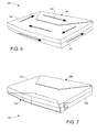
FIG. 4 displays an isometric view of an example data writeyoke 150 constructed in accordance with various embodiments. Theyoke 150 has a singlecontinuous body 152 that has first and second stabilization layers 154 and 156 positioned on opposite sides of thebody 152. As shown, the first and second stabilization layers 154 and 156 are placed on opposite sides ofyoke body 152 with respect to both the vertical axis, Y axis, and the transverse axis, Z axis. - While not required or limited, the first and second stabilization layers 154 and 156 may be formed individually or commonly tuned to provide the same or different pinned magnetizations adapted to promote closed magnetic domains. That is, the
first stabilization layer 154 can be shaped as a trapezoid, be formed as a permanent magnet, and have a magnetization flowing in a first direction while thesecond stabilization layer 156 may be a rectangle, be constructed as an antiferromagnet, and have a magnetization flowing in a second direction, different from the first direction. Such configurability allows for the stabilization of magnetic components with a variety of shapes, sizes, and numbers of magnetic domains. -
Fig. 5 provides another example data write yoke 160 that further illustrates the ability to tune first and second stabilization layers 162 and 164 to promote magnetic domain closure. Thefirst stabilization layer 162 is formed as a trapezoid and coupled to a top surface of theyoke body 166 while thesecond stabilization layer 164 is formed as a semi-circle and couple to a bottom surface of thebody 166, directly underneath thefirst stabilization layer 162. In contrast to the stabilization layers 154 and 156 ofFIG. 4 , thestabilization layer yoke body 166. - With the position of the first and second stabilization layers 162 and 164 on the same portion of the
yoke body 166, the pinned magnetizations may combine with opposing magnetization directions to impart greater domain control than a single stabilization layer can provide. Various embodiments can manipulate the thickness of the stabilization layers 162 and 164 to tune the strength of the pinned magnetization, but such configuration can be done for individual portions or an entire stabilization layer. For example, acore portion 168 of thefirst stabilization layer 162 can have a greater thickness, as measured along the Y axis, thanwing portions 170 of thelayer 162. - Tuning of the yoke 160 is not limited just to the stabilization layers 162 and 164.
FIG. 6 shows an exampledata writer yoke 180 configured with dual body layers 182 and 184 in accordance with various embodiments. Eachbody layer FIG. 6 , the body layers 182 and 184 are exchange coupled to produce a greater number of magnetic domains 186 than when the yoke body is a single continuous layer. - By tuning the
yoke 180 with dual body layers 182 and 184, the tuned configuration of astabilization layer 188 may differ from the layers illustrated inFIGS. 3A-5 . That is, the elevated number of magnetic domains localized on opposite sides of theyoke 180 may be taken into consideration when tuning the stabilization layer's thickness, material, shape, and position. -
FIG. 7 provides an isometric view of anotherdata writer yoke 200 that has undergone stabilization layer tuning in accordance with various embodiments. Theyoke 200 has first and second continuous yoke layers 202 and 204 that respectively havestabilization layers - As shown, each
yoke layer stabilization layer FIG. 7 , eachstabilization layer - The common tuned configurations of the stabilization layers 206 and 208 may be chosen due to the presence of dual yoke layers 202 and 204, which correspond with separate Landau closure domains. As such, the stabilization layers 206 and 208 may more harmoniously act in concert to control remnant magnetization in the dual yoke layers 202 and 204 if the stabilization layers 206 and 208 are tuned substantially similarly. However, such tuning is not required and in some embodiments the stabilization layers 206 and 208 have considerably different structural and magnetic configurations.
- The ability to tune the yoke body and stabilization layer(s) allows for a multitude of possible configurations that can be formed in a variety of fabrication manners, none of which are required or limited.
FIG. 7 provides an example data writingelement fabrication routine 220 performed in accordance with various embodiments to tune a writing yoke to deter metastable magnetic states and promote closure domains. The routine 220 begins by determining the configuration of the yoke instep 222. The evaluation undertaken instep 222 may result in an unlimited variety of yoke configurations that can relate to any number of characteristics, such as number of yoke layers, material, width, and thickness. - With the yoke designed in
step 222, step 224 then forms the yoke with the predetermined configuration. Next,decision 226 determines if antiferromagnetic coupling is to be employed to connect at least one stabilization layer to the yoke. If no antiferromagnetic coupling is to be used, step 228 then chooses the stabilization layer configurations, which has an unlimited number of characteristics to evaluate and determine, such as, but not limited to, number of stabilization layers, layer thickness, material, size, and shape. The resultant stabilization design is subsequently implemented instep 230 with the formation of the stabilization layer(s) in accordance with the predetermined design. - In the event antiferromagnetic coupling is to be used, step 232 deposits a seed layer onto the yoke to allow the growth of the stabilization layer(s). Step 232 may further dust a conductive compound onto the seed layer to further ensure strong antiferromagnetic coupling, but such additional dusting is not required. The deposition of the seed layer advances the routine to the design of the stabilization layer(s) in
step 228 and the formation of the design instep 230. - By tuning the configuration of the yoke and stabilization layer(s), routine 220 can fabricate a data writing element with predetermined magnetic characteristics conducive to one or more Landau closure domains. However, the routine 220 is not limited to the process shown in
FIG. 8 as the various decisions and steps can be omitted, changed, and added. For example,decision 226 and step 228 can be conducted collectively withstep 222 so that the data writing element is fully designed prior to the deposition of any components. - It can be appreciated that the configuration and material characteristics of the magnetic data writing element described in the present disclosure allows for enhanced magnetic programming by reducing the risk of unwanted magnetic domain configurations in a write yoke and write pole. Moreover, the ability to tune the various layers of a data writing element allows for quickened magnetic relaxation to closure domain, which can correspond to reduced erasure after writing in high areal density data storage devices. In addition, while the embodiments have been directed to magnetic programming, it will be appreciated that the claimed technology can readily be utilized in any number of other applications, such as data sensing and solid state data storage applications.
- It is to be understood that even though numerous characteristics and advantages of various embodiments of the present disclosure have been set forth in the foregoing description, together with details of the structure and function of various embodiments, this detailed description is illustrative only, and changes may be made in detail, especially in matters of structure and arrangements of parts within the principles of the present disclosure to the full extent indicated by the broad general meaning of the terms in which the appended claims are expressed. For example, the particular elements may vary depending on the particular application without departing from the spirit and scope of the present technology.
Claims (18)
- A data writer comprising a write pole (132) coupled to a yoke (130), the yoke having a stabilizing layer (138) positioned on the yoke and configured to stabilize magnetic domains present in the yoke.
- The data writer of claim 1, wherein the stabilizing layer comprises a permanent magnet.
- The data writer of claim 1, wherein the stabilizing layer comprises an antiferromagnet.
- The data writer of claim 3, wherein the antiferromagnet comprises a lamination of layers.
- The data writer of any one of the preceding claims, wherein the stabilizing layer has a trapezoidal shape.
- The data writer of any one of the preceding claims, wherein the stabilizing layer and write pole are each coupled to a common surface of the yoke.
- The data writer of any one of the preceding claims, wherein the stabilizing layer is centered about and separated from the write pole.
- The data writer of any one of the preceding claims , wherein the stabilizing layer continuously extends across a rear edge of the yoke, the rear edge distal to the write pole.
- The data writer of any one of the preceding claims, wherein the yoke has a trapezoidal shape.
- The data writer of any one of the preceding claims, wherein the yoke stabilizes magnetic domains by reaching a closure domain.
- A magnetic writing element comprising a write pole coupled to a yoke (180), the yoke comprising first and second sub-yokes (182, 184) and a first stabilizing layer (188) positioned on the first sub-yoke (182) and configured to stabilize magnetic domains present in the yoke.
- The magnetic writing element of claim 11, wherein the first and second sub-yokes have substantially matching thicknesses and shapes that form a yoke stack.
- The magnetic writing element of claim 11 or claim 12, wherein the second sub-yoke (204) has a second stabilizing layer (208) positioned thereon.
- The magnetic writing element of claim 13, wherein the second stabilizing layer is vertically aligned with the first stabilizing layer.
- The magnetic writing element of claim 13 or claim 14, wherein the first and second stabilizing layers are positioned on a front edge of the first and second sub-yokes, respectively.
- The apparatus of claim 13, wherein the second stabilizing layer is positioned on a front edge of the second sub-yoke, proximal the write pole, the first stabilizing layer positioned on a rear edge of the first sub-yoke, distal the write pole.
- The apparatus of any one of claims 11 to 16, wherein a seed layer is disposed between the first and second sub-yokes to promote RKKY coupling.
- The magnetic writing element of any one of claims 11 to 17, wherein the first and second sub-yokes are antiferromagnetically coupled.
Applications Claiming Priority (1)
| Application Number | Priority Date | Filing Date | Title |
|---|---|---|---|
| US13/437,436 US8837085B2 (en) | 2012-04-02 | 2012-04-02 | Write yoke with stabilizing layer |
Publications (1)
| Publication Number | Publication Date |
|---|---|
| EP2648185A1 true EP2648185A1 (en) | 2013-10-09 |
Family
ID=48143060
Family Applications (1)
| Application Number | Title | Priority Date | Filing Date |
|---|---|---|---|
| EP13161782.1A Withdrawn EP2648185A1 (en) | 2012-04-02 | 2013-03-28 | Write yoke with stabilizing layer |
Country Status (5)
| Country | Link |
|---|---|
| US (1) | US8837085B2 (en) |
| EP (1) | EP2648185A1 (en) |
| JP (1) | JP5951547B2 (en) |
| KR (1) | KR101477524B1 (en) |
| CN (1) | CN103366764B (en) |
Citations (6)
| Publication number | Priority date | Publication date | Assignee | Title |
|---|---|---|---|---|
| US6259583B1 (en) * | 1998-09-16 | 2001-07-10 | International Business Machines, Corporation | Laminated yoke head with a domain control element |
| US20040252415A1 (en) * | 2003-06-11 | 2004-12-16 | Seagate Technology Llc | Magnetic head for perpendicular recording with suppressed side writing and erasing |
| US20050013044A1 (en) * | 2003-07-16 | 2005-01-20 | Tdk Corporation | Perpendicular magnetic recording element, magnetic head, magnetic head device and magnetic recording/reproducing apparatus |
| US20060164756A1 (en) * | 2005-01-25 | 2006-07-27 | Alps Electric Co., Ltd. | Perpendicular magnetic recording head |
| US20060176601A1 (en) * | 2005-02-09 | 2006-08-10 | Seagate Technology Llc | Apparatus and method for controlling remnant magnetization in a magnetic recording head |
| US20100188775A1 (en) * | 2009-01-27 | 2010-07-29 | Seagate Technology Llc | Biasing structure for write element domain control in a magnetic writer |
Family Cites Families (24)
| Publication number | Priority date | Publication date | Assignee | Title |
|---|---|---|---|---|
| US5379172A (en) | 1990-09-19 | 1995-01-03 | Seagate Technology, Inc. | Laminated leg for thin film magnetic transducer |
| JP2721783B2 (en) * | 1992-08-19 | 1998-03-04 | インターナショナル・ビジネス・マシーンズ・コーポレイション | Thin-film magnetic head transducer / suspension combination system and method of manufacturing the same |
| US6198597B1 (en) * | 1993-08-10 | 2001-03-06 | Kabushiki Kaisha Toshiba | Thin-film magnetic head having improved magnetic pole structure |
| US5452164A (en) * | 1994-02-08 | 1995-09-19 | International Business Machines Corporation | Thin film magnetic write head |
| US5680283A (en) * | 1994-09-30 | 1997-10-21 | Kabushiki Kaisha Toshiba | Magnetic head and magnetic disk drive |
| EP1014535A3 (en) | 1998-12-23 | 2001-02-28 | Alcatel | Uninterrupted power supply system |
| US6185081B1 (en) | 1999-06-30 | 2001-02-06 | Read-Rite Corporation | Bias layers which are formed on underlayers promoting in-plane alignment of the c-axis of cobalt used in magnetoresistive transducers |
| US6785100B2 (en) * | 2000-04-10 | 2004-08-31 | Matsushita Electric Industrial Co., Ltd. | Magnetic head comprising a multilayer magnetoresistive device and a yoke for introducing magnetic flux from a medium to the magnetoresistive device |
| KR100370403B1 (en) * | 2000-11-24 | 2003-01-29 | 삼성전자 주식회사 | A magnetic head of vetical magnetic writing type |
| JP3965358B2 (en) * | 2002-12-20 | 2007-08-29 | 株式会社日立グローバルストレージテクノロジーズ | Magnetic head |
| US7070716B2 (en) | 2003-07-28 | 2006-07-04 | Hitachi Global Storage Technologies Netherlands B.V. | Method for providing transverse magnetic bias proximate to a pole tip to speed up the switching time of the pole-tip during the writing operation |
| JP2005174449A (en) | 2003-12-10 | 2005-06-30 | Tdk Corp | Vertical magnetic recording element, thin film magnetic head, magnetic head device, and magnetic recording/reproducing device |
| JP2005209244A (en) | 2004-01-20 | 2005-08-04 | Tdk Corp | Magnetic pole film for perpendicular magnetic recording, and thin film magnetic head including perpendicular magnetic recording element using the same |
| US7199975B1 (en) | 2004-05-15 | 2007-04-03 | Western Digital (Fremont), Inc. | Magnetic head for perpendicular recording with hard bias structure for write pole tip |
| JP2006139873A (en) * | 2004-11-12 | 2006-06-01 | Hitachi Global Storage Technologies Netherlands Bv | Perpendicular magnetic head and perpendicular magnetic recording apparatus |
| US7561379B2 (en) * | 2005-10-28 | 2009-07-14 | Seagate Technology Llc | Laminated return pole for suppressing side track erasure |
| JP2007220230A (en) * | 2006-02-17 | 2007-08-30 | Alps Electric Co Ltd | Perpendicular magnetic recording head |
| US7777989B2 (en) | 2006-06-12 | 2010-08-17 | Seagate Technology Llc | Magnetic writer including an electroplated high moment laminated pole |
| JP2008226399A (en) | 2007-03-15 | 2008-09-25 | Tdk Corp | Perpendicular magnetic recording head and its manufacturing method |
| JP2008276819A (en) * | 2007-04-25 | 2008-11-13 | Tdk Corp | Perpendicular magnetic recording head |
| US8059366B2 (en) | 2007-07-19 | 2011-11-15 | Headway Technologies, Inc. | Perpendicular magnetic recording head with a laminated pole |
| JP2009146517A (en) * | 2007-12-14 | 2009-07-02 | Hitachi Global Storage Technologies Netherlands Bv | Perpendicular magnetic recording head |
| US8685547B2 (en) * | 2009-02-19 | 2014-04-01 | Seagate Technology Llc | Magnetic recording media with enhanced writability and thermal stability |
| US8649124B2 (en) * | 2010-12-13 | 2014-02-11 | Seagate Technology Llc | Double shell writers |
-
2012
- 2012-04-02 US US13/437,436 patent/US8837085B2/en active Active
-
2013
- 2013-03-28 EP EP13161782.1A patent/EP2648185A1/en not_active Withdrawn
- 2013-04-01 KR KR1020130035312A patent/KR101477524B1/en not_active Expired - Fee Related
- 2013-04-01 JP JP2013075853A patent/JP5951547B2/en not_active Expired - Fee Related
- 2013-04-02 CN CN201310113165.5A patent/CN103366764B/en not_active Expired - Fee Related
Patent Citations (6)
| Publication number | Priority date | Publication date | Assignee | Title |
|---|---|---|---|---|
| US6259583B1 (en) * | 1998-09-16 | 2001-07-10 | International Business Machines, Corporation | Laminated yoke head with a domain control element |
| US20040252415A1 (en) * | 2003-06-11 | 2004-12-16 | Seagate Technology Llc | Magnetic head for perpendicular recording with suppressed side writing and erasing |
| US20050013044A1 (en) * | 2003-07-16 | 2005-01-20 | Tdk Corporation | Perpendicular magnetic recording element, magnetic head, magnetic head device and magnetic recording/reproducing apparatus |
| US20060164756A1 (en) * | 2005-01-25 | 2006-07-27 | Alps Electric Co., Ltd. | Perpendicular magnetic recording head |
| US20060176601A1 (en) * | 2005-02-09 | 2006-08-10 | Seagate Technology Llc | Apparatus and method for controlling remnant magnetization in a magnetic recording head |
| US20100188775A1 (en) * | 2009-01-27 | 2010-07-29 | Seagate Technology Llc | Biasing structure for write element domain control in a magnetic writer |
Also Published As
| Publication number | Publication date |
|---|---|
| KR101477524B1 (en) | 2014-12-30 |
| KR20130112000A (en) | 2013-10-11 |
| CN103366764A (en) | 2013-10-23 |
| JP2013214348A (en) | 2013-10-17 |
| US8837085B2 (en) | 2014-09-16 |
| US20130258525A1 (en) | 2013-10-03 |
| JP5951547B2 (en) | 2016-07-13 |
| CN103366764B (en) | 2017-07-28 |
Similar Documents
| Publication | Publication Date | Title |
|---|---|---|
| US8922950B2 (en) | Multi-layer magnetoresistive shield with transition metal layer | |
| US8970991B2 (en) | Coupling feature in a magnetoresistive trilayer lamination | |
| US8659854B2 (en) | Magnetoresistive shield with stabilizing feature | |
| US7295401B2 (en) | Laminated side shield for perpendicular write head for improved performance | |
| US8749926B1 (en) | Scissor magnetic read head with wrap-around magnetic shield | |
| US8902544B2 (en) | Spin torque oscillator (STO) reader with soft magnetic side shields | |
| KR101524527B1 (en) | Data writer with tapered side shield sidewalls | |
| US8711526B2 (en) | Magnetic element with top shield coupled side shield lamination | |
| US20060092582A1 (en) | CPP sensor having hard bias stabilization placed at back edge of the stripe | |
| US20110228423A1 (en) | Magnetic recording head, magnetic head assembly, and magnetic recording/reproducing apparatus | |
| US8582234B2 (en) | Shaped magnetic write pole | |
| US9280992B1 (en) | Hybrid longitudinal-field bias side shield for a scissor magnetic sensor and methods of making the same | |
| US8472147B2 (en) | Magnetoresistive shield with lateral sub-magnets | |
| US20120276415A1 (en) | Magnetic Element With Reduced Shield-To-Shieldl Spacing | |
| US9082424B2 (en) | Side shield biasing layer separated from an air bearing surface | |
| KR101553920B1 (en) | Thin film with tuned grain size | |
| US8711525B2 (en) | Magnetoresistive shield with coupled lateral magnet bias | |
| US7333305B2 (en) | Magnetoresistive sensor with in-stack bias layer pinned at the back edge of the sensor stripe | |
| US7436629B2 (en) | Laminated magnetic structure for use in a perpendicular magnetic write head | |
| US8837085B2 (en) | Write yoke with stabilizing layer | |
| US9218826B1 (en) | Tuned horizontally symmetric magnetic stack | |
| US7692895B1 (en) | Exchange biased pole for reducing the likelihood of domain lockup in perpendicular recording | |
| US20140300995A1 (en) | Data Writer with Yoke Shaped Write Pole |
Legal Events
| Date | Code | Title | Description |
|---|---|---|---|
| PUAI | Public reference made under article 153(3) epc to a published international application that has entered the european phase |
Free format text: ORIGINAL CODE: 0009012 |
|
| 17P | Request for examination filed |
Effective date: 20130424 |
|
| AK | Designated contracting states |
Kind code of ref document: A1 Designated state(s): AL AT BE BG CH CY CZ DE DK EE ES FI FR GB GR HR HU IE IS IT LI LT LU LV MC MK MT NL NO PL PT RO RS SE SI SK SM TR |
|
| AX | Request for extension of the european patent |
Extension state: BA ME |
|
| RBV | Designated contracting states (corrected) |
Designated state(s): AL AT BE BG CH CY CZ DE DK EE ES FI FR GB GR HR HU IE IS IT LI LT LU LV MC MK MT NL NO PL PT RO RS SE SI SK SM TR |
|
| 17Q | First examination report despatched |
Effective date: 20170125 |
|
| STAA | Information on the status of an ep patent application or granted ep patent |
Free format text: STATUS: THE APPLICATION IS DEEMED TO BE WITHDRAWN |
|
| 18D | Application deemed to be withdrawn |
Effective date: 20170805 |