EP2647914A1 - Cooking device - Google Patents
Cooking device Download PDFInfo
- Publication number
- EP2647914A1 EP2647914A1 EP11844704.4A EP11844704A EP2647914A1 EP 2647914 A1 EP2647914 A1 EP 2647914A1 EP 11844704 A EP11844704 A EP 11844704A EP 2647914 A1 EP2647914 A1 EP 2647914A1
- Authority
- EP
- European Patent Office
- Prior art keywords
- water tank
- cooker
- housing
- engagement portion
- steam
- Prior art date
- Legal status (The legal status is an assumption and is not a legal conclusion. Google has not performed a legal analysis and makes no representation as to the accuracy of the status listed.)
- Withdrawn
Links
- 238000010411 cooking Methods 0.000 title description 4
- XLYOFNOQVPJJNP-UHFFFAOYSA-N water Substances O XLYOFNOQVPJJNP-UHFFFAOYSA-N 0.000 claims abstract description 81
- 238000010438 heat treatment Methods 0.000 claims abstract description 23
- 229920003002 synthetic resin Polymers 0.000 description 4
- 239000000057 synthetic resin Substances 0.000 description 4
- 238000001816 cooling Methods 0.000 description 2
- 230000006378 damage Effects 0.000 description 2
- 208000027418 Wounds and injury Diseases 0.000 description 1
- 238000010586 diagram Methods 0.000 description 1
- 239000005357 flat glass Substances 0.000 description 1
- 239000011521 glass Substances 0.000 description 1
- 208000014674 injury Diseases 0.000 description 1
- 239000004973 liquid crystal related substance Substances 0.000 description 1
- 239000000463 material Substances 0.000 description 1
- 239000002184 metal Substances 0.000 description 1
- 238000000034 method Methods 0.000 description 1
- 238000012986 modification Methods 0.000 description 1
- 230000004048 modification Effects 0.000 description 1
- 238000000465 moulding Methods 0.000 description 1
- 230000010355 oscillation Effects 0.000 description 1
- 230000002265 prevention Effects 0.000 description 1
Images



Classifications
-
- F—MECHANICAL ENGINEERING; LIGHTING; HEATING; WEAPONS; BLASTING
- F24—HEATING; RANGES; VENTILATING
- F24C—DOMESTIC STOVES OR RANGES ; DETAILS OF DOMESTIC STOVES OR RANGES, OF GENERAL APPLICATION
- F24C15/00—Details
-
- F—MECHANICAL ENGINEERING; LIGHTING; HEATING; WEAPONS; BLASTING
- F24—HEATING; RANGES; VENTILATING
- F24C—DOMESTIC STOVES OR RANGES ; DETAILS OF DOMESTIC STOVES OR RANGES, OF GENERAL APPLICATION
- F24C15/00—Details
- F24C15/32—Arrangements of ducts for hot gases, e.g. in or around baking ovens
- F24C15/322—Arrangements of ducts for hot gases, e.g. in or around baking ovens with forced circulation
- F24C15/327—Arrangements of ducts for hot gases, e.g. in or around baking ovens with forced circulation with air moisturising
Definitions
- the present invention relates to cookers.
- Oven cookers that cook food put in a heating compartment thereof are widely used for commercial purposes and domestic purposes. Among them, there are a cooker that heats food with heat emitted from a heater, a cooker that heats food with hot air (convection oven), a cooker that vibrates molecules of food with high-frequency waves (microwaves) to cook the food from inside (commonly referred to as "microwave oven”) and combinations of these heating systems.
- Patent document 1 discloses a high-frequency cooker in which high-frequency waves and steam are fed into a heating compartment to heat stuff to be heated. At a lower part of the main body of the high-frequency cooker, a water tank that stores water for producing steam is arranged so that the water tank can be freely drawn out.
- Patent document 1 JP-A-2007-147275
- a drawable water tank is designed such that it can be taken in and out through the front of the cooker. This is because the sides of the cooker often face a wall or another household appliance, and the top of the cooker is often used as a shelf. Incidentally, the water tank is often used as a hold when the cooker is transported. When the water tank is held to raise the cooker, if the water tank is drawn out accidentally, the cooker which has lost support at this part may drop and suffer damage. If the cooker is dropped on any part of a person's body, injury is almost inevitable.
- an object of the present invention is to provide a cooker incorporating a drawable water tank in which, even when the water tank is held for transport of the cooker, the water tank will not be drawn out, and this makes it possible to avoid various risks caused by removal of the water tank.
- a water tank is provided such that the water tank can be drawn out from a front of the housing, an engagement portion is formed between the water tank and the housing and, when an upward force is applied to the water tank, the engagement portion is brought into an engaged state so as to prevent the water tank from being drawn out.
- the engagement portion is formed with a substantially U-shaped cut groove formed in a wall of the housing opposite an top of the water tank and a protrusion formed on the top of the water tank opposite a tongue surrounded by the cut groove, and, when the upward force is applied to the water tank, the protrusion bends up the tongue such that the engaged state is formed between the protrusion and the cut groove.
- the upward force exerted on the water tank allows the engagement portion between the housing and the water tank of the cooker to be brought into the engaged state, and thus the water tank is prevented from being drawn out. In this way, it is possible to prevent the following accident: the water tank is drawn out, and the cooker which has lost support at this part is dropped. It is therefore possible to safely transport the cooker.
- the cooker 1 includes a rectangular-parallelepiped housing 10 that is formed by combination of a sheet-metal member and a synthetic resin molded member. Within the housing 10, an unillustrated heating compartment is provided.
- the heating compartment has an opening portion in the front; the opening portion is closed by a door 11.
- the door 11 is pivoted about its left edge in a horizontal plane.
- a synthetic resin panel 12 is provided in the front of the housing 10, on the right side of the door 11, on the right side of the door 11, a synthetic resin panel 12 is provided.
- a display portion 13 comprising a liquid crystal panel or the like is formed; in a lower portion of the panel 12, an operation portion 14 provided with a plurality of unillustrated operation keys is arranged.
- an opening portion 16 (see Figs. 2 and 3 ) for inserting a water tank 15 into the housing 10 is provided.
- the water tank 15 is of a drawer type, and a handle 15a protrudes forward therefrom. Between the top of the water tank 15 and the ceiling portion of the opening portion 16, a clearance is provided that allows the water tank 15 to move upward, the movement of the water tank will be described later.
- the cooker 1 heating by high-frequency waves, heating by hot air, heating by steam and heating by combination of the heating systems described above are possible.
- the cooker 1 includes components shown in Fig. 9 .
- the cooker 1 is controlled by a controller 20.
- the controller 20, a core part thereof is a microcomputer, receives output signals from various components and outputs control signals to various components.
- the components connected to the controller 20 include the followings.
- a high-frequency drive power supply 21 that oscillates an unillustrated magnetron and an antenna motor 22 that rotates an antenna (not shown) for delivering high-frequency waves generated by the oscillation of the magnetron into the heating compartment.
- an antenna motor 22 that rotates an antenna (not shown) for delivering high-frequency waves generated by the oscillation of the magnetron into the heating compartment.
- a convection heater 23 that converts air into hot air
- a convection fan 24 that feeds the hot air into the heating compartment and circulates it.
- a steam generation heater 25 that generates steam in an unillustrated steam generation device
- a steam superheating heater 26 that converts the generated steam into the superheated steam
- a water feed pump 27 that feeds water to the steam generation device.
- a cooling fan 28 that takes cooling air from outside in the housing 10.
- a temperature sensor 29 that measures a temperature within the heating compartment
- a humidity sensor 30 that measures a humidity within the heating compartment
- a water-level sensor 31 that measures a water level within the steam generation device
- a door-state sensor 32 that detects whether the door 11 is opened or closed.
- the water tank 15 When the water tank 15 is inserted into the housing 10, the water tank 15 is connected to the water feed pump 27, and the water feed pump 27 sucks water within the water tank 15 and feeds it to the steam generation device. Between the water tank 15 and the housing 10, more specifically, between the water tank 15 and the panel 12, an engagement portion is formed, the engagement portion is brought into an engaged state when an upward force is applied to the water tank 15. This configuration will be described below with reference to Figs. 5 to 7 .
- the engagement portion 40 is comprised of components formed in the panel 12 and a component formed in the water tank 15.
- the components formed in the panel 12 are a substantially U-shaped (see Fig. 6 ) cut groove 41 formed in a horizontal wall 12a opposite the top of the water tank 15, and a tongue 42 that is surrounded by the cut groove 41.
- a front end of the tongue 42 faces a user. Because of the elasticity of the synthetic resin that is the material of the panel 12, the tongue 42 is bent when a force is applied to the tongue 42 and is restored when the force is removed.
- the component formed in the water tank 15 is a protrusion 43 that is formed on the top of the water tank 15.
- the protrusion 43 is triangular in cross-section thereof, and a front thereof forms a vertical wall.
- the protrusion 43 is disposed directly below the tongue 42.
- the engagement portion 40 is comprised of the tongue 42 formed in the panel 12 by the substantially U-shaped cut groove 41 and the protrusion 43 formed on the top of the water tank 15 opposite the tongue 42, it is not necessary to add an extra component, with the result that it is possible to significantly inexpensively form the engagement portion 40.
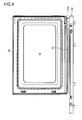
- Fig. 8 shows the back side of a door frame 50 that is a main portion of the door 11.
- the door frame 50 is a synthetic resin molding having a rectangular shape in front view.
- a window 51 through which the interior of the heating compartment can be seen is formed.
- the window 51 is shielded with a window glass formed of heat-resistant glass and a radio wave leakage prevention screen (both of which are not shown).
- a drain gutter 52 is formed near the lower edge of the back of the door frame 50.
- the drain gutter 52 is inclined downward to the right, and has an exit 52a at the right end.
- a drain pan 53 is arranged below the exit 52a. The drain pan 53 forms part of the front of the housing 10.
- the drain gutter 52 Since the drain gutter 52 is inclined downward toward the exit 52a, the condensate water received by the drain gutter 52 rapidly flows downward into the drain pan 53. Hence, the condensate water is prevented from being left on the back side of the door 11 and being dripped out of the cooker 1 when the door 11 is opened. Even when the drain gutter 52 is inclined as described above, the shape of the door 11 as seen from the front is not affected by such inclination, and its design is not disfeatured.
- the present invention can be widely utilized in cookers that perform cooking with steam.
Landscapes
- Engineering & Computer Science (AREA)
- Chemical & Material Sciences (AREA)
- Combustion & Propulsion (AREA)
- Mechanical Engineering (AREA)
- General Engineering & Computer Science (AREA)
- Electric Ovens (AREA)
- Cookers (AREA)
Abstract
A cooker (1) can feed steam to a heating compartment with a steam generation device incorporated. A water tank (15) for feeding water to the steam generation device is provided such that the water tank (15) can be drawn out from the front of a housing (10). An engagement portion (40) is formed between the water tank and the housing. When an upward force is applied to the water tank, the engagement portion is brought into an engaged state so as to prevent the water tank from being drawn out. The engagement portion is formed with a substantially U-shaped cut groove (41) formed in a wall of the housing opposite an top of the water tank and a protrusion (43) formed on the top of the water tank opposite a tongue (42) surrounded by the cut groove.
Description
- The present invention relates to cookers.
- Oven cookers that cook food put in a heating compartment thereof are widely used for commercial purposes and domestic purposes. Among them, there are a cooker that heats food with heat emitted from a heater, a cooker that heats food with hot air (convection oven), a cooker that vibrates molecules of food with high-frequency waves (microwaves) to cook the food from inside (commonly referred to as "microwave oven") and combinations of these heating systems.
- In recent cookers, steam is often combined with other heat sources to heat food. An example is disclosed in
patent document 1. -
Patent document 1 discloses a high-frequency cooker in which high-frequency waves and steam are fed into a heating compartment to heat stuff to be heated. At a lower part of the main body of the high-frequency cooker, a water tank that stores water for producing steam is arranged so that the water tank can be freely drawn out. - Patent document 1:
JP-A-2007-147275 - When a steam cooking function is added to a cooker, it is somewhat inevitable that a drawable water tank is designed such that it can be taken in and out through the front of the cooker. This is because the sides of the cooker often face a wall or another household appliance, and the top of the cooker is often used as a shelf. Incidentally, the water tank is often used as a hold when the cooker is transported. When the water tank is held to raise the cooker, if the water tank is drawn out accidentally, the cooker which has lost support at this part may drop and suffer damage. If the cooker is dropped on any part of a person's body, injury is almost inevitable.
- The present invention is made in view of the foregoing respect; an object of the present invention is to provide a cooker incorporating a drawable water tank in which, even when the water tank is held for transport of the cooker, the water tank will not be drawn out, and this makes it possible to avoid various risks caused by removal of the water tank.
- To achieve the above object, according to the present invention, in a cooker that can feed steam to a heating compartment in a housing thereof with a steam generation device incorporated therein, a water tank is provided such that the water tank can be drawn out from a front of the housing, an engagement portion is formed between the water tank and the housing and, when an upward force is applied to the water tank, the engagement portion is brought into an engaged state so as to prevent the water tank from being drawn out.
- Preferably, in the cooker configured as described above, the engagement portion is formed with a substantially U-shaped cut groove formed in a wall of the housing opposite an top of the water tank and a protrusion formed on the top of the water tank opposite a tongue surrounded by the cut groove, and, when the upward force is applied to the water tank, the protrusion bends up the tongue such that the engaged state is formed between the protrusion and the cut groove.
- In the present invention, when the cooker is raised for transport, even if the water tank is held, the upward force exerted on the water tank allows the engagement portion between the housing and the water tank of the cooker to be brought into the engaged state, and thus the water tank is prevented from being drawn out. In this way, it is possible to prevent the following accident: the water tank is drawn out, and the cooker which has lost support at this part is dropped. It is therefore possible to safely transport the cooker.
-
- [
Fig. 1 ] A front view showing an embodiment of a cooker according to the present invention; - [
Fig. 2 ] A side view of the cooker ofFig. 1 ; - [
Fig. 3 ] A side view of a front panel of the cooker and a water tank inserted thereinto; - [
Fig. 4 ] A side view of the water tank; - [
Fig. 5 ] A partially enlarged cross-sectional view of the cooker, showing the structure of an engagement portion; - [
Fig. 6 ] A partial top view of the engagement portion; - [
Fig. 7 ] A partially enlarged cross-sectional view similar toFig. 5 , showing the state of operation of the engagement portion; - [
Fig. 8 ] A back view of a door frame; and - [
Fig. 9 ] A block configuration diagram. - A structure of a
cooker 1 according to an embodiment of the present invention will be described with reference to accompanying drawings. - The
cooker 1 includes a rectangular-parallelepiped housing 10 that is formed by combination of a sheet-metal member and a synthetic resin molded member. Within thehousing 10, an unillustrated heating compartment is provided. The heating compartment has an opening portion in the front; the opening portion is closed by adoor 11. Thedoor 11 is pivoted about its left edge in a horizontal plane. - In the front of the
housing 10, on the right side of thedoor 11, asynthetic resin panel 12 is provided. In an upper portion of thepanel 12, adisplay portion 13 comprising a liquid crystal panel or the like is formed; in a lower portion of thepanel 12, anoperation portion 14 provided with a plurality of unillustrated operation keys is arranged. Below theoperation portion 14, an opening portion 16 (seeFigs. 2 and3 ) for inserting awater tank 15 into thehousing 10 is provided. Thewater tank 15 is of a drawer type, and ahandle 15a protrudes forward therefrom. Between the top of thewater tank 15 and the ceiling portion of theopening portion 16, a clearance is provided that allows thewater tank 15 to move upward, the movement of the water tank will be described later. - In the
cooker 1, heating by high-frequency waves, heating by hot air, heating by steam and heating by combination of the heating systems described above are possible. In order to realize it, thecooker 1 includes components shown inFig. 9 . - The
cooker 1 is controlled by acontroller 20. Thecontroller 20, a core part thereof is a microcomputer, receives output signals from various components and outputs control signals to various components. - In addition to the
display portion 13 and theoperation portion 14 described above, the components connected to thecontroller 20 include the followings. First, as components for performing the high-frequency heating, there are a high-frequencydrive power supply 21 that oscillates an unillustrated magnetron and anantenna motor 22 that rotates an antenna (not shown) for delivering high-frequency waves generated by the oscillation of the magnetron into the heating compartment. As components for performing the hot air heating, there are aconvection heater 23 that converts air into hot air and aconvection fan 24 that feeds the hot air into the heating compartment and circulates it. As components for performing the steam heating, there are asteam generation heater 25 that generates steam in an unillustrated steam generation device, asteam superheating heater 26 that converts the generated steam into the superheated steam and awater feed pump 27 that feeds water to the steam generation device. There is also acooling fan 28 that takes cooling air from outside in thehousing 10. - As components for outputting signals to the
controller 20, there are atemperature sensor 29 that measures a temperature within the heating compartment, ahumidity sensor 30 that measures a humidity within the heating compartment, a water-level sensor 31 that measures a water level within the steam generation device and a door-state sensor 32 that detects whether thedoor 11 is opened or closed. - When the
water tank 15 is inserted into thehousing 10, thewater tank 15 is connected to thewater feed pump 27, and thewater feed pump 27 sucks water within thewater tank 15 and feeds it to the steam generation device. Between thewater tank 15 and thehousing 10, more specifically, between thewater tank 15 and thepanel 12, an engagement portion is formed, the engagement portion is brought into an engaged state when an upward force is applied to thewater tank 15. This configuration will be described below with reference toFigs. 5 to 7 . - The
engagement portion 40 is comprised of components formed in thepanel 12 and a component formed in thewater tank 15. The components formed in thepanel 12 are a substantially U-shaped (seeFig. 6 ) cutgroove 41 formed in ahorizontal wall 12a opposite the top of thewater tank 15, and atongue 42 that is surrounded by thecut groove 41. A front end of thetongue 42 faces a user. Because of the elasticity of the synthetic resin that is the material of thepanel 12, thetongue 42 is bent when a force is applied to thetongue 42 and is restored when the force is removed. - The component formed in the
water tank 15 is aprotrusion 43 that is formed on the top of thewater tank 15. Theprotrusion 43 is triangular in cross-section thereof, and a front thereof forms a vertical wall. Theprotrusion 43 is disposed directly below thetongue 42. - When the
water tank 15 is pushed into the openingportion 16, in a normal state, as shown inFig. 5 , theengagement portion 40 is not brought into the engaged state, and thewater tank 15 can be drawn out without any problem. However, when thecooker 1 is raised in order to be transported, thewater tank 15, especially, thehandle 15a, is held, and thus an upward force indicated by the arrow ofFig. 7 is exerted on thewater tank 15. In this way, thewater tank 15 is moved upward, and theprotrusion 43 pushes up thetongue 42 and enters an opening portion that is left after the retreat of thetongue 42. - Even if the
water tank 15 is pulled forward, the vertical wall in the front of theprotrusion 43 engages with thecut groove 41, and thus thewater tank 15 is not removed from the openingportion 16. In other words, thewater tank 15 is locked. In this way, it is possible to prevent the following accident: the water tank is drawn out, and the cooker which has lost support at this part is dropped. It is therefore possible to safely transport thecooker 1. - Since the
engagement portion 40 is comprised of thetongue 42 formed in thepanel 12 by the substantiallyU-shaped cut groove 41 and theprotrusion 43 formed on the top of thewater tank 15 opposite thetongue 42, it is not necessary to add an extra component, with the result that it is possible to significantly inexpensively form theengagement portion 40. - When steam cooking is performed, a large amount of condensate water adheres to the back (the side that faces the heating compartment) of the
door 11. In order to efficiently process the condensate water, the following structure is provided on the back of thedoor 11. -
Fig. 8 shows the back side of adoor frame 50 that is a main portion of thedoor 11. Thedoor frame 50 is a synthetic resin molding having a rectangular shape in front view. In the center of thedoor frame 50, awindow 51 through which the interior of the heating compartment can be seen is formed. Thewindow 51 is shielded with a window glass formed of heat-resistant glass and a radio wave leakage prevention screen (both of which are not shown). - A
drain gutter 52 is formed near the lower edge of the back of thedoor frame 50. InFig. 8 , thedrain gutter 52 is inclined downward to the right, and has anexit 52a at the right end. Below theexit 52a, adrain pan 53 is arranged. Thedrain pan 53 forms part of the front of thehousing 10. - Since the
drain gutter 52 is inclined downward toward theexit 52a, the condensate water received by thedrain gutter 52 rapidly flows downward into thedrain pan 53. Hence, the condensate water is prevented from being left on the back side of thedoor 11 and being dripped out of thecooker 1 when thedoor 11 is opened. Even when thedrain gutter 52 is inclined as described above, the shape of thedoor 11 as seen from the front is not affected by such inclination, and its design is not disfeatured. - Although the embodiment of the present invention has been described above, the scope of the present invention is not limited to this embodiment, and many modifications are possible without departing from the spirit of the invention.
- The present invention can be widely utilized in cookers that perform cooking with steam.
-
- 1
- cooker
- 10
- housing
- 11
- door
- 12
- panel
- 13
- display portion
- 14
- operation portion
- 15
- water tank
- 15a
- handle
- 40
- engagement portion
- 41
- cut groove
- 42
- tongue
- 43
- protrusion
Claims (2)
- A cooker comprising:a housing;a heating compartment that is provided in the housing;a steam generation device that is incorporated in the housing and that feeds steam to the heating compartment; anda water tank that feeds water to the steam generation device,wherein the water tank is provided such that the water tank can be drawn out from a front of the housing,an engagement portion is formed between the water tank and the housing, andwhen an upward force is applied to the water tank, the engagement portion is brought into an engaged state so as to prevent the water tank from being drawn out.
- The cooker of claim 1,
wherein the engagement portion is formed with a substantially U-shaped cut groove formed in a wall of the housing opposite an top of the water tank and a protrusion formed on the top of the water tank opposite a tongue surrounded by the cut groove, and
when the upward force is applied to the water tank, the protrusion bends up the tongue such that the engaged state is formed between the protrusion and the cut groove.
Applications Claiming Priority (2)
| Application Number | Priority Date | Filing Date | Title |
|---|---|---|---|
| JP2010267279A JP4970586B2 (en) | 2010-11-30 | 2010-11-30 | Cooker |
| PCT/JP2011/077601 WO2012073984A1 (en) | 2010-11-30 | 2011-11-30 | Cooking device |
Publications (1)
| Publication Number | Publication Date |
|---|---|
| EP2647914A1 true EP2647914A1 (en) | 2013-10-09 |
Family
ID=46171912
Family Applications (1)
| Application Number | Title | Priority Date | Filing Date |
|---|---|---|---|
| EP11844704.4A Withdrawn EP2647914A1 (en) | 2010-11-30 | 2011-11-30 | Cooking device |
Country Status (4)
| Country | Link |
|---|---|
| EP (1) | EP2647914A1 (en) |
| JP (1) | JP4970586B2 (en) |
| CN (1) | CN103210258A (en) |
| WO (1) | WO2012073984A1 (en) |
Families Citing this family (1)
| Publication number | Priority date | Publication date | Assignee | Title |
|---|---|---|---|---|
| CN109124321B (en) * | 2018-10-29 | 2020-11-24 | 广东美的厨房电器制造有限公司 | Steam cooking appliance and control method thereof |
Family Cites Families (12)
| Publication number | Priority date | Publication date | Assignee | Title |
|---|---|---|---|---|
| JPS5444077A (en) * | 1977-09-09 | 1979-04-07 | Matsushita Electric Industrial Co Ltd | Steam oven |
| JPS54106514U (en) * | 1978-01-13 | 1979-07-26 | ||
| CN2306693Y (en) * | 1997-05-12 | 1999-02-10 | 刘成家 | drawer storage box |
| CN1747610A (en) * | 2002-06-05 | 2006-03-15 | 松下电器产业株式会社 | High-frequency heating device with steam generation function |
| JP3764412B2 (en) * | 2002-09-03 | 2006-04-05 | 松下電器産業株式会社 | Water supply tank unit |
| CN2603965Y (en) * | 2002-12-25 | 2004-02-18 | 鸿富锦精密工业(深圳)有限公司 | data access device holder |
| CN2595254Y (en) * | 2003-01-29 | 2003-12-31 | 南俊国际股份有限公司 | Improved structure of drawer slide rail |
| AT501440A1 (en) * | 2003-03-07 | 2006-09-15 | Kaindl Flooring Gmbh | COVER PLATE |
| EP1767861B1 (en) * | 2004-07-02 | 2018-10-24 | Panasonic Corporation | High frequency cookware |
| JP3966362B2 (en) | 2007-01-30 | 2007-08-29 | 松下電器産業株式会社 | High frequency cooker |
| JP2008232539A (en) * | 2007-03-20 | 2008-10-02 | Matsushita Electric Ind Co Ltd | High frequency cooker with steam generation function |
| JP5287311B2 (en) * | 2009-02-09 | 2013-09-11 | パナソニック株式会社 | Cooking device with steam generation function |
-
2010
- 2010-11-30 JP JP2010267279A patent/JP4970586B2/en not_active Expired - Fee Related
-
2011
- 2011-11-30 EP EP11844704.4A patent/EP2647914A1/en not_active Withdrawn
- 2011-11-30 CN CN201180054962XA patent/CN103210258A/en active Pending
- 2011-11-30 WO PCT/JP2011/077601 patent/WO2012073984A1/en not_active Ceased
Non-Patent Citations (1)
| Title |
|---|
| See references of WO2012073984A1 * |
Also Published As
| Publication number | Publication date |
|---|---|
| WO2012073984A1 (en) | 2012-06-07 |
| CN103210258A (en) | 2013-07-17 |
| JP4970586B2 (en) | 2012-07-11 |
| JP2012117738A (en) | 2012-06-21 |
Similar Documents
| Publication | Publication Date | Title |
|---|---|---|
| US8334482B2 (en) | Cooking range with air circulation mechanism | |
| CA2988304C (en) | Cooking apparatus | |
| EP3343109B1 (en) | Heat cooking device | |
| US8925540B2 (en) | Oven | |
| KR20160131813A (en) | cooking appliance | |
| EP2879465B1 (en) | Microwave oven | |
| EP1435493B1 (en) | Electric oven and/or microwave oven having heater | |
| EP2647914A1 (en) | Cooking device | |
| WO2015141206A1 (en) | Heating cooker | |
| WO2015141207A1 (en) | Heating cooker | |
| EP2881669A1 (en) | Heat cooking device | |
| WO2018155008A1 (en) | Heating cooking device and steam cooking method | |
| EP2068083B1 (en) | Heating unit of an oven | |
| CN101749769A (en) | Support structure of microwave oven grill | |
| US10912162B2 (en) | Packing member and cooking apparatus having the same | |
| JP5641980B2 (en) | Cooker | |
| JP2012052690A (en) | Radio frequency heating apparatus | |
| KR101732160B1 (en) | Multi functional microwave range | |
| JP2009127924A (en) | High frequency heating device | |
| EP4279816A1 (en) | Cooker | |
| JP7854585B2 (en) | heating cooker | |
| KR101531061B1 (en) | An oven range | |
| KR101702663B1 (en) | A grease cover for microwave range | |
| KR100595216B1 (en) | Microwave oven and its control method | |
| JP5896842B2 (en) | Cooker |
Legal Events
| Date | Code | Title | Description |
|---|---|---|---|
| PUAI | Public reference made under article 153(3) epc to a published international application that has entered the european phase |
Free format text: ORIGINAL CODE: 0009012 |
|
| 17P | Request for examination filed |
Effective date: 20130524 |
|
| AK | Designated contracting states |
Kind code of ref document: A1 Designated state(s): AL AT BE BG CH CY CZ DE DK EE ES FI FR GB GR HR HU IE IS IT LI LT LU LV MC MK MT NL NO PL PT RO RS SE SI SK SM TR |
|
| DAX | Request for extension of the european patent (deleted) | ||
| STAA | Information on the status of an ep patent application or granted ep patent |
Free format text: STATUS: THE APPLICATION HAS BEEN WITHDRAWN |
|
| 18W | Application withdrawn |
Effective date: 20151008 |