EP2647880A1 - Lubrication management system for a rotating shaft assembly and method of forming - Google Patents
Lubrication management system for a rotating shaft assembly and method of forming Download PDFInfo
- Publication number
- EP2647880A1 EP2647880A1 EP13162401.7A EP13162401A EP2647880A1 EP 2647880 A1 EP2647880 A1 EP 2647880A1 EP 13162401 A EP13162401 A EP 13162401A EP 2647880 A1 EP2647880 A1 EP 2647880A1
- Authority
- EP
- European Patent Office
- Prior art keywords
- lubrication
- shaft
- manipulation device
- management system
- outer diameter
- Prior art date
- Legal status (The legal status is an assumption and is not a legal conclusion. Google has not performed a legal analysis and makes no representation as to the accuracy of the status listed.)
- Granted
Links
- 238000005461 lubrication Methods 0.000 title claims abstract description 103
- 238000000034 method Methods 0.000 title claims description 14
- 239000000314 lubricant Substances 0.000 description 7
- 230000000712 assembly Effects 0.000 description 2
- 238000000429 assembly Methods 0.000 description 2
- 230000003993 interaction Effects 0.000 description 2
- 230000014759 maintenance of location Effects 0.000 description 2
- 230000004075 alteration Effects 0.000 description 1
- 238000010586 diagram Methods 0.000 description 1
- 238000006073 displacement reaction Methods 0.000 description 1
- 239000012530 fluid Substances 0.000 description 1
- 238000009434 installation Methods 0.000 description 1
- 239000008188 pellet Substances 0.000 description 1
- 230000008569 process Effects 0.000 description 1
- 230000004044 response Effects 0.000 description 1
- 230000000717 retained effect Effects 0.000 description 1
- 238000006467 substitution reaction Methods 0.000 description 1
Images


Classifications
-
- F—MECHANICAL ENGINEERING; LIGHTING; HEATING; WEAPONS; BLASTING
- F16—ENGINEERING ELEMENTS AND UNITS; GENERAL MEASURES FOR PRODUCING AND MAINTAINING EFFECTIVE FUNCTIONING OF MACHINES OR INSTALLATIONS; THERMAL INSULATION IN GENERAL
- F16H—GEARING
- F16H57/00—General details of gearing
- F16H57/04—Features relating to lubrication or cooling or heating
- F16H57/042—Guidance of lubricant
- F16H57/0427—Guidance of lubricant on rotary parts, e.g. using baffles for collecting lubricant by centrifugal force
-
- Y—GENERAL TAGGING OF NEW TECHNOLOGICAL DEVELOPMENTS; GENERAL TAGGING OF CROSS-SECTIONAL TECHNOLOGIES SPANNING OVER SEVERAL SECTIONS OF THE IPC; TECHNICAL SUBJECTS COVERED BY FORMER USPC CROSS-REFERENCE ART COLLECTIONS [XRACs] AND DIGESTS
- Y10—TECHNICAL SUBJECTS COVERED BY FORMER USPC
- Y10T—TECHNICAL SUBJECTS COVERED BY FORMER US CLASSIFICATION
- Y10T29/00—Metal working
- Y10T29/49—Method of mechanical manufacture
- Y10T29/49826—Assembling or joining
- Y10T29/49881—Assembling or joining of separate helix [e.g., screw thread]
Definitions
- the present invention relates to rotating shaft assemblies, and more particularly to a lubrication management system for such shaft assemblies, as well as a method for forming the lubrication management system.
- Various systems comprising rotating components often include a shaft to which the rotating components are mounted or operably connected to.
- the shaft typically requires lubrication proximate an outer surface to ensure intended functionality of the overall system.
- a shaft seal is not feasible and even in configurations where feasible, such seals have an inherently slight weepage. Therefore, lubrication outside of the intended contained area occurs and may undesirably interact with components of the system that function properly when kept clean of lubrication.
- a slinger is commonly installed on the shaft to centrifugally move the lubricant away from the shaft. The slinger must be retained and this is typically achieved with a separate and additional locking component. Multiple components pose installation issues and increase part count, as well as enhance the footprint on the shaft.
- a lubrication management system for a rotating shaft assembly includes a shaft rotatable about a central axis and in operable connection with at least one component, wherein lubrication is supplied proximate an outer diameter of the shaft. Also included is a lubrication manipulation device for directing the lubrication radially away from the outer diameter of the shaft, wherein the lubrication manipulation device comprises a threaded portion for fixedly securing the lubrication manipulation device to the outer diameter of the shaft.
- a method of forming a lubrication management system for a rotating shaft assembly includes operably connecting at least one component to a shaft rotatable about a central axis. Also included is fixedly securing a lubrication manipulation device to the shaft by threading the lubrication manipulation device onto an outer diameter of the shaft, wherein the lubrication manipulation device is configured to direct lubrication supplied to the outer diameter of the shaft radially away from the shaft.
- a rotating shaft assembly is generally represented with reference numeral 10 and is disposed within a system 12 that requires at least one component 14 that rotates within a system housing 16.
- the system 12 may be of various types, such as an electrical, mechanical, or electromechanical system.
- the at least one component 14 may include a variety of components typically disposed within an application, such as the system 12 described above.
- the at least one component 14 includes, but is not limited to, permanent magnet alternators (PMAs), brakes, and clutches, for example. These examples are merely illustrative and is not an exhaustive list of components that the at least one component 14 comprises. Irrespective of the particular component, it is often desirable to prevent lubrication or fluid from contacting or interacting with the at least one component 14.
- the rotating shaft assembly 10 includes a shaft 18 that is rotatable about a central axis 20 and is in operable connection with, or in close proximity to, the at least one component 14.
- a lubrication management system 21 having lubrication is supplied to various regions of the rotating shaft assembly 10, such as an outer diameter 22 of the shaft 18.
- the lubrication may be supplied from a lubrication supply circuit (not illustrated) that provides lubrication to the rotating shaft assembly 10, collects lubrication subsequent to interaction with the rotating shaft assembly 10 and recirculates the collected lubrication to provide lubrication once again to the rotating shaft assembly 10, thereby completing a lubrication recirculation process.
- a lubrication manipulation device 24, commonly referred to as a "slinger,” is fixedly secured to the shaft 18.
- the lubrication manipulation device 24 is disposed radially outward from the shaft 18 and in fitting engagement with the outer diameter 22 of the shaft 18.
- the lubrication manipulation device 24 functions to direct lubricant from regions proximate the outer diameter 22 of the shaft 18 radially outward and away from the shaft 18, such that the lubrication does not seep or flow to the at least one component 14 that is sensitive to lubricant, as discussed above.
- the lubrication manipulation device 24 is configured to rotate in a way that generates a centrifugal force sufficient to throw the lubrication radially outward through a plurality of capillaries (not illustrated) of the lubrication manipulation device 24. It is to be appreciated that the lubrication merely need be directed outward and away from the rotating shaft assembly 10, and the term radially is not intended to limit the direction of lubricant throwing to that of a 90° angle (i.e., perfectly perpendicular) from the rotating shaft assembly 10, and more particularly from the shaft 18.
- the lubrication manipulation device 24 is illustrated in greater detail. As described above, the lubrication manipulation device 24 is fixedly secured to the outer diameter 22 of the shaft 18.
- the lubrication manipulation device 24 includes a relatively planar base portion 26 that is illustrated as having a cylindrical geometry, however, it is contemplated that other geometric configurations may be employed to achieve the intended function.
- the relatively planar base portion 26 extends radially outward from a centrally located aperture 28 that is dimensioned to closely engage the outer diameter 22 of the shaft 18 to an outer surface 30. Lubricant is directed radially outward in response to centrifugal forces generated during rotation of the lubrication manipulation device 24.
- the lubricant moves radially outward along a smooth plane of the lubrication manipulation device 24 due to the centrifugal forces exerted on the lubricant.
- a threaded portion 32 that is configured to engage a threaded region 34 ( FIG. 1 ) of the outer diameter 22 of the shaft 18.
- the relatively planar base portion 26 of the lubrication manipulation device 24 is oriented in an axial plane along the shaft 18.
- a torque element 36 Extending axially from the relatively planar base portion 26 is a torque element 36 that is integrally formed with the relatively planar base portion 26, such that the lubrication manipulation device 24 comprises a single device configured to direct lubrication away from the shaft 18.
- the torque element 36 extends axially from the relatively planar base portion 26 and includes a threaded aperture 38 that is aligned with the centrally located aperture 28, such that the lubrication manipulation device 24 may be securely engaged with the shaft 18 by threading to the threaded region 34.
- Such an arrangement ensures adequate retention in the axial direction, as well as radially and circumferentially.
- the torque element 36 includes a plurality of surfaces 40 that form a nut 42 which may be engaged with a variety of tools to assist with a final torque application to the lubrication manipulation device 24.
- a locking element 44 self-retains the lubrication manipulation device 24 to the shaft 18 for adequate locking thereon.
- the locking element 44 is integrally formed with the lubrication manipulation device 24 and is configured to interact with the threaded relationship between the threaded portion 32 and the threaded region 34 during torqueing of the lubrication manipulation device 24 to the shaft 18.
- the locking element 44 may comprise a lock ring, a locking pellet, a deformed thread, etc., for example. It is to be appreciated that the examples listed above are merely illustrative and any suitable locking element may be employed to form adequate locking with the shaft 18.
- the method of forming 50 includes operably connecting 52 the at least one component 14 to the shaft 18 and fixedly securing 54 the lubrication manipulation device 24 to the shaft 18.
- the lubrication manipulation device 24 may be fixedly secured to the shaft 18, and more specifically the outer diameter 22 of the shaft 18, by threading onto the threaded region 34 of the shaft 18.
- the method of forming 50 further includes torqueing 56 the lubrication manipulation device 24 by engaging and rotating the torque element 36. Additionally, the locking element 44 ensures retention of the lubrication manipulation device 24 to the shaft and prevents displacement of the lubrication manipulation device 24 in all directions, namely axial, radial, and circumferential, with respect to the central axis 20 of the system 12.
Landscapes
- Engineering & Computer Science (AREA)
- General Engineering & Computer Science (AREA)
- Mechanical Engineering (AREA)
- General Details Of Gearings (AREA)
Abstract
Description
- The present invention relates to rotating shaft assemblies, and more particularly to a lubrication management system for such shaft assemblies, as well as a method for forming the lubrication management system.
- Various systems comprising rotating components often include a shaft to which the rotating components are mounted or operably connected to. The shaft typically requires lubrication proximate an outer surface to ensure intended functionality of the overall system. Often, a shaft seal is not feasible and even in configurations where feasible, such seals have an inherently slight weepage. Therefore, lubrication outside of the intended contained area occurs and may undesirably interact with components of the system that function properly when kept clean of lubrication. In order to keep the components free of lubrication, a slinger is commonly installed on the shaft to centrifugally move the lubricant away from the shaft. The slinger must be retained and this is typically achieved with a separate and additional locking component. Multiple components pose installation issues and increase part count, as well as enhance the footprint on the shaft.
- According to one embodiment, a lubrication management system for a rotating shaft assembly includes a shaft rotatable about a central axis and in operable connection with at least one component, wherein lubrication is supplied proximate an outer diameter of the shaft. Also included is a lubrication manipulation device for directing the lubrication radially away from the outer diameter of the shaft, wherein the lubrication manipulation device comprises a threaded portion for fixedly securing the lubrication manipulation device to the outer diameter of the shaft.
- According to another embodiment, a method of forming a lubrication management system for a rotating shaft assembly is provided. The method includes operably connecting at least one component to a shaft rotatable about a central axis. Also included is fixedly securing a lubrication manipulation device to the shaft by threading the lubrication manipulation device onto an outer diameter of the shaft, wherein the lubrication manipulation device is configured to direct lubrication supplied to the outer diameter of the shaft radially away from the shaft.
- The subject matter which is regarded as the invention is particularly pointed out and distinctly claimed in the claims at the conclusion of the specification. The foregoing and other features and advantages of the invention are apparent from the following detailed description taken in conjunction with the accompanying drawings in which:
-
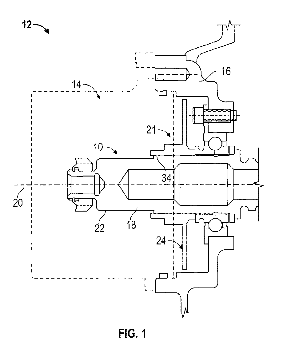
FIG. 1 is a side, cross-sectional view of a rotating shaft assembly having a lubrication management system; -
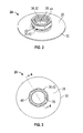
FIG. 2 is a perspective view of a lubrication manipulation device of the lubrication management system; -
FIG. 3 is a plan view of the lubrication manipulation device of the lubrication management system; -
FIG. 4 is a cross-sectional view of the lubrication manipulation device taken along line IV-IV ofFIG. 3 ; and -
FIG. 5 is a flow diagram illustrating a method of forming the lubrication management system. - Referring to
FIG. 1 , a rotating shaft assembly is generally represented withreference numeral 10 and is disposed within asystem 12 that requires at least onecomponent 14 that rotates within asystem housing 16. Thesystem 12 may be of various types, such as an electrical, mechanical, or electromechanical system. The at least onecomponent 14 may include a variety of components typically disposed within an application, such as thesystem 12 described above. Specifically, the at least onecomponent 14 includes, but is not limited to, permanent magnet alternators (PMAs), brakes, and clutches, for example. These examples are merely illustrative and is not an exhaustive list of components that the at least onecomponent 14 comprises. Irrespective of the particular component, it is often desirable to prevent lubrication or fluid from contacting or interacting with the at least onecomponent 14. - The rotating
shaft assembly 10 includes ashaft 18 that is rotatable about acentral axis 20 and is in operable connection with, or in close proximity to, the at least onecomponent 14. To enhance functionality, efficiency and service life of thesystem 12, alubrication management system 21 having lubrication is supplied to various regions of the rotatingshaft assembly 10, such as anouter diameter 22 of theshaft 18. The lubrication may be supplied from a lubrication supply circuit (not illustrated) that provides lubrication to the rotatingshaft assembly 10, collects lubrication subsequent to interaction with the rotatingshaft assembly 10 and recirculates the collected lubrication to provide lubrication once again to the rotatingshaft assembly 10, thereby completing a lubrication recirculation process. - To prevent interaction of lubrication with the at least one
component 14, alubrication manipulation device 24, commonly referred to as a "slinger," is fixedly secured to theshaft 18. Thelubrication manipulation device 24 is disposed radially outward from theshaft 18 and in fitting engagement with theouter diameter 22 of theshaft 18. Thelubrication manipulation device 24 functions to direct lubricant from regions proximate theouter diameter 22 of theshaft 18 radially outward and away from theshaft 18, such that the lubrication does not seep or flow to the at least onecomponent 14 that is sensitive to lubricant, as discussed above. Specifically, as theshaft 18 is rotating, thelubrication manipulation device 24 is configured to rotate in a way that generates a centrifugal force sufficient to throw the lubrication radially outward through a plurality of capillaries (not illustrated) of thelubrication manipulation device 24. It is to be appreciated that the lubrication merely need be directed outward and away from the rotatingshaft assembly 10, and the term radially is not intended to limit the direction of lubricant throwing to that of a 90° angle (i.e., perfectly perpendicular) from the rotatingshaft assembly 10, and more particularly from theshaft 18. - Referring now to
FIGS. 2-4 , thelubrication manipulation device 24 is illustrated in greater detail. As described above, thelubrication manipulation device 24 is fixedly secured to theouter diameter 22 of theshaft 18. In an exemplary embodiment, thelubrication manipulation device 24 includes a relativelyplanar base portion 26 that is illustrated as having a cylindrical geometry, however, it is contemplated that other geometric configurations may be employed to achieve the intended function. The relativelyplanar base portion 26 extends radially outward from a centrally locatedaperture 28 that is dimensioned to closely engage theouter diameter 22 of theshaft 18 to anouter surface 30. Lubricant is directed radially outward in response to centrifugal forces generated during rotation of thelubrication manipulation device 24. Specifically, the lubricant moves radially outward along a smooth plane of thelubrication manipulation device 24 due to the centrifugal forces exerted on the lubricant. Along the centrally locatedaperture 28 is a threaded portion 32 that is configured to engage a threaded region 34 (FIG. 1 ) of theouter diameter 22 of theshaft 18. Upon engagement with theshaft 18, the relativelyplanar base portion 26 of thelubrication manipulation device 24 is oriented in an axial plane along theshaft 18. - Extending axially from the relatively
planar base portion 26 is a torque element 36 that is integrally formed with the relativelyplanar base portion 26, such that thelubrication manipulation device 24 comprises a single device configured to direct lubrication away from theshaft 18. The torque element 36 extends axially from the relativelyplanar base portion 26 and includes a threaded aperture 38 that is aligned with the centrally locatedaperture 28, such that thelubrication manipulation device 24 may be securely engaged with theshaft 18 by threading to the threadedregion 34. Such an arrangement ensures adequate retention in the axial direction, as well as radially and circumferentially. To enhance the fixed securement of thelubrication manipulation device 24 to theshaft 18, the torque element 36 includes a plurality ofsurfaces 40 that form a nut 42 which may be engaged with a variety of tools to assist with a final torque application to thelubrication manipulation device 24. - During the secure engagement of the
lubrication manipulation device 24 to theshaft 18, alocking element 44 self-retains thelubrication manipulation device 24 to theshaft 18 for adequate locking thereon. Thelocking element 44 is integrally formed with thelubrication manipulation device 24 and is configured to interact with the threaded relationship between the threaded portion 32 and the threadedregion 34 during torqueing of thelubrication manipulation device 24 to theshaft 18. Thelocking element 44 may comprise a lock ring, a locking pellet, a deformed thread, etc., for example. It is to be appreciated that the examples listed above are merely illustrative and any suitable locking element may be employed to form adequate locking with theshaft 18. - Referring now to
FIG. 5 , a method of forming 50 thelubrication management system 21 is also provided. Thelubrication management system 21, as well as the rotatingshaft assembly 10, have been previously described and specific structural components need not be described in further detail. The method of forming 50 includes operably connecting 52 the at least onecomponent 14 to theshaft 18 and fixedly securing 54 thelubrication manipulation device 24 to theshaft 18. Thelubrication manipulation device 24 may be fixedly secured to theshaft 18, and more specifically theouter diameter 22 of theshaft 18, by threading onto the threadedregion 34 of theshaft 18. To ensure adequate locking and a fixed securement of thelubrication manipulation device 24 to theshaft 18, the method of forming 50 further includes torqueing 56 thelubrication manipulation device 24 by engaging and rotating the torque element 36. Additionally, thelocking element 44 ensures retention of thelubrication manipulation device 24 to the shaft and prevents displacement of thelubrication manipulation device 24 in all directions, namely axial, radial, and circumferential, with respect to thecentral axis 20 of thesystem 12. - While the invention has been described in detail in connection with only a limited number of embodiments, it should be readily understood that the invention is not limited to such disclosed embodiments. Rather, the invention can be modified to incorporate any number of variations, alterations, substitutions or equivalent arrangements not heretofore described, but which are commensurate with the scope of the invention. Additionally, while various embodiments of the invention have been described, it is to be understood that aspects of the invention may include only some of the described embodiments. Accordingly, the invention is not to be seen as limited by the foregoing description, but is only limited by the scope of the appended claims.
Claims (15)
- A lubrication management system for a rotating shaft assembly (10) comprising:a shaft (18) rotatable about a central axis (20) and in operable connection with at least one component (14), wherein lubrication is supplied proximate an outer diameter (22) of the shaft (18); anda lubrication manipulation device (24) for directing lubrication radially away from the outer diameter (22) of the shaft (18), wherein the lubrication manipulation device (24) comprises a threaded portion (32) for fixedly securing the lubrication manipulation device (24) to the outer diameter (22) of the shaft (18).
- The lubrication management system of claim 1, wherein the lubrication manipulation device (24) comprises a centrally located aperture (28) dimensioned to closely engage the outer diameter (22) of the shaft (18).
- The lubrication management system of claim 2, wherein the threaded portion (32) of the lubrication manipulation device (24) is disposed proximate the centrally located aperture (28).
- The lubrication management system of any preceding claim, wherein the lubrication manipulation device (24) comprises a relatively planar base (26) oriented in an axial plane along the shaft (18).
- The lubrication management system of claim 4, wherein the relatively planar base (26) is cylindrical.
- The lubrication management system of claim 4 or 5, further comprising a torque element (36) integrally formed with the lubrication manipulation device (24), wherein the locking element extends axially from the relatively planar base (26).
- The lubrication management system of claim 6, wherein the locking element comprises a threaded aperture (38) aligned with the centrally located aperture (28) of the lubrication manipulation device (24).
- The lubrication management system of claim 7, wherein the locking element further comprises a plurality of surfaces (40) forming a nut (42) for torqueing of the lubrication manipulation device (24) to the shaft (18).
- The lubrication management system of any preceding claim, wherein the at least one component (14) comprises at least one of a permanent magnet alternator, a clutch and a brake.
- The lubrication management system of any preceding claim, further comprising a locking element (44) integrally formed with the lubrication manipulation device (24), wherein the locking element (44) is disposed proximate the threaded portion (32).
- A method of forming a lubrication management system for a rotating shaft assembly (10) comprising:operably connecting at least one component to a shaft (18) rotatable about a central axis (20); andfixedly securing a lubrication manipulation device (24) to the shaft (18) by threading the lubrication manipulation device (24) onto an outer diameter (22) of the shaft (18), wherein the lubrication manipulation device (24) is configured to direct lubrication supplied to the outer diameter (22) of the shaft (18) radially away from the shaft (18).
- The method of claim 11, wherein the lubrication manipulation device (24) comprises a relatively planar base (26) oriented along an axial plane of the shaft (18).
- The method of claim 11 or 12, wherein the lubrication manipulation device further comprises a torque element (36) integrally formed with, and extending axially away from, a or the relatively planar base (26).
- The method of claim 13, wherein the torque element (36) comprises a plurality of surfaces (40) to form a nut (42).
- The method of claim 14, further comprising torqueing the lubrication manipulation device (24) to the shaft (18) by rotating the nut (42).
Applications Claiming Priority (1)
| Application Number | Priority Date | Filing Date | Title |
|---|---|---|---|
| US13/441,174 US20130267331A1 (en) | 2012-04-06 | 2012-04-06 | Lubrication management system for a rotating shaft assembly and method of forming |
Publications (2)
| Publication Number | Publication Date |
|---|---|
| EP2647880A1 true EP2647880A1 (en) | 2013-10-09 |
| EP2647880B1 EP2647880B1 (en) | 2015-03-18 |
Family
ID=48128084
Family Applications (1)
| Application Number | Title | Priority Date | Filing Date |
|---|---|---|---|
| EP13162401.7A Not-in-force EP2647880B1 (en) | 2012-04-06 | 2013-04-04 | Lubrication management system for a rotating shaft assembly and method of forming |
Country Status (3)
| Country | Link |
|---|---|
| US (1) | US20130267331A1 (en) |
| EP (1) | EP2647880B1 (en) |
| CA (1) | CA2812175A1 (en) |
Citations (2)
| Publication number | Priority date | Publication date | Assignee | Title |
|---|---|---|---|---|
| US2645305A (en) * | 1951-05-22 | 1953-07-14 | Willys Motors Inc | Means for lubricating bearings |
| WO2011142235A1 (en) * | 2010-05-08 | 2011-11-17 | 日立建機株式会社 | Swiveling device for construction machinery |
-
2012
- 2012-04-06 US US13/441,174 patent/US20130267331A1/en not_active Abandoned
-
2013
- 2013-04-04 EP EP13162401.7A patent/EP2647880B1/en not_active Not-in-force
- 2013-04-05 CA CA2812175A patent/CA2812175A1/en not_active Abandoned
Patent Citations (2)
| Publication number | Priority date | Publication date | Assignee | Title |
|---|---|---|---|---|
| US2645305A (en) * | 1951-05-22 | 1953-07-14 | Willys Motors Inc | Means for lubricating bearings |
| WO2011142235A1 (en) * | 2010-05-08 | 2011-11-17 | 日立建機株式会社 | Swiveling device for construction machinery |
Also Published As
| Publication number | Publication date |
|---|---|
| EP2647880B1 (en) | 2015-03-18 |
| CA2812175A1 (en) | 2013-10-06 |
| US20130267331A1 (en) | 2013-10-10 |
Similar Documents
| Publication | Publication Date | Title |
|---|---|---|
| EP2392477B1 (en) | Spindle nut | |
| US7211916B2 (en) | Arrangement with an electric motor | |
| CN101755139B (en) | Hub unit bearing | |
| US9689442B2 (en) | Selectable one-way clutch | |
| CN205544761U (en) | A device for inciting somebody to action rotary motion converts linear movement to | |
| US20160118855A1 (en) | Motor, Positioning Device, Conveyance Device | |
| CN104054239B (en) | motor | |
| EP2927516B1 (en) | Locking apparatus for a nut | |
| ZA201004452B (en) | Rotor for permanent magnet electric machine | |
| US20120308389A1 (en) | Locking nut assembly | |
| US6821021B2 (en) | Instrumented antifriction bearing device with temporary angular pre-indexing of the encoder relative to the sensor | |
| JP7449277B2 (en) | Method and apparatus for rolling bearing assemblies protected from electrical discharge damage | |
| CN113728172B (en) | Hub lock nut assembly | |
| CN107504045B (en) | Method and apparatus for preventing loosening of threaded fasteners | |
| EP2647880B1 (en) | Lubrication management system for a rotating shaft assembly and method of forming | |
| JP5932069B2 (en) | Spindle motor | |
| EP3631221B1 (en) | Bearing unit for a turbocharger rotor | |
| EP4643024A1 (en) | A retaining element for fastening elements or installations onto a shaft | |
| US9004871B2 (en) | Stacked wheel assembly for a turbine system and method of assembling | |
| KR20170077306A (en) | Oil seal for pump | |
| US20110203881A1 (en) | Electric parking brake | |
| US12237612B2 (en) | Electrical plug with friction brake device, as well as arrangement and method | |
| JP6804387B2 (en) | Fixing mechanism and mechanical seal | |
| JPWO2018158870A1 (en) | Motor generator | |
| JP2018204657A (en) | Gear support structure |
Legal Events
| Date | Code | Title | Description |
|---|---|---|---|
| PUAI | Public reference made under article 153(3) epc to a published international application that has entered the european phase |
Free format text: ORIGINAL CODE: 0009012 |
|
| AK | Designated contracting states |
Kind code of ref document: A1 Designated state(s): AL AT BE BG CH CY CZ DE DK EE ES FI FR GB GR HR HU IE IS IT LI LT LU LV MC MK MT NL NO PL PT RO RS SE SI SK SM TR |
|
| AX | Request for extension of the european patent |
Extension state: BA ME |
|
| 17P | Request for examination filed |
Effective date: 20140331 |
|
| RBV | Designated contracting states (corrected) |
Designated state(s): AL AT BE BG CH CY CZ DE DK EE ES FI FR GB GR HR HU IE IS IT LI LT LU LV MC MK MT NL NO PL PT RO RS SE SI SK SM TR |
|
| GRAP | Despatch of communication of intention to grant a patent |
Free format text: ORIGINAL CODE: EPIDOSNIGR1 |
|
| RIC1 | Information provided on ipc code assigned before grant |
Ipc: F16H 57/04 20100101AFI20140509BHEP |
|
| INTG | Intention to grant announced |
Effective date: 20140528 |
|
| GRAP | Despatch of communication of intention to grant a patent |
Free format text: ORIGINAL CODE: EPIDOSNIGR1 |
|
| INTG | Intention to grant announced |
Effective date: 20140926 |
|
| GRAS | Grant fee paid |
Free format text: ORIGINAL CODE: EPIDOSNIGR3 |
|
| GRAA | (expected) grant |
Free format text: ORIGINAL CODE: 0009210 |
|
| AK | Designated contracting states |
Kind code of ref document: B1 Designated state(s): AL AT BE BG CH CY CZ DE DK EE ES FI FR GB GR HR HU IE IS IT LI LT LU LV MC MK MT NL NO PL PT RO RS SE SI SK SM TR |
|
| REG | Reference to a national code |
Ref country code: GB Ref legal event code: FG4D |
|
| REG | Reference to a national code |
Ref country code: CH Ref legal event code: EP |
|
| REG | Reference to a national code |
Ref country code: IE Ref legal event code: FG4D |
|
| REG | Reference to a national code |
Ref country code: AT Ref legal event code: REF Ref document number: 716797 Country of ref document: AT Kind code of ref document: T Effective date: 20150415 |
|
| REG | Reference to a national code |
Ref country code: DE Ref legal event code: R096 Ref document number: 602013001220 Country of ref document: DE Effective date: 20150430 |
|
| REG | Reference to a national code |
Ref country code: NL Ref legal event code: VDEP Effective date: 20150318 |
|
| REG | Reference to a national code |
Ref country code: NL Ref legal event code: VDEP Effective date: 20150318 |
|
| PG25 | Lapsed in a contracting state [announced via postgrant information from national office to epo] |
Ref country code: NO Free format text: LAPSE BECAUSE OF FAILURE TO SUBMIT A TRANSLATION OF THE DESCRIPTION OR TO PAY THE FEE WITHIN THE PRESCRIBED TIME-LIMIT Effective date: 20150618 Ref country code: HR Free format text: LAPSE BECAUSE OF FAILURE TO SUBMIT A TRANSLATION OF THE DESCRIPTION OR TO PAY THE FEE WITHIN THE PRESCRIBED TIME-LIMIT Effective date: 20150318 Ref country code: FI Free format text: LAPSE BECAUSE OF FAILURE TO SUBMIT A TRANSLATION OF THE DESCRIPTION OR TO PAY THE FEE WITHIN THE PRESCRIBED TIME-LIMIT Effective date: 20150318 Ref country code: LT Free format text: LAPSE BECAUSE OF FAILURE TO SUBMIT A TRANSLATION OF THE DESCRIPTION OR TO PAY THE FEE WITHIN THE PRESCRIBED TIME-LIMIT Effective date: 20150318 Ref country code: SE Free format text: LAPSE BECAUSE OF FAILURE TO SUBMIT A TRANSLATION OF THE DESCRIPTION OR TO PAY THE FEE WITHIN THE PRESCRIBED TIME-LIMIT Effective date: 20150318 |
|
| REG | Reference to a national code |
Ref country code: AT Ref legal event code: MK05 Ref document number: 716797 Country of ref document: AT Kind code of ref document: T Effective date: 20150318 |
|
| REG | Reference to a national code |
Ref country code: LT Ref legal event code: MG4D |
|
| PG25 | Lapsed in a contracting state [announced via postgrant information from national office to epo] |
Ref country code: LV Free format text: LAPSE BECAUSE OF FAILURE TO SUBMIT A TRANSLATION OF THE DESCRIPTION OR TO PAY THE FEE WITHIN THE PRESCRIBED TIME-LIMIT Effective date: 20150318 Ref country code: GR Free format text: LAPSE BECAUSE OF FAILURE TO SUBMIT A TRANSLATION OF THE DESCRIPTION OR TO PAY THE FEE WITHIN THE PRESCRIBED TIME-LIMIT Effective date: 20150619 Ref country code: RS Free format text: LAPSE BECAUSE OF FAILURE TO SUBMIT A TRANSLATION OF THE DESCRIPTION OR TO PAY THE FEE WITHIN THE PRESCRIBED TIME-LIMIT Effective date: 20150318 |
|
| PG25 | Lapsed in a contracting state [announced via postgrant information from national office to epo] |
Ref country code: NL Free format text: LAPSE BECAUSE OF FAILURE TO SUBMIT A TRANSLATION OF THE DESCRIPTION OR TO PAY THE FEE WITHIN THE PRESCRIBED TIME-LIMIT Effective date: 20150318 |
|
| PG25 | Lapsed in a contracting state [announced via postgrant information from national office to epo] |
Ref country code: ES Free format text: LAPSE BECAUSE OF FAILURE TO SUBMIT A TRANSLATION OF THE DESCRIPTION OR TO PAY THE FEE WITHIN THE PRESCRIBED TIME-LIMIT Effective date: 20150318 Ref country code: PT Free format text: LAPSE BECAUSE OF FAILURE TO SUBMIT A TRANSLATION OF THE DESCRIPTION OR TO PAY THE FEE WITHIN THE PRESCRIBED TIME-LIMIT Effective date: 20150720 Ref country code: CZ Free format text: LAPSE BECAUSE OF FAILURE TO SUBMIT A TRANSLATION OF THE DESCRIPTION OR TO PAY THE FEE WITHIN THE PRESCRIBED TIME-LIMIT Effective date: 20150318 Ref country code: SK Free format text: LAPSE BECAUSE OF FAILURE TO SUBMIT A TRANSLATION OF THE DESCRIPTION OR TO PAY THE FEE WITHIN THE PRESCRIBED TIME-LIMIT Effective date: 20150318 Ref country code: RO Free format text: LAPSE BECAUSE OF FAILURE TO SUBMIT A TRANSLATION OF THE DESCRIPTION OR TO PAY THE FEE WITHIN THE PRESCRIBED TIME-LIMIT Effective date: 20150318 Ref country code: EE Free format text: LAPSE BECAUSE OF FAILURE TO SUBMIT A TRANSLATION OF THE DESCRIPTION OR TO PAY THE FEE WITHIN THE PRESCRIBED TIME-LIMIT Effective date: 20150318 |
|
| REG | Reference to a national code |
Ref country code: DE Ref legal event code: R119 Ref document number: 602013001220 Country of ref document: DE |
|
| PG25 | Lapsed in a contracting state [announced via postgrant information from national office to epo] |
Ref country code: IS Free format text: LAPSE BECAUSE OF FAILURE TO SUBMIT A TRANSLATION OF THE DESCRIPTION OR TO PAY THE FEE WITHIN THE PRESCRIBED TIME-LIMIT Effective date: 20150718 Ref country code: AT Free format text: LAPSE BECAUSE OF FAILURE TO SUBMIT A TRANSLATION OF THE DESCRIPTION OR TO PAY THE FEE WITHIN THE PRESCRIBED TIME-LIMIT Effective date: 20150318 Ref country code: MC Free format text: LAPSE BECAUSE OF FAILURE TO SUBMIT A TRANSLATION OF THE DESCRIPTION OR TO PAY THE FEE WITHIN THE PRESCRIBED TIME-LIMIT Effective date: 20150318 Ref country code: PL Free format text: LAPSE BECAUSE OF FAILURE TO SUBMIT A TRANSLATION OF THE DESCRIPTION OR TO PAY THE FEE WITHIN THE PRESCRIBED TIME-LIMIT Effective date: 20150318 |
|
| PLBE | No opposition filed within time limit |
Free format text: ORIGINAL CODE: 0009261 |
|
| STAA | Information on the status of an ep patent application or granted ep patent |
Free format text: STATUS: NO OPPOSITION FILED WITHIN TIME LIMIT |
|
| REG | Reference to a national code |
Ref country code: IE Ref legal event code: MM4A |
|
| PG25 | Lapsed in a contracting state [announced via postgrant information from national office to epo] |
Ref country code: DK Free format text: LAPSE BECAUSE OF FAILURE TO SUBMIT A TRANSLATION OF THE DESCRIPTION OR TO PAY THE FEE WITHIN THE PRESCRIBED TIME-LIMIT Effective date: 20150318 Ref country code: DE Free format text: LAPSE BECAUSE OF NON-PAYMENT OF DUE FEES Effective date: 20151103 |
|
| 26N | No opposition filed |
Effective date: 20151221 |
|
| PG25 | Lapsed in a contracting state [announced via postgrant information from national office to epo] |
Ref country code: SI Free format text: LAPSE BECAUSE OF FAILURE TO SUBMIT A TRANSLATION OF THE DESCRIPTION OR TO PAY THE FEE WITHIN THE PRESCRIBED TIME-LIMIT Effective date: 20150318 |
|
| REG | Reference to a national code |
Ref country code: FR Ref legal event code: PLFP Year of fee payment: 4 |
|
| PG25 | Lapsed in a contracting state [announced via postgrant information from national office to epo] |
Ref country code: IE Free format text: LAPSE BECAUSE OF NON-PAYMENT OF DUE FEES Effective date: 20150404 |
|
| PG25 | Lapsed in a contracting state [announced via postgrant information from national office to epo] |
Ref country code: BE Free format text: LAPSE BECAUSE OF FAILURE TO SUBMIT A TRANSLATION OF THE DESCRIPTION OR TO PAY THE FEE WITHIN THE PRESCRIBED TIME-LIMIT Effective date: 20150318 |
|
| REG | Reference to a national code |
Ref country code: CH Ref legal event code: PL |
|
| PG25 | Lapsed in a contracting state [announced via postgrant information from national office to epo] |
Ref country code: MT Free format text: LAPSE BECAUSE OF FAILURE TO SUBMIT A TRANSLATION OF THE DESCRIPTION OR TO PAY THE FEE WITHIN THE PRESCRIBED TIME-LIMIT Effective date: 20150318 |
|
| PG25 | Lapsed in a contracting state [announced via postgrant information from national office to epo] |
Ref country code: CH Free format text: LAPSE BECAUSE OF NON-PAYMENT OF DUE FEES Effective date: 20160430 Ref country code: LI Free format text: LAPSE BECAUSE OF NON-PAYMENT OF DUE FEES Effective date: 20160430 |
|
| REG | Reference to a national code |
Ref country code: FR Ref legal event code: PLFP Year of fee payment: 5 |
|
| PG25 | Lapsed in a contracting state [announced via postgrant information from national office to epo] |
Ref country code: BG Free format text: LAPSE BECAUSE OF FAILURE TO SUBMIT A TRANSLATION OF THE DESCRIPTION OR TO PAY THE FEE WITHIN THE PRESCRIBED TIME-LIMIT Effective date: 20150318 Ref country code: HU Free format text: LAPSE BECAUSE OF FAILURE TO SUBMIT A TRANSLATION OF THE DESCRIPTION OR TO PAY THE FEE WITHIN THE PRESCRIBED TIME-LIMIT; INVALID AB INITIO Effective date: 20130404 |
|
| PG25 | Lapsed in a contracting state [announced via postgrant information from national office to epo] |
Ref country code: CY Free format text: LAPSE BECAUSE OF FAILURE TO SUBMIT A TRANSLATION OF THE DESCRIPTION OR TO PAY THE FEE WITHIN THE PRESCRIBED TIME-LIMIT Effective date: 20150318 |
|
| PG25 | Lapsed in a contracting state [announced via postgrant information from national office to epo] |
Ref country code: TR Free format text: LAPSE BECAUSE OF FAILURE TO SUBMIT A TRANSLATION OF THE DESCRIPTION OR TO PAY THE FEE WITHIN THE PRESCRIBED TIME-LIMIT Effective date: 20150318 |
|
| PG25 | Lapsed in a contracting state [announced via postgrant information from national office to epo] |
Ref country code: LU Free format text: LAPSE BECAUSE OF NON-PAYMENT OF DUE FEES Effective date: 20150404 |
|
| REG | Reference to a national code |
Ref country code: FR Ref legal event code: PLFP Year of fee payment: 6 |
|
| PG25 | Lapsed in a contracting state [announced via postgrant information from national office to epo] |
Ref country code: SM Free format text: LAPSE BECAUSE OF FAILURE TO SUBMIT A TRANSLATION OF THE DESCRIPTION OR TO PAY THE FEE WITHIN THE PRESCRIBED TIME-LIMIT Effective date: 20150318 |
|
| PG25 | Lapsed in a contracting state [announced via postgrant information from national office to epo] |
Ref country code: MK Free format text: LAPSE BECAUSE OF FAILURE TO SUBMIT A TRANSLATION OF THE DESCRIPTION OR TO PAY THE FEE WITHIN THE PRESCRIBED TIME-LIMIT Effective date: 20150318 |
|
| PG25 | Lapsed in a contracting state [announced via postgrant information from national office to epo] |
Ref country code: AL Free format text: LAPSE BECAUSE OF FAILURE TO SUBMIT A TRANSLATION OF THE DESCRIPTION OR TO PAY THE FEE WITHIN THE PRESCRIBED TIME-LIMIT Effective date: 20150318 |
|
| PGFP | Annual fee paid to national office [announced via postgrant information from national office to epo] |
Ref country code: FR Payment date: 20230321 Year of fee payment: 11 |
|
| PGFP | Annual fee paid to national office [announced via postgrant information from national office to epo] |
Ref country code: IT Payment date: 20230322 Year of fee payment: 11 Ref country code: GB Payment date: 20230321 Year of fee payment: 11 |
|
| P01 | Opt-out of the competence of the unified patent court (upc) registered |
Effective date: 20230522 |
|
| GBPC | Gb: european patent ceased through non-payment of renewal fee |
Effective date: 20240404 |
|
| PG25 | Lapsed in a contracting state [announced via postgrant information from national office to epo] |
Ref country code: GB Free format text: LAPSE BECAUSE OF NON-PAYMENT OF DUE FEES Effective date: 20240404 |
|
| PG25 | Lapsed in a contracting state [announced via postgrant information from national office to epo] |
Ref country code: FR Free format text: LAPSE BECAUSE OF NON-PAYMENT OF DUE FEES Effective date: 20240430 |
|
| PG25 | Lapsed in a contracting state [announced via postgrant information from national office to epo] |
Ref country code: GB Free format text: LAPSE BECAUSE OF NON-PAYMENT OF DUE FEES Effective date: 20240404 Ref country code: FR Free format text: LAPSE BECAUSE OF NON-PAYMENT OF DUE FEES Effective date: 20240430 |
|
| PG25 | Lapsed in a contracting state [announced via postgrant information from national office to epo] |
Ref country code: IT Free format text: LAPSE BECAUSE OF NON-PAYMENT OF DUE FEES Effective date: 20240404 |