EP2647850A1 - Hydraulic pump control system for construction machinery - Google Patents
Hydraulic pump control system for construction machinery Download PDFInfo
- Publication number
- EP2647850A1 EP2647850A1 EP10860312.7A EP10860312A EP2647850A1 EP 2647850 A1 EP2647850 A1 EP 2647850A1 EP 10860312 A EP10860312 A EP 10860312A EP 2647850 A1 EP2647850 A1 EP 2647850A1
- Authority
- EP
- European Patent Office
- Prior art keywords
- hydraulic pump
- signal
- swing
- flow rate
- control
- Prior art date
- Legal status (The legal status is an assumption and is not a legal conclusion. Google has not performed a legal analysis and makes no representation as to the accuracy of the status listed.)
- Withdrawn
Links
- 238000010276 construction Methods 0.000 title claims description 22
- 238000001514 detection method Methods 0.000 claims abstract description 44
- 239000012530 fluid Substances 0.000 claims abstract description 28
- 238000006073 displacement reaction Methods 0.000 claims description 5
- 230000037361 pathway Effects 0.000 abstract 1
- 239000000446 fuel Substances 0.000 description 6
- 230000001133 acceleration Effects 0.000 description 3
- 238000010586 diagram Methods 0.000 description 2
- 230000000694 effects Effects 0.000 description 1
Images

Classifications
-
- F—MECHANICAL ENGINEERING; LIGHTING; HEATING; WEAPONS; BLASTING
- F15—FLUID-PRESSURE ACTUATORS; HYDRAULICS OR PNEUMATICS IN GENERAL
- F15B—SYSTEMS ACTING BY MEANS OF FLUIDS IN GENERAL; FLUID-PRESSURE ACTUATORS, e.g. SERVOMOTORS; DETAILS OF FLUID-PRESSURE SYSTEMS, NOT OTHERWISE PROVIDED FOR
- F15B11/00—Servomotor systems without provision for follow-up action; Circuits therefor
- F15B11/02—Systems essentially incorporating special features for controlling the speed or actuating force of an output member
-
- F—MECHANICAL ENGINEERING; LIGHTING; HEATING; WEAPONS; BLASTING
- F15—FLUID-PRESSURE ACTUATORS; HYDRAULICS OR PNEUMATICS IN GENERAL
- F15B—SYSTEMS ACTING BY MEANS OF FLUIDS IN GENERAL; FLUID-PRESSURE ACTUATORS, e.g. SERVOMOTORS; DETAILS OF FLUID-PRESSURE SYSTEMS, NOT OTHERWISE PROVIDED FOR
- F15B15/00—Fluid-actuated devices for displacing a member from one position to another; Gearing associated therewith
- F15B15/18—Combined units comprising both motor and pump
-
- E—FIXED CONSTRUCTIONS
- E02—HYDRAULIC ENGINEERING; FOUNDATIONS; SOIL SHIFTING
- E02F—DREDGING; SOIL-SHIFTING
- E02F9/00—Component parts of dredgers or soil-shifting machines, not restricted to one of the kinds covered by groups E02F3/00 - E02F7/00
- E02F9/08—Superstructures; Supports for superstructures
- E02F9/10—Supports for movable superstructures mounted on travelling or walking gears or on other superstructures
- E02F9/12—Slewing or traversing gears
- E02F9/121—Turntables, i.e. structure rotatable about 360°
- E02F9/123—Drives or control devices specially adapted therefor
-
- E—FIXED CONSTRUCTIONS
- E02—HYDRAULIC ENGINEERING; FOUNDATIONS; SOIL SHIFTING
- E02F—DREDGING; SOIL-SHIFTING
- E02F9/00—Component parts of dredgers or soil-shifting machines, not restricted to one of the kinds covered by groups E02F3/00 - E02F7/00
- E02F9/20—Drives; Control devices
- E02F9/22—Hydraulic or pneumatic drives
-
- E—FIXED CONSTRUCTIONS
- E02—HYDRAULIC ENGINEERING; FOUNDATIONS; SOIL SHIFTING
- E02F—DREDGING; SOIL-SHIFTING
- E02F9/00—Component parts of dredgers or soil-shifting machines, not restricted to one of the kinds covered by groups E02F3/00 - E02F7/00
- E02F9/20—Drives; Control devices
- E02F9/22—Hydraulic or pneumatic drives
- E02F9/2221—Control of flow rate; Load sensing arrangements
- E02F9/2232—Control of flow rate; Load sensing arrangements using one or more variable displacement pumps
- E02F9/2235—Control of flow rate; Load sensing arrangements using one or more variable displacement pumps including an electronic controller
-
- E—FIXED CONSTRUCTIONS
- E02—HYDRAULIC ENGINEERING; FOUNDATIONS; SOIL SHIFTING
- E02F—DREDGING; SOIL-SHIFTING
- E02F9/00—Component parts of dredgers or soil-shifting machines, not restricted to one of the kinds covered by groups E02F3/00 - E02F7/00
- E02F9/20—Drives; Control devices
- E02F9/22—Hydraulic or pneumatic drives
- E02F9/2278—Hydraulic circuits
- E02F9/2285—Pilot-operated systems
-
- E—FIXED CONSTRUCTIONS
- E02—HYDRAULIC ENGINEERING; FOUNDATIONS; SOIL SHIFTING
- E02F—DREDGING; SOIL-SHIFTING
- E02F9/00—Component parts of dredgers or soil-shifting machines, not restricted to one of the kinds covered by groups E02F3/00 - E02F7/00
- E02F9/20—Drives; Control devices
- E02F9/22—Hydraulic or pneumatic drives
- E02F9/2278—Hydraulic circuits
- E02F9/2296—Systems with a variable displacement pump
-
- F—MECHANICAL ENGINEERING; LIGHTING; HEATING; WEAPONS; BLASTING
- F04—POSITIVE - DISPLACEMENT MACHINES FOR LIQUIDS; PUMPS FOR LIQUIDS OR ELASTIC FLUIDS
- F04B—POSITIVE-DISPLACEMENT MACHINES FOR LIQUIDS; PUMPS
- F04B27/00—Multi-cylinder pumps specially adapted for elastic fluids and characterised by number or arrangement of cylinders
- F04B27/08—Multi-cylinder pumps specially adapted for elastic fluids and characterised by number or arrangement of cylinders having cylinders coaxial with, or parallel or inclined to, main shaft axis
- F04B27/14—Control
-
- F—MECHANICAL ENGINEERING; LIGHTING; HEATING; WEAPONS; BLASTING
- F15—FLUID-PRESSURE ACTUATORS; HYDRAULICS OR PNEUMATICS IN GENERAL
- F15B—SYSTEMS ACTING BY MEANS OF FLUIDS IN GENERAL; FLUID-PRESSURE ACTUATORS, e.g. SERVOMOTORS; DETAILS OF FLUID-PRESSURE SYSTEMS, NOT OTHERWISE PROVIDED FOR
- F15B13/00—Details of servomotor systems ; Valves for servomotor systems
- F15B13/02—Fluid distribution or supply devices characterised by their adaptation to the control of servomotors
- F15B13/04—Fluid distribution or supply devices characterised by their adaptation to the control of servomotors for use with a single servomotor
- F15B13/042—Fluid distribution or supply devices characterised by their adaptation to the control of servomotors for use with a single servomotor operated by fluid pressure
- F15B13/0422—Fluid distribution or supply devices characterised by their adaptation to the control of servomotors for use with a single servomotor operated by fluid pressure with manually-operated pilot valves, e.g. joysticks
-
- F—MECHANICAL ENGINEERING; LIGHTING; HEATING; WEAPONS; BLASTING
- F15—FLUID-PRESSURE ACTUATORS; HYDRAULICS OR PNEUMATICS IN GENERAL
- F15B—SYSTEMS ACTING BY MEANS OF FLUIDS IN GENERAL; FLUID-PRESSURE ACTUATORS, e.g. SERVOMOTORS; DETAILS OF FLUID-PRESSURE SYSTEMS, NOT OTHERWISE PROVIDED FOR
- F15B21/00—Common features of fluid actuator systems; Fluid-pressure actuator systems or details thereof, not covered by any other group of this subclass
- F15B21/08—Servomotor systems incorporating electrically operated control means
Definitions
- the present invention relates to a system for controlling a hydraulic pump for a construction machine, in which when swing an upper swing structure is swingably rotated with respect to a lower traveling structure of a construction machine such as an excavator or the like, the discharge flow rate of the hydraulic pump can be reduced in an operation period during which the maximum flow rate of a hydraulic fluid discharged from the hydraulic pump is not required.
- the present invention relates to a hydraulic pump control system for a construction machine, in which when an upper swing structure is abruptly swingably rotated with respect to a lower traveling structure of the construction machine, the discharge flow rate of the hydraulic pump is limited optimally so that a loss in the flow rate of a hydraulic fluid discharged from the hydraulic pump can be minimized while securing the swing acceleration to the maximum.
- a hydraulic pump control system for a construction machine includes:
- the control valve 6 is shifted by the pilot signal pressures P1 and P2 supplied from the pilot pump 2 by manipulating the remote control valve 7, so that a hydraulic fluid discharged from the hydraulic pump 1 can be transferred to the swing motor 4 via the control valve 6 to drive the swing motor 4 to cause the upper swing structure to be swingably rotated with respect to the lower traveling structure.
- the manipulation of the remote control valve 7 causes the control valve 5 to be shifted by the pilot signal pressures P3 and P4 supplied from the pilot pump 2, so that the hydraulic fluid discharged from the hydraulic pump 1 can be transferred to the boom cylinder 3 via the control valve 5 to drive the boom cylinder 3 to upward or downward move the boom.
- the flow rate of the hydraulic fluid discharged from the hydraulic pump 1 is in proportional to a manipulation angle or a pilot signal pressure of the remote control valve 7 irrespective of a load pressure generated from a work apparatus such as a boom or the like. For this reason, if a lever of the remote control valve 7 is manipulated with a full stroke or a set pilot signal pressure exceeds a predetermined pressure, the hydraulic pump 1 discharges the hydraulic fluid at the maximum flow rate.
- the flow rate of the hydraulic fluid discharged from the hydraulic pump 1 is increased in proportional to a manipulation amount of a swing manipulation lever to cause the upper swing structure to swingably rotated at a sudden acceleration with respect to the lower traveling structure. That is, the flow rate of the hydraulic fluid supplied to the swing motor 4 initially starts from “0" and is increased gradually until the swing motor 4 starts to be accelerated at its stop state and is increased in a swing speed
- a high flow rate of a hydraulic fluid is not required in an operation period from a time point when the upper swing structure starts to swing to a time point when the upper swing structure is accelerated.
- the hydraulic pump 1 discharges the maximum flow rate of a hydraulic fluid, there occurs a problem in that a flow rate loss (i.e., a shaded region in Fig. 2 ) is caused, and the amount of fuel consumed by the engine is increased to decrease the fuel efficiency of the equipment.
- the present invention was made to solve the aforementioned problem occurring in the prior art, and it is an object of the present invention to provide a hydraulic pump control system for a construction machine, in which when an operator manipulates the remote control valve abruptly to swing an upper swing structure with respect to a lower traveling structure of the construction machine, the discharge flow rate of the hydraulic pump is limited optimally so that a loss in the flow rate of a hydraulic fluid discharged from the hydraulic pump can be minimized until the upper swing structure is accelerated while securing the swing acceleration to the maximum.
- a hydraulic pump control system for a construction machine including:
- the control unit if the detection signal of the swing manipulation signal detection means is increased over a predetermined change rate or the discharge flow rate of the hydraulic pump predicted based on the detection signal of the swing manipulation signal detection means is increased over the predetermined change rate, the control unit outputs the control signal to the electro proportional pressure reducing valve so that the discharge flow rate of the hydraulic pump is limited to the predetermined change rate and thus the flow rate of a hydraulic fluid supplied to the swing motor is reduced.
- the hydraulic pump control system for a construction machine has the following advantages.
- the discharge flow rate of the hydraulic pump is limited in a specific control period from a time point when the upper swing structure starts to swing by receiving a swing manipulation signal to a time point when the upper swing structure is accelerated, and thus the flow rate of a hydraulic fluid supplied to the swing motor is reduced, thereby minimizing a flow rate loss and reducing the amount of fuel consumed by the engine to increase the fuel efficiency of the equipment.
- the hydraulic pump control system for a construction machine includes:
- the control unit 12 If the detection signal of the swing manipulation signal detection means 11 is increased over a predetermined change rate or the discharge flow rate of the hydraulic pump 1 predicted based on the detection signal of the swing manipulation signal detection means 11 is increased over the predetermined change rate, the control unit 12 outputs the control signal to the electro proportional pressure reducing valve 13 so that the discharge flow rate of the hydraulic pump 1 is limited to the predetermined change rate and thus the flow rate of a hydraulic fluid supplied to the swing motor is reduced.
- a non-explained reference numeral 5 denotes a control valve that is installed in the center bypass path 1a of the hydraulic pump 1 and controls a start, a stop, and a direction change of a boom cylinder 3 during shifting in response to the pilot signal pressures P1 and P2 generated from the remote control valve 7.
- pilot signal pressures P1 and P2 discharged from the pilot pump 2 is supplied to the control valve 6 via the remote control valve 7 to shift the internal spool.
- a hydraulic fluid discharged from the hydraulic pump 1 is supplied to the swing motor 4 via the control valve 6 to drive the swing motor 4 so that upper swing structure can be swingably rotated in a left or right direction.
- control unit 12 generates a control signal for controlling the regulator 9 for application to the electro proportional pressure reducing valve 13 to control the discharge flow rate of the hydraulic pump 1 in response to the detection signal applied thereto from the swing manipulation signal detection means 11.
- the control unit 12 outputs a proper electric current value to the electro proportional pressure reducing valve 13 so that the discharge flow rate of the hydraulic pump 1 is limited to the predetermined change rate and thus the flow rate of the hydraulic fluid supplied to the swing motor 4 is reduced.
- a secondary pressure that is in proportion to the detection signal of the swing manipulation signal detection means 11 is generated from the electro proportional pressure reducing valve 13 and is supplied to the shuttle valve 14.
- the regulator 9 is driven according to a signal pressure inputted thereto in response to a swing manipulation signal indicative of the manipulation of the remote control valve 7. That is, the discharge flow rate of the hydraulic pump 1 is limited through the control of a swivel angle of a swash plate of the hydraulic pump 1 in a specific control period from a time point when the upper swing structure starts to swing by receiving the swing manipulation signal to a time point when the upper swing structure is accelerated, and thus the flow rate of a hydraulic fluid supplied to the swing motor 4 is reduced, thereby minimizing a flow rate loss.
- the discharge flow rate of the hydraulic pump 1 is limited during a predetermined time period (e.g., 2 to 3 seconds) from a time point when the upper swing structure starts to swing by receiving the swing manipulation signal to a time point when the upper swing structure is accelerated, and thus the flow rate of a hydraulic fluid supplied to the swing motor 4 is reduced, thereby minimizing a flow rate loss and reducing the amount of fuel consumed by the engine to increase the fuel efficiency of the equipment.
- a predetermined time period e.g., 2 to 3 seconds
Landscapes
- Engineering & Computer Science (AREA)
- General Engineering & Computer Science (AREA)
- Structural Engineering (AREA)
- Mining & Mineral Resources (AREA)
- Civil Engineering (AREA)
- Fluid Mechanics (AREA)
- Physics & Mathematics (AREA)
- Mechanical Engineering (AREA)
- Chemical & Material Sciences (AREA)
- Analytical Chemistry (AREA)
- Fluid-Pressure Circuits (AREA)
- Operation Control Of Excavators (AREA)
- Control Of Positive-Displacement Pumps (AREA)
- Component Parts Of Construction Machinery (AREA)
Abstract
Description
- The present invention relates to a system for controlling a hydraulic pump for a construction machine, in which when swing an upper swing structure is swingably rotated with respect to a lower traveling structure of a construction machine such as an excavator or the like, the discharge flow rate of the hydraulic pump can be reduced in an operation period during which the maximum flow rate of a hydraulic fluid discharged from the hydraulic pump is not required.
- More particularly, the present invention relates to a hydraulic pump control system for a construction machine, in which when an upper swing structure is abruptly swingably rotated with respect to a lower traveling structure of the construction machine, the discharge flow rate of the hydraulic pump is limited optimally so that a loss in the flow rate of a hydraulic fluid discharged from the hydraulic pump can be minimized while securing the swing acceleration to the maximum.
- A hydraulic pump control system for a construction machine according to the prior art as shown in
Fig. 1 includes: - a variable displacement hydraulic pump (hereinafter, referred to as "hydraulic pump") 1 and a
pilot pump 2, which are connected to an engine; - a boom cylinder 3 and a swing motor 4, which are connected to and driven by the hydraulic pump 1;
-
control valves 5 and 6 that is installed in a center bypass path 1a of the hydraulic pump 1 and controls a start, a stop, and a direction change of the boom cylinder 3 and the swing motor 4 during shifting, respectively; - a remote control valve (RCV) 7 that supplies pilot signal pressures P3, P4, P1 and P2 to the
control valves 5 and 6 to drive the boom cylinder 3 and the swing motor 4; - an orifice 8 that is installed on the lowermost stream side of the center bypass path 1a to generate a negative signal pressure; and
- a regulator 9 that receives the signal pressure generated from the orifice 8 and controls a swivel angle of a swash plate of the hydraulic pump 1 to control a discharge flow rate of the hydraulic pump 1.
- In the hydraulic pump control system for a construction machine as constructed above, the control valve 6 is shifted by the pilot signal pressures P1 and P2 supplied from the
pilot pump 2 by manipulating the remote control valve 7, so that a hydraulic fluid discharged from the hydraulic pump 1 can be transferred to the swing motor 4 via the control valve 6 to drive the swing motor 4 to cause the upper swing structure to be swingably rotated with respect to the lower traveling structure. - In addition, the manipulation of the remote control valve 7 causes the
control valve 5 to be shifted by the pilot signal pressures P3 and P4 supplied from thepilot pump 2, so that the hydraulic fluid discharged from the hydraulic pump 1 can be transferred to the boom cylinder 3 via thecontrol valve 5 to drive the boom cylinder 3 to upward or downward move the boom. - In this case, the flow rate of the hydraulic fluid discharged from the hydraulic pump 1 is in proportional to a manipulation angle or a pilot signal pressure of the remote control valve 7 irrespective of a load pressure generated from a work apparatus such as a boom or the like. For this reason, if a lever of the remote control valve 7 is manipulated with a full stroke or a set pilot signal pressure exceeds a predetermined pressure, the hydraulic pump 1 discharges the hydraulic fluid at the maximum flow rate.
- If an operator manipulates the remote control valve 7 abruptly to drive the swing motor 4, the flow rate of the hydraulic fluid discharged from the hydraulic pump 1 is increased in proportional to a manipulation amount of a swing manipulation lever to cause the upper swing structure to swingably rotated at a sudden acceleration with respect to the lower traveling structure. That is, the flow rate of the hydraulic fluid supplied to the swing motor 4 initially starts from "0" and is increased gradually until the swing motor 4 starts to be accelerated at its stop state and is increased in a swing speed
- Meanwhile, when the upper swing structure starts to be swingably rotated abruptly with respect to the lower traveling structure, all the hydraulic fluids corresponding to a difference between a hydraulic fluid of a flow rate sucked by rotation of the swing motor 4 and a hydraulic fluid of a flow rate discharged from the hydraulic pump 1 is returned to a hydraulic tank T through a
relief valve 10 to protect the swing motor 4 and the swing structure. That is, if the hydraulic fluid of the flow rate discharged from the hydraulic pump 1 is increased to cause a discharge pressure of the hydraulic fluid to exceed a predetermined pressure of therelief valve 10, a hydraulic fluid of a flow rate other than a hydraulic fluid of the flow rate used to rotate the swing motor 4 is returned to the hydraulic tank T. - As shown in
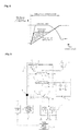
Fig. 2 , a high flow rate of a hydraulic fluid is not required in an operation period from a time point when the upper swing structure starts to swing to a time point when the upper swing structure is accelerated. On the other hand, since the hydraulic pump 1 discharges the maximum flow rate of a hydraulic fluid, there occurs a problem in that a flow rate loss (i.e., a shaded region inFig. 2 ) is caused, and the amount of fuel consumed by the engine is increased to decrease the fuel efficiency of the equipment. - Accordingly, the present invention was made to solve the aforementioned problem occurring in the prior art, and it is an object of the present invention to provide a hydraulic pump control system for a construction machine, in which when an operator manipulates the remote control valve abruptly to swing an upper swing structure with respect to a lower traveling structure of the construction machine, the discharge flow rate of the hydraulic pump is limited optimally so that a loss in the flow rate of a hydraulic fluid discharged from the hydraulic pump can be minimized until the upper swing structure is accelerated while securing the swing acceleration to the maximum.
- To accomplish the above object, in accordance with an embodiment of the present invention, there is provided a hydraulic pump control system for a construction machine, including:
- a variable displacement hydraulic pump and a pilot pump, which are connected to an engine;
- a swing motor connected to and driven by the hydraulic pump;
- a control spool installed in a center bypass path of the hydraulic pump and configured to control a start, a stop, and a direction change of the swing motor during shifting;
- a remote control valve configured to supply a pilot signal pressure for shifting to the control spool to drive the swing motor;
- an orifice installed on the lowermost stream side of the center bypass path to generate a negative signal pressure;
- a regulator configured to receive the signal pressure generated from the orifice and control a swivel angle of a swash plate of the hydraulic pump to control a discharge flow rate of the hydraulic pump;
- a swing manipulation signal detection means configured to detect a swing manipulation signal outputted from the remote control valve and output a detection signal;
- a control unit configured to output a control signal to the regulator in response to the detection signal inputted thereto from the swing manipulation signal detection means to reduce the discharge flow rate of the hydraulic pump;
- an electro proportional pressure reducing valve configured to generate a secondary pressure that is in proportion to the detection signal of the swing manipulation signal detection means, which is inputted thereto from the control unit; and
- a shuttle valve having an input side connected to the orifice and the electro proportional pressure reducing valve and an output side connected to the regulator, and configured to supply a higher pressure of the signal pressure generated from the orifice and the secondary pressure generated from the electro proportional pressure reducing valve to the regulator.
- According to a more preferable embodiment, if the detection signal of the swing manipulation signal detection means is increased over a predetermined change rate or the discharge flow rate of the hydraulic pump predicted based on the detection signal of the swing manipulation signal detection means is increased over the predetermined change rate, the control unit outputs the control signal to the electro proportional pressure reducing valve so that the discharge flow rate of the hydraulic pump is limited to the predetermined change rate and thus the flow rate of a hydraulic fluid supplied to the swing motor is reduced.
- The hydraulic pump control system for a construction machine according to an embodiment of the present invention as constructed above has the following advantages.
- When an upper swing structure is swingably rotated with respect to a lower traveling structure, the discharge flow rate of the hydraulic pump is limited in a specific control period from a time point when the upper swing structure starts to swing by receiving a swing manipulation signal to a time point when the upper swing structure is accelerated, and thus the flow rate of a hydraulic fluid supplied to the swing motor is reduced, thereby minimizing a flow rate loss and reducing the amount of fuel consumed by the engine to increase the fuel efficiency of the equipment.
- The above objects, other features and advantages of the present invention will become more apparent by describing the preferred embodiments thereof with reference to the accompanying drawings, in which:
-
Fig. 1 is a hydraulic circuit diagram of a hydraulic pump control system for a construction machine in accordance with the prior art; -
Fig. 2 is a graph illustrating the relationship between the discharge flow rate of a hydraulic pump and the pressure for the swing operation in the hydraulic pump control system for a construction machine in accordance with the prior art; and -
Fig. 3 is a hydraulic circuit diagram of a hydraulic pump control system for a construction machine in accordance with an embodiment of the present invention; -
- 1: variable displacement hydraulic pump
- 2: pilot pump
- 3: boom cylinder
- 4: swing motor
- 5, 6: control valve
- 7: remote control valve (RCV)
- 8: orifice
- 9: regulator
- 10: relief valve
- 11: swing manipulation signal detection means
- 12: control unit (V-ECU)
- 13: electro proportional pressure reducing valve (PPRV)
- 14: shuttle valve
- Hereinafter, preferred embodiments of the present invention will be described in detail with reference to the accompanying drawings. The matters defined in the description, such as the detailed construction and elements, are nothing but specific details provided to assist those of ordinary skill in the art in a comprehensive understanding of the invention, and thus the present invention is not limited to the embodiments disclosed hereinafter.
- As shown in
Fig. 3 , the hydraulic pump control system for a construction machine according to an embodiment of the present invention includes: - a variable displacement hydraulic pump (hereinafter, referred to as "hydraulic pump") 1 and a
pilot pump 2, which are connected to an engine; - a swing motor 4 that is connected to and driven by the hydraulic pump 1;
- a control valve 6 that is installed in a center bypass path 1a of the hydraulic pump 1 and controls a start, a stop, and a direction change of the swing motor 4 during shifting;
- a remote control valve (RCV) 7 that supplies pilot signal pressures P1 and P2 for shifting to the control valve 6 to drive the swing motor 4;
- an orifice 8 that is installed on the lowermost stream side of the center bypass path 1a to generate a negative signal pressure;
- a regulator 9 that receives the signal pressure generated from the orifice 8 and controls a swivel angle of a swash plate of the hydraulic pump 1 to control a discharge flow rate of the hydraulic pump 1;
- a swing manipulation signal detection means 11 that detects a swing manipulation signal outputted from the remote control valve 7 and outputs a detection signal;
- a control unit (V-ECU) 12 that outputs a control signal to the regulator 9 in response to the detection signal inputted thereto from the swing manipulation signal detection means 11 to reduce the discharge flow rate of the hydraulic pump 1;
- an electro proportional pressure reducing valve (PPRV) 13 that is generates a secondary pressure that is in proportion to the detection signal of the swing manipulation signal detection means 11, which is inputted thereto from the
control unit 12; and - a
shuttle valve 14 that has an input side connected to the orifice 8 and the electro proportionalpressure reducing valve 13 and an output side connected to the regulator 9, and supplies a higher pressure of the signal pressure generated from the orifice 8 and the secondary pressure generated from the electro proportionalpressure reducing valve 13 to the regulator 9. - If the detection signal of the swing manipulation signal detection means 11 is increased over a predetermined change rate or the discharge flow rate of the hydraulic pump 1 predicted based on the detection signal of the swing manipulation signal detection means 11 is increased over the predetermined change rate, the
control unit 12 outputs the control signal to the electro proportionalpressure reducing valve 13 so that the discharge flow rate of the hydraulic pump 1 is limited to the predetermined change rate and thus the flow rate of a hydraulic fluid supplied to the swing motor is reduced. In the drawings, anon-explained reference numeral 5 denotes a control valve that is installed in the center bypass path 1a of the hydraulic pump 1 and controls a start, a stop, and a direction change of a boom cylinder 3 during shifting in response to the pilot signal pressures P1 and P2 generated from the remote control valve 7. - Hereinafter, a use example of the hydraulic pump control system for a construction machine according to an embodiment of the present invention will be described in detail with reference to the companying drawings.
- As shown in
Fig. 3 , when a remote control valve 7 is manipulated to swing an upper swing structure with respect to a lower traveling structure of a construction machine such as an excavator or the like, pilot signal pressures P1 and P2 discharged from thepilot pump 2 is supplied to the control valve 6 via the remote control valve 7 to shift the internal spool. - Thus, a hydraulic fluid discharged from the hydraulic pump 1 is supplied to the swing motor 4 via the control valve 6 to drive the swing motor 4 so that upper swing structure can be swingably rotated in a left or right direction.
- Meanwhile, if an operator manipulates the remote control valve 7 abruptly, a detection signal detected by the swing manipulation signal detection means 11 is applied to the
control unit 12. - Accordingly, the
control unit 12 generates a control signal for controlling the regulator 9 for application to the electro proportionalpressure reducing valve 13 to control the discharge flow rate of the hydraulic pump 1 in response to the detection signal applied thereto from the swing manipulation signal detection means 11. - That is, if the detection signal of the swing manipulation signal detection means 11 is increased over a predetermined change rate or the discharge flow rate of the hydraulic pump 1 predicted based on the detection signal of the swing manipulation signal detection means 11 is increased over the predetermined change rate, the
control unit 12 outputs a proper electric current value to the electro proportionalpressure reducing valve 13 so that the discharge flow rate of the hydraulic pump 1 is limited to the predetermined change rate and thus the flow rate of the hydraulic fluid supplied to the swing motor 4 is reduced. - Then, a secondary pressure that is in proportion to the detection signal of the swing manipulation signal detection means 11 is generated from the electro proportional
pressure reducing valve 13 and is supplied to theshuttle valve 14. - In the meantime, the abrupt manipulation of the remote control valve 7 by the operator causes the amount of the hydraulic fluid discharged from the hydraulic pump 1 to be increased, so that a signal pressure generated from the orifice 8 installed on the lowermost stream side of the center bypass path 1a is supplied to the
shuttle valve 14. - Thus, a relatively high pressure of the signal pressure generated from the orifice 8 and the secondary pressure generated from the electro proportional
pressure reducing valve 13 is supplied to the regulator 9. - As described above, if s the remote control valve 7 is manipulated abruptly by the operator, the regulator 9 is driven according to a signal pressure inputted thereto in response to a swing manipulation signal indicative of the manipulation of the remote control valve 7. That is, the discharge flow rate of the hydraulic pump 1 is limited through the control of a swivel angle of a swash plate of the hydraulic pump 1 in a specific control period from a time point when the upper swing structure starts to swing by receiving the swing manipulation signal to a time point when the upper swing structure is accelerated, and thus the flow rate of a hydraulic fluid supplied to the swing motor 4 is reduced, thereby minimizing a flow rate loss.
- In the hydraulic pump control system for a construction machine according to an embodiment of the present invention as constructed above, even in the case where an operator manipulates the remote control valve 7 abruptly to swing an upper swing structure with respect to a lower traveling structure of the construction machine,
- That is, the discharge flow rate of the hydraulic pump 1 is limited during a predetermined time period (e.g., 2 to 3 seconds) from a time point when the upper swing structure starts to swing by receiving the swing manipulation signal to a time point when the upper swing structure is accelerated, and thus the flow rate of a hydraulic fluid supplied to the swing motor 4 is reduced, thereby minimizing a flow rate loss and reducing the amount of fuel consumed by the engine to increase the fuel efficiency of the equipment.
Claims (2)
- A hydraulic pump control system for a construction machine comprising:a variable displacement hydraulic pump and a pilot pump, which are connected to an engine;a swing motor connected to and driven by the hydraulic pump;a control spool installed in a center bypass path of the hydraulic pump and configured to control a start, a stop, and a direction change of the swing motor during shifting;a remote control valve configured to supply a pilot signal pressure for shifting to the control spool to drive the swing motor;an orifice installed on the lowermost stream side of the center bypass path to generate a negative signal pressure;a regulator configured to receive the signal pressure generated from the orifice and control a swivel angle of a swash plate of the hydraulic pump to control a discharge flow rate of the hydraulic pump;a swing manipulation signal detection means configured to detect a swing manipulation signal outputted from the remote control valve and output a detection signal;a control unit configured to output a control signal to the regulator in response to the detection signal inputted thereto from the swing manipulation signal detection means to reduce the discharge flow rate of the hydraulic pump;an electro proportional pressure reducing valve configured to generate a secondary pressure that is in proportion to the detection signal of the swing manipulation signal detection means, which is inputted thereto from the control unit; anda shuttle valve having an input side connected to the orifice and the electro proportional pressure reducing valve and an output side connected to the regulator, and configured to supply a higher pressure of the signal pressure generated from the orifice and the secondary pressure generated from the electro proportional pressure reducing valve to the regulator.
- The hydraulic pump control system for a construction machine according to claim 1, wherein if the detection signal of the swing manipulation signal detection means is increased over a predetermined change rate or the discharge flow rate of the hydraulic pump predicted based on the detection signal of the swing manipulation signal detection means is increased over the predetermined change rate, the control unit outputs the control signal to the electro proportional pressure reducing valve so that the discharge flow rate of the hydraulic pump is limited to the predetermined change rate and thus the flow rate of a hydraulic fluid supplied to the swing motor is reduced.
Applications Claiming Priority (1)
| Application Number | Priority Date | Filing Date | Title |
|---|---|---|---|
| PCT/KR2010/008501 WO2012074145A1 (en) | 2010-11-30 | 2010-11-30 | Hydraulic pump control system for construction machinery |
Publications (2)
| Publication Number | Publication Date |
|---|---|
| EP2647850A1 true EP2647850A1 (en) | 2013-10-09 |
| EP2647850A4 EP2647850A4 (en) | 2017-05-24 |
Family
ID=46172060
Family Applications (1)
| Application Number | Title | Priority Date | Filing Date |
|---|---|---|---|
| EP10860312.7A Withdrawn EP2647850A4 (en) | 2010-11-30 | 2010-11-30 | Hydraulic pump control system for construction machinery |
Country Status (6)
| Country | Link |
|---|---|
| US (1) | US9400003B2 (en) |
| EP (1) | EP2647850A4 (en) |
| JP (1) | JP2013545948A (en) |
| KR (1) | KR20130143585A (en) |
| CN (1) | CN103221695B (en) |
| WO (1) | WO2012074145A1 (en) |
Families Citing this family (9)
| Publication number | Priority date | Publication date | Assignee | Title |
|---|---|---|---|---|
| CN103047204B (en) * | 2013-01-05 | 2015-06-17 | 中联重科股份有限公司 | Construction machinery and its hydraulic control operating system and method |
| KR101822931B1 (en) * | 2013-02-06 | 2018-01-29 | 볼보 컨스트럭션 이큅먼트 에이비 | Swing Control System For Construction Machines |
| EP3015608A4 (en) | 2013-06-28 | 2017-04-12 | Volvo Construction Equipment AB | Hydraulic pressure control device for construction machinery |
| CN105240349B (en) * | 2015-09-21 | 2018-01-26 | 北京中车重工机械有限公司 | A kind of rotary drilling rig and its hydraulic control system |
| WO2017105133A1 (en) * | 2015-12-16 | 2017-06-22 | 두산인프라코어 주식회사 | Device for reducing impact during traveling of construction machine and method for controlling construction machine using same |
| CN107061382B (en) * | 2017-04-10 | 2018-06-19 | 太原理工大学 | Positive flow imports and exports independent composite control hydraulic system |
| JP6807293B2 (en) | 2017-09-26 | 2021-01-06 | 日立建機株式会社 | Work machine |
| JP7478678B2 (en) * | 2021-01-21 | 2024-05-07 | 株式会社小松製作所 | Tracked work machine |
| JP7804475B2 (en) * | 2022-02-02 | 2026-01-22 | 株式会社小松製作所 | Tracked work machine |
Family Cites Families (18)
| Publication number | Priority date | Publication date | Assignee | Title |
|---|---|---|---|---|
| KR910009257B1 (en) | 1985-09-07 | 1991-11-07 | 히다찌 겡끼 가부시기가이샤 | Hydraulic Construction Machinery Control System |
| JP2871871B2 (en) | 1991-01-24 | 1999-03-17 | 日立建機株式会社 | Hydraulic drive for construction machinery |
| JPH04300402A (en) | 1991-03-28 | 1992-10-23 | Hitachi Constr Mach Co Ltd | Variable delivery type, hydraulic pump controller |
| JP3513172B2 (en) | 1993-03-12 | 2004-03-31 | 東芝機械株式会社 | Hydraulic control device |
| JP3414945B2 (en) * | 1996-09-02 | 2003-06-09 | コベルコ建機株式会社 | Construction machine control circuit |
| JP2002021808A (en) | 2000-07-10 | 2002-01-23 | Shin Caterpillar Mitsubishi Ltd | Fluid pressure circuit for work machine |
| JP2002129602A (en) * | 2000-10-25 | 2002-05-09 | Shin Caterpillar Mitsubishi Ltd | Construction machine with crane function |
| KR100813774B1 (en) | 2001-12-31 | 2008-03-13 | 두산인프라코어 주식회사 | Hydraulic Pump Control System of Small Excavator |
| JP2004028264A (en) | 2002-06-27 | 2004-01-29 | Sumitomo (Shi) Construction Machinery Manufacturing Co Ltd | Hydraulic circuit of crane specification hydraulic shovel |
| JP3946176B2 (en) * | 2003-08-08 | 2007-07-18 | 住友建機製造株式会社 | Hydraulic circuit of excavator |
| KR100964113B1 (en) | 2003-11-24 | 2010-06-16 | 두산인프라코어 주식회사 | Slewing Control Device of Excavator |
| JP4151597B2 (en) * | 2004-03-31 | 2008-09-17 | コベルコ建機株式会社 | Hydraulic control circuit and construction machinery |
| KR101164669B1 (en) | 2004-06-17 | 2012-07-11 | 두산인프라코어 주식회사 | Method of and apparatus for controlling swing operation of an excavator |
| JP2006290561A (en) * | 2005-04-12 | 2006-10-26 | Shin Caterpillar Mitsubishi Ltd | Crane operating control device |
| JP2008032175A (en) * | 2006-07-31 | 2008-02-14 | Shin Caterpillar Mitsubishi Ltd | Fluid-pressure circuit |
| JP4884124B2 (en) | 2006-08-07 | 2012-02-29 | 住友建機株式会社 | Hydraulic control circuit for construction machinery |
| JP2011021694A (en) | 2009-07-16 | 2011-02-03 | Caterpillar Sarl | Revolution hydraulic control device for working machine |
| JP2012007656A (en) | 2010-06-23 | 2012-01-12 | Caterpillar Sarl | Turning hydraulic control device for working machine |
-
2010
- 2010-11-30 WO PCT/KR2010/008501 patent/WO2012074145A1/en not_active Ceased
- 2010-11-30 CN CN201080070303.0A patent/CN103221695B/en not_active Expired - Fee Related
- 2010-11-30 EP EP10860312.7A patent/EP2647850A4/en not_active Withdrawn
- 2010-11-30 US US13/989,110 patent/US9400003B2/en not_active Expired - Fee Related
- 2010-11-30 KR KR1020137012101A patent/KR20130143585A/en not_active Ceased
- 2010-11-30 JP JP2013541879A patent/JP2013545948A/en active Pending
Non-Patent Citations (1)
| Title |
|---|
| See references of WO2012074145A1 * |
Also Published As
| Publication number | Publication date |
|---|---|
| CN103221695B (en) | 2015-11-25 |
| EP2647850A4 (en) | 2017-05-24 |
| US20130239560A1 (en) | 2013-09-19 |
| CN103221695A (en) | 2013-07-24 |
| US9400003B2 (en) | 2016-07-26 |
| KR20130143585A (en) | 2013-12-31 |
| WO2012074145A1 (en) | 2012-06-07 |
| JP2013545948A (en) | 2013-12-26 |
Similar Documents
| Publication | Publication Date | Title |
|---|---|---|
| US9400003B2 (en) | Hydraulic pump control system for construction machinery | |
| EP2719902A1 (en) | Hydraulic system for construction machinery | |
| KR101568440B1 (en) | Controller of hybrid construction machine | |
| US8510000B2 (en) | Hybrid construction machine | |
| KR101273086B1 (en) | Control device for hybrid construction machine | |
| US9037356B2 (en) | Control device for hybrid construction machine | |
| CN103003498B (en) | For controlling the system of the hydraulic pump in construction machinery | |
| US9651063B2 (en) | Priority control system for construction machine | |
| CN104487716B (en) | Hydraulic system for construction machine | |
| KR101568441B1 (en) | Controller of hybrid construction machine | |
| CN102245907B (en) | Fluid flow control apparatus for hydraulic pump of construction machine | |
| EP2738395A1 (en) | Hydraulic system for construction machinery | |
| US9026297B2 (en) | Control system for hybrid construction machine | |
| CN103562565A (en) | Rotary work machine | |
| WO2001075309A1 (en) | Pump control method and pump control device | |
| CN104364536B (en) | The control system of hybrid construction machine | |
| US20180291935A1 (en) | Hydraulic drive system of construction machine | |
| US20130263583A1 (en) | Method of controlling the flow rate of a variable capacity hydraulic pump for a construction apparatus | |
| EP2631495A1 (en) | Hydraulic system for a construction machine | |
| EP2840261A1 (en) | Hydraulic system for construction equipment | |
| CN104334871B (en) | Control systems for hybrid construction machines | |
| JP2011226491A (en) | Turning hydraulic circuit of hydraulic shovel | |
| US10107310B2 (en) | Hydraulic drive system | |
| JP5265595B2 (en) | Control device for hybrid construction machine | |
| KR20180026886A (en) | Hydraulic Pump Flow control system in Construction Equipment |
Legal Events
| Date | Code | Title | Description |
|---|---|---|---|
| PUAI | Public reference made under article 153(3) epc to a published international application that has entered the european phase |
Free format text: ORIGINAL CODE: 0009012 |
|
| 17P | Request for examination filed |
Effective date: 20130527 |
|
| AK | Designated contracting states |
Kind code of ref document: A1 Designated state(s): AL AT BE BG CH CY CZ DE DK EE ES FI FR GB GR HR HU IE IS IT LI LT LU LV MC MK MT NL NO PL PT RO RS SE SI SK SM TR |
|
| RIN1 | Information on inventor provided before grant (corrected) |
Inventor name: BANG, SANG-HO Inventor name: KIM, MI-OK |
|
| DAX | Request for extension of the european patent (deleted) | ||
| RA4 | Supplementary search report drawn up and despatched (corrected) |
Effective date: 20170426 |
|
| RIC1 | Information provided on ipc code assigned before grant |
Ipc: E02F 9/12 20060101ALI20170420BHEP Ipc: E02F 9/22 20060101ALI20170420BHEP Ipc: F15B 13/042 20060101ALI20170420BHEP Ipc: F15B 9/08 20060101AFI20170420BHEP Ipc: F15B 15/18 20060101ALI20170420BHEP Ipc: F15B 13/02 20060101ALI20170420BHEP |
|
| STAA | Information on the status of an ep patent application or granted ep patent |
Free format text: STATUS: THE APPLICATION IS DEEMED TO BE WITHDRAWN |
|
| 18D | Application deemed to be withdrawn |
Effective date: 20171123 |