EP2647801B1 - Bearing cooling system for flexible shaft turbomachine - Google Patents
Bearing cooling system for flexible shaft turbomachine Download PDFInfo
- Publication number
- EP2647801B1 EP2647801B1 EP13159987.0A EP13159987A EP2647801B1 EP 2647801 B1 EP2647801 B1 EP 2647801B1 EP 13159987 A EP13159987 A EP 13159987A EP 2647801 B1 EP2647801 B1 EP 2647801B1
- Authority
- EP
- European Patent Office
- Prior art keywords
- turbomachine
- cooling
- shaft assembly
- turbine
- wheel
- Prior art date
- Legal status (The legal status is an assumption and is not a legal conclusion. Google has not performed a legal analysis and makes no representation as to the accuracy of the status listed.)
- Active
Links
Images




Classifications
-
- F—MECHANICAL ENGINEERING; LIGHTING; HEATING; WEAPONS; BLASTING
- F01—MACHINES OR ENGINES IN GENERAL; ENGINE PLANTS IN GENERAL; STEAM ENGINES
- F01D—NON-POSITIVE DISPLACEMENT MACHINES OR ENGINES, e.g. STEAM TURBINES
- F01D25/00—Component parts, details, or accessories, not provided for in, or of interest apart from, other groups
- F01D25/08—Cooling; Heating; Heat-insulation
- F01D25/12—Cooling
- F01D25/125—Cooling of bearings
-
- F—MECHANICAL ENGINEERING; LIGHTING; HEATING; WEAPONS; BLASTING
- F01—MACHINES OR ENGINES IN GENERAL; ENGINE PLANTS IN GENERAL; STEAM ENGINES
- F01D—NON-POSITIVE DISPLACEMENT MACHINES OR ENGINES, e.g. STEAM TURBINES
- F01D25/00—Component parts, details, or accessories, not provided for in, or of interest apart from, other groups
- F01D25/16—Arrangement of bearings; Supporting or mounting bearings in casings
- F01D25/162—Bearing supports
- F01D25/164—Flexible supports; Vibration damping means associated with the bearing
-
- F—MECHANICAL ENGINEERING; LIGHTING; HEATING; WEAPONS; BLASTING
- F02—COMBUSTION ENGINES; HOT-GAS OR COMBUSTION-PRODUCT ENGINE PLANTS
- F02C—GAS-TURBINE PLANTS; AIR INTAKES FOR JET-PROPULSION PLANTS; CONTROLLING FUEL SUPPLY IN AIR-BREATHING JET-PROPULSION PLANTS
- F02C7/00—Features, components parts, details or accessories, not provided for in, or of interest apart form groups F02C1/00 - F02C6/00; Air intakes for jet-propulsion plants
- F02C7/06—Arrangements of bearings; Lubricating
-
- F—MECHANICAL ENGINEERING; LIGHTING; HEATING; WEAPONS; BLASTING
- F05—INDEXING SCHEMES RELATING TO ENGINES OR PUMPS IN VARIOUS SUBCLASSES OF CLASSES F01-F04
- F05D—INDEXING SCHEME FOR ASPECTS RELATING TO NON-POSITIVE-DISPLACEMENT MACHINES OR ENGINES, GAS-TURBINES OR JET-PROPULSION PLANTS
- F05D2240/00—Components
- F05D2240/50—Bearings
- F05D2240/52—Axial thrust bearings
-
- Y—GENERAL TAGGING OF NEW TECHNOLOGICAL DEVELOPMENTS; GENERAL TAGGING OF CROSS-SECTIONAL TECHNOLOGIES SPANNING OVER SEVERAL SECTIONS OF THE IPC; TECHNICAL SUBJECTS COVERED BY FORMER USPC CROSS-REFERENCE ART COLLECTIONS [XRACs] AND DIGESTS
- Y02—TECHNOLOGIES OR APPLICATIONS FOR MITIGATION OR ADAPTATION AGAINST CLIMATE CHANGE
- Y02T—CLIMATE CHANGE MITIGATION TECHNOLOGIES RELATED TO TRANSPORTATION
- Y02T50/00—Aeronautics or air transport
- Y02T50/60—Efficient propulsion technologies, e.g. for aircraft
Definitions
- the present invention relates to bearing cooling for high speed turbomachinery
- Aircraft environmental control systems incorporate an air cycle machine, also referred to as an air cycle cooling turbine, for use in cooling and dehumidifying air for supply to the aircraft cabin for occupant comfort.
- an air cycle machine also referred to as an air cycle cooling turbine
- the air to be conditioned in the air cycle machine is typically compressed air bled from one or more of the compressor stages of the turbine engine.
- This bleed air is passed through the air cycle machine compressor wherein it is further compressed and then passed through a series of heat exchangers including a condensing heat exchanger to cool the compressed air sufficiently to dehumidify it.
- the compressed bleed air being supplied to the compressor of the air cycle machine is typically precooled by passing it through a precooling heat exchanger.
- the expanded and precooled turbine exhaust air is expanded in a second turbine to further cool the expanded air to a desired temperature for supply to the cabin as conditioned cooling air.
- an air cycle machine must have four wheels, i.e. two turbines, a compressor and a fan.
- a shaft is supported on more than two journal bearings it is desirable to introduce a flexible link in the shaft so that the shaft may be constructed with a bending critical speed that is lower than a normal rotational speed of the turbomachine.
- Such a turbomachine is described in US Patent Application Publication No.
- US5249934 discloses a turbomachine with the features of the preamble of claim 1, describing in particular an air cycle machine with a plurality of wheels mounted on a common shaft for rotation therewith about a longitudinal axis, including a compressor rotor and a turbine rotor mounted to a central portion of the shaft in back to back relationship, the turbine rotor being operative to extract energy from a flow of compressed air for driving the shaft, and the compressor rotor, in rotation about the axis.
- EP0547279 discloses an air cycle machine with hydrodynamic bearings, the mass flow rate of coolant passing through a series of bearings is metered before the coolant passes through the final bearing.
- US5857835 discloses a rotor disc with an axially enlarged hub portion with a bore through which a turbine shaft extends in a coaxial, radially spaced apart relationship, the annular gap between the hub portion and the shaft receives a flow of temperature regulating fluid.
- a turbomachine that is constructed with three journal bearings may be constructed with two thrust bearings. All of these journal and thrust bearings may require cooling during operation of the turbomachine. Typically such cooling is provided with gas flow from one of the turbines. The cooling gas flow may be directed to the bearings through a complex combination of external tubing and internal passageways.
- the term "flexible”, as it refers to a flexible link, is a relative term referring to a link connecting two shafts, wherein the flexible link may have a greater propensity for bending than the shaft itself.
- a “flexible link” may be flexible enough to lower a bending critical speed below the operating speed of a rotating machine.
- the turbomachine 10 may include, as rotating components, a fan 12, a compressor 14 and first and second turbines 16, 18.
- the turbomachine 10 includes bearings, such as journal bearings 20, 22 and 24 and thrust bearings 30.
- the rotating components are mounted on a shaft assembly 26.
- At least a portion of the shaft assembly 26 may include a flexible link 28.
- the shaft assembly 26 is held together with a tie rod 29.
- the flexible link 28 may be positioned between the fan 12 and the compressor 14.
- FIG. 2 there is shown a pattern of cooling gas flow passageways which may carry cooling gas from the turbine 16 to the thrust bearings 30 (See Figure 1 ) and the journal bearings 20, 22 and 24.
- a turbineexit passageway 32 may be interconnected with bearing-input passageways 34 and 36.
- the passageway 36 may be interconnected with a bearing chamber 38 which may carry cooling gas to the journal bearing 20.
- the passageway 34 may be interconnected with bearing chamber 40 which may carry cooling gas to the journal bearing 22 and two thrust bearings 30 adjacent the bearing 22.
- the bearing chamber 40 is interconnected with a transitional passageway 42 which carries cooling gas into an axially-oriented, cooling-gas passageway 44.
- a second transitional passageway 46 interconnects the passageway 44 with a bearing chamber 48 within which cooling gas cools the journal bearing 24.
- the passageway 44 passes axially along an interior of the shaft assembly 26.
- the passageway 44 passes through one or more aerodynamic components of the machine 10.
- the aerodynamic component through which passageway 44 passes is the wheel 16-1 of the turbine 16.
- a cooling gas passageway passes through other ones of the aerodynamic components of the machine 10, e.g., impellers 14-1 or 12-1 of the compressor 14 or fan 12.
- the passageway 44 includes one or more sub-passageways.
- the sub-passageways are grooves 52 formed at an interface between the turbine wheel 16-1 and a portion of the shaft assembly 26.
- the grooves 52 are formed in the turbine wheel 16-1.
- Advantageously such an arrangement allows for an enlarged portion 50 of the tie rod 29 to be tightly engageable with the wheel 16-1, thus providing desirable dynamic stability for the shaft assembly 26. In other words, cooling gas flows past the wheel 16-1 even though the wheel 16-1 is tightly engaged with the enlarged portion 50 of the tie rod 29.
- the cooling gas may be air.
- the turbomachine 10 may differ from machines that may utilize gaseous refrigerant as a cooling gas. Cooling bearings with air as compared to refrigerant may require a higher volumetric flow rate of air as compared to that of refrigerant because the density of air is lower than that of gaseous refrigerant at an equivalent pressure.
- the grooves 52 in the wheel 16-1 may be made large enough to accommodate a required amount of gas flow that may be needed to fully cool the bearings 24 even though the cooling gas may be air and not gaseous refrigerant. In an exemplary embodiment, sufficient gas flow may be attained with three of the grooves 52 that may be semicircular in cross-section with a radius of about 0.635 cm to about 1.27 cm (0.25 inch to about 0.50 inch).
- a flow chart 500 may illustrate an exemplary embodiment of a method for cooling bearings in a turbomachine.
- cooling gas may be extracted from a turbine (e.g., air may be extracted from the turbine 16 and directed into the passageway 34).
- the cooling gas may be passed in a first bearing chamber (e.g., the cooling gas may emerge from the passageway 34 into the bearing chamber 40).
- the cooling gas may be passed to a second bearing chamber through grooves in a wheel or impeller (e.g., the cooling gas may emerge from the bearing chamber 40, enter a transitional passageway 42, pass through grooves 52 formed in the wheel 16-1 of the turbine 16 and then enter the bearing chamber 48).
Landscapes
- Engineering & Computer Science (AREA)
- Mechanical Engineering (AREA)
- General Engineering & Computer Science (AREA)
- Chemical & Material Sciences (AREA)
- Combustion & Propulsion (AREA)
- Structures Of Non-Positive Displacement Pumps (AREA)
- Mounting Of Bearings Or Others (AREA)
Description
- The present invention relates to bearing cooling for high speed turbomachinery
- Aircraft environmental control systems incorporate an air cycle machine, also referred to as an air cycle cooling turbine, for use in cooling and dehumidifying air for supply to the aircraft cabin for occupant comfort. On aircraft powered by turbine engines, the air to be conditioned in the air cycle machine is typically compressed air bled from one or more of the compressor stages of the turbine engine. This bleed air is passed through the air cycle machine compressor wherein it is further compressed and then passed through a series of heat exchangers including a condensing heat exchanger to cool the compressed air sufficiently to dehumidify it. The compressed bleed air being supplied to the compressor of the air cycle machine is typically precooled by passing it through a precooling heat exchanger.
- The expanded and precooled turbine exhaust air is expanded in a second turbine to further cool the expanded air to a desired temperature for supply to the cabin as conditioned cooling air. To be suitable for use in such an air conditioning system of an aircraft, an air cycle machine must have four wheels, i.e. two turbines, a compressor and a fan. To achieve optimal aerodynamic efficiency, there is a need to utilize more than two journal bearings to support a shaft that connects the four wheels. When a shaft is supported on more than two journal bearings it is desirable to introduce a flexible link in the shaft so that the shaft may be constructed with a bending critical speed that is lower than a normal rotational speed of the turbomachine. Such a turbomachine is described in
US Patent Application Publication No. 20110135463 dated June 9, 2011 .US5249934 discloses a turbomachine with the features of the preamble of claim 1, describing in particular an air cycle machine with a plurality of wheels mounted on a common shaft for rotation therewith about a longitudinal axis, including a compressor rotor and a turbine rotor mounted to a central portion of the shaft in back to back relationship, the turbine rotor being operative to extract energy from a flow of compressed air for driving the shaft, and the compressor rotor, in rotation about the axis.EP0547279 discloses an air cycle machine with hydrodynamic bearings, the mass flow rate of coolant passing through a series of bearings is metered before the coolant passes through the final bearing.US5857835 discloses a rotor disc with an axially enlarged hub portion with a bore through which a turbine shaft extends in a coaxial, radially spaced apart relationship, the annular gap between the hub portion and the shaft receives a flow of temperature regulating fluid. - A turbomachine that is constructed with three journal bearings may be constructed with two thrust bearings. All of these journal and thrust bearings may require cooling during operation of the turbomachine. Typically such cooling is provided with gas flow from one of the turbines. The cooling gas flow may be directed to the bearings through a complex combination of external tubing and internal passageways.
- As can be seen, there is a need for a four wheel air cycle machine design that allows for distribution of bearing cooling gas flow through a simplified internal gas passageway system.
- The invention is set out in accordance with the appended claims. In one aspect of the present invention, a turbomachine with the features of claim 1 is disclosed.
- These and other features, aspects and advantages of the present invention will become better understood with reference to the following drawings, description and claims.
-
-
Figure 1 is a schematic cross-sectional drawing of an air cycle machine according to an embodiment of the present invention; -
Figure 2 is a schematic cross-sectional drawing of the air cycle machine ofFigure 1 showing cooling gas flow paths; -
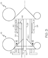
Figure 3 is a detailed partial cross-sectional drawing of the air cycle machine ofFigure 1 ; -
Figure 4 is a cross-sectional view of air cycle machine ofFigure 3 taken along the lines 4-4; and -
Figure 5 is a flow chart describing a method for cooling bearings in a turbomachine. - The following detailed description is of the best currently contemplated modes of carrying out exemplary embodiments of the invention. The description is not to be taken in a limiting sense, but is made merely for the purpose of illustrating the general principles of the invention, since the scope of the invention is best defined by the appended claims.
- Various inventive features are described below that can each be used independently of one another or in combination with other features.
- As used herein, the term "flexible", as it refers to a flexible link, is a relative term referring to a link connecting two shafts, wherein the flexible link may have a greater propensity for bending than the shaft itself. A "flexible link" may be flexible enough to lower a bending critical speed below the operating speed of a rotating machine.
- Referring to
Figure 1 , there is shown a cross-sectional drawing of a portion of an air cycle machine orturbomachine 10 according to an exemplary embodiment of the present invention. Theturbomachine 10 may include, as rotating components, afan 12, acompressor 14 and first andsecond turbines turbomachine 10 includes bearings, such asjournal bearings thrust bearings 30. The rotating components are mounted on ashaft assembly 26. At least a portion of theshaft assembly 26 may include aflexible link 28. Theshaft assembly 26 is held together with atie rod 29. According to one embodiment of the present invention, as shown inFigure 1 , theflexible link 28 may be positioned between thefan 12 and thecompressor 14. - Referring now to
Figure 2 , there is shown a pattern of cooling gas flow passageways which may carry cooling gas from theturbine 16 to the thrust bearings 30 (SeeFigure 1 ) and thejournal bearings turbineexit passageway 32 may be interconnected with bearing-input passageways passageway 36 may be interconnected with abearing chamber 38 which may carry cooling gas to the journal bearing 20. Thepassageway 34 may be interconnected withbearing chamber 40 which may carry cooling gas to the journal bearing 22 and twothrust bearings 30 adjacent thebearing 22. - The
bearing chamber 40 is interconnected with atransitional passageway 42 which carries cooling gas into an axially-oriented, cooling-gas passageway 44. A secondtransitional passageway 46 interconnects thepassageway 44 with a bearing chamber 48 within which cooling gas cools the journal bearing 24. - Referring now to
Figures 3 and4 , it may be seen thepassageway 44 passes axially along an interior of theshaft assembly 26. In that regard, thepassageway 44 passes through one or more aerodynamic components of themachine 10. In the exemplary configuration ofFigures 2 and3 , the aerodynamic component through whichpassageway 44 passes is the wheel 16-1 of theturbine 16. In alternate configurations, a cooling gas passageway passes through other ones of the aerodynamic components of themachine 10, e.g., impellers 14-1 or 12-1 of thecompressor 14 orfan 12. - Referring particularly to
Figure 4 , it may be seen thepassageway 44 includes one or more sub-passageways. The sub-passageways aregrooves 52 formed at an interface between the turbine wheel 16-1 and a portion of theshaft assembly 26. In an exemplary embodiment thegrooves 52 are formed in the turbine wheel 16-1. Advantageously such an arrangement allows for an enlargedportion 50 of thetie rod 29 to be tightly engageable with the wheel 16-1, thus providing desirable dynamic stability for theshaft assembly 26. In other words, cooling gas flows past the wheel 16-1 even though the wheel 16-1 is tightly engaged with the enlargedportion 50 of thetie rod 29. - In an exemplary embodiment of the
turbomachine 10, the cooling gas may be air. In this respect, theturbomachine 10 may differ from machines that may utilize gaseous refrigerant as a cooling gas. Cooling bearings with air as compared to refrigerant may require a higher volumetric flow rate of air as compared to that of refrigerant because the density of air is lower than that of gaseous refrigerant at an equivalent pressure. Thegrooves 52 in the wheel 16-1 may be made large enough to accommodate a required amount of gas flow that may be needed to fully cool thebearings 24 even though the cooling gas may be air and not gaseous refrigerant. In an exemplary embodiment, sufficient gas flow may be attained with three of thegrooves 52 that may be semicircular in cross-section with a radius of about 0.635 cm to about 1.27 cm (0.25 inch to about 0.50 inch). - Referring now to
Figure 5 , aflow chart 500 may illustrate an exemplary embodiment of a method for cooling bearings in a turbomachine. In astep 502, cooling gas may be extracted from a turbine (e.g., air may be extracted from theturbine 16 and directed into the passageway 34). In astep 504, the cooling gas may be passed in a first bearing chamber (e.g., the cooling gas may emerge from thepassageway 34 into the bearing chamber 40). In astep 506, the cooling gas may be passed to a second bearing chamber through grooves in a wheel or impeller (e.g., the cooling gas may emerge from the bearingchamber 40, enter atransitional passageway 42, pass throughgrooves 52 formed in the wheel 16-1 of theturbine 16 and then enter the bearing chamber 48). - It should be understood, of course, that the foregoing relates to exemplary embodiments of the invention and that modifications may be made without departing from the scope of the invention as set forth in the following claims.
Claims (5)
- A turbomachine (10) having gas cooled bearings (20, 22, 24 and 30) comprising an axially-oriented, cooling-gas passageway (44) interconnecting first and second bearing chambers (40, 48), the cooling-gas passageway (44) passing axially along an interior of a shaft assembly (26), characterized in that:the cooling-gas passageway (44) includes one or more grooves (52) formed at an interface between a wheel (16-1) of a turbine (16) or an impeller (12-1, 14-1) of the turbomachine and a portion of the shaft assembly (26) of the turbomachine; andthe one or more grooves allow the cooling gas to flow past the wheel (16-1) of the turbine (16) or the impeller (12-1, 14-1) wherein the wheel (16-1) of the turbine (16) or the impeller (12-1, 14-1) is tightly engaged with an enlarged portion (50) of a tie rod (29) of the shaft assembly.
- The turbomachine of claim 1 wherein the grooves (52) are semicircular in cross-sectional shape.
- The turbomachine of claim 1 wherein the shaft assembly (26) is supported on more than two journal bearings.
- The turbomachine of claim 1 wherein the shaft assembly (26) has a bending critical speed within the operating speed of the turbomachine.
- The turbomachine of claim 1 wherein the shaft assembly (26) includes a flexible link (28).
Applications Claiming Priority (1)
| Application Number | Priority Date | Filing Date | Title |
|---|---|---|---|
| US13/439,663 US9057283B2 (en) | 2012-04-04 | 2012-04-04 | Bearing cooling system for flexible shaft turbomachine |
Publications (3)
| Publication Number | Publication Date |
|---|---|
| EP2647801A2 EP2647801A2 (en) | 2013-10-09 |
| EP2647801A3 EP2647801A3 (en) | 2018-02-21 |
| EP2647801B1 true EP2647801B1 (en) | 2019-05-08 |
Family
ID=47998186
Family Applications (1)
| Application Number | Title | Priority Date | Filing Date |
|---|---|---|---|
| EP13159987.0A Active EP2647801B1 (en) | 2012-04-04 | 2013-03-19 | Bearing cooling system for flexible shaft turbomachine |
Country Status (2)
| Country | Link |
|---|---|
| US (1) | US9057283B2 (en) |
| EP (1) | EP2647801B1 (en) |
Cited By (2)
| Publication number | Priority date | Publication date | Assignee | Title |
|---|---|---|---|---|
| US11346249B2 (en) | 2019-03-05 | 2022-05-31 | Pratt & Whitney Canada Corp. | Gas turbine engine with feed pipe for bearing housing |
| US11391179B2 (en) | 2019-02-12 | 2022-07-19 | Pratt & Whitney Canada Corp. | Gas turbine engine with bearing support structure |
Families Citing this family (1)
| Publication number | Priority date | Publication date | Assignee | Title |
|---|---|---|---|---|
| US12504016B2 (en) | 2024-02-01 | 2025-12-23 | Hamilton Sundstrand Corporation | Bearing cooling flow path for a cabin air compressor |
Family Cites Families (7)
| Publication number | Priority date | Publication date | Assignee | Title |
|---|---|---|---|---|
| US5113670A (en) * | 1990-08-03 | 1992-05-19 | United Technologies Corporation | Bearing cooling arrangement for air cycle machine |
| US5249934A (en) * | 1992-01-10 | 1993-10-05 | United Technologies Corporation | Air cycle machine with heat isolation having back-to-back turbine and compressor rotors |
| GB9610018D0 (en) * | 1996-05-14 | 1996-07-17 | Rolls Royce Plc | Gas turbine engine turbine |
| JP2004245193A (en) * | 2003-02-17 | 2004-09-02 | Sumitomo Precision Prod Co Ltd | Air cycle air conditioner for aircraft |
| US7633193B2 (en) | 2007-01-17 | 2009-12-15 | Honeywell International Inc. | Thermal and secondary flow management of electrically driven compressors |
| US7948105B2 (en) | 2007-02-01 | 2011-05-24 | R&D Dynamics Corporation | Turboalternator with hydrodynamic bearings |
| US8376690B2 (en) | 2009-12-08 | 2013-02-19 | Honeywell International Inc. | Three bearing flexible shaft for high speed turbomachinery |
-
2012
- 2012-04-04 US US13/439,663 patent/US9057283B2/en active Active
-
2013
- 2013-03-19 EP EP13159987.0A patent/EP2647801B1/en active Active
Non-Patent Citations (1)
| Title |
|---|
| None * |
Cited By (2)
| Publication number | Priority date | Publication date | Assignee | Title |
|---|---|---|---|---|
| US11391179B2 (en) | 2019-02-12 | 2022-07-19 | Pratt & Whitney Canada Corp. | Gas turbine engine with bearing support structure |
| US11346249B2 (en) | 2019-03-05 | 2022-05-31 | Pratt & Whitney Canada Corp. | Gas turbine engine with feed pipe for bearing housing |
Also Published As
| Publication number | Publication date |
|---|---|
| US20130266417A1 (en) | 2013-10-10 |
| EP2647801A3 (en) | 2018-02-21 |
| EP2647801A2 (en) | 2013-10-09 |
| US9057283B2 (en) | 2015-06-16 |
Similar Documents
| Publication | Publication Date | Title |
|---|---|---|
| US9976485B2 (en) | Gas turbine engine buffer cooling system | |
| EP2809909B1 (en) | Gas turbine engine buffer system providing zoned ventilation | |
| US9157325B2 (en) | Buffer cooling system providing gas turbine engine architecture cooling | |
| EP2820271B1 (en) | Gas turbine engine buffer cooling system and method of cooling a gas turbine engine | |
| EP3073121B1 (en) | Bearing cooling flow and energy recovery systems | |
| US9145771B2 (en) | Rotor assembly disk spacer for a gas turbine engine | |
| EP2820253B1 (en) | Gas turbine | |
| EP2809919B1 (en) | Internally cooled spoke | |
| US8784048B2 (en) | Air cycle machine bearing cooling inlet plate | |
| US8376690B2 (en) | Three bearing flexible shaft for high speed turbomachinery | |
| US9745858B2 (en) | Air cycle machine turbine seal plate | |
| JP6773404B2 (en) | Compressor rotor, gas turbine rotor equipped with it, and gas turbine | |
| US9057283B2 (en) | Bearing cooling system for flexible shaft turbomachine | |
| US9651091B2 (en) | Thrust plate assembly | |
| JP2004245193A (en) | Air cycle air conditioner for aircraft | |
| US20170102002A1 (en) | Fan shaft for air cycle machine | |
| US20250341345A1 (en) | Multi-stage rotor for air cycle machine |
Legal Events
| Date | Code | Title | Description |
|---|---|---|---|
| PUAI | Public reference made under article 153(3) epc to a published international application that has entered the european phase |
Free format text: ORIGINAL CODE: 0009012 |
|
| 17P | Request for examination filed |
Effective date: 20130319 |
|
| AK | Designated contracting states |
Kind code of ref document: A2 Designated state(s): AL AT BE BG CH CY CZ DE DK EE ES FI FR GB GR HR HU IE IS IT LI LT LU LV MC MK MT NL NO PL PT RO RS SE SI SK SM TR |
|
| AX | Request for extension of the european patent |
Extension state: BA ME |
|
| RAP1 | Party data changed (applicant data changed or rights of an application transferred) |
Owner name: HONEYWELL INTERNATIONAL INC. |
|
| PUAL | Search report despatched |
Free format text: ORIGINAL CODE: 0009013 |
|
| AK | Designated contracting states |
Kind code of ref document: A3 Designated state(s): AL AT BE BG CH CY CZ DE DK EE ES FI FR GB GR HR HU IE IS IT LI LT LU LV MC MK MT NL NO PL PT RO RS SE SI SK SM TR |
|
| AX | Request for extension of the european patent |
Extension state: BA ME |
|
| RIC1 | Information provided on ipc code assigned before grant |
Ipc: F01D 25/12 20060101AFI20180116BHEP Ipc: F01D 25/16 20060101ALI20180116BHEP Ipc: F02C 7/06 20060101ALI20180116BHEP |
|
| STAA | Information on the status of an ep patent application or granted ep patent |
Free format text: STATUS: EXAMINATION IS IN PROGRESS |
|
| 17Q | First examination report despatched |
Effective date: 20180319 |
|
| GRAP | Despatch of communication of intention to grant a patent |
Free format text: ORIGINAL CODE: EPIDOSNIGR1 |
|
| STAA | Information on the status of an ep patent application or granted ep patent |
Free format text: STATUS: GRANT OF PATENT IS INTENDED |
|
| INTG | Intention to grant announced |
Effective date: 20181112 |
|
| GRAS | Grant fee paid |
Free format text: ORIGINAL CODE: EPIDOSNIGR3 |
|
| GRAA | (expected) grant |
Free format text: ORIGINAL CODE: 0009210 |
|
| STAA | Information on the status of an ep patent application or granted ep patent |
Free format text: STATUS: THE PATENT HAS BEEN GRANTED |
|
| AK | Designated contracting states |
Kind code of ref document: B1 Designated state(s): AL AT BE BG CH CY CZ DE DK EE ES FI FR GB GR HR HU IE IS IT LI LT LU LV MC MK MT NL NO PL PT RO RS SE SI SK SM TR |
|
| REG | Reference to a national code |
Ref country code: GB Ref legal event code: FG4D |
|
| REG | Reference to a national code |
Ref country code: CH Ref legal event code: EP Ref country code: AT Ref legal event code: REF Ref document number: 1130423 Country of ref document: AT Kind code of ref document: T Effective date: 20190515 |
|
| REG | Reference to a national code |
Ref country code: DE Ref legal event code: R096 Ref document number: 602013054900 Country of ref document: DE Ref country code: IE Ref legal event code: FG4D |
|
| REG | Reference to a national code |
Ref country code: NL Ref legal event code: MP Effective date: 20190508 |
|
| REG | Reference to a national code |
Ref country code: LT Ref legal event code: MG4D |
|
| PG25 | Lapsed in a contracting state [announced via postgrant information from national office to epo] |
Ref country code: HR Free format text: LAPSE BECAUSE OF FAILURE TO SUBMIT A TRANSLATION OF THE DESCRIPTION OR TO PAY THE FEE WITHIN THE PRESCRIBED TIME-LIMIT Effective date: 20190508 Ref country code: LT Free format text: LAPSE BECAUSE OF FAILURE TO SUBMIT A TRANSLATION OF THE DESCRIPTION OR TO PAY THE FEE WITHIN THE PRESCRIBED TIME-LIMIT Effective date: 20190508 Ref country code: NO Free format text: LAPSE BECAUSE OF FAILURE TO SUBMIT A TRANSLATION OF THE DESCRIPTION OR TO PAY THE FEE WITHIN THE PRESCRIBED TIME-LIMIT Effective date: 20190808 Ref country code: NL Free format text: LAPSE BECAUSE OF FAILURE TO SUBMIT A TRANSLATION OF THE DESCRIPTION OR TO PAY THE FEE WITHIN THE PRESCRIBED TIME-LIMIT Effective date: 20190508 Ref country code: SE Free format text: LAPSE BECAUSE OF FAILURE TO SUBMIT A TRANSLATION OF THE DESCRIPTION OR TO PAY THE FEE WITHIN THE PRESCRIBED TIME-LIMIT Effective date: 20190508 Ref country code: ES Free format text: LAPSE BECAUSE OF FAILURE TO SUBMIT A TRANSLATION OF THE DESCRIPTION OR TO PAY THE FEE WITHIN THE PRESCRIBED TIME-LIMIT Effective date: 20190508 Ref country code: AL Free format text: LAPSE BECAUSE OF FAILURE TO SUBMIT A TRANSLATION OF THE DESCRIPTION OR TO PAY THE FEE WITHIN THE PRESCRIBED TIME-LIMIT Effective date: 20190508 Ref country code: PT Free format text: LAPSE BECAUSE OF FAILURE TO SUBMIT A TRANSLATION OF THE DESCRIPTION OR TO PAY THE FEE WITHIN THE PRESCRIBED TIME-LIMIT Effective date: 20190908 Ref country code: FI Free format text: LAPSE BECAUSE OF FAILURE TO SUBMIT A TRANSLATION OF THE DESCRIPTION OR TO PAY THE FEE WITHIN THE PRESCRIBED TIME-LIMIT Effective date: 20190508 |
|
| PG25 | Lapsed in a contracting state [announced via postgrant information from national office to epo] |
Ref country code: BG Free format text: LAPSE BECAUSE OF FAILURE TO SUBMIT A TRANSLATION OF THE DESCRIPTION OR TO PAY THE FEE WITHIN THE PRESCRIBED TIME-LIMIT Effective date: 20190808 Ref country code: GR Free format text: LAPSE BECAUSE OF FAILURE TO SUBMIT A TRANSLATION OF THE DESCRIPTION OR TO PAY THE FEE WITHIN THE PRESCRIBED TIME-LIMIT Effective date: 20190809 Ref country code: LV Free format text: LAPSE BECAUSE OF FAILURE TO SUBMIT A TRANSLATION OF THE DESCRIPTION OR TO PAY THE FEE WITHIN THE PRESCRIBED TIME-LIMIT Effective date: 20190508 Ref country code: RS Free format text: LAPSE BECAUSE OF FAILURE TO SUBMIT A TRANSLATION OF THE DESCRIPTION OR TO PAY THE FEE WITHIN THE PRESCRIBED TIME-LIMIT Effective date: 20190508 |
|
| REG | Reference to a national code |
Ref country code: AT Ref legal event code: MK05 Ref document number: 1130423 Country of ref document: AT Kind code of ref document: T Effective date: 20190508 |
|
| PG25 | Lapsed in a contracting state [announced via postgrant information from national office to epo] |
Ref country code: SK Free format text: LAPSE BECAUSE OF FAILURE TO SUBMIT A TRANSLATION OF THE DESCRIPTION OR TO PAY THE FEE WITHIN THE PRESCRIBED TIME-LIMIT Effective date: 20190508 Ref country code: AT Free format text: LAPSE BECAUSE OF FAILURE TO SUBMIT A TRANSLATION OF THE DESCRIPTION OR TO PAY THE FEE WITHIN THE PRESCRIBED TIME-LIMIT Effective date: 20190508 Ref country code: DK Free format text: LAPSE BECAUSE OF FAILURE TO SUBMIT A TRANSLATION OF THE DESCRIPTION OR TO PAY THE FEE WITHIN THE PRESCRIBED TIME-LIMIT Effective date: 20190508 Ref country code: CZ Free format text: LAPSE BECAUSE OF FAILURE TO SUBMIT A TRANSLATION OF THE DESCRIPTION OR TO PAY THE FEE WITHIN THE PRESCRIBED TIME-LIMIT Effective date: 20190508 Ref country code: RO Free format text: LAPSE BECAUSE OF FAILURE TO SUBMIT A TRANSLATION OF THE DESCRIPTION OR TO PAY THE FEE WITHIN THE PRESCRIBED TIME-LIMIT Effective date: 20190508 Ref country code: EE Free format text: LAPSE BECAUSE OF FAILURE TO SUBMIT A TRANSLATION OF THE DESCRIPTION OR TO PAY THE FEE WITHIN THE PRESCRIBED TIME-LIMIT Effective date: 20190508 |
|
| REG | Reference to a national code |
Ref country code: DE Ref legal event code: R097 Ref document number: 602013054900 Country of ref document: DE |
|
| PG25 | Lapsed in a contracting state [announced via postgrant information from national office to epo] |
Ref country code: SM Free format text: LAPSE BECAUSE OF FAILURE TO SUBMIT A TRANSLATION OF THE DESCRIPTION OR TO PAY THE FEE WITHIN THE PRESCRIBED TIME-LIMIT Effective date: 20190508 Ref country code: IT Free format text: LAPSE BECAUSE OF FAILURE TO SUBMIT A TRANSLATION OF THE DESCRIPTION OR TO PAY THE FEE WITHIN THE PRESCRIBED TIME-LIMIT Effective date: 20190508 |
|
| PLBE | No opposition filed within time limit |
Free format text: ORIGINAL CODE: 0009261 |
|
| STAA | Information on the status of an ep patent application or granted ep patent |
Free format text: STATUS: NO OPPOSITION FILED WITHIN TIME LIMIT |
|
| PG25 | Lapsed in a contracting state [announced via postgrant information from national office to epo] |
Ref country code: TR Free format text: LAPSE BECAUSE OF FAILURE TO SUBMIT A TRANSLATION OF THE DESCRIPTION OR TO PAY THE FEE WITHIN THE PRESCRIBED TIME-LIMIT Effective date: 20190508 |
|
| 26N | No opposition filed |
Effective date: 20200211 |
|
| PG25 | Lapsed in a contracting state [announced via postgrant information from national office to epo] |
Ref country code: PL Free format text: LAPSE BECAUSE OF FAILURE TO SUBMIT A TRANSLATION OF THE DESCRIPTION OR TO PAY THE FEE WITHIN THE PRESCRIBED TIME-LIMIT Effective date: 20190508 |
|
| PG25 | Lapsed in a contracting state [announced via postgrant information from national office to epo] |
Ref country code: SI Free format text: LAPSE BECAUSE OF FAILURE TO SUBMIT A TRANSLATION OF THE DESCRIPTION OR TO PAY THE FEE WITHIN THE PRESCRIBED TIME-LIMIT Effective date: 20190508 |
|
| PG25 | Lapsed in a contracting state [announced via postgrant information from national office to epo] |
Ref country code: MC Free format text: LAPSE BECAUSE OF FAILURE TO SUBMIT A TRANSLATION OF THE DESCRIPTION OR TO PAY THE FEE WITHIN THE PRESCRIBED TIME-LIMIT Effective date: 20190508 |
|
| REG | Reference to a national code |
Ref country code: CH Ref legal event code: PL |
|
| REG | Reference to a national code |
Ref country code: BE Ref legal event code: MM Effective date: 20200331 |
|
| PG25 | Lapsed in a contracting state [announced via postgrant information from national office to epo] |
Ref country code: LU Free format text: LAPSE BECAUSE OF NON-PAYMENT OF DUE FEES Effective date: 20200319 |
|
| PG25 | Lapsed in a contracting state [announced via postgrant information from national office to epo] |
Ref country code: CH Free format text: LAPSE BECAUSE OF NON-PAYMENT OF DUE FEES Effective date: 20200331 Ref country code: IE Free format text: LAPSE BECAUSE OF NON-PAYMENT OF DUE FEES Effective date: 20200319 Ref country code: FR Free format text: LAPSE BECAUSE OF NON-PAYMENT OF DUE FEES Effective date: 20200331 Ref country code: LI Free format text: LAPSE BECAUSE OF NON-PAYMENT OF DUE FEES Effective date: 20200331 |
|
| PG25 | Lapsed in a contracting state [announced via postgrant information from national office to epo] |
Ref country code: BE Free format text: LAPSE BECAUSE OF NON-PAYMENT OF DUE FEES Effective date: 20200331 |
|
| PG25 | Lapsed in a contracting state [announced via postgrant information from national office to epo] |
Ref country code: MT Free format text: LAPSE BECAUSE OF FAILURE TO SUBMIT A TRANSLATION OF THE DESCRIPTION OR TO PAY THE FEE WITHIN THE PRESCRIBED TIME-LIMIT Effective date: 20190508 Ref country code: CY Free format text: LAPSE BECAUSE OF FAILURE TO SUBMIT A TRANSLATION OF THE DESCRIPTION OR TO PAY THE FEE WITHIN THE PRESCRIBED TIME-LIMIT Effective date: 20190508 |
|
| PG25 | Lapsed in a contracting state [announced via postgrant information from national office to epo] |
Ref country code: MK Free format text: LAPSE BECAUSE OF FAILURE TO SUBMIT A TRANSLATION OF THE DESCRIPTION OR TO PAY THE FEE WITHIN THE PRESCRIBED TIME-LIMIT Effective date: 20190508 Ref country code: IS Free format text: LAPSE BECAUSE OF FAILURE TO SUBMIT A TRANSLATION OF THE DESCRIPTION OR TO PAY THE FEE WITHIN THE PRESCRIBED TIME-LIMIT Effective date: 20190908 |
|
| P01 | Opt-out of the competence of the unified patent court (upc) registered |
Effective date: 20230525 |
|
| PGFP | Annual fee paid to national office [announced via postgrant information from national office to epo] |
Ref country code: GB Payment date: 20260319 Year of fee payment: 14 |
|
| PGFP | Annual fee paid to national office [announced via postgrant information from national office to epo] |
Ref country code: DE Payment date: 20260320 Year of fee payment: 14 |