EP2647797A2 - Vibration damping - Google Patents
Vibration damping Download PDFInfo
- Publication number
- EP2647797A2 EP2647797A2 EP13158922.8A EP13158922A EP2647797A2 EP 2647797 A2 EP2647797 A2 EP 2647797A2 EP 13158922 A EP13158922 A EP 13158922A EP 2647797 A2 EP2647797 A2 EP 2647797A2
- Authority
- EP
- European Patent Office
- Prior art keywords
- vibration damping
- cell
- insert
- damping insert
- cellular structure
- Prior art date
- Legal status (The legal status is an assumption and is not a legal conclusion. Google has not performed a legal analysis and makes no representation as to the accuracy of the status listed.)
- Withdrawn
Links
Images


Classifications
-
- F—MECHANICAL ENGINEERING; LIGHTING; HEATING; WEAPONS; BLASTING
- F16—ENGINEERING ELEMENTS AND UNITS; GENERAL MEASURES FOR PRODUCING AND MAINTAINING EFFECTIVE FUNCTIONING OF MACHINES OR INSTALLATIONS; THERMAL INSULATION IN GENERAL
- F16F—SPRINGS; SHOCK-ABSORBERS; MEANS FOR DAMPING VIBRATION
- F16F7/00—Vibration-dampers; Shock-absorbers
-
- F—MECHANICAL ENGINEERING; LIGHTING; HEATING; WEAPONS; BLASTING
- F16—ENGINEERING ELEMENTS AND UNITS; GENERAL MEASURES FOR PRODUCING AND MAINTAINING EFFECTIVE FUNCTIONING OF MACHINES OR INSTALLATIONS; THERMAL INSULATION IN GENERAL
- F16F—SPRINGS; SHOCK-ABSORBERS; MEANS FOR DAMPING VIBRATION
- F16F3/00—Spring units consisting of several springs, e.g. for obtaining a desired spring characteristic
- F16F3/08—Spring units consisting of several springs, e.g. for obtaining a desired spring characteristic with springs made of a material having high internal friction, e.g. rubber
- F16F3/087—Units comprising several springs made of plastics or the like material
- F16F3/093—Units comprising several springs made of plastics or the like material the springs being of different materials, e.g. having different types of rubber
-
- F—MECHANICAL ENGINEERING; LIGHTING; HEATING; WEAPONS; BLASTING
- F16—ENGINEERING ELEMENTS AND UNITS; GENERAL MEASURES FOR PRODUCING AND MAINTAINING EFFECTIVE FUNCTIONING OF MACHINES OR INSTALLATIONS; THERMAL INSULATION IN GENERAL
- F16F—SPRINGS; SHOCK-ABSORBERS; MEANS FOR DAMPING VIBRATION
- F16F2224/00—Materials; Material properties
- F16F2224/02—Materials; Material properties solids
- F16F2224/0225—Cellular, e.g. microcellular foam
-
- Y—GENERAL TAGGING OF NEW TECHNOLOGICAL DEVELOPMENTS; GENERAL TAGGING OF CROSS-SECTIONAL TECHNOLOGIES SPANNING OVER SEVERAL SECTIONS OF THE IPC; TECHNICAL SUBJECTS COVERED BY FORMER USPC CROSS-REFERENCE ART COLLECTIONS [XRACs] AND DIGESTS
- Y10—TECHNICAL SUBJECTS COVERED BY FORMER USPC
- Y10T—TECHNICAL SUBJECTS COVERED BY FORMER US CLASSIFICATION
- Y10T156/00—Adhesive bonding and miscellaneous chemical manufacture
- Y10T156/10—Methods of surface bonding and/or assembly therefor
Definitions
- the present invention relates to vibration damping structures and more particularly to vibration damping inserts for cellular materials which may be used, for example, as vibration damping materials within components or other structures comprising metals or composites.
- Cellular structures are used in a variety of engineering applications and conventional honeycomb cell structures have become widely used for their strength to weight characteristics. Examples of typical geometries of conventional cellular structures which have been used as cores in sandwich panels within, for example, the aerospace and marine industries are shown in Fig 1 .
- W02011/104112 discloses a cellular structure having either elastomer fillets at the vertices of cells or elastomer interlayers between the walls of adjacent cells to improve the vibration damping.
- a vibration damping insert configured to seat within a cell of a cellular structure and to span a cell cavity of the cell, the insert comprising: a first portion formed of a first material; and a second portion formed of a second material having lower stiffness than the first material; wherein the first portion is arranged to constrain deformation of the second portion to be in a predetermined direction.
- the second material provides vibration damping and the first material directs the effect to improve the vibration damping performance of the insert.
- Each cell may define a void therein, which may be gas filled, for example with air.
- the first material may comprise a polymer.
- the first material may comprise the material forming the cellular structure or may comprise a different material.
- the second material may comprise an elastomer, which may be a viscoelastic. The location of the second material can be chosen so that it is excited to a greater or lesser extent according to the vibration modes present in service. The second material has a higher intrinsic loss, and thus better damping, than the first material.
- the cellular structure may take the form of a so-called honeycomb structure.
- the predetermined direction may be aligned with a direction of shear stress or strain or with a direction of compression. There may be more than one predetermined direction.
- the first and second portions may form a shear-lap arrangement or a compression-lap arrangement.
- the cell may comprise a regular polygon; the cell may comprise a regular hexagon or a regular re-entrant polygon.
- the cell may be auxetic.
- the present invention also provides a vibration damping body comprising a cellular structure formed of a plurality of tessellating cells, the body further comprising a vibration damping insert as described above, the vibration damping insert being mounted in at least one of the cells in the cellular structure.
- the vibration damping body may be used as part or all of a component in a structure requiring vibration damped.
- the vibration damping body may comprise an aerofoil for a gas turbine engine, or may comprise the core thereof.
- the vibration damping insert may be mounted in each cell in the cellular structure or only in selected cells.
- the vibration damping insert in one cell may be aligned in a different direction to the vibration damping insert in another cell of the cellular structure.
- the present invention also provides a gas turbine engine comprising the vibration damping body described, and a gas turbine engine comprising the vibration damping insert described.
- the present invention also provides methods of manufacturing the vibration damping body comprising co-forming the cellular structure and the vibration damping insert; or bonding the vibration damping insert within a cell cavity of a cell of the cellular structure.
- the methods of manufacturing may also comprise moulding the first or second portions of the vibration damping insert.
- the present invention relates generally to insertion of a vibration damping insert into a cellular structure, such as an auxetic honeycomb, to assist in absorption of vibrational energy.
- a vibration damping insert into a cellular structure, such as an auxetic honeycomb.
- gas turbine engines such as gas turbine engines, industrial pumping equipment, power generation equipment and/or other types of propulsion equipment for use in aerospace, marine or land-based craft.
- a gas turbine engine 10 is shown in Figure 2 and comprises an air intake 12 and a propulsive fan 14 that generates two airflows A and B.
- the gas turbine engine 10 comprises, in axial flow A, an intermediate pressure compressor 16, a high pressure compressor 18, a combustor 20, a high pressure turbine 22, an intermediate pressure turbine 24, a low pressure turbine 26 and an exhaust nozzle 28.
- a nacelle 30 surrounds the gas turbine engine 10 and defines, in axial flow B, a bypass duct 32.
- the fan 14 comprises an array of fan blades 13.
- a cross-section of one of the fan blades 13 comprising a vibration damping body 34 according to one aspect of the present invention is shown in Figure 3 . It can be seen that opposing walls 36 and 38 of the fan blade 13 provide the gas washed surfaces in use and define there-between an internal cavity, in which the vibration damping body 34 is located.
- the rotation of the fan 14, compressors 16, 18 and turbines 22, 24, 26 within the engine 10 causes unwanted vibration. If unchecked, such vibrations can significantly reduce the performance of the engine 10 and the life of components therein. Accordingly the vibration damping body 34 is proposed to improve vibration damping properties of the blades 13.
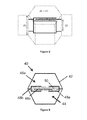
- the vibration damping body 34 comprises a cellular structure 35 which is formed of a plurality of tessellating cells 40, an embodiment of which is shown in Figure 4 .
- Each cell 40 is defined by cell walls 42 and defines a substantially air-filled cavity 44. Alternatively the cell cavity 44 may be filled or partially filled with a different fluid.
- each cell 40 is hexagonal. Alternatively, each cell 40 could be any regular polygon, such as octagonal or square.
- the cellular structure 35 has depth so that additional cell walls 42 extend perpendicularly to the plane of the polygon. Thus each cell 40 is a prism of constant cross section.
- Each cell 40 could alternatively have a regular re-entrant polygon shape, such as a regular re-entrant hexagon as shown in Figure 5 .
- a regular re-entrant shape allows for lateral expansion in tension and so is auxetic.
- An auxetic cell arrangement may also be described as 'dilational' or as having a negative Poisson's ratio. Poisson's ratio is defined as the negative of the transverse strain divided by the longitudinal strain. Accordingly, applying a unidirectional tensile force to auxetic material results in an increase in size in the transverse dimension.
- the vibration damping body 34 further comprises a vibration damping insert 46.
- the present invention also comprises a vibration damping insert 46 configured to seat within a cell 40 of a cellular structure 35 and to span the cell cavity 44.
- the vibration damping insert 46 is shown in Figure 6 and comprises two portions.
- the first portion 48 is formed of a first material and the second portion 50 is formed of a second material.
- the first portion 48 itself comprises a first part 48a and a second part 48b.
- the first portion 48 comprises more than two parts 48a, 48b as will be described below.
- the second material has a lower stiffness than the first material.
- the first material comprises a polymer and the second material comprises an elastomer such as silicone rubber, polybutadiene and/or natural rubber. More generally, an elastomer having a high intrinsic tangent loss coefficient may be used. It is found to be of benefit if a material displaying viscoelastic properties is used.
- the first material may be the same material as the cell walls 42 forming the cellular structure 35 of the vibration damping body 34.
- the key property of the second material is that it displays lower stiffness than that of the first material.
- the elastomer material in the honeycomb absorbs vibrational energy. This allows honeycombs to exhibit significantly larger vibration damping (or loss coefficients) for minimal weight penalties, more so than in existing competitor technologies.
- the vibration damping insert 46 is configured to span the cell cavity 44 and is initially described in two dimensions in the plane of the tessellating polygons.
- the first portion 48 seats within the cell 40 at two of the vertices of the cell 40.
- the vertices should be diametrically opposite, but the skilled reader will understand that a different pair of vertices may be chosen in other arrangements.
- the vibration damping insert 46 may be configured to seat against one or more cell walls 42 and be coupled thereto in a suitable manner.
- the first portion 48 of the vibration damping insert 46 is seated in diametrically opposed vertices of a hexagonal cell 40. Other cells 40 of the cellular structure 35 are not illustrated in this figure for clarity only.
- the vibration damping insert 46 takes the form of a so-called shear-lap insert 46a.
- the first part 48a of the first portion 48 extends from one of the cell vertices towards the other cell vertex and is straight.
- the second part 48b of the first portion 48 is U-shaped or cup-shaped with a rod part coupled between the closed end of the U-shape and the second cell vertex.
- the rod part is optional; instead the U-shaped part may be configured to abut the cell vertex directly.
- the second part 48b is arranged to surround the free end of the first part 48a so that the first portion 48 resembles a piston.
- the second part 48b does not touch the first part 48a in normal use.
- the second portion 50 of the vibration damping insert 46 is arranged to substantially fill the cavity within the U-shaped part of the second part 48b of the first portion 48.
- the first portion 48 acts to constrain the deformation of the second portion 50 to be in a predetermined direction which thereby improves the vibration damping capacity of the vibration damping insert 46.
- the maximum vibration damping is achieved when the vibration damping insert 46 is aligned with the principal direction of the stress or strain experienced by the cell 40.
- the vibration damping insert 46 is aligned with a direction of shear stress or strain applied to the cell 40 which is horizontally across the page as illustrated by shear stress or strain arrows 52.
- vibration damping insert 46 In applications where the cell 40 is subject to a different type of strain, for example compression strain, a different arrangement of vibration damping insert 46 is required. Similarly, if the cell 40 is subjected to strains in more than one direction a different arrangement of vibration damping insert 46 is more effective. Various alternative embodiments of vibration damping insert 46 will now be described.
- FIG. 7 shows an alternative arrangement of the vibration damping insert 46 of the present invention, a so-called compression-lap insert 46b, which is configured to effectively damp compression strains.
- the compression strain is applied to the cell 40 horizontally across the page as illustrated by compression strain arrows 54.
- the vibration damping insert 46 comprises the first portion 48 and the second portion 50 as in the shear-lap insert 46a.
- the first portion comprises first and second parts 48a, 48b which are mirror images of each other.
- Each of the first and second parts 48a, 48b comprises a first rod extending from one vertex of the cell 40 towards the other vertex and a second rod arranged perpendicularly thereto and coupled at its centre to the free end of the first rod to form a T-shape.
- the second rods of the first and second parts 48a, 48b are parallel to each other and spaced apart.
- the second portion 50 of the vibration damping insert 46 is arranged between the second rods of the first portion 48 so that its deformation is constrained by the first
- the vibration damping insert 46 In order to effectively damp in-plane vibration strains it is beneficial for the vibration damping insert 46 to extend with constant cross-sectional shape for the full depth of the cell 40. To damp out of plane vibration strains it may be more beneficial for the vibration damping insert 46 to extend over less than the full depth of the cell 40. In particular, for out of plane shear strains the shear-lap insert 46a may be configured such that it has a smaller depth than the cell walls 42. The shear-lap insert 46a may be centred vertically. This is illustrated in Figure 8 .
- first part 48a of the first portion 48 may extend from the base of the cell vertex upwards and the second part 48b of the first portion 48 may extend from the top of the opposite cell vertex downwards, with the second portion 50 filling the cavity of the second part 48b.
- FIG. 9 to 12 Further embodiments of the vibration damping insert 46 of the present invention are shown in Figures 9 to 12 .
- the first portions 48 comprise more than two parts.
- shear-lap inserts 46a are illustrated which are symmetrical in one or more plane perpendicular to the plane of the hexagon.
- Figures 9 and 10 each illustrate shear-lap inserts 46a with an additional degree of symmetry relative to the embodiment illustrated in Figure 6 ; that is they are each symmetric about a plane forming the locus between the vertices from which the first portion 48 of the vibration damping insert 46 extends.
- Figures 11 and 12 each illustrate shear-lap inserts 46a with two additional degrees of symmetry relative to the embodiments illustrated in Figures 9 and 10 ; that is they are each symmetric about every plane forming a locus between opposed vertices of the cell 40 and comprise multiple first portions 48 of the vibration damping insert 46 extending from each vertex.
- These vibration damping inserts 46a are multi-ended shear-lap inserts 46a.
- Each vibration damping insert 46 may be seated within an auxetic cell 40.
- a cell 40 may be a regular re-entrant polygon, such as a re-entrant hexagon. Any embodiment of the vibration damping insert 46 discussed above may be seated within the cell 40 to span the cell cavity 44 between opposed vertices or cell walls 42.
- a vibration damping body 34 comprises at least one vibration damping insert 46 mounted in a cell 40 of the cellular structure 35.
- the vibration damping body 34 may comprise additional components than the cellular structure 35 and one or more vibration damping inserts 46.
- the vibration damping inserts 46 mounted within cells 40 of the cellular structure 35 need not be aligned with each other. Thus strains in different directions may be damped by different vibration damping inserts 46 within a vibration damping body 34.
- the vibration damping body 34 may include skins or panels that close the planar faces of the cells 40.
- the vibration damping body 34 may be an aerofoil, such as a fan blade 13, having the cellular structure 35 spanning the internal cavity between the gas-washed surfaces of the aerofoil.
- Another aspect of the present invention comprises a gas turbine engine 10 comprising the vibration damping insert 46 as described in any of the embodiments.
- a further aspect comprises a gas turbine engine 10 comprising a vibration damping body 34 as described.
- the vibration damping body 34 may be formed by co-forming, for example by extrusion, the cellular structure 35 and the vibration damping insert 46.
- the vibration damping insert 46 may be formed by moulding.
- thermoplastic or thermoset cellular structure 35 may be made via standard commercial processes such as injection moulding or extrusion.
- the vibration damping insert 46 can be added into the cellular structure 46 via an additional step in either of these processes as will be understood by the skilled person using existing techniques.
- Such techniques may include so-called two-shot or multiple-shot injection moulding in which two or more different polymers are used to create a single conjoined structure in single or multiple moulding cycles.
- extrusion techniques a plurality of dyes may be used to produce the different material parts of the structure, such as by co-extrusion.
- the same techniques can be used for cellular structures 35 formed of metals and alloys.
- the vibration damping body 34 may be formed by bonding the vibration damping insert 46 within a cell 40 of the cellular structure 35. This is illustrated in the method steps of Figure 13 . Sheets of the first material are taken in step one and formed into the first and second parts 48a, 48b of the first portion 48 in step two. The second part 48b is filled with the second material to form the second portion in step three and then the first part 48a of the first portion 48 inserted into the second portion 50 in step four. This assembly is then cut into suitable lengths to fit in the cells 40 at step five before being bonded or otherwise mounted into selected ones of the cells 40 of the cellular structure 35 in step six to form the vibration damping body 34. As is apparent, not all the vibration damping inserts 46 are mounted at the same angle at step six so that vibrations in more than one direction can be damped effectively.
- vibration damping inserts 46 can be strongly adhered to the cellular structure 35 using any of the above-proposed techniques, they may also be more robust than competing technologies.
- the vibration damping insert 46 can be applied to other shape cells 40 using either manual or robotic-controlled shot injections for the second material.
- vibration damping insert 46 Whilst specific shapes of cell 40 have been discussed and are a particular focus of the present invention, the present invention is applicable to cells 40 with a wide variety of different geometries including circular cells 40.
- the vibration damping benefit is realised most effectively where the vibration damping insert 46 is aligned to a direction of high strain energy dissipation (static and/or modal).
- the insertion of vibration damping inserts 46 in three-dimensional truss structures and/or foams would also provide desirable vibration damping properties.
- the vibration damping inserts 46 and vibration damping bodies 34 have significantly improved damping in comparison with polymer-only cellular structures 35.
- the shear-lap inserts 46a provide energy dissipation during dynamic loading by the shearing of the second portion 50 of the vibration damping insert 46.
- the compression-lap inserts 46b provide the energy dissipation mainly through the increased strain energy during deformation at the cell vertices.
- the location of the vibration damping inserts 46 is optimal when they constrain the second material forming the second portion 50 to experience the largest deformation or highest strain energy levels.
- the weight increase to vibration damping (energy absorption per unit mass) improvement can be optimised using known methods such as numerical modelling.
- the relative stiffness of the first and second materials, and of these materials relative to the material of the cell walls 42 where this is not the same as the first material, can be optimised to improve the vibration damping of the present invention.
- any application where cellular structures 35 with large void fractions would be amenable to the use of targeted vibration damping inserts 46 such as are described above, particularly in applications where vibrations are problematic, and/or where it is important to maintain low structural weight.
- the vibration damping insert 46 of the present invention reducing the empty space in the cell cavities 44, the void fraction of the cells 40 remains relatively high in comparison to a filled honeycomb or cellular structure 35.
- the present invention enables reduction of vibration in components, structures and assemblies.
- manufacturing is simplified if the cells 40 have constant cross-section, this is not required to obtain the advantages of the present invention.
- the vibration damping insert 46 and vibration damping body 34 of the present invention may be used in any application comprising a cellular structure in which it is desirable to damp vibrations.
- it finds utility in the aerofoils of a gas turbine engine, in a nacelle surrounding a gas turbine engine, in the pylon coupling a gas turbine engine to an aircraft, for aspects of an aircraft such as the panels, in power plants based on gas turbine engines, electrical, fossil fuels or nuclear power, and in general machinery which is subject to vibration.
Abstract
Description
- The present invention relates to vibration damping structures and more particularly to vibration damping inserts for cellular materials which may be used, for example, as vibration damping materials within components or other structures comprising metals or composites.
- Cellular structures are used in a variety of engineering applications and conventional honeycomb cell structures have become widely used for their strength to weight characteristics. Examples of typical geometries of conventional cellular structures which have been used as cores in sandwich panels within, for example, the aerospace and marine industries are shown in
Fig 1 . - Conventional materials for formation of the cell structure include aluminium, Nomex® (aramid), Kevlar ®, and other common thermoplastic polymers. Such structures can be considered to be 'monolithic' honeycombs since there is only one significant phase present, plus air.
- The primary function of materials chosen for use as sandwich panel cores is to maintain a separation between opposing skins. Such materials are generally relatively stiff and display low loss coefficients. The ability of these monolithic honeycombs to absorb vibration energy, is dependent primarily upon the constituent material's inherent damping or loss coefficient and not upon geometrical properties of the structure. Thus the ability of such structures to benefit the damping behaviour of the structure is limited.
- Furthermore, alternative materials which are known to have higher loss coefficients, and thus better damping, generally display lower stiffness characteristics and are unsuitable for use as structural components such as honeycomb cores. The unavoidable trade off between these two properties further compounds the above problem.
-
W02011/104112 discloses a cellular structure having either elastomer fillets at the vertices of cells or elastomer interlayers between the walls of adjacent cells to improve the vibration damping. - It is an aim of the present invention to provide a vibration damping insert configured for cellular structures offering improved vibration damping properties.
- According to a first aspect of the present invention there is provided a vibration damping insert configured to seat within a cell of a cellular structure and to span a cell cavity of the cell, the insert comprising: a first portion formed of a first material; and a second portion formed of a second material having lower stiffness than the first material; wherein the first portion is arranged to constrain deformation of the second portion to be in a predetermined direction.
- Advantageously, the second material provides vibration damping and the first material directs the effect to improve the vibration damping performance of the insert.
- Each cell may define a void therein, which may be gas filled, for example with air.
- The first material may comprise a polymer. The first material may comprise the material forming the cellular structure or may comprise a different material. The second material may comprise an elastomer, which may be a viscoelastic. The location of the second material can be chosen so that it is excited to a greater or lesser extent according to the vibration modes present in service. The second material has a higher intrinsic loss, and thus better damping, than the first material. The cellular structure may take the form of a so-called honeycomb structure.
- The predetermined direction may be aligned with a direction of shear stress or strain or with a direction of compression. There may be more than one predetermined direction.
- The first and second portions may form a shear-lap arrangement or a compression-lap arrangement.
- The cell may comprise a regular polygon; the cell may comprise a regular hexagon or a regular re-entrant polygon. The cell may be auxetic.
- The present invention also provides a vibration damping body comprising a cellular structure formed of a plurality of tessellating cells, the body further comprising a vibration damping insert as described above, the vibration damping insert being mounted in at least one of the cells in the cellular structure.
- Advantageously the vibration damping body may be used as part or all of a component in a structure requiring vibration damped. For example, the vibration damping body may comprise an aerofoil for a gas turbine engine, or may comprise the core thereof.
- The vibration damping insert may be mounted in each cell in the cellular structure or only in selected cells. The vibration damping insert in one cell may be aligned in a different direction to the vibration damping insert in another cell of the cellular structure.
- The present invention also provides a gas turbine engine comprising the vibration damping body described, and a gas turbine engine comprising the vibration damping insert described.
- The present invention also provides methods of manufacturing the vibration damping body comprising co-forming the cellular structure and the vibration damping insert; or bonding the vibration damping insert within a cell cavity of a cell of the cellular structure. The methods of manufacturing may also comprise moulding the first or second portions of the vibration damping insert.
- Embodiments of the present invention are described in further detail below by way of example with reference to the accompanying drawings, of which:
-
Figure 1 shows known cross-sections of cellular structures. -
Figure 2 is a sectional side view of a gas turbine engine in which the present invention may be used. -
Figure 3 shows a cross section of a blade comprising vibration damping according to the present invention. -
Figure 4 shows a hexagonal cellular structure forming a vibration damping body according to aspects of the present invention. -
Figure 5 shows a re-entrant hexagonal cellular structure forming a vibration damping body according to aspects of the present invention. -
Figure 6 shows a hexagonal cell with a vibration damping insert according to the present invention. -
Figure 7 shows a hexagonal cell with another vibration damping insert according to the present invention. -
Figure 8 shows a perspective view of a hexagonal with a vibration damping insert according to the present invention. -
Figures 9 to 12 show hexagonal cells with alternative vibration damping inserts according to the present invention. -
Figure 13 shows one method of manufacturing a vibration damping body according to the present invention. - The present invention relates generally to insertion of a vibration damping insert into a cellular structure, such as an auxetic honeycomb, to assist in absorption of vibrational energy. There are many industrial machinery applications in which the present invention may be advantageous, such as for example, gas turbine engines, industrial pumping equipment, power generation equipment and/or other types of propulsion equipment for use in aerospace, marine or land-based craft.
- Whilst the embodiments of the present invention described below focus on the use of vibration damping for blades, such as fan blades of a gas turbine engine, the skilled person will appreciate that the present invention may find application in any circumstances where conventional cellular materials have previously been proposed or adopted. It is to be noted that a majority of such applications currently under consideration involve provision of a cellular material as a filler between opposing walls of a larger component or structure.
- A
gas turbine engine 10 is shown inFigure 2 and comprises anair intake 12 and apropulsive fan 14 that generates two airflows A and B. Thegas turbine engine 10 comprises, in axial flow A, anintermediate pressure compressor 16, ahigh pressure compressor 18, acombustor 20, ahigh pressure turbine 22, anintermediate pressure turbine 24, alow pressure turbine 26 and anexhaust nozzle 28. Anacelle 30 surrounds thegas turbine engine 10 and defines, in axial flow B, abypass duct 32. - The
fan 14 comprises an array offan blades 13. A cross-section of one of thefan blades 13 comprising avibration damping body 34 according to one aspect of the present invention is shown inFigure 3 . It can be seen thatopposing walls fan blade 13 provide the gas washed surfaces in use and define there-between an internal cavity, in which thevibration damping body 34 is located. During operation, the rotation of thefan 14,compressors turbines engine 10 causes unwanted vibration. If unchecked, such vibrations can significantly reduce the performance of theengine 10 and the life of components therein. Accordingly thevibration damping body 34 is proposed to improve vibration damping properties of theblades 13. - The
vibration damping body 34 comprises acellular structure 35 which is formed of a plurality of tessellatingcells 40, an embodiment of which is shown inFigure 4 . Eachcell 40 is defined bycell walls 42 and defines a substantially air-filledcavity 44. Alternatively thecell cavity 44 may be filled or partially filled with a different fluid. In the illustrated embodiment, eachcell 40 is hexagonal. Alternatively, eachcell 40 could be any regular polygon, such as octagonal or square. Thecellular structure 35 has depth so thatadditional cell walls 42 extend perpendicularly to the plane of the polygon. Thus eachcell 40 is a prism of constant cross section. - Each
cell 40 could alternatively have a regular re-entrant polygon shape, such as a regular re-entrant hexagon as shown inFigure 5 . Such a re-entrant shape allows for lateral expansion in tension and so is auxetic. An auxetic cell arrangement may also be described as 'dilational' or as having a negative Poisson's ratio. Poisson's ratio is defined as the negative of the transverse strain divided by the longitudinal strain. Accordingly, applying a unidirectional tensile force to auxetic material results in an increase in size in the transverse dimension. - The
vibration damping body 34 further comprises a vibration damping insert 46. The present invention also comprises a vibration damping insert 46 configured to seat within acell 40 of acellular structure 35 and to span thecell cavity 44. - An embodiment of the vibration damping insert 46 is shown in
Figure 6 and comprises two portions. The first portion 48 is formed of a first material and thesecond portion 50 is formed of a second material. The first portion 48 itself comprises afirst part 48a and asecond part 48b. In other embodiments of the vibration damping insert 46 the first portion 48 comprises more than twoparts - In one application of the vibration damping insert 46 of the present invention the first material comprises a polymer and the second material comprises an elastomer such as silicone rubber, polybutadiene and/or natural rubber. More generally, an elastomer having a high intrinsic tangent loss coefficient may be used. It is found to be of benefit if a material displaying viscoelastic properties is used. The first material may be the same material as the
cell walls 42 forming thecellular structure 35 of thevibration damping body 34. The key property of the second material is that it displays lower stiffness than that of the first material. Thus the elastomer material in the honeycomb absorbs vibrational energy. This allows honeycombs to exhibit significantly larger vibration damping (or loss coefficients) for minimal weight penalties, more so than in existing competitor technologies. - The vibration damping insert 46 is configured to span the
cell cavity 44 and is initially described in two dimensions in the plane of the tessellating polygons. Preferably the first portion 48 seats within thecell 40 at two of the vertices of thecell 40. To effectively damp most vibration modes the vertices should be diametrically opposite, but the skilled reader will understand that a different pair of vertices may be chosen in other arrangements. Similarly, for somecell 40 shapes there may not be opposite vertices, in which case the vibration damping insert 46 may be configured to seat against one ormore cell walls 42 and be coupled thereto in a suitable manner. - In the embodiment illustrated in
Figure 6 the first portion 48 of the vibration damping insert 46 is seated in diametrically opposed vertices of ahexagonal cell 40.Other cells 40 of thecellular structure 35 are not illustrated in this figure for clarity only. The vibration damping insert 46 takes the form of a so-called shear-lap insert 46a. Thefirst part 48a of the first portion 48 extends from one of the cell vertices towards the other cell vertex and is straight. Thesecond part 48b of the first portion 48 is U-shaped or cup-shaped with a rod part coupled between the closed end of the U-shape and the second cell vertex. The rod part is optional; instead the U-shaped part may be configured to abut the cell vertex directly. Thesecond part 48b is arranged to surround the free end of thefirst part 48a so that the first portion 48 resembles a piston. Thesecond part 48b does not touch thefirst part 48a in normal use. - The
second portion 50 of the vibration damping insert 46 is arranged to substantially fill the cavity within the U-shaped part of thesecond part 48b of the first portion 48. When thecell 40 is subject to stress or strain thesecond portion 50 of the vibration damping insert 46 deforms more readily than the first portion 48 due to the different stiffnesses. The first portion 48 acts to constrain the deformation of thesecond portion 50 to be in a predetermined direction which thereby improves the vibration damping capacity of the vibration damping insert 46. The maximum vibration damping is achieved when the vibration damping insert 46 is aligned with the principal direction of the stress or strain experienced by thecell 40. Thus in the illustrated embodiment, the vibration damping insert 46 is aligned with a direction of shear stress or strain applied to thecell 40 which is horizontally across the page as illustrated by shear stress orstrain arrows 52. - In applications where the
cell 40 is subject to a different type of strain, for example compression strain, a different arrangement of vibration damping insert 46 is required. Similarly, if thecell 40 is subjected to strains in more than one direction a different arrangement of vibration damping insert 46 is more effective. Various alternative embodiments of vibration damping insert 46 will now be described. -
Figure 7 shows an alternative arrangement of the vibration damping insert 46 of the present invention, a so-called compression-lap insert 46b, which is configured to effectively damp compression strains. The compression strain is applied to thecell 40 horizontally across the page as illustrated bycompression strain arrows 54. The vibration damping insert 46 comprises the first portion 48 and thesecond portion 50 as in the shear-lap insert 46a. In the compression-lap insert 46b the first portion comprises first andsecond parts second parts cell 40 towards the other vertex and a second rod arranged perpendicularly thereto and coupled at its centre to the free end of the first rod to form a T-shape. The second rods of the first andsecond parts second portion 50 of the vibration damping insert 46 is arranged between the second rods of the first portion 48 so that its deformation is constrained by the first portion 48. - In order to effectively damp in-plane vibration strains it is beneficial for the vibration damping insert 46 to extend with constant cross-sectional shape for the full depth of the
cell 40. To damp out of plane vibration strains it may be more beneficial for the vibration damping insert 46 to extend over less than the full depth of thecell 40. In particular, for out of plane shear strains the shear-lap insert 46a may be configured such that it has a smaller depth than thecell walls 42. The shear-lap insert 46a may be centred vertically. This is illustrated inFigure 8 . Alternatively, thefirst part 48a of the first portion 48 may extend from the base of the cell vertex upwards and thesecond part 48b of the first portion 48 may extend from the top of the opposite cell vertex downwards, with thesecond portion 50 filling the cavity of thesecond part 48b. - Further embodiments of the vibration damping insert 46 of the present invention are shown in
Figures 9 to 12 . In these embodiments the first portions 48 comprise more than two parts. In particular further shear-lap inserts 46a are illustrated which are symmetrical in one or more plane perpendicular to the plane of the hexagon.Figures 9 and10 each illustrate shear-lap inserts 46a with an additional degree of symmetry relative to the embodiment illustrated inFigure 6 ; that is they are each symmetric about a plane forming the locus between the vertices from which the first portion 48 of the vibration damping insert 46 extends. -
Figures 11 and12 each illustrate shear-lap inserts 46a with two additional degrees of symmetry relative to the embodiments illustrated inFigures 9 and10 ; that is they are each symmetric about every plane forming a locus between opposed vertices of thecell 40 and comprise multiple first portions 48 of the vibration damping insert 46 extending from each vertex. Thesevibration damping inserts 46a are multi-ended shear-lap inserts 46a. - Beneficially there is a
permeable wall 56 of the first material forming the closed end of the U-shaped parts of the first portion 48 of the vibration damping insert 46 inFigure 10 andFigure 12 . This means that thesecond portion 50 can permeate from one cavity to another, or to several others, formed by the first portion 48 when the vibration damping insert 46 is subjected to the strain experienced by thecell 40. - Each vibration damping insert 46 may be seated within an
auxetic cell 40. Such acell 40 may be a regular re-entrant polygon, such as a re-entrant hexagon. Any embodiment of the vibration damping insert 46 discussed above may be seated within thecell 40 to span thecell cavity 44 between opposed vertices orcell walls 42. - A
vibration damping body 34 according to the present invention comprises at least one vibration damping insert 46 mounted in acell 40 of thecellular structure 35. In one example, there is a vibration damping insert 46 mounted in eachcell 40 of thecellular structure 35 to form thevibration damping body 34. In another example, there is a vibration damping insert 46 mounted in at least one but not all of thecells 40 forming thecellular structure 35. Thevibration damping body 34 may comprise additional components than thecellular structure 35 and one or more vibration damping inserts 46. The vibration damping inserts 46 mounted withincells 40 of thecellular structure 35 need not be aligned with each other. Thus strains in different directions may be damped by different vibration damping inserts 46 within avibration damping body 34. - The
vibration damping body 34 may include skins or panels that close the planar faces of thecells 40. For example, thevibration damping body 34 may be an aerofoil, such as afan blade 13, having thecellular structure 35 spanning the internal cavity between the gas-washed surfaces of the aerofoil. - Another aspect of the present invention comprises a
gas turbine engine 10 comprising the vibration damping insert 46 as described in any of the embodiments. A further aspect comprises agas turbine engine 10 comprising avibration damping body 34 as described. - There are various methods of manufacturing a
vibration damping body 34 according to the present invention. Thevibration damping body 34 may be formed by co-forming, for example by extrusion, thecellular structure 35 and the vibration damping insert 46. The vibration damping insert 46 may be formed by moulding. - The basic form of a thermoplastic or thermoset
cellular structure 35 may be made via standard commercial processes such as injection moulding or extrusion. The vibration damping insert 46 can be added into the cellular structure 46 via an additional step in either of these processes as will be understood by the skilled person using existing techniques. Such techniques may include so-called two-shot or multiple-shot injection moulding in which two or more different polymers are used to create a single conjoined structure in single or multiple moulding cycles. In extrusion techniques, a plurality of dyes may be used to produce the different material parts of the structure, such as by co-extrusion. The same techniques can be used forcellular structures 35 formed of metals and alloys. - Alternatively, the
vibration damping body 34 may be formed by bonding the vibration damping insert 46 within acell 40 of thecellular structure 35. This is illustrated in the method steps ofFigure 13 . Sheets of the first material are taken in step one and formed into the first andsecond parts second part 48b is filled with the second material to form the second portion in step three and then thefirst part 48a of the first portion 48 inserted into thesecond portion 50 in step four. This assembly is then cut into suitable lengths to fit in thecells 40 at step five before being bonded or otherwise mounted into selected ones of thecells 40 of thecellular structure 35 in step six to form thevibration damping body 34. As is apparent, not all the vibration damping inserts 46 are mounted at the same angle at step six so that vibrations in more than one direction can be damped effectively. - Since the vibration damping inserts 46 can be strongly adhered to the
cellular structure 35 using any of the above-proposed techniques, they may also be more robust than competing technologies. The vibration damping insert 46 can be applied toother shape cells 40 using either manual or robotic-controlled shot injections for the second material. - Whilst specific shapes of
cell 40 have been discussed and are a particular focus of the present invention, the present invention is applicable tocells 40 with a wide variety of different geometries includingcircular cells 40. The vibration damping benefit is realised most effectively where the vibration damping insert 46 is aligned to a direction of high strain energy dissipation (static and/or modal). Thus the insertion of vibration damping inserts 46 in three-dimensional truss structures and/or foams would also provide desirable vibration damping properties. - The vibration damping inserts 46 and
vibration damping bodies 34 have significantly improved damping in comparison with polymer-onlycellular structures 35. The shear-lap inserts 46a provide energy dissipation during dynamic loading by the shearing of thesecond portion 50 of the vibration damping insert 46. The compression-lap inserts 46b provide the energy dissipation mainly through the increased strain energy during deformation at the cell vertices. - The location of the vibration damping inserts 46 is optimal when they constrain the second material forming the
second portion 50 to experience the largest deformation or highest strain energy levels. The weight increase to vibration damping (energy absorption per unit mass) improvement can be optimised using known methods such as numerical modelling. Similarly the relative stiffness of the first and second materials, and of these materials relative to the material of thecell walls 42 where this is not the same as the first material, can be optimised to improve the vibration damping of the present invention. - Any application where
cellular structures 35 with large void fractions would be amenable to the use of targeted vibration damping inserts 46 such as are described above, particularly in applications where vibrations are problematic, and/or where it is important to maintain low structural weight. Despite the vibration damping insert 46 of the present invention reducing the empty space in thecell cavities 44, the void fraction of thecells 40 remains relatively high in comparison to a filled honeycomb orcellular structure 35. - Advantageously the present invention enables reduction of vibration in components, structures and assemblies. Although manufacturing is simplified if the
cells 40 have constant cross-section, this is not required to obtain the advantages of the present invention. - The vibration damping insert 46 and
vibration damping body 34 of the present invention may be used in any application comprising a cellular structure in which it is desirable to damp vibrations. For example, it finds utility in the aerofoils of a gas turbine engine, in a nacelle surrounding a gas turbine engine, in the pylon coupling a gas turbine engine to an aircraft, for aspects of an aircraft such as the panels, in power plants based on gas turbine engines, electrical, fossil fuels or nuclear power, and in general machinery which is subject to vibration.
Claims (15)
- A vibration damping insert (46) configured to seat within a cell (40) of a cellular structure (35) and to span a cell cavity (44) of the cell (40), the insert (46) comprising:a first portion (48) formed of a first material; anda second portion (50) formed of a second material having lower stiffness than the first material;
wherein the first portion (48) is arranged to constrain deformation of the second portion (50) to be in a predetermined direction. - A vibration damping insert (46) as claimed in claim 1 wherein the first material comprises a polymer and/or the second material comprising an elastomer.
- A vibration damping insert (46) as claimed in claim 2 wherein the second material comprises viscoelastic.
- A vibration damping insert (46) as claimed in any preceding claim wherein the first material comprises the material forming the cellular structure (35).
- A vibration damping insert (46) as claimed in any of claims 1 to 4 wherein the predetermined direction is aligned with a direction of: shear stress, strain or compression.
- A vibration damping insert (46) as claimed in any of claims 1 to 5 wherein the first and second portions (48, 50) form a shear-lap arrangement.
- A vibration damping insert (46) as claimed in claim 6 wherein the first and second portions (48, 50) form a multi-ended shear-lap arrangement.
- A vibration damping insert (46) as claimed in any of claims 1 to 5 wherein the first and second portions (48, 50) form a compression-lap arrangement.
- A vibration damping insert (46) as claimed in any preceding claim wherein the cell (40) comprises a regular polygon or a re-entrant regular polygon.
- A vibration damping insert (46) as claimed in claim 9 wherein the cell (40) is auxetic.
- A vibration damping body (34) comprising a cellular structure (35) formed of a plurality of tessellating cells (40), the body (34) further comprising a vibration damping insert (46) as claimed in any preceding claim, the vibration damping insert (46) being mounted in at least one of the cells (40) in the cellular structure (35).
- A vibration damping body (34) as claimed in claim 11 wherein a vibration damping insert (46) is mounted in each cell (40) in the cellular structure (35).
- A gas turbine engine (10) comprising a vibration damping body (34) as claimed in claim 11 or 12, wherein the body (34) comprises an aerofoil.
- A method of manufacturing a vibration damping body (34) as claimed in claim 11 or 12 comprising co-forming the cellular structure (35) and the vibration damping insert (46) or bonding the vibration damping insert (46) within a cell cavity (44) of a cell (40) of the cellular structure (35).
- A method of manufacturing a vibration damping body (34) as claimed in claim 11 or 12 comprising moulding the first or second portions (48, 50) of the vibration damping insert (46).
Applications Claiming Priority (1)
| Application Number | Priority Date | Filing Date | Title |
|---|---|---|---|
| GBGB1206025.7A GB201206025D0 (en) | 2012-04-04 | 2012-04-04 | Vibration damping |
Publications (2)
| Publication Number | Publication Date |
|---|---|
| EP2647797A2 true EP2647797A2 (en) | 2013-10-09 |
| EP2647797A3 EP2647797A3 (en) | 2018-01-24 |
Family
ID=46160313
Family Applications (1)
| Application Number | Title | Priority Date | Filing Date |
|---|---|---|---|
| EP13158922.8A Withdrawn EP2647797A3 (en) | 2012-04-04 | 2013-03-13 | Vibration damping |
Country Status (3)
| Country | Link |
|---|---|
| US (1) | US9494206B2 (en) |
| EP (1) | EP2647797A3 (en) |
| GB (1) | GB201206025D0 (en) |
Cited By (1)
| Publication number | Priority date | Publication date | Assignee | Title |
|---|---|---|---|---|
| CN106907418A (en) * | 2017-01-20 | 2017-06-30 | 上海交通大学 | Phonon crystal negative poisson's ratio honeycomb vibration isolation anti-impact device |
Families Citing this family (26)
| Publication number | Priority date | Publication date | Assignee | Title |
|---|---|---|---|---|
| US8539737B2 (en) | 2008-09-19 | 2013-09-24 | Ford Global Technologies, Llc | Twelve-cornered strengthening member |
| US10563538B2 (en) | 2013-10-23 | 2020-02-18 | United Technologies Corporation | Nanocellular foam damper |
| US20160281510A1 (en) * | 2013-11-14 | 2016-09-29 | General Electric Company | Turbine components with negative cte features |
| US10315698B2 (en) | 2015-06-24 | 2019-06-11 | Ford Global Technologies, Llc | Sixteen-cornered strengthening member for vehicles |
| ES2746478T3 (en) * | 2015-08-27 | 2020-03-06 | Airbus Operations Sl | Deformable structure for the absorption of energy from mechanical and / or acoustic impacts |
| DE102016206022A1 (en) * | 2016-04-12 | 2017-10-12 | Siemens Aktiengesellschaft | Seal for turbomachinery |
| US10393315B2 (en) | 2016-04-26 | 2019-08-27 | Ford Global Technologies, Llc | Cellular structures with twelve-cornered cells |
| US10704638B2 (en) | 2016-04-26 | 2020-07-07 | Ford Global Technologies, Llc | Cellular structures with twelve-cornered cells |
| US10473177B2 (en) * | 2016-08-23 | 2019-11-12 | Ford Global Technologies, Llc | Cellular structures with sixteen-cornered cells |
| US10220881B2 (en) | 2016-08-26 | 2019-03-05 | Ford Global Technologies, Llc | Cellular structures with fourteen-cornered cells |
| US10279842B2 (en) | 2016-08-30 | 2019-05-07 | Ford Global Technologies, Llc | Twenty-eight-cornered strengthening member for vehicles |
| US10300947B2 (en) | 2016-08-30 | 2019-05-28 | Ford Global Technologies, Llc | Twenty-eight-cornered strengthening member for vehicles |
| US10429006B2 (en) | 2016-10-12 | 2019-10-01 | Ford Global Technologies, Llc | Cellular structures with twelve-cornered cells |
| EP3339677B1 (en) * | 2016-12-20 | 2019-11-20 | Airbus Operations, S.L. | Energy absorbing structure for attenuating the energy transmitted from an energy source |
| TR201707444A2 (en) * | 2017-05-22 | 2017-07-21 | Univ Istanbul Teknik | MODULAR IMPACT DAMPING STRUCTURE |
| US11399593B2 (en) | 2017-05-25 | 2022-08-02 | Nike, Inc. | Article of footwear with auxetic sole structure having a filled auxetic aperture |
| DE102017122183A1 (en) | 2017-09-25 | 2019-03-28 | Brose Fahrzeugteile Gmbh & Co. Kg, Coburg | Geometry adjuster auxetic |
| US10808794B1 (en) * | 2018-03-19 | 2020-10-20 | National Technology & Engineering Solutions Of Sandia, Llc | Topological damping materials and methods thereof |
| US11292522B2 (en) | 2019-12-04 | 2022-04-05 | Ford Global Technologies, Llc | Splayed front horns for vehicle frames |
| US11739645B2 (en) * | 2020-09-30 | 2023-08-29 | General Electric Company | Vibrational dampening elements |
| CN112665460A (en) * | 2020-12-22 | 2021-04-16 | 北京理工大学 | Indent honeycomb type explosion-proof construction |
| US20220381315A1 (en) * | 2021-05-27 | 2022-12-01 | Northeastern University | Three-dimensional auxetic composite structures |
| CN114001115B (en) * | 2021-10-29 | 2022-12-09 | 西安交通大学 | Gradient vibration reduction structure and vibration reduction method based on mechanical-electrical conversion |
| CN114396447B (en) * | 2022-01-25 | 2023-07-21 | 广州大学 | Vibration reduction structure with zero poisson ratio characteristic |
| US20230366960A1 (en) * | 2022-05-12 | 2023-11-16 | Joon Bu Park | Negative poisson's ratio materials for energy absorption |
| US11608158B1 (en) * | 2022-07-25 | 2023-03-21 | Joon Bu Park | Negative Poisson's ratio materials for propellers and turbines |
Family Cites Families (29)
| Publication number | Priority date | Publication date | Assignee | Title |
|---|---|---|---|---|
| DE2447565C3 (en) * | 1974-10-05 | 1978-07-20 | Messerschmitt-Boelkow-Blohm Gmbh, 8000 Muenchen | Fine metal mesh structure with arched lattice bars |
| US4786343A (en) | 1985-05-10 | 1988-11-22 | The Boeing Company | Method of making delamination resistant composites |
| US4899323A (en) * | 1986-08-04 | 1990-02-06 | Bridgestone Corporation | Anti-seismic device |
| US5915508A (en) * | 1994-04-18 | 1999-06-29 | Minnesota Mining And Manufacturing Company | Tuned mass damper |
| US5862975A (en) | 1996-03-20 | 1999-01-26 | The Boeing Company | Composite/metal structural joint with welded Z-pins |
| FR2781719B1 (en) * | 1998-07-30 | 2000-09-08 | Hispano Suiza Sa | HONEYCOMB STRUCTURE, IN PARTICULAR FOR SOUND ABSORPTION, AND MANUFACTURING METHOD THEREOF |
| WO2001092001A1 (en) | 2000-05-26 | 2001-12-06 | University Of Virginia Patent Foundation | Multifunctional periodic cellular solids and the method of making thereof |
| DE10055961B4 (en) * | 2000-11-11 | 2004-09-09 | Eads Deutschland Gmbh | Variable wing area with adjustable profile shape that extends in the span direction |
| CA2494702A1 (en) * | 2002-08-02 | 2004-02-12 | Auxetica Limited | Auxetic tubular liners |
| US6910661B2 (en) * | 2002-10-10 | 2005-06-28 | The Boeing Company | Geometric morphing wing |
| US7195210B2 (en) * | 2002-10-10 | 2007-03-27 | The Boeing Company | Fiber matrix for a geometric morphing wing |
| US20060286342A1 (en) * | 2003-05-28 | 2006-12-21 | Elzey Dana M | Re-entrant cellular multifunctional structure for energy absorption and method of manufacturing and using the same |
| DE10326366B4 (en) * | 2003-06-12 | 2010-04-08 | Eads Deutschland Gmbh | Cellular actuator device |
| US7018172B2 (en) | 2003-12-22 | 2006-03-28 | United Technologies Corporation | Airfoil surface impedance modification for noise reduction in turbofan engines |
| DE102004056649A1 (en) * | 2004-11-24 | 2006-06-01 | Airbus Deutschland Gmbh | Covering skin for a shape-variable aerodynamic surface |
| GB0601220D0 (en) * | 2006-01-21 | 2006-03-01 | Rolls Royce Plc | Aerofoils for gas turbine engines |
| US7931240B2 (en) * | 2006-08-11 | 2011-04-26 | Techno-Sciences, Inc. | Cellular support structures used for controlled actuation of fluid contact surfaces |
| GB0624580D0 (en) * | 2006-12-08 | 2007-01-17 | Imp Innovations Ltd | Aerofoil member |
| US7798443B2 (en) * | 2006-12-18 | 2010-09-21 | The Boeing Company | Composite material for geometric morphing wing |
| US7541084B2 (en) * | 2007-03-01 | 2009-06-02 | Prs Mediterranean Ltd. | Geotechnical articles |
| US8426010B2 (en) * | 2008-02-26 | 2013-04-23 | Klaus Stadthagen-Gonzalez | Structural element |
| JP4995141B2 (en) | 2008-05-08 | 2012-08-08 | 三菱重工業株式会社 | Turbine blade structure |
| EP2559534B1 (en) | 2008-09-26 | 2023-10-25 | Raytheon Technologies Corporation | Composition and method for casting manufacturing |
| US8240427B2 (en) * | 2008-10-01 | 2012-08-14 | General Electric Company | Sound attenuation systems and methods |
| US8366057B2 (en) | 2009-07-28 | 2013-02-05 | University Of Kansas | Method and apparatus for pressure adaptive morphing structure |
| WO2011099816A2 (en) * | 2010-02-12 | 2011-08-18 | 조선대학교 산학협력단 | High-performance shear friction damper |
| GB201003012D0 (en) * | 2010-02-23 | 2010-04-07 | Rolls Royce Plc | Vibration damping structures |
| US8999480B2 (en) | 2010-04-01 | 2015-04-07 | Compagnie Generale Des Etablissements Michelin | Chiral honeycomb meso-structures for shear flexure |
| US8827586B2 (en) * | 2012-06-27 | 2014-09-09 | The Boeing Company | Damping mechanical linkage |
-
2012
- 2012-04-04 GB GBGB1206025.7A patent/GB201206025D0/en not_active Ceased
-
2013
- 2013-03-13 EP EP13158922.8A patent/EP2647797A3/en not_active Withdrawn
- 2013-03-13 US US13/800,792 patent/US9494206B2/en not_active Expired - Fee Related
Non-Patent Citations (1)
| Title |
|---|
| None * |
Cited By (2)
| Publication number | Priority date | Publication date | Assignee | Title |
|---|---|---|---|---|
| CN106907418A (en) * | 2017-01-20 | 2017-06-30 | 上海交通大学 | Phonon crystal negative poisson's ratio honeycomb vibration isolation anti-impact device |
| CN106907418B (en) * | 2017-01-20 | 2019-05-24 | 上海交通大学 | Phonon crystal negative poisson's ratio honeycomb vibration isolation anti-impact device |
Also Published As
| Publication number | Publication date |
|---|---|
| GB201206025D0 (en) | 2012-05-16 |
| US9494206B2 (en) | 2016-11-15 |
| US20130264757A1 (en) | 2013-10-10 |
| EP2647797A3 (en) | 2018-01-24 |
Similar Documents
| Publication | Publication Date | Title |
|---|---|---|
| US9494206B2 (en) | Vibration damping | |
| EP2539602B1 (en) | Vibration damping structures and corresponding manufacturing method | |
| US8241004B2 (en) | Component structure | |
| US7753654B2 (en) | Aerofoils for gas turbine engines | |
| US20080220207A1 (en) | Composite structure | |
| CN1904406A (en) | Suspension system | |
| EP1499525A1 (en) | Propeller | |
| GB2420314A (en) | Laminate materials for use in the casings of gas turbine engines | |
| EP1726787A2 (en) | Containment casing for an aircraft engine | |
| Jhaver et al. | Characterization and modeling of compression behavior of syntactic foam-filled honeycombs | |
| RU2382911C1 (en) | Fan hollow blade | |
| KR101396290B1 (en) | Blade of propeller for turboprop aircraft | |
| Kim et al. | An extensive crashworthiness methodology for advanced propulsion systems, part I: soft impact damage assessment of composite fan stage assemblies | |
| Silva et al. | Damage tolerant cork based composites for aerospace applications | |
| Mehrabani et al. | Multidisciplinary optimization of a stiffened shell by genetic algorithm | |
| Kang et al. | Dynamic analysis of hybrid wind power composite blades according to stacking properties method | |
| Abhinav et al. | A review paper on origin of honeycomb structure and its sailing properties | |
| Paruka et al. | Crashworthy capacity of a hybridized epoxy-glass fiber aluminum columnar tube using repeated axial resistive force | |
| Krott et al. | Coupled and Multimode Tailboom Vibration Control Using Fluidic Flexible Matrix Composite Tubes | |
| Trunzo et al. | Integration of Carbon Fiber Composite Materials Into Air-Cooled Reciprocating Piston Engines for UAV Applications | |
| RU2663609C1 (en) | Wide-chord fan blade of gas-turbine engine | |
| RU2736388C1 (en) | Long hollow wide-arm fan blade of aircraft bypass turbojet engine and method of its manufacturing | |
| Rabiee | Lightweight design of multi-stitched composite crash absorbers to improve specific energy absorption capability under quasi-static and impact loading | |
| Barbarino et al. | Design of extendable chord sections for morphing helicopter rotor blades | |
| Sun et al. | Progressive failure analysis of composite structure based on micro-and macro-mechanics models |
Legal Events
| Date | Code | Title | Description |
|---|---|---|---|
| PUAI | Public reference made under article 153(3) epc to a published international application that has entered the european phase |
Free format text: ORIGINAL CODE: 0009012 |
|
| AK | Designated contracting states |
Kind code of ref document: A2 Designated state(s): AL AT BE BG CH CY CZ DE DK EE ES FI FR GB GR HR HU IE IS IT LI LT LU LV MC MK MT NL NO PL PT RO RS SE SI SK SM TR |
|
| AX | Request for extension of the european patent |
Extension state: BA ME |
|
| RAP1 | Party data changed (applicant data changed or rights of an application transferred) |
Owner name: ROLLS-ROYCE PLC |
|
| PUAL | Search report despatched |
Free format text: ORIGINAL CODE: 0009013 |
|
| AK | Designated contracting states |
Kind code of ref document: A3 Designated state(s): AL AT BE BG CH CY CZ DE DK EE ES FI FR GB GR HR HU IE IS IT LI LT LU LV MC MK MT NL NO PL PT RO RS SE SI SK SM TR |
|
| AX | Request for extension of the european patent |
Extension state: BA ME |
|
| RIC1 | Information provided on ipc code assigned before grant |
Ipc: F16F 3/093 20060101ALI20171215BHEP Ipc: F01D 5/26 20060101AFI20171215BHEP |
|
| 17P | Request for examination filed |
Effective date: 20180717 |
|
| RBV | Designated contracting states (corrected) |
Designated state(s): AL AT BE BG CH CY CZ DE DK EE ES FI FR GB GR HR HU IE IS IT LI LT LU LV MC MK MT NL NO PL PT RO RS SE SI SK SM TR |
|
| 17Q | First examination report despatched |
Effective date: 20181219 |
|
| STAA | Information on the status of an ep patent application or granted ep patent |
Free format text: STATUS: THE APPLICATION IS DEEMED TO BE WITHDRAWN |
|
| 18D | Application deemed to be withdrawn |
Effective date: 20190702 |