EP2647516A1 - Method and valve for the venting of a saddle fuel tank - Google Patents
Method and valve for the venting of a saddle fuel tank Download PDFInfo
- Publication number
- EP2647516A1 EP2647516A1 EP12162989.3A EP12162989A EP2647516A1 EP 2647516 A1 EP2647516 A1 EP 2647516A1 EP 12162989 A EP12162989 A EP 12162989A EP 2647516 A1 EP2647516 A1 EP 2647516A1
- Authority
- EP
- European Patent Office
- Prior art keywords
- valve
- level
- venting
- tank
- liquid
- Prior art date
- Legal status (The legal status is an assumption and is not a legal conclusion. Google has not performed a legal analysis and makes no representation as to the accuracy of the status listed.)
- Granted
Links
Images


Classifications
-
- B—PERFORMING OPERATIONS; TRANSPORTING
- B60—VEHICLES IN GENERAL
- B60K—ARRANGEMENT OR MOUNTING OF PROPULSION UNITS OR OF TRANSMISSIONS IN VEHICLES; ARRANGEMENT OR MOUNTING OF PLURAL DIVERSE PRIME-MOVERS IN VEHICLES; AUXILIARY DRIVES FOR VEHICLES; INSTRUMENTATION OR DASHBOARDS FOR VEHICLES; ARRANGEMENTS IN CONNECTION WITH COOLING, AIR INTAKE, GAS EXHAUST OR FUEL SUPPLY OF PROPULSION UNITS IN VEHICLES
- B60K15/00—Arrangement in connection with fuel supply of combustion engines or other fuel consuming energy converters, e.g. fuel cells; Mounting or construction of fuel tanks
- B60K15/03—Fuel tanks
- B60K15/035—Fuel tanks characterised by venting means
- B60K15/03519—Valve arrangements in the vent line
-
- B—PERFORMING OPERATIONS; TRANSPORTING
- B60—VEHICLES IN GENERAL
- B60K—ARRANGEMENT OR MOUNTING OF PROPULSION UNITS OR OF TRANSMISSIONS IN VEHICLES; ARRANGEMENT OR MOUNTING OF PLURAL DIVERSE PRIME-MOVERS IN VEHICLES; AUXILIARY DRIVES FOR VEHICLES; INSTRUMENTATION OR DASHBOARDS FOR VEHICLES; ARRANGEMENTS IN CONNECTION WITH COOLING, AIR INTAKE, GAS EXHAUST OR FUEL SUPPLY OF PROPULSION UNITS IN VEHICLES
- B60K15/00—Arrangement in connection with fuel supply of combustion engines or other fuel consuming energy converters, e.g. fuel cells; Mounting or construction of fuel tanks
- B60K15/03—Fuel tanks
- B60K2015/03118—Multiple tanks, i.e. two or more separate tanks
-
- B—PERFORMING OPERATIONS; TRANSPORTING
- B60—VEHICLES IN GENERAL
- B60K—ARRANGEMENT OR MOUNTING OF PROPULSION UNITS OR OF TRANSMISSIONS IN VEHICLES; ARRANGEMENT OR MOUNTING OF PLURAL DIVERSE PRIME-MOVERS IN VEHICLES; AUXILIARY DRIVES FOR VEHICLES; INSTRUMENTATION OR DASHBOARDS FOR VEHICLES; ARRANGEMENTS IN CONNECTION WITH COOLING, AIR INTAKE, GAS EXHAUST OR FUEL SUPPLY OF PROPULSION UNITS IN VEHICLES
- B60K15/00—Arrangement in connection with fuel supply of combustion engines or other fuel consuming energy converters, e.g. fuel cells; Mounting or construction of fuel tanks
- B60K15/03—Fuel tanks
- B60K2015/0321—Fuel tanks characterised by special sensors, the mounting thereof
- B60K2015/03217—Fuel level sensors
- B60K2015/03223—Fuel level sensors comprising at least two level fuel sensors
-
- B—PERFORMING OPERATIONS; TRANSPORTING
- B60—VEHICLES IN GENERAL
- B60K—ARRANGEMENT OR MOUNTING OF PROPULSION UNITS OR OF TRANSMISSIONS IN VEHICLES; ARRANGEMENT OR MOUNTING OF PLURAL DIVERSE PRIME-MOVERS IN VEHICLES; AUXILIARY DRIVES FOR VEHICLES; INSTRUMENTATION OR DASHBOARDS FOR VEHICLES; ARRANGEMENTS IN CONNECTION WITH COOLING, AIR INTAKE, GAS EXHAUST OR FUEL SUPPLY OF PROPULSION UNITS IN VEHICLES
- B60K15/00—Arrangement in connection with fuel supply of combustion engines or other fuel consuming energy converters, e.g. fuel cells; Mounting or construction of fuel tanks
- B60K15/03—Fuel tanks
- B60K2015/03256—Fuel tanks characterised by special valves, the mounting thereof
- B60K2015/03276—Valves with membranes
-
- B—PERFORMING OPERATIONS; TRANSPORTING
- B60—VEHICLES IN GENERAL
- B60K—ARRANGEMENT OR MOUNTING OF PROPULSION UNITS OR OF TRANSMISSIONS IN VEHICLES; ARRANGEMENT OR MOUNTING OF PLURAL DIVERSE PRIME-MOVERS IN VEHICLES; AUXILIARY DRIVES FOR VEHICLES; INSTRUMENTATION OR DASHBOARDS FOR VEHICLES; ARRANGEMENTS IN CONNECTION WITH COOLING, AIR INTAKE, GAS EXHAUST OR FUEL SUPPLY OF PROPULSION UNITS IN VEHICLES
- B60K15/00—Arrangement in connection with fuel supply of combustion engines or other fuel consuming energy converters, e.g. fuel cells; Mounting or construction of fuel tanks
- B60K15/03—Fuel tanks
- B60K2015/03328—Arrangements or special measures related to fuel tanks or fuel handling
- B60K2015/03368—Arrangements or special measures related to fuel tanks or fuel handling for preventing overfilling of tanks
-
- B—PERFORMING OPERATIONS; TRANSPORTING
- B60—VEHICLES IN GENERAL
- B60K—ARRANGEMENT OR MOUNTING OF PROPULSION UNITS OR OF TRANSMISSIONS IN VEHICLES; ARRANGEMENT OR MOUNTING OF PLURAL DIVERSE PRIME-MOVERS IN VEHICLES; AUXILIARY DRIVES FOR VEHICLES; INSTRUMENTATION OR DASHBOARDS FOR VEHICLES; ARRANGEMENTS IN CONNECTION WITH COOLING, AIR INTAKE, GAS EXHAUST OR FUEL SUPPLY OF PROPULSION UNITS IN VEHICLES
- B60K15/00—Arrangement in connection with fuel supply of combustion engines or other fuel consuming energy converters, e.g. fuel cells; Mounting or construction of fuel tanks
- B60K15/03—Fuel tanks
- B60K2015/03328—Arrangements or special measures related to fuel tanks or fuel handling
- B60K2015/03388—Arrangements or special measures related to fuel tanks or fuel handling in case of a roll over of the vehicle
-
- B—PERFORMING OPERATIONS; TRANSPORTING
- B60—VEHICLES IN GENERAL
- B60K—ARRANGEMENT OR MOUNTING OF PROPULSION UNITS OR OF TRANSMISSIONS IN VEHICLES; ARRANGEMENT OR MOUNTING OF PLURAL DIVERSE PRIME-MOVERS IN VEHICLES; AUXILIARY DRIVES FOR VEHICLES; INSTRUMENTATION OR DASHBOARDS FOR VEHICLES; ARRANGEMENTS IN CONNECTION WITH COOLING, AIR INTAKE, GAS EXHAUST OR FUEL SUPPLY OF PROPULSION UNITS IN VEHICLES
- B60K15/00—Arrangement in connection with fuel supply of combustion engines or other fuel consuming energy converters, e.g. fuel cells; Mounting or construction of fuel tanks
- B60K15/03—Fuel tanks
- B60K15/035—Fuel tanks characterised by venting means
- B60K15/03504—Fuel tanks characterised by venting means adapted to avoid loss of fuel or fuel vapour, e.g. with vapour recovery systems
- B60K2015/03514—Fuel tanks characterised by venting means adapted to avoid loss of fuel or fuel vapour, e.g. with vapour recovery systems with vapor recovery means
-
- B—PERFORMING OPERATIONS; TRANSPORTING
- B60—VEHICLES IN GENERAL
- B60K—ARRANGEMENT OR MOUNTING OF PROPULSION UNITS OR OF TRANSMISSIONS IN VEHICLES; ARRANGEMENT OR MOUNTING OF PLURAL DIVERSE PRIME-MOVERS IN VEHICLES; AUXILIARY DRIVES FOR VEHICLES; INSTRUMENTATION OR DASHBOARDS FOR VEHICLES; ARRANGEMENTS IN CONNECTION WITH COOLING, AIR INTAKE, GAS EXHAUST OR FUEL SUPPLY OF PROPULSION UNITS IN VEHICLES
- B60K15/00—Arrangement in connection with fuel supply of combustion engines or other fuel consuming energy converters, e.g. fuel cells; Mounting or construction of fuel tanks
- B60K15/03—Fuel tanks
- B60K15/035—Fuel tanks characterised by venting means
- B60K2015/03523—Arrangements of the venting tube
-
- Y—GENERAL TAGGING OF NEW TECHNOLOGICAL DEVELOPMENTS; GENERAL TAGGING OF CROSS-SECTIONAL TECHNOLOGIES SPANNING OVER SEVERAL SECTIONS OF THE IPC; TECHNICAL SUBJECTS COVERED BY FORMER USPC CROSS-REFERENCE ART COLLECTIONS [XRACs] AND DIGESTS
- Y10—TECHNICAL SUBJECTS COVERED BY FORMER USPC
- Y10T—TECHNICAL SUBJECTS COVERED BY FORMER US CLASSIFICATION
- Y10T137/00—Fluid handling
- Y10T137/2931—Diverse fluid containing pressure systems
- Y10T137/3003—Fluid separating traps or vents
- Y10T137/3084—Discriminating outlet for gas
- Y10T137/309—Fluid sensing valve
-
- Y—GENERAL TAGGING OF NEW TECHNOLOGICAL DEVELOPMENTS; GENERAL TAGGING OF CROSS-SECTIONAL TECHNOLOGIES SPANNING OVER SEVERAL SECTIONS OF THE IPC; TECHNICAL SUBJECTS COVERED BY FORMER USPC CROSS-REFERENCE ART COLLECTIONS [XRACs] AND DIGESTS
- Y10—TECHNICAL SUBJECTS COVERED BY FORMER USPC
- Y10T—TECHNICAL SUBJECTS COVERED BY FORMER US CLASSIFICATION
- Y10T137/00—Fluid handling
- Y10T137/7287—Liquid level responsive or maintaining systems
-
- Y—GENERAL TAGGING OF NEW TECHNOLOGICAL DEVELOPMENTS; GENERAL TAGGING OF CROSS-SECTIONAL TECHNOLOGIES SPANNING OVER SEVERAL SECTIONS OF THE IPC; TECHNICAL SUBJECTS COVERED BY FORMER USPC CROSS-REFERENCE ART COLLECTIONS [XRACs] AND DIGESTS
- Y10—TECHNICAL SUBJECTS COVERED BY FORMER USPC
- Y10T—TECHNICAL SUBJECTS COVERED BY FORMER US CLASSIFICATION
- Y10T137/00—Fluid handling
- Y10T137/8593—Systems
- Y10T137/86292—System with plural openings, one a gas vent or access opening
- Y10T137/86324—Tank with gas vent and inlet or outlet
Definitions
- the present invention relates to a method and a valve for the venting of a liquid tank, in particular a saddle fuel tank with which a motor vehicle may be equipped.
- Saddle fuel tanks are widely used for automotive applications. They are most frequently used with rear wheel drive or four wheel drive vehicles and they are designed to hold more fuel than a standard fuel tank.
- saddle fuel tanks include two compartments for storage of fuel, which are connected together in a communicating manner by means of a bridge.
- the bridge provides an exterior concavity which is intended to provide accommodation for drive and/or exhaust components of the vehicle to pass freely therethrough.
- Saddle fuel tanks as most of the fuel tanks for motor vehicles, are nowadays generally provided with a venting circuit.
- This circuit allows air to be introduced into the tank in the event of underpressure (especially for compensating for the volume of liquid consumed) or allows the gases contained in the tank to be removed in the event of overpressure (especially in the event of overheating).
- This circuit also allows the ducting and possible filtering of the gases that have to be discharged into the atmosphere, for the purpose of meeting the ever stricter environmental requirements in this regard.
- the venting circuit generally includes a valve of the ROV (roll-over valve) type which as far as possible prevents liquid from coming out of the tank in the event of said tank rolling over or being at an excessively high angle of inclination.
- This valve must also respond rapidly and reliably when its intervention conditions occur, but with minimum sensitivity to abnormal phenomena such as especially a very high flow rate, overpressure in the tank or low-amplitude waves.
- This type of valve thus includes a vent function, a roll-over function and a liquid discrimination function.
- the venting circuit may also include a valve of the FLV (fill limit valve) type which sets the maximum filling level of the tank. It provides thus the fill-limit function.
- FLV fill limit valve
- Some valves provide the functions from both an ROV and from a FLV.
- FLVV fill limit vent valve
- Saddle tanks include a main (or primary) compartment and a secondary compartment, and include a transfer system that is in charge of transferring the liquid from the secondary compartment into the main compartment by mean of the fuel pump. This transfer system is continuously active as soon as the fuel pump is active, which means as soon as the contact is on.
- the transfer system implies that in a regular vehicle usage, the secondary compartment will have liquid in only if the main compartment is full. This configuration will lead to a so called "regular filling".
- the fill limit valve of a saddle tank has a shut-off level (i.e. the level from which the valve takes a closed position) which is set above the level of the bridge.
- a shut-off level i.e. the level from which the valve takes a closed position
- the filling behaviour will be the following; the tank is filled into the main compartment, when this one overflows, the secondary compartment is filled.
- both compartments are full, the liquid rise up in the tank until the fill limit valve stops the filling process.
- shut-off level of the fill limit valve is set below the bridge level.
- the tank in order for a "regular filling" to be performed, the tank needs to have the fill limit valve positioned in the secondary compartment (the fill limit valve having its shut-off level set below the bridge level).
- the fill limit valve when the level of liquid in the secondary compartment is equal or above the shut-off level of the fill limit valve, the filling process stops (i.e. refueling of the main compartment is not possible, since the fill limit valve is closed).
- a known solution consists in disposing a first fill limit valve within the main compartment of the saddle tank (the one in which the filler pipe flows) and a second fill limit valve within the secondary compartment of the saddle tank.
- the shut-off level i.e. the level from which the valve takes a closed position
- the refueling of the saddle tank is possible until both valves are closed.
- An object of the present invention is to solve these above-mentioned problems by proposing a method for venting of a liquid tank, the tank comprising a valve, a primary compartment and a secondary compartment which are connected together in a communicating manner by means of a bridge.
- the valve comprises:
- valve according to the present invention is configured in such a way that both compartments are filled at a desired filling level in both "regular” and “rental car” refueling configurations.
- the valve according to the present invention is equipped with two means for monitoring which confer on it the ability to work with two shut-off levels (i.e. first predetermined filling level and second predetermined filling level). So, the valve according to the present invention has the particularity to be triggered as a function of two shut-off levels. These shut-off levels can be set at the same level or at two different levels. The refueling of the tank is then possible until both shut-off levels are reached. When both shut-off levels are reached, the valve takes a closed position.
- closed is meant the fact that the communication between the inner volume of the tank and the upper venting aperture is obstructed/no longer active so that the tank can no longer be vented by the valve.
- the valve is intended for the venting circuit of a tank that may contain any liquid.
- the liquid may be a fuel, a brake fluid or a lubricant. More particularly, the liquid is a fuel.
- the tank may be intended for any use, especially for equipping a vehicle and even more especially for equipping a motor vehicle.
- the valve according to the invention comprises a chamber of any shape, usually of constant internal cross section. It preferably has a substantially cylindrical internal cross section.
- the cover of the valve is pierced by an orifice preferably intended to be sealed by a float or any other sealing device preferably providing a ROV function as explained above.
- the first and second means for monitoring are mechanical elements such as, for example, linear and/or curved plastic conduits.
- the first and second means for monitoring are electronic sensors (for example, gage sensors)
- shut-off levels of the valve according to the invention below the level of the bridge in order to make a new filling volume version requirement out of the same tank.
- this maximum filling volume For example, considering a tank with a maximum filling volume of 85 litres (with fill level above the level of the bridge), it is possible to reduce this maximum filling volume to 78 litres (with fill level below the level of the bridge), by setting appropriately the first and second predetermined filling levels below the top of the bridge.
- the valve is mounted within the tank such that its chamber extends above the bridge.
- the on-board diagnostic (OBD) for detecting leak in the fuel system requires the valve (that makes the tank to communicate with the canister) to be opened.
- OBD on-board diagnostic
- the advantage of the configuration where the chamber of the valve extends above the bridge is that the valve can remain open at an excessively high angle of inclination of the tank, provided that the maximum filling level of the tank is not reached.
- said first means comprise a first venting tube having one extremity (also called hereafter “inlet”) which opens into the primary compartment at a level which corresponds to the first predetermined filling level, and an other extremity (also called hereafter “outlet”) which opens into the chamber
- said second means comprise a second venting tube having one extremity (also called hereafter “inlet”) which opens into the secondary compartment at a level which corresponds to the second predetermined filling level, and an other extremity (also called hereafter “outlet”) which opens into the chamber.
- a dual port valve i.e. a valve equipped with two gas inlets (i.e. the extremities of the tubes that open into the primary and secondary compartments).
- gas inlets are located away from the chamber of the valve, so as to extend at the desired levels in the compartments of the tank.
- the valve is advantageously equipped with two venting tubes.
- the tubes can have the same length or different lengths.
- the functional dimensions of those tubes are their inner section (which will set a pressure drop between the two extremity of the tubes, and the velocity of the fluids inside the tubes) and the height of their inlets (which will set the predetermined fill level).
- gas is understood in particular to mean the external air that has to be introduced into the tank or the gas mixtures contained in the tank, the removal of which has to be possible. In the case of a fuel tank, these gas mixtures comprise essentially air, and fuel vapour.
- the valve comprises a base designed for supporting the first and second venting tubes and for connecting them to the chamber of the valve.
- the base according to the invention may have any shape. It preferably has a substantially cylindrical internal cross section. Preferably, this base is a cup shape part, with a flat bottom.
- the base is designed to be clipped onto the chamber.
- the base comprises a threaded portion designed to be screwed on a corresponding threaded portion of the chamber.
- the first and second venting tubes are placed in communication (i.e. connected) with the chamber of the valve via a common aperture (i.e. the lower aperture of the chamber which corresponds to the upper aperture in the cup shaped base.
- the base, the first and second venting tubes form one block.
- This architecture is compact and facilitate mounting/dismounting operations.
- this one block also includes the chamber.
- the inlet section of the tubes extends horizontally (with respect to the bottom of the tank) in order to have a clear and precise shut-off.
- the tubes can be straight or curved. Curved tubes is advantageous in the way that it follows the shape of the bridge and doesn't extend too far in the compartments.
- the base and the first and second venting tubes are made by injection moulding a plastic.
- first and second venting tubes are made of plastic.
- plastic is understood to mean any polymeric synthetic material, whether thermoplastic or thermosetting, which is in the solid state under ambient conditions, as well as blends of at least two of these materials.
- the main function of the valve according to the invention is the fill-limit function, but advantageously, the valve according to the invention can include a roll-over function, a venting function and a liquid discrimination function.
- These functions can be implemented by using a device comprising a float within a housing with a spring or ball below it in order to make the float closing before 90° rotation.
- a seal preferably elastomeric or plastic
- a saddle fuel tank equipped with a valve comprising first means for monitoring the level of liquid in a primary compartment of the tank and second means for monitoring the level of liquid in a secondary compartment of the tank, and being configured to be closed when :
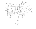
- FIG. 1 depicts a preferred embodiment according to the present invention.
- FIG. 1 depicts a sectional schematic view of a saddle fuel tank 100 having a tank shell 101.
- the tank shell 101 comprises a primary compartment 102, a secondary compartment 103 and a dome 400.
- the primary compartment 102 and the secondary compartment 103 are connected together in a communicating manner by means of a bridge 104.
- the bridge provides an exterior concavity 105 which is intended to provide accommodation for drive and/or exhaust components of the vehicle to pass freely underneath.
- a tank filler pipe 106 provides an entry for fuel into the fuel tank 100, wherein the primary compartment 102 is identified as the compartment first filled by fuel introduced from the filer pipe 106.
- a valve 200 is disposed within the fuel tank 100.
- the valve 200 is positioned at the centre of the tank, such that it extends above the bridge 104.
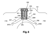
- FIG. 6 shows the valve 200 according to a preferred embodiment of the present invention.
- the valve 200 comprises a chamber 201.
- the chamber 201 of the valve is provided with a cover 202, which may either be moulded as one part with said chamber or it may form a separate part joined to the latter by any known means (mechanical fastening with a seal; welding etc.).
- This cover 202 is advantageously connected to a venting circuit via an aperture 203.
- the aperture 203 is connected through a conduit 301 to the inlet of a storage canister 302 (see Figure 1 ).
- the storage canister 302 has an outlet conduit 303 adapted for connection to the air inlet of an engine.
- valve 200 further comprises a refueling vent block 204.
- the refueling vent block 204 comprises:
- the first venting tube 206 and the second venting tube 207 are linear tubes and are arranged one to another such that they form an inverted "V".
- the tubes can have internal section comprised between 200mm 2 and 250mm 2 .
- the angle of the tubes can be defmed so that a clearance of, for example, 10mm is let between the tubes and the bridges.
- first venting tube 206 and the second venting tube 207 are curved tubes and are arranged one to another such that they form an inverted "U".
- curved tubes would be advantageous in the sense that they optimize both clearance, length and weight balance of the tubes.
- the base 205 is fixed to the chamber by any known means (clips, screws..).
- the base 205 is advantageously connected to (i.e. in communication with) the chamber 201 via an aperture 208.
- One extremity 2061 of the first venting tube opens onto the base 205 and an other extremity 2062 of the first venting tube opens onto the primary compartment 102.
- the extremity 2062 corresponds to a first shut-off level or first predetermined filling level L1.
- One extremity 2071 of the second venting tube opens onto the base 205 and an other extremity 2072 of the second venting tube opens onto the secondary compartment 103.
- the extremity 2072 corresponds to a second shut-off level or second predetermined filling level L2.
- the base 205 and the venting tubes 206 and 207 are made ofplastic.
- valve 200 As shown in figure 1 , the valve 200 according to a preferred embodiment of the present invention is designed to respond by taking a fully closed position when:
- the first predetermined filling level L1 is lower than the maximum filling level L3 of the primary compartment 102, which corresponds to the level of the top 1041 of the bridge 104.
- the second predetermined filling level L2 is also lower than the maximum filling level L4 of the secondary compartment 103, which corresponds to the level of the top 1041 of the bridge 104.
- valve 200 according to a preferred embodiment of the present invention comprises means for providing both the ROV function and the FLVV function.
- the volume of the two compartments 102 and 103 are the same, and the predetermined filling level L1 of the primary compartment 102 and the predetermined filling level L2 of the secondary compartment 103 are at the same level. It will be noted however that L1 and L2 may be at different levels, and especially when the volume of the two compartments are different.
- valve 200 responds as indicated in the case of figure 3 or in the case of figure 5 .
- the second predetermined filling level L2 is reached and the fuel tank 100 is filled.
- the first predetermined filling level L1 is reached and the fuel tank 100 is filled.
- Fuel 500 enters the primary compartment 102 from the tank filler pipe 106 in a refueling procedure, initiating filling of the primary compartment 102.
- the valve 200 remains open, as the second predetermined filling level L2 is not reached. In other words, the extremity 2072 of the second venting tube is still open. Because the valve 200 is open, the level of fuel 500 exceeds the first predetermined filling level L1.
- FIG 2 showing the fuel tank 100 in the course of the refuelling procedure in a situation in which the level of fuel 500 in the primary compartment 102 reaches the maximum filling level L3 of the primary compartment 102.
- the fuel 500 begins to flow over the top of the bridge 104 into the secondary compartment 103.
- the valve 200 is closed.
- the fuel tank 100 is no longer vented through the inwardly extending venting tube 206 and conduit 301.
- an increased pressure builds up in the vapour dome 400 in the fuel tank 100 and causes shut-off of the refueling operation.
- the secondary compartment 103 is first to be consumed during engine operation since the pump feeding the engine (not shown) is located therein.
- fuel 500 it is quite possible for fuel 500 to flow from the primary compartment 102 over the top of the bridge 104 into the secondary compartment 103 when the motor vehicle in which the fuel tank 100 is fitted is subjected to, for example, transverse acceleration during travelling in bends of a road.
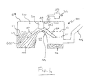
- FIG 4 showing the fuel tank 100 in a situation (also called "car rental" mode) in which the level of liquid is above L2 in the secondary compartment, under the influence of transverse acceleration.
- the valve 200 remains open, as the first predetermined filling level L1 is not reached.
- the extremity 2062 of the first venting tube is still open. In consequence, it is still possible to introduce fuel 500 from the tank filler pipe 106 into the primary compartment 102 because the valve 200 can carry out the venting of the fuel tank 100 through the inwardly extending venting tube 206 and conduit 301.
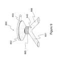
- valve according to the invention further comprises means which confer on it the ability to act as a pressure liquid vapour separator. Examples of this configuration are illustrated in relation to figures 7 to 9 .
- the valve 700 is disposed within the fuel tank 710.
- the valve 700 is positioned at the centre of the tank, such that it extends above the bridge 720.
- the valve 700 comprises a chamber 701.
- the chamber 701 of the valve is provided with a cover 702.
- This cover 702 is advantageously connected to a venting circuit via an aperture 703.
- the aperture 703 is connected through a conduit to the inlet of a storage canister 730.
- valve 700 further comprises a refueling vent block 704.
- the refueling vent block 704 comprises:
- valve 700 further comprises a semi-permeable membrane 708 mounted inside the chamber 701 such that it extends between the first 706 and second 707 venting tubes and the aperture 703.
- membrane 708 is configured such that:
- the membrane 708 allows only fuel vapour to be transferred to the canister 730 so as to avoid contamination and pass through to the atmosphere.
- the valve 800 is disposed within the fuel tank 810.
- the valve 800 is positioned at the centre of the tank, such that it extends above the bridge 820.
- the valve 800 comprises a chamber 801.
- the chamber 801 of the valve is provided with a cover 802.
- This cover 802 is advantageously connected to a venting circuit via an aperture 803.
- the aperture 803 is connected to the inlet of a recirculation pipe 831 of a refueling tube 832.
- valve 800 further comprises a refueling vent block 804.
- the refueling vent block 804 comprises:
- the valve 800 further comprises a semi-permeable membrane 808 mounted inside the chamber 801 such that it extends between the first 806 and second 807 venting tubes and the aperture 803.
- the membrane 808 discriminates liquid from flowing up the recirculation pipe 831.
- the valve 800 further comprises a small bleed orifice 840.
- this bleed orifice 840 is bored on the first venting tube 806.
- the bleed orifice 840 is used to minimize pressure spike at valve shut-off, in order to mitigate any fuel rising rapidly up the fill pipe and exiting the pipe as a result.
- This bleed orifice (23) could be tuned to optimize refueling performance.
- the valve 800 can comprise other bleed orifices placed at strategic locations in the refueling vent block 804.
Landscapes
- Engineering & Computer Science (AREA)
- Mechanical Engineering (AREA)
- Life Sciences & Earth Sciences (AREA)
- Sustainable Development (AREA)
- Sustainable Energy (AREA)
- Chemical & Material Sciences (AREA)
- Combustion & Propulsion (AREA)
- Transportation (AREA)
- Cooling, Air Intake And Gas Exhaust, And Fuel Tank Arrangements In Propulsion Units (AREA)
Abstract
a) a chamber provided with a cover, which extends at least partly into the tank and is connected via an upper venting aperture (203) to a venting circuit;
b) first means (206) for monitoring a level of liquid in the primary compartment;
c) second means (207) for monitoring a level of liquid in the secondary compartment;
- said first means detect that the level of liquid in the primary compartment is equal to or higher than a first predetermined filling level (L1); and
- said second means detect that the level of liquid in the secondary compartment is equal to or higher than a second predetermined filling level (L2).
Description
- The present invention relates to a method and a valve for the venting of a liquid tank, in particular a saddle fuel tank with which a motor vehicle may be equipped.
- Saddle fuel tanks are widely used for automotive applications. They are most frequently used with rear wheel drive or four wheel drive vehicles and they are designed to hold more fuel than a standard fuel tank.
- Generally, saddle fuel tanks include two compartments for storage of fuel, which are connected together in a communicating manner by means of a bridge. The bridge provides an exterior concavity which is intended to provide accommodation for drive and/or exhaust components of the vehicle to pass freely therethrough. Saddle fuel tanks, as most of the fuel tanks for motor vehicles, are nowadays generally provided with a venting circuit. This circuit allows air to be introduced into the tank in the event of underpressure (especially for compensating for the volume of liquid consumed) or allows the gases contained in the tank to be removed in the event of overpressure (especially in the event of overheating). This circuit also allows the ducting and possible filtering of the gases that have to be discharged into the atmosphere, for the purpose of meeting the ever stricter environmental requirements in this regard.
- The venting circuit generally includes a valve of the ROV (roll-over valve) type which as far as possible prevents liquid from coming out of the tank in the event of said tank rolling over or being at an excessively high angle of inclination. This valve must also respond rapidly and reliably when its intervention conditions occur, but with minimum sensitivity to abnormal phenomena such as especially a very high flow rate, overpressure in the tank or low-amplitude waves. This type of valve thus includes a vent function, a roll-over function and a liquid discrimination function.
- The venting circuit may also include a valve of the FLV (fill limit valve) type which sets the maximum filling level of the tank. It provides thus the fill-limit function.
- Some valves provide the functions from both an ROV and from a FLV.
- They are called FLVV (fill limit vent valve).
- Saddle tanks include a main (or primary) compartment and a secondary compartment, and include a transfer system that is in charge of transferring the liquid from the secondary compartment into the main compartment by mean of the fuel pump. This transfer system is continuously active as soon as the fuel pump is active, which means as soon as the contact is on.
- The transfer system implies that in a regular vehicle usage, the secondary compartment will have liquid in only if the main compartment is full. This configuration will lead to a so called "regular filling".
- However, an important transverse acceleration of the vehicle can transfer an important mass of liquid from the main compartment into the secondary compartment by mean of its own inertia submitted to this acceleration. If the contact is off at this moment, it results some liquid in the secondary compartment (possibly up to the level of the bridge) while the main compartment isn't full (possibly totally empty). This configuration will lead to a so called "rental-car filling".
- Generally, the fill limit valve of a saddle tank has a shut-off level (i.e. the level from which the valve takes a closed position) which is set above the level of the bridge. In this case whatever is the filling configuration in the two compartment, the filling behaviour will be the following; the tank is filled into the main compartment, when this one overflows, the secondary compartment is filled. When both compartments are full, the liquid rise up in the tank until the fill limit valve stops the filling process.
- However it happens that in some situation, constrained by the vehicle chassis or other OEM requirement, the shut-off level of the fill limit valve is set below the bridge level.
- In this situation, in order for a "regular filling" to be performed, the tank needs to have the fill limit valve positioned in the secondary compartment (the fill limit valve having its shut-off level set below the bridge level). However, in the case of a "rental-car filling", when the level of liquid in the secondary compartment is equal or above the shut-off level of the fill limit valve, the filling process stops (i.e. refueling of the main compartment is not possible, since the fill limit valve is closed).
- To overcome this problem, a known solution consists in disposing a first fill limit valve within the main compartment of the saddle tank (the one in which the filler pipe flows) and a second fill limit valve within the secondary compartment of the saddle tank. The shut-off level (i.e. the level from which the valve takes a closed position) of each valve is set below the level of the top of the bridge. The refueling of the saddle tank is possible until both valves are closed. This known solution ensures a complete filing of the saddle tank in any of the two previously mentioned situations of refueling.
- Disadvantages of this known solution are the complexity of the architecture and its expense since there are two valves to be mounted within the fuel tank. The complexity of this known solution is further increased by the fact that a plurality of conduits needs to be implemented for maintaining the two valves at the desired positions within the compartments and for making them communicate with the conduit that runs to a vapour storage canister. Fuel vapours are routinely vented to the canister from which they are later purged and burned.
- In view of the above-mentioned disadvantages, there exists a need for an improved method and valve for the venting of a saddle fuel tank.
- An object of the present invention is to solve these above-mentioned problems by proposing a method for venting of a liquid tank, the tank comprising a valve, a primary compartment and a secondary compartment which are connected together in a communicating manner by means of a bridge. According to one aspect of the present invention, the valve comprises:
- a) a chamber provided with a cover, which extends at least partly into the tank and is connected via an upper venting aperture to a venting circuit;
- b) first means for monitoring a level of liquid in the primary compartment;
- c) second means for monitoring a level of liquid in the secondary compartment;
the valve being configured to be closed when:- said first means detect that the level of liquid in the primary compartment is equal to or higher than a first predetermined filling level; and
- said second means detect that the level of liquid in the secondary compartment is equal to or higher than a second predetermined filling level.
- Thus, it is proposed to use a single valve for monitoring the level of liquid in both compartments of the tank. The valve according to the present invention is configured in such a way that both compartments are filled at a desired filling level in both "regular" and "rental car" refueling configurations.
- The valve according to the present invention is equipped with two means for monitoring which confer on it the ability to work with two shut-off levels (i.e. first predetermined filling level and second predetermined filling level). So, the valve according to the present invention has the particularity to be triggered as a function of two shut-off levels. These shut-off levels can be set at the same level or at two different levels. The refueling of the tank is then possible until both shut-off levels are reached. When both shut-off levels are reached, the valve takes a closed position.
- By the term "closed" is meant the fact that the communication between the inner volume of the tank and the upper venting aperture is obstructed/no longer active so that the tank can no longer be vented by the valve.
- The valve is intended for the venting circuit of a tank that may contain any liquid. In particular, the liquid may be a fuel, a brake fluid or a lubricant. More particularly, the liquid is a fuel. The tank may be intended for any use, especially for equipping a vehicle and even more especially for equipping a motor vehicle.
- The valve according to the invention comprises a chamber of any shape, usually of constant internal cross section. It preferably has a substantially cylindrical internal cross section. In an advantageous embodiment, the cover of the valve is pierced by an orifice preferably intended to be sealed by a float or any other sealing device preferably providing a ROV function as explained above.
- In one particular embodiment, the first and second means for monitoring are mechanical elements such as, for example, linear and/or curved plastic conduits.
- In another particular embodiment, the first and second means for monitoring are electronic sensors (for example, gage sensors)
- For a given tank having a given maximum filling volume, it is possible to advantageously set the shut-off levels of the valve according to the invention below the level of the bridge in order to make a new filling volume version requirement out of the same tank. For example, considering a tank with a maximum filling volume of 85 litres (with fill level above the level of the bridge), it is possible to reduce this maximum filling volume to 78 litres (with fill level below the level of the bridge), by setting appropriately the first and second predetermined filling levels below the top of the bridge.
- In a preferred embodiment, the valve is mounted within the tank such that its chamber extends above the bridge. The on-board diagnostic (OBD) for detecting leak in the fuel system requires the valve (that makes the tank to communicate with the canister) to be opened. The advantage of the configuration where the chamber of the valve extends above the bridge is that the valve can remain open at an excessively high angle of inclination of the tank, provided that the maximum filling level of the tank is not reached.
- In an advantageous embodiment, said first means comprise a first venting tube having one extremity (also called hereafter "inlet") which opens into the primary compartment at a level which corresponds to the first predetermined filling level, and an other extremity (also called hereafter "outlet") which opens into the chamber, and said second means comprise a second venting tube having one extremity (also called hereafter "inlet") which opens into the secondary compartment at a level which corresponds to the second predetermined filling level, and an other extremity (also called hereafter "outlet") which opens into the chamber. Here, it is proposed a dual port valve, i.e. a valve equipped with two gas inlets (i.e. the extremities of the tubes that open into the primary and secondary compartments). These gas inlets are located away from the chamber of the valve, so as to extend at the desired levels in the compartments of the tank. For this aim, the valve is advantageously equipped with two venting tubes. The tubes can have the same length or different lengths. The functional dimensions of those tubes are their inner section (which will set a pressure drop between the two extremity of the tubes, and the velocity of the fluids inside the tubes) and the height of their inlets (which will set the predetermined fill level). Such architecture is compact and easy to implement. The term "gas" is understood in particular to mean the external air that has to be introduced into the tank or the gas mixtures contained in the tank, the removal of which has to be possible. In the case of a fuel tank, these gas mixtures comprise essentially air, and fuel vapour.
- Advantageously, the valve comprises a base designed for supporting the first and second venting tubes and for connecting them to the chamber of the valve. The base according to the invention may have any shape. It preferably has a substantially cylindrical internal cross section. Preferably, this base is a cup shape part, with a flat bottom. Advantageously, the base is designed to be clipped onto the chamber. In another embodiment, the base comprises a threaded portion designed to be screwed on a corresponding threaded portion of the chamber. The first and second venting tubes are placed in communication (i.e. connected) with the chamber of the valve via a common aperture (i.e. the lower aperture of the chamber which corresponds to the upper aperture in the cup shaped base.
- In consequence, the flow of gas through this common aperture is possible until the lower extremity (i.e. the extremity that opened into a compartment) of both venting tubes are closed by the liquid.
- Advantageously, the base, the first and second venting tubes form one block. This architecture is compact and facilitate mounting/dismounting operations. In another particular embodiment, this one block also includes the chamber.
- In order to work properly, the valve must be entirely tight from the two inlets to the outlets. Otherwise there will be overfilling.
- In a preferred embodiment, the inlet section of the tubes extends horizontally (with respect to the bottom of the tank) in order to have a clear and precise shut-off.
- The tubes can be straight or curved. Curved tubes is advantageous in the way that it follows the shape of the bridge and doesn't extend too far in the compartments.
- In a preferred embodiment, the base and the first and second venting tubes are made by injection moulding a plastic.
- In a preferred embodiment, the first and second venting tubes are made of plastic. The term "plastic" is understood to mean any polymeric synthetic material, whether thermoplastic or thermosetting, which is in the solid state under ambient conditions, as well as blends of at least two of these materials.
- The main function of the valve according to the invention is the fill-limit function, but advantageously, the valve according to the invention can include a roll-over function, a venting function and a liquid discrimination function. These functions can be implemented by using a device comprising a float within a housing with a spring or ball below it in order to make the float closing before 90° rotation. On the top of the float there is a seal (preferably elastomeric or plastic) that seals the vent orifice in the top part of the housing when the float is in shut position.
- According to another aspect of the present invention, there is provided a saddle fuel tank equipped with a valve comprising first means for monitoring the level of liquid in a primary compartment of the tank and second means for monitoring the level of liquid in a secondary compartment of the tank, and being configured to be closed when :
- the first means detect that the level of liquid in the primary compartment is equal to or higher than a first predetermined filling level; and
- the second means detect that the level of liquid in the secondary compartment is equal to or higher than a second predetermined filling level.
- The invention will be illustrated in a non limiting manner by
figures 1 to 6 . -
Figure 1 is a schematic view of a fuel tank showing the maximum filling level of each of primary and secondary compartments of the fuel tank as well as the filling levels at which a valve according to the present invention is closed. -
Figure 2 is a schematic view of the fuel tank offigure 1 showing a situation in which the maximum filling level has been reached in the primary compartment during a refueling procedure. -
Figure 3 shows the fuel tank is filled, in which the maximum filling level has been reached in the secondary compartment, causing the stop of the refueling procedure. -
Figure 4 shows a situation in which, for example immediately prior to a refueling procedure, a relatively large amount of fuel has passed into the secondary compartment of the fuel tank to reach the maximum filling level of the secondary compartment due to transverse acceleration acting on a motor vehicle. -
Figure 5 shows the fuel tank is filled, in which the maximum filling level has been reached in the primary compartment, in the situation shown infigure 4 , causing the stop of the refueling procedure. -
Figure 6 shows a valve according to a preferred embodiment of the present invention (or at least one portion thereof). -
Figure 7 shows a valve comprising a semi-permeable membrane according to a first preferred embodiment of the present invention. -
Figures 8 and9 show a valve comprising a semi-permeable membrane according to a second preferred embodiment of the present invention. - Referring now to the drawings,
figures 1 through 6 depict a preferred embodiment according to the present invention. - Each of
figures 1 through 6 depicts a sectional schematic view of asaddle fuel tank 100 having atank shell 101. Thetank shell 101 comprises aprimary compartment 102, asecondary compartment 103 and adome 400. Theprimary compartment 102 and thesecondary compartment 103 are connected together in a communicating manner by means of abridge 104. The bridge provides anexterior concavity 105 which is intended to provide accommodation for drive and/or exhaust components of the vehicle to pass freely underneath. - A
tank filler pipe 106 provides an entry for fuel into thefuel tank 100, wherein theprimary compartment 102 is identified as the compartment first filled by fuel introduced from thefiler pipe 106. - A
valve 200 is disposed within thefuel tank 100. Preferably, thevalve 200 is positioned at the centre of the tank, such that it extends above thebridge 104. - Referring now to
figures 1 and6. Figure 6 shows thevalve 200 according to a preferred embodiment of the present invention. Thevalve 200 comprises achamber 201. Thechamber 201 of the valve is provided with acover 202, which may either be moulded as one part with said chamber or it may form a separate part joined to the latter by any known means (mechanical fastening with a seal; welding etc.). Thiscover 202 is advantageously connected to a venting circuit via anaperture 203. For example, theaperture 203 is connected through aconduit 301 to the inlet of a storage canister 302 (seeFigure 1 ). Thestorage canister 302 has anoutlet conduit 303 adapted for connection to the air inlet of an engine. - In the example shown on
figure 6 , thevalve 200 further comprises arefueling vent block 204. Therefueling vent block 204 comprises: - a base 205 designed to be mounted at the bottom of the
chamber 201; - a
first venting tube 206 in charge of monitoring a level of fuel in theprimary compartment 102; and - a
second venting tube 207 in charge of monitoring a level of fuel in thesecondary compartment 103. - In the illustrated example, the
first venting tube 206 and thesecond venting tube 207 are linear tubes and are arranged one to another such that they form an inverted "V". For example, the tubes can have internal section comprised between 200mm2 and 250mm2. The angle of the tubes can be defmed so that a clearance of, for example, 10mm is let between the tubes and the bridges. - In an alternative embodiment, the
first venting tube 206 and thesecond venting tube 207 are curved tubes and are arranged one to another such that they form an inverted "U". As mentioned earlier curved tubes would be advantageous in the sense that they optimize both clearance, length and weight balance of the tubes. - The
base 205 is fixed to the chamber by any known means (clips, screws..). Thebase 205 is advantageously connected to (i.e. in communication with) thechamber 201 via anaperture 208. Oneextremity 2061 of the first venting tube opens onto thebase 205 and another extremity 2062 of the first venting tube opens onto theprimary compartment 102. Theextremity 2062 corresponds to a first shut-off level or first predetermined filling level L1. Oneextremity 2071 of the second venting tube opens onto thebase 205 and another extremity 2072 of the second venting tube opens onto thesecondary compartment 103. Theextremity 2072 corresponds to a second shut-off level or second predetermined filling level L2. In a preferred embodiment, thebase 205 and the ventingtubes - As shown in
figure 1 , thevalve 200 according to a preferred embodiment of the present invention is designed to respond by taking a fully closed position when: - a fuel level in the
primary compartment 102 is equal to or higher than the first predetermined filling level L1; and - a fuel level in the
secondary compartment 103 is equal to or higher than the second predetermine filling level L2. - The first predetermined filling level L1 is lower than the maximum filling level L3 of the
primary compartment 102, which corresponds to the level of the top 1041 of thebridge 104. - The second predetermined filling level L2 is also lower than the maximum filling level L4 of the
secondary compartment 103, which corresponds to the level of the top 1041 of thebridge 104. - As will be described below, the
valve 200 according to a preferred embodiment of the present invention comprises means for providing both the ROV function and the FLVV function. - In the illustrated embodiment, the volume of the two
compartments primary compartment 102 and the predetermined filling level L2 of thesecondary compartment 103 are at the same level. It will be noted however that L1 and L2 may be at different levels, and especially when the volume of the two compartments are different. - As will be later described, refueling of the
fuel tank 100 is possible until thevalve 200 responds as indicated in the case offigure 3 or in the case offigure 5 . In the case offigure 3 , the second predetermined filling level L2 is reached and thefuel tank 100 is filled. In the case offigure 5 , the first predetermined filling level L1 is reached and thefuel tank 100 is filled. - Consideration will now be given to the
fuel tank 100 in a situation in which the level of liquid is below L2 in the secondary compartment ("regular" refueling procedure).Fuel 500 enters theprimary compartment 102 from thetank filler pipe 106 in a refueling procedure, initiating filling of theprimary compartment 102. When the level offuel 500 reaches the first predetermined filling level L1, thevalve 200 remains open, as the second predetermined filling level L2 is not reached. In other words, theextremity 2072 of the second venting tube is still open. Because thevalve 200 is open, the level offuel 500 exceeds the first predetermined filling level L1. - Reference will now be made particularly to
figure 2 showing thefuel tank 100 in the course of the refuelling procedure in a situation in which the level offuel 500 in theprimary compartment 102 reaches the maximum filling level L3 of theprimary compartment 102. In this situation, thefuel 500 begins to flow over the top of thebridge 104 into thesecondary compartment 103. When the level offuel 500 reaches the second predetermined filling level L2, thevalve 200 is closed. At this time, thefuel tank 100 is no longer vented through the inwardly extendingventing tube 206 andconduit 301. As a result, referring tofigure 3 showing thefuel tank 100 in a tank fill situation, an increased pressure builds up in thevapour dome 400 in thefuel tank 100 and causes shut-off of the refueling operation. - From this tank fill situation shown in
figure 3 , thesecondary compartment 103 is first to be consumed during engine operation since the pump feeding the engine (not shown) is located therein. Incidentally, it is quite possible forfuel 500 to flow from theprimary compartment 102 over the top of thebridge 104 into thesecondary compartment 103 when the motor vehicle in which thefuel tank 100 is fitted is subjected to, for example, transverse acceleration during travelling in bends of a road. Reference will be made tofigure 4 showing thefuel tank 100 in a situation (also called "car rental" mode) in which the level of liquid is above L2 in the secondary compartment, under the influence of transverse acceleration. In the situation shown infigure 4 , thevalve 200 remains open, as the first predetermined filling level L1 is not reached. In other words, theextremity 2062 of the first venting tube is still open. In consequence, it is still possible to introducefuel 500 from thetank filler pipe 106 into theprimary compartment 102 because thevalve 200 can carry out the venting of thefuel tank 100 through the inwardly extendingventing tube 206 andconduit 301. - Reference will be made to a tank fill situation shown in
figure 5 in which the refueling procedure ("car rental" refueling procedure) ends when the level offuel 500 in theprimary compartment 102 reaches the first predetermined filling level L1 at which theextremity 2062 of the first venting tube is closed. In this situation, thevalve 200 switches from an opened position to a closed position. As a result, an increased pressure builds up in thevapour dome 400 in thefuel tank 100 and causes shut-off of the refueling operation. - Advantageously, the valve according to the invention further comprises means which confer on it the ability to act as a pressure liquid vapour separator. Examples of this configuration are illustrated in relation to
figures 7 to 9 . - In a first advantageous embodiment shown on
figure 7 , thevalve 700 is disposed within thefuel tank 710. Preferably, thevalve 700 is positioned at the centre of the tank, such that it extends above thebridge 720. Thevalve 700 comprises achamber 701. Thechamber 701 of the valve is provided with acover 702. Thiscover 702 is advantageously connected to a venting circuit via anaperture 703. In the example offigure 7 , theaperture 703 is connected through a conduit to the inlet of astorage canister 730. - In the example shown on
figure 7 , thevalve 700 further comprises arefueling vent block 704. Therefueling vent block 704 comprises: - a base 705 designed to be mounted at the bottom of the
chamber 701; - a
first venting tube 706 in charge of monitoring a level of fuel in the primary compartment of the tank; and - a
second venting tube 707 in charge of monitoring a level of fuel in the secondary compartment of the tank. - Advantageously, the
valve 700 further comprises asemi-permeable membrane 708 mounted inside thechamber 701 such that it extends between the first 706 and second 707 venting tubes and theaperture 703. Themembrane 708 is configured such that: - it allows liquid vapour within the tank to flow from the first and second venting tubes to the aperture; and
- it prevents liquid in the tank to flow from the first and second venting tubes to the aperture.
- Thus, the
membrane 708 allows only fuel vapour to be transferred to thecanister 730 so as to avoid contamination and pass through to the atmosphere. - In a second advantageous embodiment shown on
figures 8 and9 , thevalve 800 is disposed within thefuel tank 810. Preferably, thevalve 800 is positioned at the centre of the tank, such that it extends above thebridge 820. Thevalve 800 comprises achamber 801. Thechamber 801 of the valve is provided with acover 802. Thiscover 802 is advantageously connected to a venting circuit via anaperture 803. In the example offigure 8 , theaperture 803 is connected to the inlet of arecirculation pipe 831 of arefueling tube 832. - In the example shown on
figure 8 , thevalve 800 further comprises arefueling vent block 804. Therefueling vent block 804 comprises: - a base 805 designed to be mounted at the bottom of the
chamber 801; - a
first venting tube 806 in charge of monitoring a level of fuel in the primary compartment of the tank; and - a
second venting tube 807 in charge of monitoring a level of fuel in the secondary compartment of the tank. - Advantageously, the
valve 800 further comprises asemi-permeable membrane 808 mounted inside thechamber 801 such that it extends between the first 806 and second 807 venting tubes and theaperture 803. In this particular embodiment, themembrane 808 discriminates liquid from flowing up therecirculation pipe 831. - Advantageously, as illustrated in the example of
figure 9 , thevalve 800 further comprises asmall bleed orifice 840. For example, thisbleed orifice 840 is bored on thefirst venting tube 806. Thebleed orifice 840 is used to minimize pressure spike at valve shut-off, in order to mitigate any fuel rising rapidly up the fill pipe and exiting the pipe as a result. This bleed orifice (23) could be tuned to optimize refueling performance. Thevalve 800 can comprise other bleed orifices placed at strategic locations in therefueling vent block 804.
Claims (14)
- Method for venting a liquid tank (100), the tank comprising a valve (200), a primary compartment (102) and a secondary compartment (103) which are connected together in a communicating manner by means of a bridge (104), wherein the valve comprises:a) a chamber (201) provided with a cover, which extends at least partly into the tank and is connected via an upper venting aperture (203) to a venting circuit;b) first means (206) for monitoring a level of liquid in the primary compartment;c) second means (207) for monitoring a level of liquid in the secondarythe valve being configured to be closed when:
compartment;- said first means detect that the level of liquid in the primary compartment is equal to or higher than a first predetermined filling level (L1); and- said second means detect that the level of liquid in the secondary compartment is equal to or higher than a second predetermined filling level (L2). - Method according to claim 1, wherein the first and second predetermined filling levels are lower than the level of the top of the bridge.
- Method according to any one of claims 1 and 2, wherein the valve is mounted within the tank such that its chamber extends above the bridge.
- Method according to any one of claims 1 to 3, wherein:- said first means comprise a first venting tube having one extremity which opens into the primary compartment at a level which corresponds to the first predetermined filling level, and an other extremity which opens into the chamber, and- said second means comprise a second venting tube having one extremity which opens into the secondary compartment at a level which corresponds to the second predetermined filling level, and an other extremity which opens into the chamber.
- Method according to any one of claims 1 to 4, using a device with a ROV (roll-over valve) function able to cooperate with the upper venting aperture.
- Valve suitable for a method according to any one of claims 1 to 5, said valve comprising:a) a chamber provided with a cover and with an upper venting aperture suitable for being connected to a venting circuit;b) first means for monitoring a level of liquid in a primary compartment of a tank;c) second means for monitoring a level of liquid in a secondary compartmentthe valve being configured to be closed when :
of the tank;- said first means detect that the level of liquid in the primary compartment is equal to or higher than a first predetermined filling level; and- said second means detect that the level of liquid in the secondary compartment is equal to or higher than a second predetermined filling level. - Valve according to claim 6, wherein:- said first means comprise a first venting tube having one extremity which opens into the primary compartment at a level which corresponds to the first predetermined filling level, and an other extremity which opens into the chamber, and- said second means comprise a second venting tube having one extremity which opens into the secondary compartment at a level which corresponds to the second predetermined filling level, and an other extremity which opens into the chamber.
- Valve according to claim 7, said valve comprising a base designed for supporting the first and second venting tubes and for connecting them to the chamber of the valve.
- Valve according to claim 8, wherein the base and the first and second venting tubes form one block.
- Valve according to claim 8, wherein the base and the first and second venting tubes are made by injection moulding a plastic.
- Valve according to any one of claims 7 to 9, wherein the first and second venting tubes are made of plastic.
- Valve according to any one of claims 7 to 11, said valve comprising at least one semi-permeable membrane mounted inside the chamber such that it extends between the first and second venting tubes and the upper venting aperture, the semi-permeable membrane being configured such that:- it allows liquid vapour within the tank to flow from the first and second venting tubes to the upper venting aperture; and- it prevents liquid in the tank to flow from the first and second venting tubes to the upper venting aperture.
- Valve according to any one of claims 6 to 12, said valve comprising at least one bleed orifice.
- Saddle fuel tank equipped with a valve according to any one of claims 6 to 13.
Priority Applications (4)
| Application Number | Priority Date | Filing Date | Title |
|---|---|---|---|
| EP20120162989 EP2647516B1 (en) | 2012-04-03 | 2012-04-03 | Method and valve for the venting of a saddle fuel tank |
| US13/855,236 US8910675B2 (en) | 2012-04-03 | 2013-04-02 | Method and valve for the venting of a saddle fuel tank |
| PCT/EP2013/056976 WO2013150047A1 (en) | 2012-04-03 | 2013-04-03 | Method and valve for the venting of a saddle fuel tank |
| CN201380029396.6A CN104470748B (en) | 2012-04-03 | 2013-04-03 | Method and valve for venting a saddle fuel tank |
Applications Claiming Priority (1)
| Application Number | Priority Date | Filing Date | Title |
|---|---|---|---|
| EP20120162989 EP2647516B1 (en) | 2012-04-03 | 2012-04-03 | Method and valve for the venting of a saddle fuel tank |
Publications (2)
| Publication Number | Publication Date |
|---|---|
| EP2647516A1 true EP2647516A1 (en) | 2013-10-09 |
| EP2647516B1 EP2647516B1 (en) | 2014-12-17 |
Family
ID=46044366
Family Applications (1)
| Application Number | Title | Priority Date | Filing Date |
|---|---|---|---|
| EP20120162989 Active EP2647516B1 (en) | 2012-04-03 | 2012-04-03 | Method and valve for the venting of a saddle fuel tank |
Country Status (4)
| Country | Link |
|---|---|
| US (1) | US8910675B2 (en) |
| EP (1) | EP2647516B1 (en) |
| CN (1) | CN104470748B (en) |
| WO (1) | WO2013150047A1 (en) |
Families Citing this family (15)
| Publication number | Priority date | Publication date | Assignee | Title |
|---|---|---|---|---|
| DE102011014713B4 (en) * | 2011-03-23 | 2016-05-19 | Audi Ag | Tank ventilation device for a motor vehicle |
| EP2647517B1 (en) * | 2012-04-03 | 2015-01-14 | Inergy Automotive Systems Research (Société Anonyme) | Solid state venting valve for a fuel tank |
| US9453583B1 (en) * | 2013-07-12 | 2016-09-27 | Best Fabrications Inc. | Vent for tank |
| EP2823980B1 (en) | 2013-07-12 | 2016-04-20 | Inergy Automotive Systems Research (Société Anonyme) | Valve for venting a fuel tank |
| FR3011610B1 (en) * | 2013-10-07 | 2015-11-13 | Inergy Automotive Systems Res | FILL LIMIT VALVE FOR FUEL TANK |
| JP6287144B2 (en) * | 2013-12-06 | 2018-03-07 | ブラザー工業株式会社 | Inkjet recording apparatus, multifunction machine, and ink cartridge container |
| US9926104B2 (en) * | 2015-07-28 | 2018-03-27 | Stackcan Llc | Container system and apparatus |
| CN106882036B (en) * | 2015-12-16 | 2021-09-10 | 现代自动车株式会社 | Roll-over valve for a fuel tank of a vehicle |
| EP3184341A1 (en) * | 2015-12-22 | 2017-06-28 | Plastic Omnium Advanced Innovation and Research | Valve apparatus with a weight control system |
| ITUA20161864A1 (en) * | 2016-03-21 | 2017-09-21 | Magneti Marelli Spa | FUEL TANK AND FUEL SUPPLY SYSTEM FOR AN INTERNAL COMBUSTION ENGINE |
| JP2018094967A (en) * | 2016-12-08 | 2018-06-21 | 本田技研工業株式会社 | Vertical fuel tank |
| DE102017202120A1 (en) * | 2017-02-10 | 2018-08-16 | Volkswagen Aktiengesellschaft | Protective housing for a fuel tank and inspection method |
| US10906798B2 (en) | 2019-03-12 | 2021-02-02 | Ford Global Technologies, Llc | Systems and methods for reducing saddle fuel tank depressurization time |
| DE102019112741B3 (en) * | 2019-05-15 | 2020-05-20 | Ktm Ag | Fuel tank arrangement with at least two separate tank bodies |
| US12408756B1 (en) | 2022-05-27 | 2025-09-09 | Series International, Llc | Stacking chair with removable back |
Citations (4)
| Publication number | Priority date | Publication date | Assignee | Title |
|---|---|---|---|---|
| US20010013516A1 (en) * | 2000-02-14 | 2001-08-16 | Albert Boecker | Fuel tank and method for its production |
| DE10060239A1 (en) * | 2000-12-05 | 2002-06-06 | Audi Ag | Venting system with activated carbon filter for vehicle fuel tank, includes pump to empty compensation tank in defined operational states |
| US20070189906A1 (en) * | 2004-08-31 | 2007-08-16 | Sandor Palvolgyi | Multichamber tank for motor vehicles |
| EP2045111A2 (en) * | 2007-10-01 | 2009-04-08 | Nissan Motor Co., Ltd. | Fuel tank |
Family Cites Families (9)
| Publication number | Priority date | Publication date | Assignee | Title |
|---|---|---|---|---|
| JPH0413235Y2 (en) * | 1985-09-13 | 1992-03-27 | ||
| US4765359A (en) * | 1987-04-23 | 1988-08-23 | Burnett Jonathan P | Filling manifold for plural fuel tanks |
| DE50003990D1 (en) * | 1999-10-28 | 2003-11-13 | Bayerische Motoren Werke Ag | FUEL TANK FOR A FUEL VEHICLE |
| JP3948194B2 (en) * | 2000-06-27 | 2007-07-25 | 日産自動車株式会社 | Fuel tank refueling amount regulating valve and fuel tank device |
| DE10227524A1 (en) * | 2002-06-20 | 2004-01-08 | Daimlerchrysler Ag | Fuel tank system |
| US8171952B2 (en) * | 2008-02-01 | 2012-05-08 | Eaton Corporation | Multi-function control valve for fuel vapor system |
| JP5242440B2 (en) * | 2008-04-18 | 2013-07-24 | 株式会社ニフコ | Fuel tank valve device and fuel tank supercharging prevention device |
| DE102009010406B4 (en) * | 2009-02-26 | 2011-09-22 | Magna Steyr Fuel Systems Gesmbh | Filling head for a fuel tank with a protective device |
| US8622074B2 (en) * | 2012-01-26 | 2014-01-07 | Ti Automotive Technology Center Gmbh | Fuel tank venting system |
-
2012
- 2012-04-03 EP EP20120162989 patent/EP2647516B1/en active Active
-
2013
- 2013-04-02 US US13/855,236 patent/US8910675B2/en active Active
- 2013-04-03 CN CN201380029396.6A patent/CN104470748B/en active Active
- 2013-04-03 WO PCT/EP2013/056976 patent/WO2013150047A1/en not_active Ceased
Patent Citations (4)
| Publication number | Priority date | Publication date | Assignee | Title |
|---|---|---|---|---|
| US20010013516A1 (en) * | 2000-02-14 | 2001-08-16 | Albert Boecker | Fuel tank and method for its production |
| DE10060239A1 (en) * | 2000-12-05 | 2002-06-06 | Audi Ag | Venting system with activated carbon filter for vehicle fuel tank, includes pump to empty compensation tank in defined operational states |
| US20070189906A1 (en) * | 2004-08-31 | 2007-08-16 | Sandor Palvolgyi | Multichamber tank for motor vehicles |
| EP2045111A2 (en) * | 2007-10-01 | 2009-04-08 | Nissan Motor Co., Ltd. | Fuel tank |
Also Published As
| Publication number | Publication date |
|---|---|
| US20130255797A1 (en) | 2013-10-03 |
| CN104470748A (en) | 2015-03-25 |
| CN104470748B (en) | 2017-03-29 |
| WO2013150047A1 (en) | 2013-10-10 |
| EP2647516B1 (en) | 2014-12-17 |
| US8910675B2 (en) | 2014-12-16 |
Similar Documents
| Publication | Publication Date | Title |
|---|---|---|
| EP2647516B1 (en) | Method and valve for the venting of a saddle fuel tank | |
| US6675779B2 (en) | Dual float valve for fuel tank vent with liquid carryover filter | |
| EP2045111B1 (en) | Fuel tank | |
| US6634341B2 (en) | Vent and rollover valve and fuel pump module | |
| US20010011538A1 (en) | Vent valve and fuel pump module | |
| JP6124605B2 (en) | Fuel tank degasser | |
| EP2607135B1 (en) | Fuel ventilation system valve | |
| AU2010247088A1 (en) | Fuel vapor vent valve with dynamic pressure relief | |
| US9925864B2 (en) | Method and valve for venting a fuel tank | |
| WO2018085325A1 (en) | Fill limit venting valve with high shut-off height | |
| RU2581789C2 (en) | Liquid container for vehicle | |
| JP2004324570A (en) | Fuel flow-out regulation device for fuel tank | |
| KR20110016965A (en) | Small engine fuel system | |
| KR20130114746A (en) | Pressure equalizing valve for a fuel tank or secondary fluid tank on a motor vehicle | |
| US9592729B2 (en) | Fuel tank | |
| CA2956828A1 (en) | Breather check valve | |
| EP3040227A1 (en) | System and method for controlling fuel vapor recovery and controller for use in such a system and method | |
| US9982623B2 (en) | Apparatus and method for preventing overflow of fuel from vehicle fuel tank | |
| JP4847370B2 (en) | Vehicle fuel tank | |
| CN209414021U (en) | Ventilation valve module and aerating system and fuel tank system for fuel tank | |
| JP2008221914A (en) | Vehicle fuel tank | |
| JP5428993B2 (en) | Supercharging prevention device | |
| CN111942145A (en) | Exhaust device for venting a motor vehicle tank | |
| US9347403B2 (en) | Fuel tank | |
| US20050235968A1 (en) | Fuel vapor recovery system |
Legal Events
| Date | Code | Title | Description |
|---|---|---|---|
| PUAI | Public reference made under article 153(3) epc to a published international application that has entered the european phase |
Free format text: ORIGINAL CODE: 0009012 |
|
| AK | Designated contracting states |
Kind code of ref document: A1 Designated state(s): AL AT BE BG CH CY CZ DE DK EE ES FI FR GB GR HR HU IE IS IT LI LT LU LV MC MK MT NL NO PL PT RO RS SE SI SK SM TR |
|
| AX | Request for extension of the european patent |
Extension state: BA ME |
|
| 17P | Request for examination filed |
Effective date: 20140408 |
|
| RBV | Designated contracting states (corrected) |
Designated state(s): AL AT BE BG CH CY CZ DE DK EE ES FI FR GB GR HR HU IE IS IT LI LT LU LV MC MK MT NL NO PL PT RO RS SE SI SK SM TR |
|
| GRAP | Despatch of communication of intention to grant a patent |
Free format text: ORIGINAL CODE: EPIDOSNIGR1 |
|
| RIC1 | Information provided on ipc code assigned before grant |
Ipc: B60K 15/03 20060101ALI20140626BHEP Ipc: B60K 15/035 20060101AFI20140626BHEP Ipc: B62J 37/00 20060101ALI20140626BHEP |
|
| INTG | Intention to grant announced |
Effective date: 20140710 |
|
| GRAS | Grant fee paid |
Free format text: ORIGINAL CODE: EPIDOSNIGR3 |
|
| GRAA | (expected) grant |
Free format text: ORIGINAL CODE: 0009210 |
|
| AK | Designated contracting states |
Kind code of ref document: B1 Designated state(s): AL AT BE BG CH CY CZ DE DK EE ES FI FR GB GR HR HU IE IS IT LI LT LU LV MC MK MT NL NO PL PT RO RS SE SI SK SM TR |
|
| REG | Reference to a national code |
Ref country code: GB Ref legal event code: FG4D |
|
| REG | Reference to a national code |
Ref country code: CH Ref legal event code: EP |
|
| REG | Reference to a national code |
Ref country code: IE Ref legal event code: FG4D |
|
| REG | Reference to a national code |
Ref country code: AT Ref legal event code: REF Ref document number: 701617 Country of ref document: AT Kind code of ref document: T Effective date: 20150115 |
|
| REG | Reference to a national code |
Ref country code: DE Ref legal event code: R096 Ref document number: 602012004297 Country of ref document: DE Effective date: 20150219 |
|
| PG25 | Lapsed in a contracting state [announced via postgrant information from national office to epo] |
Ref country code: LT Free format text: LAPSE BECAUSE OF FAILURE TO SUBMIT A TRANSLATION OF THE DESCRIPTION OR TO PAY THE FEE WITHIN THE PRESCRIBED TIME-LIMIT Effective date: 20141217 Ref country code: FI Free format text: LAPSE BECAUSE OF FAILURE TO SUBMIT A TRANSLATION OF THE DESCRIPTION OR TO PAY THE FEE WITHIN THE PRESCRIBED TIME-LIMIT Effective date: 20141217 Ref country code: NO Free format text: LAPSE BECAUSE OF FAILURE TO SUBMIT A TRANSLATION OF THE DESCRIPTION OR TO PAY THE FEE WITHIN THE PRESCRIBED TIME-LIMIT Effective date: 20150317 |
|
| REG | Reference to a national code |
Ref country code: LT Ref legal event code: MG4D |
|
| PG25 | Lapsed in a contracting state [announced via postgrant information from national office to epo] |
Ref country code: SE Free format text: LAPSE BECAUSE OF FAILURE TO SUBMIT A TRANSLATION OF THE DESCRIPTION OR TO PAY THE FEE WITHIN THE PRESCRIBED TIME-LIMIT Effective date: 20141217 Ref country code: RS Free format text: LAPSE BECAUSE OF FAILURE TO SUBMIT A TRANSLATION OF THE DESCRIPTION OR TO PAY THE FEE WITHIN THE PRESCRIBED TIME-LIMIT Effective date: 20141217 Ref country code: LV Free format text: LAPSE BECAUSE OF FAILURE TO SUBMIT A TRANSLATION OF THE DESCRIPTION OR TO PAY THE FEE WITHIN THE PRESCRIBED TIME-LIMIT Effective date: 20141217 Ref country code: HR Free format text: LAPSE BECAUSE OF FAILURE TO SUBMIT A TRANSLATION OF THE DESCRIPTION OR TO PAY THE FEE WITHIN THE PRESCRIBED TIME-LIMIT Effective date: 20141217 Ref country code: GR Free format text: LAPSE BECAUSE OF FAILURE TO SUBMIT A TRANSLATION OF THE DESCRIPTION OR TO PAY THE FEE WITHIN THE PRESCRIBED TIME-LIMIT Effective date: 20150318 |
|
| REG | Reference to a national code |
Ref country code: AT Ref legal event code: MK05 Ref document number: 701617 Country of ref document: AT Kind code of ref document: T Effective date: 20141217 |
|
| PG25 | Lapsed in a contracting state [announced via postgrant information from national office to epo] |
Ref country code: NL Free format text: LAPSE BECAUSE OF FAILURE TO SUBMIT A TRANSLATION OF THE DESCRIPTION OR TO PAY THE FEE WITHIN THE PRESCRIBED TIME-LIMIT Effective date: 20141217 |
|
| PG25 | Lapsed in a contracting state [announced via postgrant information from national office to epo] |
Ref country code: RO Free format text: LAPSE BECAUSE OF FAILURE TO SUBMIT A TRANSLATION OF THE DESCRIPTION OR TO PAY THE FEE WITHIN THE PRESCRIBED TIME-LIMIT Effective date: 20141217 Ref country code: SK Free format text: LAPSE BECAUSE OF FAILURE TO SUBMIT A TRANSLATION OF THE DESCRIPTION OR TO PAY THE FEE WITHIN THE PRESCRIBED TIME-LIMIT Effective date: 20141217 Ref country code: CZ Free format text: LAPSE BECAUSE OF FAILURE TO SUBMIT A TRANSLATION OF THE DESCRIPTION OR TO PAY THE FEE WITHIN THE PRESCRIBED TIME-LIMIT Effective date: 20141217 Ref country code: EE Free format text: LAPSE BECAUSE OF FAILURE TO SUBMIT A TRANSLATION OF THE DESCRIPTION OR TO PAY THE FEE WITHIN THE PRESCRIBED TIME-LIMIT Effective date: 20141217 Ref country code: ES Free format text: LAPSE BECAUSE OF FAILURE TO SUBMIT A TRANSLATION OF THE DESCRIPTION OR TO PAY THE FEE WITHIN THE PRESCRIBED TIME-LIMIT Effective date: 20141217 |
|
| PG25 | Lapsed in a contracting state [announced via postgrant information from national office to epo] |
Ref country code: PL Free format text: LAPSE BECAUSE OF FAILURE TO SUBMIT A TRANSLATION OF THE DESCRIPTION OR TO PAY THE FEE WITHIN THE PRESCRIBED TIME-LIMIT Effective date: 20141217 Ref country code: IS Free format text: LAPSE BECAUSE OF FAILURE TO SUBMIT A TRANSLATION OF THE DESCRIPTION OR TO PAY THE FEE WITHIN THE PRESCRIBED TIME-LIMIT Effective date: 20150417 Ref country code: AT Free format text: LAPSE BECAUSE OF FAILURE TO SUBMIT A TRANSLATION OF THE DESCRIPTION OR TO PAY THE FEE WITHIN THE PRESCRIBED TIME-LIMIT Effective date: 20141217 |
|
| REG | Reference to a national code |
Ref country code: DE Ref legal event code: R097 Ref document number: 602012004297 Country of ref document: DE |
|
| PLBE | No opposition filed within time limit |
Free format text: ORIGINAL CODE: 0009261 |
|
| STAA | Information on the status of an ep patent application or granted ep patent |
Free format text: STATUS: NO OPPOSITION FILED WITHIN TIME LIMIT |
|
| PG25 | Lapsed in a contracting state [announced via postgrant information from national office to epo] |
Ref country code: DK Free format text: LAPSE BECAUSE OF FAILURE TO SUBMIT A TRANSLATION OF THE DESCRIPTION OR TO PAY THE FEE WITHIN THE PRESCRIBED TIME-LIMIT Effective date: 20141217 |
|
| 26N | No opposition filed |
Effective date: 20150918 |
|
| PG25 | Lapsed in a contracting state [announced via postgrant information from national office to epo] |
Ref country code: MC Free format text: LAPSE BECAUSE OF FAILURE TO SUBMIT A TRANSLATION OF THE DESCRIPTION OR TO PAY THE FEE WITHIN THE PRESCRIBED TIME-LIMIT Effective date: 20141217 Ref country code: LU Free format text: LAPSE BECAUSE OF FAILURE TO SUBMIT A TRANSLATION OF THE DESCRIPTION OR TO PAY THE FEE WITHIN THE PRESCRIBED TIME-LIMIT Effective date: 20150403 |
|
| REG | Reference to a national code |
Ref country code: CH Ref legal event code: PL |
|
| PG25 | Lapsed in a contracting state [announced via postgrant information from national office to epo] |
Ref country code: IT Free format text: LAPSE BECAUSE OF FAILURE TO SUBMIT A TRANSLATION OF THE DESCRIPTION OR TO PAY THE FEE WITHIN THE PRESCRIBED TIME-LIMIT Effective date: 20141217 |
|
| REG | Reference to a national code |
Ref country code: IE Ref legal event code: MM4A |
|
| PG25 | Lapsed in a contracting state [announced via postgrant information from national office to epo] |
Ref country code: CH Free format text: LAPSE BECAUSE OF NON-PAYMENT OF DUE FEES Effective date: 20150430 Ref country code: LI Free format text: LAPSE BECAUSE OF NON-PAYMENT OF DUE FEES Effective date: 20150430 |
|
| PG25 | Lapsed in a contracting state [announced via postgrant information from national office to epo] |
Ref country code: SI Free format text: LAPSE BECAUSE OF FAILURE TO SUBMIT A TRANSLATION OF THE DESCRIPTION OR TO PAY THE FEE WITHIN THE PRESCRIBED TIME-LIMIT Effective date: 20141217 |
|
| REG | Reference to a national code |
Ref country code: FR Ref legal event code: PLFP Year of fee payment: 5 |
|
| PG25 | Lapsed in a contracting state [announced via postgrant information from national office to epo] |
Ref country code: IE Free format text: LAPSE BECAUSE OF NON-PAYMENT OF DUE FEES Effective date: 20150403 |
|
| PG25 | Lapsed in a contracting state [announced via postgrant information from national office to epo] |
Ref country code: BE Free format text: LAPSE BECAUSE OF FAILURE TO SUBMIT A TRANSLATION OF THE DESCRIPTION OR TO PAY THE FEE WITHIN THE PRESCRIBED TIME-LIMIT Effective date: 20141217 |
|
| GBPC | Gb: european patent ceased through non-payment of renewal fee |
Effective date: 20160403 |
|
| PG25 | Lapsed in a contracting state [announced via postgrant information from national office to epo] |
Ref country code: MT Free format text: LAPSE BECAUSE OF FAILURE TO SUBMIT A TRANSLATION OF THE DESCRIPTION OR TO PAY THE FEE WITHIN THE PRESCRIBED TIME-LIMIT Effective date: 20141217 |
|
| PG25 | Lapsed in a contracting state [announced via postgrant information from national office to epo] |
Ref country code: GB Free format text: LAPSE BECAUSE OF NON-PAYMENT OF DUE FEES Effective date: 20160403 |
|
| REG | Reference to a national code |
Ref country code: FR Ref legal event code: PLFP Year of fee payment: 6 |
|
| PG25 | Lapsed in a contracting state [announced via postgrant information from national office to epo] |
Ref country code: HU Free format text: LAPSE BECAUSE OF FAILURE TO SUBMIT A TRANSLATION OF THE DESCRIPTION OR TO PAY THE FEE WITHIN THE PRESCRIBED TIME-LIMIT; INVALID AB INITIO Effective date: 20120403 Ref country code: SM Free format text: LAPSE BECAUSE OF FAILURE TO SUBMIT A TRANSLATION OF THE DESCRIPTION OR TO PAY THE FEE WITHIN THE PRESCRIBED TIME-LIMIT Effective date: 20141217 Ref country code: BG Free format text: LAPSE BECAUSE OF FAILURE TO SUBMIT A TRANSLATION OF THE DESCRIPTION OR TO PAY THE FEE WITHIN THE PRESCRIBED TIME-LIMIT Effective date: 20141217 |
|
| PG25 | Lapsed in a contracting state [announced via postgrant information from national office to epo] |
Ref country code: CY Free format text: LAPSE BECAUSE OF FAILURE TO SUBMIT A TRANSLATION OF THE DESCRIPTION OR TO PAY THE FEE WITHIN THE PRESCRIBED TIME-LIMIT Effective date: 20141217 |
|
| PG25 | Lapsed in a contracting state [announced via postgrant information from national office to epo] |
Ref country code: PT Free format text: LAPSE BECAUSE OF FAILURE TO SUBMIT A TRANSLATION OF THE DESCRIPTION OR TO PAY THE FEE WITHIN THE PRESCRIBED TIME-LIMIT Effective date: 20150417 |
|
| PG25 | Lapsed in a contracting state [announced via postgrant information from national office to epo] |
Ref country code: TR Free format text: LAPSE BECAUSE OF FAILURE TO SUBMIT A TRANSLATION OF THE DESCRIPTION OR TO PAY THE FEE WITHIN THE PRESCRIBED TIME-LIMIT Effective date: 20141217 |
|
| REG | Reference to a national code |
Ref country code: FR Ref legal event code: PLFP Year of fee payment: 7 |
|
| PG25 | Lapsed in a contracting state [announced via postgrant information from national office to epo] |
Ref country code: MK Free format text: LAPSE BECAUSE OF FAILURE TO SUBMIT A TRANSLATION OF THE DESCRIPTION OR TO PAY THE FEE WITHIN THE PRESCRIBED TIME-LIMIT Effective date: 20141217 |
|
| PG25 | Lapsed in a contracting state [announced via postgrant information from national office to epo] |
Ref country code: AL Free format text: LAPSE BECAUSE OF FAILURE TO SUBMIT A TRANSLATION OF THE DESCRIPTION OR TO PAY THE FEE WITHIN THE PRESCRIBED TIME-LIMIT Effective date: 20141217 |
|
| P01 | Opt-out of the competence of the unified patent court (upc) registered |
Effective date: 20230515 |
|
| REG | Reference to a national code |
Ref country code: DE Ref legal event code: R081 Ref document number: 602012004297 Country of ref document: DE Owner name: OPMOBILITY C-POWER BELGIUM RESEARCH, BE Free format text: FORMER OWNER: INERGY AUTOMOTIVE SYSTEMS RESEARCH (SA), BRUXELLES, BE |
|
| PGFP | Annual fee paid to national office [announced via postgrant information from national office to epo] |
Ref country code: DE Payment date: 20250422 Year of fee payment: 14 |
|
| PGFP | Annual fee paid to national office [announced via postgrant information from national office to epo] |
Ref country code: FR Payment date: 20250429 Year of fee payment: 14 |