EP2647404A1 - Guidewire - Google Patents
Guidewire Download PDFInfo
- Publication number
- EP2647404A1 EP2647404A1 EP13157645.6A EP13157645A EP2647404A1 EP 2647404 A1 EP2647404 A1 EP 2647404A1 EP 13157645 A EP13157645 A EP 13157645A EP 2647404 A1 EP2647404 A1 EP 2647404A1
- Authority
- EP
- European Patent Office
- Prior art keywords
- leading end
- end segment
- guidewire
- segment
- finger
- Prior art date
- Legal status (The legal status is an assumption and is not a legal conclusion. Google has not performed a legal analysis and makes no representation as to the accuracy of the status listed.)
- Granted
Links
Images



Classifications
-
- A—HUMAN NECESSITIES
- A61—MEDICAL OR VETERINARY SCIENCE; HYGIENE
- A61M—DEVICES FOR INTRODUCING MEDIA INTO, OR ONTO, THE BODY; DEVICES FOR TRANSDUCING BODY MEDIA OR FOR TAKING MEDIA FROM THE BODY; DEVICES FOR PRODUCING OR ENDING SLEEP OR STUPOR
- A61M25/00—Catheters; Hollow probes
- A61M25/01—Introducing, guiding, advancing, emplacing or holding catheters
- A61M25/09—Guide wires
-
- A—HUMAN NECESSITIES
- A61—MEDICAL OR VETERINARY SCIENCE; HYGIENE
- A61M—DEVICES FOR INTRODUCING MEDIA INTO, OR ONTO, THE BODY; DEVICES FOR TRANSDUCING BODY MEDIA OR FOR TAKING MEDIA FROM THE BODY; DEVICES FOR PRODUCING OR ENDING SLEEP OR STUPOR
- A61M25/00—Catheters; Hollow probes
- A61M25/01—Introducing, guiding, advancing, emplacing or holding catheters
- A61M25/09—Guide wires
- A61M2025/09058—Basic structures of guide wires
- A61M2025/09083—Basic structures of guide wires having a coil around a core
-
- A—HUMAN NECESSITIES
- A61—MEDICAL OR VETERINARY SCIENCE; HYGIENE
- A61M—DEVICES FOR INTRODUCING MEDIA INTO, OR ONTO, THE BODY; DEVICES FOR TRANSDUCING BODY MEDIA OR FOR TAKING MEDIA FROM THE BODY; DEVICES FOR PRODUCING OR ENDING SLEEP OR STUPOR
- A61M25/00—Catheters; Hollow probes
- A61M25/01—Introducing, guiding, advancing, emplacing or holding catheters
- A61M25/09—Guide wires
- A61M2025/09108—Methods for making a guide wire
-
- A—HUMAN NECESSITIES
- A61—MEDICAL OR VETERINARY SCIENCE; HYGIENE
- A61M—DEVICES FOR INTRODUCING MEDIA INTO, OR ONTO, THE BODY; DEVICES FOR TRANSDUCING BODY MEDIA OR FOR TAKING MEDIA FROM THE BODY; DEVICES FOR PRODUCING OR ENDING SLEEP OR STUPOR
- A61M25/00—Catheters; Hollow probes
- A61M25/01—Introducing, guiding, advancing, emplacing or holding catheters
- A61M25/09—Guide wires
- A61M2025/09175—Guide wires having specific characteristics at the distal tip
Definitions
- the present disclosure generally relates to medical devices, and, in particular, relates to an intravascular guidewire for assisting in placement of an intravascular device within the neurovasculature for facilitating diagnostic and/or therapeutic neurovascular procedures.
- Guidewires are commonly used in medical procedures to assist in the advance and proper positioning of a catheter or other medical device in lumens, vessels, or other cavities of the body.
- Neurovascular procedures utilizing guidewires include the imaging and treatment of aneurysms, arteriovenous malformations (AVM), and ischemic stroke.
- AVM arteriovenous malformations
- ischemic stroke The effectiveness of an intravascular guidewire in advancing through tortuous neurovasculature without undesired deformation or kinking is dependent upon a number of factors and design considerations. These factors include, inter alia , the material(s) of fabrication of the guidewire, guidewire dimensions and intended use.
- the present disclosure is directed to a guidewire capable of accessing distal reaches of the vasculature, including the neurovasculature, while exhibiting sufficient torsional and lateral stiffness to enable steering of the guidewire through these tortuous regions.
- a guidewire having a distal end with improved tensile and torsional integrity, yet with the capability to readily bend in any direction.
- a guidewire comprising an elongate guide member dimensioned for insertion within a body vessel of a subject.
- the guide member defines a longitudinal axis and has trailing and leading end segments.
- the leading end segment has a reduced cross-sectional dimension relative to a cross-sectional dimension of the trailing end segment.
- the leading end segment includes at least one finger thereon. A first transverse dimension of the finger is greater than a corresponding first transverse dimension of the leading end segment in contact therewith.
- the leading end segment includes at least two fingers axially spaced along the leading end.
- the two fingers include a different transverse dimension from each other.
- a second transverse dimension of the at least one finger is substantially equal to a corresponding second transverse dimension of the leading end segment.
- leading end segment and the fingers are made of the same material.
- a length of each finger along the first transverse axis is between about 0.00508cm (0.002 inches) and about 0.01016cm (0.004 inches).
- a width of the leading end segment along the first transverse axis is between about 0.00254cm (0.001 inches) and about 0.00508cm (0.002 inches).
- the width of each finger along the second transverse axis is between about 0.0076cm (0.003 inches) and about 0.0127cm (0.005 inches).
- the leading end segment may include at least two fingers axially spaced along the leading end and the distance between adjacent fingers may be between about 0.0254cm (0.010 inches) and about 0.0762cm (0.030 inches)
- the ratio between a length of the finger along the first transverse axis and a width of the leading end segment along the first transverse axis is about 2:1.
- the at least one finger extends through a radial center of the leading end segment. It is further disclosed that the leading end segment and/or at least one finger may define a polygonal cross-section.
- a distal-most end of the distal-most finger is positioned proximally of a distal-most end of the leading end segment.
- the leading end segment includes a pair of lateral sides disposed parallel to the longitudinal axis, and at least one finger projects laterally beyond each of the lateral sides of the leading end segment.
- leading end segment and the fingers are monolithically formed.
- the guidewire further comprises an intermediate segment positioned between the leading end segment and the trailing end segment.
- the intermediate segment has a cross-sectional dimension that is larger than the cross-sectional dimension of the leading end segment and that is smaller than the cross-sectional dimension of the trailing end segment.
- a method for manufacturing a surgical guidewire dimensioned for insertion within a body vessel of a subject comprises forming a guide member defining a longitudinal axis and having trailing and leading end segments.
- the leading end segment includes a reduced cross-sectional dimension relative to a cross-sectional dimension of the trailing end segment.
- the leading end segment includes at least one finger thereon. A first transverse dimension of the at least one finger is greater than a corresponding first transverse dimension of the leading end segment in contact therewith.
- leading end segment and the at least one finger are formed via micro machining or via stamping.
- proximal and distal refer to the relative position of the guidewire in a lumen.
- proximal or distal is the guidewire segment extending outside the body closest to the clinician.
- distal or “leading” end of the guidewire is the guidewire segment placed farthest into a body lumen from the entrance site.
- the guidewire of the present disclosure has particular application in a neurovascular procedure, but may be used in any interventional, diagnostic, and/or therapeutic procedure including coronary vascular, peripheral vascular, and gastro-intestinal applications in addition to a neurovascular application.
- the full length of the guidewire is not shown.
- the length of the guidewire can vary depending on the type of interventional procedure, though typically it ranges in length from 30 centimeters to 400 centimeters (cm).
- Common lengths of guidewires for coronary, peripheral and neurovascular procedures may range from 170 cm to 300 cm in length. These lengths permit the use of standardized rapid exchange or over-the-wire catheter systems.
- the length of the shaped distal end also may vary, for example, from about 5 cm to about 80 cm in length.
- the maximum outer diameter of the guidewire ranges from about 0.02032cm (0.008 inches) to about 0.0457cm (0.018 inches), standard for guidewires used in a neurovascular procedure.
- the diameter of the guidewire may remain relatively constant over a major portion of the length of the guidewire; however, the leading or distal end incorporates a generally tapered or narrowed configuration to permit flexure while navigating the tortuous vasculature.
- a tortuous vasculature such as within the neurovascular space “n” is illustrated.
- a tortuous path or a tortuous region within, e.g., the neurovascular space “n” includes large vasculature “V 1 " and smaller branch vessels “V 2 " which branch or extend from more proximal vessels at various angles, including up to 90 degrees or even greater than 90 degrees.
- microcatheter 100 In FIG. 1 , guidewire 10 of the present disclosure is illustrated as being positioned within a conventional access or microcatheter 100.
- microcatheters are known in the art. Commercially available microcatheters include EchelonTM, MarathonTM, and NauticaTM microcatheters sold by Tyco Healthcare Group LP dba Covidien, Irvine, CA.
- microcatheter 100 includes handle 102 and hollow catheter member 104 extending from the handle 102.
- Microcatheter 100 defines a longitudinal opening extending at least through catheter member 104 for passage or reception of guidewire 10.
- Guidewire 10 includes actuator 12 and guide member 14 extending from the actuator 12.
- Actuator 12 may incorporate various features including handles, slides or the like, to facilitate handling and/or movement of guide member 14.
- actuator 12 may be used to translate and/or rotate guide member 14 during placement within the vasculature.
- Guide member 14 of guidewire 10 is illustrated and will be discussed in greater detail.
- Guide member 14 is dimensioned for insertion within the vasculature.
- Guide member 14 defines longitudinal axis "A" and has proximal or trailing end segment 16, and distal or leading end segment 18 forward of the trailing end segment 16.
- proximal end segment 16 is removed for ease of illustration.
- Trailing end segment 16 may be generally circular in cross-section with a length ranging from about 20 cm to about 240 cm, for example. Trailing end segment 16 may have a constant cross-sectional dimension or diameter along its length.
- leading end segment 18 of guide member 14 forms the working end or tip of the guidewire 10 and defines a reduced cross-sectional dimension relative to the cross-sectional dimension of proximal end segment 16.
- the overall length "L" ( FIG. 2 ) of leading end segment 18 may range from about 20 cm to about 60 cm depending on the maximum diameter (e.g., the diameter of proximal end segment 16) and the overall length of guidewire 10.
- Leading end segment 18 may include a number of alternating tapered and annular segments which generally increase in cross-sectional dimension or diameter from the extreme remote or distal end toward the proximal end, i.e., toward proximal end segment 16. In the embodiment of FIGS.
- leading end segment 18 includes a distal remote segment 20, a first tapered segment 22 extending proximally from distal remote segment 20 and coterminous therewith, a first generally annular segment 24 extending from the first tapered segment 22 and coterminous therewith, a second tapered segment 26 extending from the first generally annular segment 24 and coterminous therewith, and a second generally annular segment 28 extending from the second tapered segment 26 and being coterminous therewith.
- Leading end segment 18 may further include a third tapered segment 30 extending contiguously from second annular segment 28 and a third annular segment 32 which is coterminous with the third tapered segment 30.
- leading end segment 18 may also include a fourth tapered segment 34 extending from third annular segment 32 to leading end segment 16.
- First, second and third annular segments 24, 28, 32 may define circular cross-sections with various diameters as depicted in the cross-sectional views of FIGS. 7, 8 and 9 , respectively. Suitable diameters of each of annular first second and third annular segments 24, 28, 32 for specific guidewire sizes will be provided hereinbelow.
- Tapered segments 22, 26, 30 and 34 are in oblique relation to the longitudinal axis "A.”
- Tapered segments 22, 26 may define an angle relative to longitudinal axis "A" ranging from about 5 degrees to about 30 degrees.
- Tapered segments 30, 34 may define a greater angle relative to longitudinal axis "A,” e.g., ranging from about 20 degrees to about 70 degrees.
- reference number 20 is intended to include each remote segment 20, 20a, 20b, and 20c. Additionally, while the present disclosure identifies several variations of fingers 21, 21a, 21b and 21c, reference number 21 is intended to include each variation of finger 21.
- Remote segment 20 may define various configurations. In the embodiment of FIGS. 2-6 and 10-12 , remote segment 20 is a flattened, planar or ribbon tip. However, remote segment 20 may define alternative cross-sectional shapes including circular, oval or the like. As a further alternative, remote segment 20 may be heat set into a variety of configurations including a linear arrangement. In one embodiment, remote segment 20 is heat set to maintain, e.g., a non-linear configuration such as a curve, by subjecting the remote segment 20 to heat at about 500°C to about 525°C for a duration of time ranging from about 30 seconds to about 2 minutes. Remote segment 20 may also be provided with a bent "j-hook" as is known in the art, or, may be bent into a "j-hook” design by the clinician prior to the interventional procedure.
- remote segment 20 is shown including a plurality of fingers 21. It is envisioned that the inclusion of fingers 21 on remote segment 20 helps transmit torque applied by actuator 12 to leading end segment 18, without significantly impacting the flexibility of leading end segment 18.
- leading end segment 18 of guide member 14 includes a plurality of fingers 21 thereon.
- Each finger 21 defines a first transverse dimension “F B " along a first transverse axis "B” (i.e., transverse to longitudinal axis "A"), a second transverse dimension “F C “ along a second transverse axis “C” (i.e., transverse to longitudinal axis "A” and perpendicular to longitudinal axis "B"), and a longitudinal dimension "F A “ along the longitudinal axis "A.”
- leading end segment 18 defines a first transverse dimension "S B “ along the first transverse axis "B,” and a second transverse dimension “S C “ along the second transverse axis "C.”
- remote segment 20 of leading end segment 18 includes three fingers 21, which are all identically sized, shaped and axially spaced apart from adjacent fingers 21.
- the present disclosure also contemplates more or fewer than three fingers 21 (e.g., two fingers as shown in FIGS. 11 and 12 ), and fingers 21 that differ in size, shape and/or spacing from adjacent fingers 21.
- fingers 21 are shown extending through a radial center of remote segment 20 of leading end segment 18, at least one finger 21 may extend along an upper surface 19a or a lower surface 19b of remote segment 20.
- first transverse dimension "F B " of finger 21 is greater than the corresponding first transverse dimension "S B " of remote segment 20 of leading end segment 18 (i.e., the portion of leading end segment 20 that finger 21 is in contact with).
- the distance "F B " is between about 0.00508cm (0.002 inches) and about 0.0106cm (0.004 inches), for example. It is also disclosed that the distance "S B " is between about 0.00254cm (0.001 inches) and about 0.00508cm (0.002 inches). Further, it is envisioned that the ratio between "F B " and "S B " is about 2:1.
- the distance "F A " is between about 0.00762cm (0.003 inches) and about 0.0127cm (0.005 inches), and the distances “F C “ and “S C” are between about 0.00762cm (0.003 inches) and about 0.0127cm (0.005 inches). Further, it is envisioned that the distances “F C “ and “S C “ are equal to one another. It is further disclosed that a distance "AF A " between adjacent fingers 21 is between about 0.0254cm (0.010 inches) and about 0.0508cm (0.020 inches).
- a distal edge 23 of a distal-most finger 21 is between about 0.0254cm (0.010 inches) and about 0.0508cm (0.020 inches) from a distal-most tip 19 of leading end segment 18.
- the distances provided herein are examples and are not intended to be limited to the disclosed ranges.
- remote segment 20a includes three fingers 21a. As shown, the first transverse dimension "F B " of each finger 21a is greater than the corresponding first transverse dimension "S B " of remote segment 20a of leading end segment 18 (i.e., the portion of leading end segment 20a that finger 21a is in contact with). Additionally, fingers 21a only extend beyond one lateral edge 25 of remote segment 20a; fingers 21a are flush with lateral edge 27.
- remote segments 20b and 20c are shown, with each remote segment 20b and 20c including two fingers 21b and 21c, respectively.
- second transverse dimensions "F C " of each finger 21b and 21c is greater than the corresponding second transverse dimension "S C " of remote segment 20b and 20c, respectively.
- fingers 21b extend beyond upper surface 19a and lower surface 19b (e.g., lateral surfaces) of remote end segment 20b, and fingers 21c only extend beyond upper surface 19a of remote segment 20c; fingers 21c are flush with lower surface 19b.
- At least one finger 21 and/or remote segment 20 includes a transverse cross-sectional shape other than the rectangular cross-sections shown.
- finger 21 and/or remote segment 20 of leading end segment 18 can include any a circular, oval, or other polygon-shaped transverse cross-section.
- a method of manufacturing a surgical guidewire 10 is also disclosed.
- the method includes forming guide member 14 such that guide wire 14 includes the features as described above.
- the disclosed methods include making leading end segment 18 (e.g., remote section 20) and fingers 21 of the same material (e.g., stainless steel, MP35NTM (a nickel-cobalt alloy), nitinol, or CoCr (a cobalt chromium alloy)), and include monolithically forming leading end segment 18 according to well known processes such as die stamping or micromachining (e.g., remote section 20) and fingers 21. It is also envisioned that leading end segment 18 and fingers 21 are made of different materials.
- leading end segment 18 further includes at least one coil coaxially mounted about at least a portion of the leading end segment 18, and is mounted within outer sheath 42.
- two coils are included, namely, first or proximal coil segment 44 and second or distal coil segment 46 forward of the proximal coil segment 44.
- Proximal coil segment 44 may be fabricated from a number of suitable materials.
- Proximal coil segment 44 may be dimensioned to extend to encompass second annular segment 28 and a portion of second tapered segment 26.
- the diameter of the wire of proximal coil segment 44 may range from about 0.002286cm (0.0009 inches) to about 0.00635cm (0.0025 inches), and, in one embodiment, is about 0.003048cm (0.0012 inches).
- Proximal coil segment 44 may also have a rectangular or flattened cross-section.
- Distal coil segment 46 extends from proximal coil segment 44 and encompasses the remainder of leading end segment 18 of guide member 14.
- Distal coil segment 46 may be fabricated from a number of suitable materials, including, for example, stainless steel, MP35NTM (a nickel-cobalt alloy), nitinol, or CoCr (a cobalt chromium alloy).
- the wire of distal coil segment 46 has a diameter greater than the wire of proximal coil segment 44. In one embodiment, the diameter of distal coil segment 46 ranges from about 0.003048cm (0.0012 inches) to about 0.00635cm (0.0025 inches), and may be about 0.00381cm (0.0015 inches).
- Distal coil segment 46 may also have a rectangular or flattened cross-section. The radiopacity of distal coil segment 46 may assist in placement of leading end segment 18 within the vasculature through the use of imaging means, e.g., fluoroscopically during the interventional procedure.
- Proximal coil segment 44 and distal coil segment 46 may provide lateral and/or torsional support to leading end segment 18.
- the lateral strength (or resistance to bending) of distal coil segment 46 is less than the lateral strength of proximal coil segment 44 to permit flexing of a distal portion 38 of leading end segment 18.
- the outer diameters of proximal and distal coil segments 44, 46 may approximate each other and may be substantially equivalent to the diameter of third annular segment 32 to provide a smooth transition.
- the configurations of proximal and distal coil segments 44, 46 may be changed to provide varied properties if desired.
- proximal and distal coil segments 44, 46 may be wound or otherwise disposed about leading end segment 18 in differing or opposite directions.
- proximal and distal coil segments 44, 46 are in contacting relation (i.e., they are devoid of spacing between the adjacent coil turns).
- proximal and distal coil segments 44, 46 may be joined at their interface.
- proximal and distal coil segments 44, 46 may be attached to leading end segment 18 of guide member 14 along various locations. Attachment may be effected though the use of adhesives, welding, soldering or the like.
- Distal coil segment 46 may be operatively connected or secured to leading end segment 18 through a soldering process or with the use of an adhesive such as an epoxy, cyanoacrylate adhesive or an ultraviolet (UV) light curable adhesive.
- the soldering or adhesive element is represented schematically as element 48 in FIG. 3 .
- Outer sheath 42 encloses leading end segment 18, and proximal and distal coil segments 44, 46.
- Outer sheath 42 may be fabricated from any suitable material, including, for example, polyurethanes, polyolefins, polyesters.
- outer sheath 42 is a polyurethane sleeve which may or may not be loaded with tungsten, e.g., in microbead form. If loaded with tungsten, outer sheath 42 provides an additional element of radiopacity to leading end segment 18 of guide member 14.
- Outer sheath 42 may be thermoformed over leading end segment 18, and proximal and distal coil segments 44, 46 through conventional thermoform techniques.
- Outer sheath 42 defines an atraumatic arcuate leading end surface 50 to minimize the potential of trauma or abrasion of the vessel walls.
- the diameter of outer sheath 42 is less than the diameter of proximal or trailing end segment 16 of guide member 14 to provide a smooth transition between the components.
- the Table provided below identifies ranges of dimensions of the components of the leading end segment 18 for various guidewire sizes in accordance with the principles of the present disclosure.
- D is represented as a percentage (%) of the diameter of the trailing end segment 16 and L represents the specific length of the component.
- the diameter of first annular segment 24 may range from about 10% to about 30% of the diameter of trailing end segment 16 and have a length ranging from about 2 cm to about 10 cm. All ranges are approximate.
- Preferred dimensions for the specific guidewire sizes may be at the midpoint of the specified ranges. Variations of these dimensions are envisioned.
- a lubricious coating may be disposed over components of guide member 14 including outer sheath 42.
- Suitable lubricious coatings include hydrophilic materials such as polyvinylpyrrolidone (PVP), polyethylene oxide, polyethylene glycol, cellulosic polymers, and hydrophilic maleic anhydride, or hydrophobic materials such as silicone, PTFE, or FEP.
- PVP polyvinylpyrrolidone
- polyethylene oxide polyethylene oxide
- polyethylene glycol polyethylene glycol
- cellulosic polymers and hydrophilic maleic anhydride
- hydrophobic materials such as silicone, PTFE, or FEP.
- these coatings are typically applied by dip coating or spray methods, and heat curing may be used. For example, cure temperatures up to about 70 degrees C are used for silicone coatings, and several hundred degrees may be required for PTFE coatings.
- bioactive coatings may be applied over all or part of the guidewire. Such coatings also may incorporate materials such as heparin, hir
Landscapes
- Health & Medical Sciences (AREA)
- Life Sciences & Earth Sciences (AREA)
- Biophysics (AREA)
- Pulmonology (AREA)
- Engineering & Computer Science (AREA)
- Anesthesiology (AREA)
- Biomedical Technology (AREA)
- Heart & Thoracic Surgery (AREA)
- Hematology (AREA)
- Animal Behavior & Ethology (AREA)
- General Health & Medical Sciences (AREA)
- Public Health (AREA)
- Veterinary Medicine (AREA)
- Media Introduction/Drainage Providing Device (AREA)
- Surgical Instruments (AREA)
Abstract
Description
- The present disclosure generally relates to medical devices, and, in particular, relates to an intravascular guidewire for assisting in placement of an intravascular device within the neurovasculature for facilitating diagnostic and/or therapeutic neurovascular procedures.
- Guidewires are commonly used in medical procedures to assist in the advance and proper positioning of a catheter or other medical device in lumens, vessels, or other cavities of the body. Neurovascular procedures utilizing guidewires include the imaging and treatment of aneurysms, arteriovenous malformations (AVM), and ischemic stroke. The effectiveness of an intravascular guidewire in advancing through tortuous neurovasculature without undesired deformation or kinking is dependent upon a number of factors and design considerations. These factors include, inter alia, the material(s) of fabrication of the guidewire, guidewire dimensions and intended use. Generally, a balance must be achieved to provide the required torsional, lateral, tensile and/or column strengths to enable easy and precise manipulation and steerability in the tortuous vasculature. Guidewires for such endovascular procedures face additional challenges due to the relatively small diameter required to navigate through the narrow and remote locations of the neurovasculature.
- Accordingly, the present disclosure is directed to a guidewire capable of accessing distal reaches of the vasculature, including the neurovasculature, while exhibiting sufficient torsional and lateral stiffness to enable steering of the guidewire through these tortuous regions. What is also desired is a guidewire having a distal end with improved tensile and torsional integrity, yet with the capability to readily bend in any direction.
- In accordance with one embodiment of the present disclosure, a guidewire comprising an elongate guide member dimensioned for insertion within a body vessel of a subject. The guide member defines a longitudinal axis and has trailing and leading end segments. The leading end segment has a reduced cross-sectional dimension relative to a cross-sectional dimension of the trailing end segment. The leading end segment includes at least one finger thereon. A first transverse dimension of the finger is greater than a corresponding first transverse dimension of the leading end segment in contact therewith.
- In disclosed embodiments, the leading end segment includes at least two fingers axially spaced along the leading end.
- In disclosed embodiments, the two fingers include a different transverse dimension from each other.
- In disclosed embodiments, a second transverse dimension of the at least one finger is substantially equal to a corresponding second transverse dimension of the leading end segment.
- In disclosed embodiments, the leading end segment and the fingers are made of the same material.
- In disclosed embodiments, a length of each finger along the first transverse axis is between about 0.00508cm (0.002 inches) and about 0.01016cm (0.004 inches). Here, it is disclosed that a width of the leading end segment along the first transverse axis is between about 0.00254cm (0.001 inches) and about 0.00508cm (0.002 inches). It is further disclosed that the width of each finger along the second transverse axis is between about 0.0076cm (0.003 inches) and about 0.0127cm (0.005 inches). The leading end segment may include at least two fingers axially spaced along the leading end and the distance between adjacent fingers may be between about 0.0254cm (0.010 inches) and about 0.0762cm (0.030 inches)
- In disclosed embodiments, the ratio between a length of the finger along the first transverse axis and a width of the leading end segment along the first transverse axis is about 2:1.
- In disclosed embodiments, the at least one finger extends through a radial center of the leading end segment. It is further disclosed that the leading end segment and/or at least one finger may define a polygonal cross-section.
- In disclosed embodiments, a distal-most end of the distal-most finger is positioned proximally of a distal-most end of the leading end segment.
- In disclosed embodiments, the leading end segment includes a pair of lateral sides disposed parallel to the longitudinal axis, and at least one finger projects laterally beyond each of the lateral sides of the leading end segment.
- In disclosed embodiments, the leading end segment and the fingers are monolithically formed.
- In disclosed embodiments, the guidewire further comprises an intermediate segment positioned between the leading end segment and the trailing end segment. The intermediate segment has a cross-sectional dimension that is larger than the cross-sectional dimension of the leading end segment and that is smaller than the cross-sectional dimension of the trailing end segment.
- In accordance with another embodiment of the present disclosure, a method for manufacturing a surgical guidewire dimensioned for insertion within a body vessel of a subject is disclosed. The method comprises forming a guide member defining a longitudinal axis and having trailing and leading end segments. The leading end segment includes a reduced cross-sectional dimension relative to a cross-sectional dimension of the trailing end segment. The leading end segment includes at least one finger thereon. A first transverse dimension of the at least one finger is greater than a corresponding first transverse dimension of the leading end segment in contact therewith.
- In disclosed embodiments, the leading end segment and the at least one finger are formed via micro machining or via stamping.
- Embodiments of the present disclosure will be readily appreciated by reference to the drawings wherein:
-
FIG. 1 is a perspective view of a guidewire and catheter in use within a tortuous region of the vasculature of a patient in accordance with the principles of the present disclosure; -
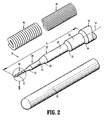
FIG. 2 is a perspective view with parts separated of the guidewire ofFIG. 1 illustrating the guide member, support coils and outer sheath; -
FIG. 3 is a perspective view of a portion of a leading end segment of the guide member of the guidewire ofFIGS. 1 and2 ; -
FIG. 4 is a plan view of a portion of the leading end segment of the guide member of the guidewire ofFIGS 1-3 ; -
FIG. 5 is an elevation view of a portion of the leading end segment of the guide member of the guidewire ofFIGS. 1-4 ; and -
FIG. 6 is a longitudinal cross-sectional view of the guidewire ofFIG. 2 ; -
FIG. 7 is a transverse cross-sectional view of the guidewire ofFIG. 6 taken along line 7-7; -
FIG. 8 is a transverse cross-sectional view of the guidewire ofFIG. 6 taken along line 8-8; -
FIG. 9 is a transverse cross-sectional view of the guidewire ofFIG. 6 taken along line 9-9; and -
FIGS. 10-12 are perspective views of the leading end segment of the guide member according to embodiments of the present disclosure. - In the following description, the terms "proximal" and "distal" as used herein refer to the relative position of the guidewire in a lumen. The "proximal" or "trailing" end of the guidewire is the guidewire segment extending outside the body closest to the clinician. The "distal" or "leading" end of the guidewire is the guidewire segment placed farthest into a body lumen from the entrance site.
- The guidewire of the present disclosure has particular application in a neurovascular procedure, but may be used in any interventional, diagnostic, and/or therapeutic procedure including coronary vascular, peripheral vascular, and gastro-intestinal applications in addition to a neurovascular application.
- In the figures below, the full length of the guidewire is not shown. The length of the guidewire can vary depending on the type of interventional procedure, though typically it ranges in length from 30 centimeters to 400 centimeters (cm). Common lengths of guidewires for coronary, peripheral and neurovascular procedures may range from 170 cm to 300 cm in length. These lengths permit the use of standardized rapid exchange or over-the-wire catheter systems. The length of the shaped distal end also may vary, for example, from about 5 cm to about 80 cm in length.
- In accordance with one application of the present disclosure, the maximum outer diameter of the guidewire ranges from about 0.02032cm (0.008 inches) to about 0.0457cm (0.018 inches), standard for guidewires used in a neurovascular procedure. The diameter of the guidewire may remain relatively constant over a major portion of the length of the guidewire; however, the leading or distal end incorporates a generally tapered or narrowed configuration to permit flexure while navigating the tortuous vasculature.
- The various embodiments of the disclosure will now be described in connection with the figures. It should be understood that for purposes of better describing the disclosure, the figures may not be to scale. Further, some of the figures include enlarged or distorted portions for the purpose of showing features that would not otherwise be apparent.
- Referring now to
FIG. 1 , a tortuous vasculature such as within the neurovascular space "n" is illustrated. For illustrative purposes, a tortuous path or a tortuous region within, e.g., the neurovascular space "n," includes large vasculature "V1" and smaller branch vessels "V2" which branch or extend from more proximal vessels at various angles, including up to 90 degrees or even greater than 90 degrees. - In
FIG. 1 , guidewire 10 of the present disclosure is illustrated as being positioned within a conventional access ormicrocatheter 100. Such microcatheters are known in the art. Commercially available microcatheters include Echelon™, Marathon™, and Nautica™ microcatheters sold by Tyco Healthcare Group LP dba Covidien, Irvine, CA. In general,microcatheter 100 includeshandle 102 andhollow catheter member 104 extending from thehandle 102.Microcatheter 100 defines a longitudinal opening extending at least throughcatheter member 104 for passage or reception ofguidewire 10. -
Guidewire 10 includesactuator 12 and guidemember 14 extending from theactuator 12.Actuator 12 may incorporate various features including handles, slides or the like, to facilitate handling and/or movement ofguide member 14. For example,actuator 12 may be used to translate and/or rotateguide member 14 during placement within the vasculature. - Referring now to
FIG. 2 ,guide member 14 ofguidewire 10 is illustrated and will be discussed in greater detail.Guide member 14 is dimensioned for insertion within the vasculature.Guide member 14 defines longitudinal axis "A" and has proximal or trailingend segment 16, and distal orleading end segment 18 forward of the trailingend segment 16. InFIG. 2 , a major longitudinal portion ofproximal end segment 16 is removed for ease of illustration. Trailingend segment 16 may be generally circular in cross-section with a length ranging from about 20 cm to about 240 cm, for example. Trailingend segment 16 may have a constant cross-sectional dimension or diameter along its length. With reference now toFIGS. 2-3 , leadingend segment 18 ofguide member 14 forms the working end or tip of theguidewire 10 and defines a reduced cross-sectional dimension relative to the cross-sectional dimension ofproximal end segment 16. The overall length "L" (FIG. 2 ) of leadingend segment 18 may range from about 20 cm to about 60 cm depending on the maximum diameter (e.g., the diameter of proximal end segment 16) and the overall length ofguidewire 10. Leadingend segment 18 may include a number of alternating tapered and annular segments which generally increase in cross-sectional dimension or diameter from the extreme remote or distal end toward the proximal end, i.e., towardproximal end segment 16. In the embodiment ofFIGS. 2-3 , leadingend segment 18 includes a distalremote segment 20, a firsttapered segment 22 extending proximally from distalremote segment 20 and coterminous therewith, a first generally annularsegment 24 extending from the firsttapered segment 22 and coterminous therewith, a secondtapered segment 26 extending from the first generally annularsegment 24 and coterminous therewith, and a second generally annularsegment 28 extending from the secondtapered segment 26 and being coterminous therewith. Leadingend segment 18 may further include a thirdtapered segment 30 extending contiguously from secondannular segment 28 and a thirdannular segment 32 which is coterminous with the thirdtapered segment 30. As a further alternative, leadingend segment 18 may also include a fourthtapered segment 34 extending from thirdannular segment 32 to leadingend segment 16. First, second and thirdannular segments FIGS. 7, 8 and 9 , respectively. Suitable diameters of each of annular first second and thirdannular segments Tapered segments Tapered segments Tapered segments - While the present disclosure identifies several
remote segments reference number 20 is intended to include eachremote segment fingers reference number 21 is intended to include each variation offinger 21. -
Remote segment 20 may define various configurations. In the embodiment ofFIGS. 2-6 and10-12 ,remote segment 20 is a flattened, planar or ribbon tip. However,remote segment 20 may define alternative cross-sectional shapes including circular, oval or the like. As a further alternative,remote segment 20 may be heat set into a variety of configurations including a linear arrangement. In one embodiment,remote segment 20 is heat set to maintain, e.g., a non-linear configuration such as a curve, by subjecting theremote segment 20 to heat at about 500°C to about 525°C for a duration of time ranging from about 30 seconds to about 2 minutes.Remote segment 20 may also be provided with a bent "j-hook" as is known in the art, or, may be bent into a "j-hook" design by the clinician prior to the interventional procedure. - With particular reference to
FIGS. 3-5 and10-12 ,remote segment 20 is shown including a plurality offingers 21. It is envisioned that the inclusion offingers 21 onremote segment 20 helps transmit torque applied byactuator 12 to leadingend segment 18, without significantly impacting the flexibility of leadingend segment 18. - In the embodiment illustrated in
FIGS. 3-5 , leadingend segment 18 ofguide member 14 includes a plurality offingers 21 thereon. Eachfinger 21 defines a first transverse dimension "FB" along a first transverse axis "B" (i.e., transverse to longitudinal axis "A"), a second transverse dimension "FC" along a second transverse axis "C" (i.e., transverse to longitudinal axis "A" and perpendicular to longitudinal axis "B"), and a longitudinal dimension "FA" along the longitudinal axis "A." Additionally, leadingend segment 18 defines a first transverse dimension "SB" along the first transverse axis "B," and a second transverse dimension "SC" along the second transverse axis "C." - In the embodiment illustrated in
FIGS. 3-5 ,remote segment 20 of leadingend segment 18 includes threefingers 21, which are all identically sized, shaped and axially spaced apart fromadjacent fingers 21. The present disclosure also contemplates more or fewer than three fingers 21 (e.g., two fingers as shown inFIGS. 11 and 12 ), andfingers 21 that differ in size, shape and/or spacing fromadjacent fingers 21. Additionally, whilefingers 21 are shown extending through a radial center ofremote segment 20 of leadingend segment 18, at least onefinger 21 may extend along anupper surface 19a or alower surface 19b ofremote segment 20. - Additionally, and as particularly shown in
FIGS. 2-4 and6 , first transverse dimension "FB" offinger 21 is greater than the corresponding first transverse dimension "SB" ofremote segment 20 of leading end segment 18 (i.e., the portion of leadingend segment 20 thatfinger 21 is in contact with). In disclosed embodiments, the distance "FB" is between about 0.00508cm (0.002 inches) and about 0.0106cm (0.004 inches), for example. It is also disclosed that the distance "SB" is between about 0.00254cm (0.001 inches) and about 0.00508cm (0.002 inches). Further, it is envisioned that the ratio between "FB" and "SB" is about 2:1. In disclosed embodiments, the distance "FA" is between about 0.00762cm (0.003 inches) and about 0.0127cm (0.005 inches), and the distances "FC" and "SC" are between about 0.00762cm (0.003 inches) and about 0.0127cm (0.005 inches). Further, it is envisioned that the distances "FC" and "SC" are equal to one another. It is further disclosed that a distance "AFA" betweenadjacent fingers 21 is between about 0.0254cm (0.010 inches) and about 0.0508cm (0.020 inches). Additionally, it is envisioned that a distal edge 23 of adistal-most finger 21 is between about 0.0254cm (0.010 inches) and about 0.0508cm (0.020 inches) from adistal-most tip 19 of leadingend segment 18. As can be appreciated, the distances provided herein are examples and are not intended to be limited to the disclosed ranges. - With reference to
FIGS. 10-12 , alternate embodiments ofremote segment 20 are shown, and are indicated byreference numbers FIG. 10 ,remote segment 20a includes threefingers 21a. As shown, the first transverse dimension "FB" of eachfinger 21a is greater than the corresponding first transverse dimension "SB" ofremote segment 20a of leading end segment 18 (i.e., the portion of leadingend segment 20a thatfinger 21a is in contact with). Additionally,fingers 21a only extend beyond onelateral edge 25 ofremote segment 20a;fingers 21a are flush withlateral edge 27. - Referring to
FIGS. 11 and 12 ,remote segments remote segment fingers finger remote segment fingers 21b extend beyondupper surface 19a andlower surface 19b (e.g., lateral surfaces) ofremote end segment 20b, andfingers 21c only extend beyondupper surface 19a ofremote segment 20c;fingers 21c are flush withlower surface 19b. - It is further envisioned that at least one
finger 21 and/orremote segment 20 includes a transverse cross-sectional shape other than the rectangular cross-sections shown. For instance,finger 21 and/orremote segment 20 of leadingend segment 18 can include any a circular, oval, or other polygon-shaped transverse cross-section. - A method of manufacturing a
surgical guidewire 10 is also disclosed. The method includes formingguide member 14 such thatguide wire 14 includes the features as described above. The disclosed methods include making leading end segment 18 (e.g., remote section 20) andfingers 21 of the same material (e.g., stainless steel, MP35N™ (a nickel-cobalt alloy), nitinol, or CoCr (a cobalt chromium alloy)), and include monolithically formingleading end segment 18 according to well known processes such as die stamping or micromachining (e.g., remote section 20) andfingers 21. It is also envisioned that leadingend segment 18 andfingers 21 are made of different materials. - With continued reference to
FIGS. 2 and6-8 , leadingend segment 18 further includes at least one coil coaxially mounted about at least a portion of theleading end segment 18, and is mounted withinouter sheath 42. In the embodiment, two coils are included, namely, first orproximal coil segment 44 and second ordistal coil segment 46 forward of theproximal coil segment 44.Proximal coil segment 44 may be fabricated from a number of suitable materials.Proximal coil segment 44 may be dimensioned to extend to encompass secondannular segment 28 and a portion of secondtapered segment 26. The diameter of the wire ofproximal coil segment 44 may range from about 0.002286cm (0.0009 inches) to about 0.00635cm (0.0025 inches), and, in one embodiment, is about 0.003048cm (0.0012 inches).Proximal coil segment 44 may also have a rectangular or flattened cross-section. -
Distal coil segment 46 extends fromproximal coil segment 44 and encompasses the remainder of leadingend segment 18 ofguide member 14.Distal coil segment 46 may be fabricated from a number of suitable materials, including, for example, stainless steel, MP35N™ (a nickel-cobalt alloy), nitinol, or CoCr (a cobalt chromium alloy). The wire ofdistal coil segment 46 has a diameter greater than the wire ofproximal coil segment 44. In one embodiment, the diameter ofdistal coil segment 46 ranges from about 0.003048cm (0.0012 inches) to about 0.00635cm (0.0025 inches), and may be about 0.00381cm (0.0015 inches).Distal coil segment 46 may also have a rectangular or flattened cross-section. The radiopacity ofdistal coil segment 46 may assist in placement of leadingend segment 18 within the vasculature through the use of imaging means, e.g., fluoroscopically during the interventional procedure. -
Proximal coil segment 44 anddistal coil segment 46 may provide lateral and/or torsional support to leadingend segment 18. In one embodiment, the lateral strength (or resistance to bending) ofdistal coil segment 46 is less than the lateral strength ofproximal coil segment 44 to permit flexing of adistal portion 38 of leadingend segment 18. The outer diameters of proximal anddistal coil segments annular segment 32 to provide a smooth transition. The configurations of proximal anddistal coil segments distal coil segments end segment 18 in differing or opposite directions. In embodiments, adjacent turns of the coils of each of proximal anddistal coil segments distal coil segments distal coil segments end segment 18 ofguide member 14 along various locations. Attachment may be effected though the use of adhesives, welding, soldering or the like.Distal coil segment 46 may be operatively connected or secured to leadingend segment 18 through a soldering process or with the use of an adhesive such as an epoxy, cyanoacrylate adhesive or an ultraviolet (UV) light curable adhesive. The soldering or adhesive element is represented schematically aselement 48 inFIG. 3 . -
Outer sheath 42 encloses leadingend segment 18, and proximal anddistal coil segments Outer sheath 42 may be fabricated from any suitable material, including, for example, polyurethanes, polyolefins, polyesters. In one embodiment,outer sheath 42 is a polyurethane sleeve which may or may not be loaded with tungsten, e.g., in microbead form. If loaded with tungsten,outer sheath 42 provides an additional element of radiopacity to leadingend segment 18 ofguide member 14.Outer sheath 42 may be thermoformed overleading end segment 18, and proximal anddistal coil segments Outer sheath 42 defines an atraumatic arcuateleading end surface 50 to minimize the potential of trauma or abrasion of the vessel walls. In one embodiment, the diameter ofouter sheath 42 is less than the diameter of proximal or trailingend segment 16 ofguide member 14 to provide a smooth transition between the components. - The Table provided below identifies ranges of dimensions of the components of the
leading end segment 18 for various guidewire sizes in accordance with the principles of the present disclosure. In the Table, D is represented as a percentage (%) of the diameter of the trailingend segment 16 and L represents the specific length of the component. For example, the diameter of firstannular segment 24 may range from about 10% to about 30% of the diameter of trailingend segment 16 and have a length ranging from about 2 cm to about 10 cm. All ranges are approximate. Preferred dimensions for the specific guidewire sizes may be at the midpoint of the specified ranges. Variations of these dimensions are envisioned.Table 1st Annular Segment 242nd Annular Segment 283rd Annular Segment 32 D (%) 10-30% 25-50% 50-90% L (cm) 2-10 5-30 10-30 - It is further envisioned that a lubricious coating may be disposed over components of
guide member 14 includingouter sheath 42. Suitable lubricious coatings include hydrophilic materials such as polyvinylpyrrolidone (PVP), polyethylene oxide, polyethylene glycol, cellulosic polymers, and hydrophilic maleic anhydride, or hydrophobic materials such as silicone, PTFE, or FEP. These coatings are typically applied by dip coating or spray methods, and heat curing may be used. For example, cure temperatures up to about 70 degrees C are used for silicone coatings, and several hundred degrees may be required for PTFE coatings. In addition to the lubricious coating, bioactive coatings may be applied over all or part of the guidewire. Such coatings also may incorporate materials such as heparin, hirudin and its analogs, or other drugs. These coatings typically are applied by dip coating. Bioactive coatings are desirable to prevent blood clotting or for delivery of drugs to a specific site. - The above description and the drawings are provided for the purpose of describing embodiments of the present disclosure and are not intended to limit the scope of the disclosure in any way. It will be apparent to those skilled in the art that various modifications and variations can be made without departing from the spirit or scope of the disclosure. Thus, it is intended that the present disclosure cover the modifications and variations of this disclosure provided they come within the scope of the appended claims and their equivalents.
Claims (19)
- A guidewire (10) comprising:an elongate guide member (14) dimensioned for insertion within a body vessel of a subject, the guide member (14) defining a longitudinal axis (A) and having trailing (16) and leading (18) end segments, the leading end segment (18) including a reduced cross-sectional dimension relative to a cross-sectional dimension of the trailing end segment (16), the leading end segment (18) including at least one finger (21) thereon, a first transverse dimension of the at least one finger (21) being greater than a corresponding first transverse dimension of the leading end segment (18) in contact therewith.
- The guidewire (10) according to claim 1 wherein the leading end segment (18) includes at least two fingers (21) axially spaced along the leading end.
- The guidewire (10) according to claim 2 wherein the two fingers (21) include a different transverse dimension from each other.
- The guidewire (10) according to any preceding claim wherein a second transverse dimension of the at least one finger (21) is substantially equal to a corresponding second transverse dimension of the leading end segment (18).
- The guidewire according to any preceding claim wherein the leading end segment (18) and the fingers (21) are made of the same material.
- The guidewire (10) according to any preceding claim wherein a length of each finger (21) along the first transverse axis (B) is between about 0.00508cm (0.002 inches) and about 0.0106cm (0.004 inches).
- The guidewire (10) according to claim 6 wherein a width of the leading end segment (18) along the first transverse axis (B) is between about 0.00254cm (0.001 inches) and about 0.00508cm (0.002 inches).
- The guidewire (10) according to claim 7 wherein the width of each finger (21) along the second transverse axis (C) is between about 0.00762cm (0.003 inches) and about 0.0127cm (0.005 inches).
- The guidewire (10) according to claim 6 wherein the leading end segment (18) includes at least two fingers (21) axially spaced along the leading end and wherein the distance between adjacent fingers (21) is between about 0.0254cm (0.010 inches) and about 0.0762cm (0.030 inches).
- The guidewire (10) according to any preceding claim wherein the ratio between a length of the finger (21) along the first transverse axis (B) and a width of the leading end segment (18) along the first transverse axis (B) is about 2:1.
- The guidewire (10) according to any preceding claim wherein the at least one finger (21) extends through a radial center of the leading end segment (18).
- The guidewire (10) according to any preceding claim wherein the leading end segment (18) defines a polygonal cross-section.
- The guidewire (10) according to claim 12 wherein the at least one finger (21) defines a polygonal cross-section.
- The guidewire (10) according to any preceding claim wherein a distal-most end (23) of the distal-most finger (21) is positioned proximally of a distal-most end (19) of the leading end segment (18).
- The guidewire (10) according to any preceding claim wherein the leading end segment (18) includes a pair of lateral sides (19a,19b) disposed parallel to the longitudinal axis (A), and wherein at least one finger (21) projects laterally beyond each of the lateral sides (19a,19b) of the leading end segment (18).
- The guidewire (10) according to any preceding claim wherein the leading end segment (18) and the fingers (21) are monolithically formed.
- The guidewire (10) according to any preceding claim further comprising an intermediate segment positioned between the leading end segment (18) and the trailing end segment (16), the intermediate segment having a cross-sectional dimension that is larger than the cross-sectional dimension of the leading end segment (18) and that is smaller than the cross-sectional dimension of the trailing end segment (16).
- A method for manufacturing a guidewire (10) dimensioned for insertion within a body vessel of a subject, the method comprising:forming a guide member (14) defining a longitudinal axis (A) and having trailing (16) and leading (18) end segments, the leading end segment (18) including a reduced cross-sectional dimension relative to a cross-sectional dimension of the trailing end segment (16), the leading end segment (18) including at least one finger (21) thereon, a first transverse dimension of the at least one finger (21) being greater than a corresponding first transverse dimension of the leading end segment (18) in contact therewith.
- The method of claim 18 wherein the leading end segment (18) and the at least one finger (21) are formed via stamping, or wherein the leading end segment (18) and the at least one finger (21) are formed via micro machining.
Applications Claiming Priority (1)
| Application Number | Priority Date | Filing Date | Title |
|---|---|---|---|
| US13/441,116 US8574170B2 (en) | 2012-04-06 | 2012-04-06 | Guidewire |
Publications (2)
| Publication Number | Publication Date |
|---|---|
| EP2647404A1 true EP2647404A1 (en) | 2013-10-09 |
| EP2647404B1 EP2647404B1 (en) | 2020-06-03 |
Family
ID=47826978
Family Applications (1)
| Application Number | Title | Priority Date | Filing Date |
|---|---|---|---|
| EP13157645.6A Active EP2647404B1 (en) | 2012-04-06 | 2013-03-04 | Guidewire |
Country Status (8)
| Country | Link |
|---|---|
| US (1) | US8574170B2 (en) |
| EP (1) | EP2647404B1 (en) |
| JP (1) | JP2013215566A (en) |
| KR (1) | KR20130114001A (en) |
| CN (1) | CN103357104B (en) |
| BR (1) | BR102013008346A2 (en) |
| CA (1) | CA2808726C (en) |
| RU (1) | RU2013110237A (en) |
Cited By (1)
| Publication number | Priority date | Publication date | Assignee | Title |
|---|---|---|---|---|
| EP4233971A3 (en) * | 2019-12-16 | 2023-10-18 | Stryker Corp. | Guidewires for medical devices |
Families Citing this family (6)
| Publication number | Priority date | Publication date | Assignee | Title |
|---|---|---|---|---|
| JP6534606B2 (en) * | 2015-11-26 | 2019-06-26 | 朝日インテック株式会社 | Guide wire |
| CN113181513B (en) * | 2016-03-10 | 2023-05-12 | 朝日英达科株式会社 | Guide wire |
| US10556287B2 (en) | 2017-02-21 | 2020-02-11 | Abbott Cardiovascular Systems Inc. | Method for selectively pretinning a guidewire core |
| GB201917184D0 (en) * | 2019-11-26 | 2020-01-08 | Univ Sheffield | Guiding device for a vascular catheter |
| US11944758B2 (en) * | 2019-12-16 | 2024-04-02 | Acclarent, Inc. | Atraumatic tip assembly for guidewire |
| US12178974B2 (en) | 2021-01-21 | 2024-12-31 | Abbott Cardiovascular Systems Inc. | Guidewire and method of use |
Citations (4)
| Publication number | Priority date | Publication date | Assignee | Title |
|---|---|---|---|---|
| US20090157050A1 (en) * | 2007-03-29 | 2009-06-18 | Terumo Kabushiki Kaisha | Guide wire |
| US20090312670A1 (en) * | 2008-06-13 | 2009-12-17 | Cook Incorporated | Wire guide having a rib for coil attachment |
| US20100036312A1 (en) * | 2008-06-08 | 2010-02-11 | Hotspur Technologies, Inc. | Apparatus and methods for removing obstructive material from body lumens |
| EP2316519A1 (en) * | 2009-10-27 | 2011-05-04 | PatentStra Co. Ltd. | A medical guide wire, a method of making the same, an assembly of microcatheter and guiding catheter combined with the medical guide wire |
Family Cites Families (31)
| Publication number | Priority date | Publication date | Assignee | Title |
|---|---|---|---|---|
| US4827941A (en) * | 1987-12-23 | 1989-05-09 | Advanced Cardiovascular Systems, Inc. | Extendable guidewire for cardiovascular procedures |
| US5238005A (en) * | 1991-11-18 | 1993-08-24 | Intelliwire, Inc. | Steerable catheter guidewire |
| US5243996A (en) * | 1992-01-03 | 1993-09-14 | Cook, Incorporated | Small-diameter superelastic wire guide |
| US5271415A (en) * | 1992-01-28 | 1993-12-21 | Baxter International Inc. | Guidewire extension system |
| US5769796A (en) | 1993-05-11 | 1998-06-23 | Target Therapeutics, Inc. | Super-elastic composite guidewire |
| US5409015A (en) | 1993-05-11 | 1995-04-25 | Target Therapeutics, Inc. | Deformable tip super elastic guidewire |
| US5406960A (en) * | 1994-04-13 | 1995-04-18 | Cordis Corporation | Guidewire with integral core and marker bands |
| US5636641A (en) | 1994-07-25 | 1997-06-10 | Advanced Cardiovascular Systems, Inc. | High strength member for intracorporeal use |
| US5664580A (en) * | 1995-01-31 | 1997-09-09 | Microvena Corporation | Guidewire having bimetallic coil |
| US6059738A (en) | 1995-06-30 | 2000-05-09 | Meadox Medicals, Inc. | Guidewire having a coated tip |
| WO1998055173A1 (en) * | 1997-06-04 | 1998-12-10 | Advanced Cardiovascular Systems, Inc. | Steerable guidewire with enhanced distal support |
| US6113557A (en) * | 1997-06-20 | 2000-09-05 | Medtronic Ave, Inc. | Variable stiffness angioplasty guide wire |
| US6387060B1 (en) | 1998-06-17 | 2002-05-14 | Advanced Cardiovascular Systems, Inc. | Composite radiopaque intracorporeal product |
| US6508803B1 (en) | 1998-11-06 | 2003-01-21 | Furukawa Techno Material Co., Ltd. | Niti-type medical guide wire and method of producing the same |
| US7717864B1 (en) | 1998-12-31 | 2010-05-18 | Advanced Cardiovascular Systems, Inc. | Composite guidewire with drawn and filled tube construction |
| US6602207B1 (en) | 2000-07-19 | 2003-08-05 | Scimed Life Systems, Inc. | Guide wire stiffness transition element |
| US20040064069A1 (en) * | 2002-09-30 | 2004-04-01 | Reynolds Brian R. | Medical device with support member |
| US7182735B2 (en) * | 2003-02-26 | 2007-02-27 | Scimed Life Systems, Inc. | Elongated intracorporal medical device |
| US7540845B2 (en) | 2003-09-05 | 2009-06-02 | Boston Scientific Scimed, Inc | Medical device coil |
| US7371248B2 (en) * | 2003-10-14 | 2008-05-13 | Medtronic Vascular, Inc. | Steerable distal protection guidewire and methods of use |
| JP3626488B1 (en) * | 2004-03-15 | 2005-03-09 | 朝日インテック株式会社 | Medical guidewire |
| JP3694312B1 (en) * | 2005-01-26 | 2005-09-14 | 朝日インテック株式会社 | Medical guidewire |
| JP2006271955A (en) * | 2005-03-02 | 2006-10-12 | Terumo Corp | Guide wire |
| EP1906888A1 (en) * | 2005-05-24 | 2008-04-09 | Abbott Laboratories | Bifurcation stent delivery catheter assembly and method |
| US20070167972A1 (en) * | 2006-01-17 | 2007-07-19 | Euteneuer Charles L | Balloon apparatus and methods |
| US20070167876A1 (en) * | 2006-01-17 | 2007-07-19 | Euteneuer Charles L | Occluding guidewire and methods |
| JP5020630B2 (en) | 2006-12-28 | 2012-09-05 | テルモ株式会社 | Guide wire |
| JP4981471B2 (en) | 2007-02-09 | 2012-07-18 | テルモ株式会社 | Guide wire |
| US9034007B2 (en) * | 2007-09-21 | 2015-05-19 | Insera Therapeutics, Inc. | Distal embolic protection devices with a variable thickness microguidewire and methods for their use |
| CN102753231B (en) * | 2010-02-05 | 2015-07-15 | 泰尔茂株式会社 | Guide wire |
| WO2012141920A1 (en) * | 2011-04-12 | 2012-10-18 | Boston Scientific Scimed, Inc. | Balloon catheter |
-
2012
- 2012-04-06 US US13/441,116 patent/US8574170B2/en active Active
-
2013
- 2013-03-04 EP EP13157645.6A patent/EP2647404B1/en active Active
- 2013-03-05 CA CA2808726A patent/CA2808726C/en active Active
- 2013-03-07 RU RU2013110237/14A patent/RU2013110237A/en not_active Application Discontinuation
- 2013-03-19 JP JP2013056396A patent/JP2013215566A/en active Pending
- 2013-04-03 CN CN201310113923.3A patent/CN103357104B/en active Active
- 2013-04-05 BR BR102013008346A patent/BR102013008346A2/en not_active Application Discontinuation
- 2013-04-05 KR KR1020130037315A patent/KR20130114001A/en not_active Ceased
Patent Citations (4)
| Publication number | Priority date | Publication date | Assignee | Title |
|---|---|---|---|---|
| US20090157050A1 (en) * | 2007-03-29 | 2009-06-18 | Terumo Kabushiki Kaisha | Guide wire |
| US20100036312A1 (en) * | 2008-06-08 | 2010-02-11 | Hotspur Technologies, Inc. | Apparatus and methods for removing obstructive material from body lumens |
| US20090312670A1 (en) * | 2008-06-13 | 2009-12-17 | Cook Incorporated | Wire guide having a rib for coil attachment |
| EP2316519A1 (en) * | 2009-10-27 | 2011-05-04 | PatentStra Co. Ltd. | A medical guide wire, a method of making the same, an assembly of microcatheter and guiding catheter combined with the medical guide wire |
Cited By (2)
| Publication number | Priority date | Publication date | Assignee | Title |
|---|---|---|---|---|
| EP4233971A3 (en) * | 2019-12-16 | 2023-10-18 | Stryker Corp. | Guidewires for medical devices |
| US12005205B2 (en) | 2019-12-16 | 2024-06-11 | Stryker Corporation | Guidewires for medical devices |
Also Published As
| Publication number | Publication date |
|---|---|
| US8574170B2 (en) | 2013-11-05 |
| EP2647404B1 (en) | 2020-06-03 |
| US20130267934A1 (en) | 2013-10-10 |
| CN103357104A (en) | 2013-10-23 |
| KR20130114001A (en) | 2013-10-16 |
| RU2013110237A (en) | 2014-09-20 |
| CN103357104B (en) | 2016-08-17 |
| CA2808726A1 (en) | 2013-10-06 |
| JP2013215566A (en) | 2013-10-24 |
| BR102013008346A2 (en) | 2016-01-26 |
| CA2808726C (en) | 2015-09-15 |
Similar Documents
| Publication | Publication Date | Title |
|---|---|---|
| CA2806985C (en) | Intravascular guidewire | |
| EP2647404B1 (en) | Guidewire | |
| JP6179995B2 (en) | Reinforced stretch medical device and manufacturing method | |
| EP1804882B1 (en) | Catheter with a pre-shaped distal tip | |
| US20170367712A1 (en) | Stretch-resistant coil | |
| EP2391417B1 (en) | Guidewire | |
| US7993285B2 (en) | Medical device having flexible distal tip | |
| EP1195174A1 (en) | A guide wire, and a method to advance a guide wire along a path | |
| US20130296831A1 (en) | Guide wire with soldered multilayer coil member | |
| EP2692390B1 (en) | Guidewire | |
| US20090312670A1 (en) | Wire guide having a rib for coil attachment | |
| JP5473677B2 (en) | Guide wire | |
| KR20260012724A (en) | Intravascular device with nested hypotube configuration | |
| WO2024137941A2 (en) | Uniform outer diameter guidewire devices | |
| US20170120018A1 (en) | Guidewire | |
| CN109069804B (en) | guide wire |
Legal Events
| Date | Code | Title | Description |
|---|---|---|---|
| PUAI | Public reference made under article 153(3) epc to a published international application that has entered the european phase |
Free format text: ORIGINAL CODE: 0009012 |
|
| 17P | Request for examination filed |
Effective date: 20130304 |
|
| AK | Designated contracting states |
Kind code of ref document: A1 Designated state(s): AL AT BE BG CH CY CZ DE DK EE ES FI FR GB GR HR HU IE IS IT LI LT LU LV MC MK MT NL NO PL PT RO RS SE SI SK SM TR |
|
| AX | Request for extension of the european patent |
Extension state: BA ME |
|
| 17Q | First examination report despatched |
Effective date: 20140407 |
|
| STAA | Information on the status of an ep patent application or granted ep patent |
Free format text: STATUS: EXAMINATION IS IN PROGRESS |
|
| GRAP | Despatch of communication of intention to grant a patent |
Free format text: ORIGINAL CODE: EPIDOSNIGR1 |
|
| STAA | Information on the status of an ep patent application or granted ep patent |
Free format text: STATUS: GRANT OF PATENT IS INTENDED |
|
| INTG | Intention to grant announced |
Effective date: 20200109 |
|
| GRAS | Grant fee paid |
Free format text: ORIGINAL CODE: EPIDOSNIGR3 |
|
| GRAA | (expected) grant |
Free format text: ORIGINAL CODE: 0009210 |
|
| STAA | Information on the status of an ep patent application or granted ep patent |
Free format text: STATUS: THE PATENT HAS BEEN GRANTED |
|
| AK | Designated contracting states |
Kind code of ref document: B1 Designated state(s): AL AT BE BG CH CY CZ DE DK EE ES FI FR GB GR HR HU IE IS IT LI LT LU LV MC MK MT NL NO PL PT RO RS SE SI SK SM TR |
|
| REG | Reference to a national code |
Ref country code: GB Ref legal event code: FG4D |
|
| REG | Reference to a national code |
Ref country code: AT Ref legal event code: REF Ref document number: 1276357 Country of ref document: AT Kind code of ref document: T Effective date: 20200615 Ref country code: CH Ref legal event code: EP |
|
| REG | Reference to a national code |
Ref country code: DE Ref legal event code: R096 Ref document number: 602013069555 Country of ref document: DE |
|
| REG | Reference to a national code |
Ref country code: LT Ref legal event code: MG4D |
|
| PG25 | Lapsed in a contracting state [announced via postgrant information from national office to epo] |
Ref country code: FI Free format text: LAPSE BECAUSE OF FAILURE TO SUBMIT A TRANSLATION OF THE DESCRIPTION OR TO PAY THE FEE WITHIN THE PRESCRIBED TIME-LIMIT Effective date: 20200603 Ref country code: GR Free format text: LAPSE BECAUSE OF FAILURE TO SUBMIT A TRANSLATION OF THE DESCRIPTION OR TO PAY THE FEE WITHIN THE PRESCRIBED TIME-LIMIT Effective date: 20200904 Ref country code: NO Free format text: LAPSE BECAUSE OF FAILURE TO SUBMIT A TRANSLATION OF THE DESCRIPTION OR TO PAY THE FEE WITHIN THE PRESCRIBED TIME-LIMIT Effective date: 20200903 Ref country code: SE Free format text: LAPSE BECAUSE OF FAILURE TO SUBMIT A TRANSLATION OF THE DESCRIPTION OR TO PAY THE FEE WITHIN THE PRESCRIBED TIME-LIMIT Effective date: 20200603 Ref country code: LT Free format text: LAPSE BECAUSE OF FAILURE TO SUBMIT A TRANSLATION OF THE DESCRIPTION OR TO PAY THE FEE WITHIN THE PRESCRIBED TIME-LIMIT Effective date: 20200603 |
|
| REG | Reference to a national code |
Ref country code: NL Ref legal event code: MP Effective date: 20200603 |
|
| PG25 | Lapsed in a contracting state [announced via postgrant information from national office to epo] |
Ref country code: BG Free format text: LAPSE BECAUSE OF FAILURE TO SUBMIT A TRANSLATION OF THE DESCRIPTION OR TO PAY THE FEE WITHIN THE PRESCRIBED TIME-LIMIT Effective date: 20200903 Ref country code: RS Free format text: LAPSE BECAUSE OF FAILURE TO SUBMIT A TRANSLATION OF THE DESCRIPTION OR TO PAY THE FEE WITHIN THE PRESCRIBED TIME-LIMIT Effective date: 20200603 Ref country code: HR Free format text: LAPSE BECAUSE OF FAILURE TO SUBMIT A TRANSLATION OF THE DESCRIPTION OR TO PAY THE FEE WITHIN THE PRESCRIBED TIME-LIMIT Effective date: 20200603 Ref country code: LV Free format text: LAPSE BECAUSE OF FAILURE TO SUBMIT A TRANSLATION OF THE DESCRIPTION OR TO PAY THE FEE WITHIN THE PRESCRIBED TIME-LIMIT Effective date: 20200603 |
|
| REG | Reference to a national code |
Ref country code: AT Ref legal event code: MK05 Ref document number: 1276357 Country of ref document: AT Kind code of ref document: T Effective date: 20200603 |
|
| PG25 | Lapsed in a contracting state [announced via postgrant information from national office to epo] |
Ref country code: NL Free format text: LAPSE BECAUSE OF FAILURE TO SUBMIT A TRANSLATION OF THE DESCRIPTION OR TO PAY THE FEE WITHIN THE PRESCRIBED TIME-LIMIT Effective date: 20200603 Ref country code: AL Free format text: LAPSE BECAUSE OF FAILURE TO SUBMIT A TRANSLATION OF THE DESCRIPTION OR TO PAY THE FEE WITHIN THE PRESCRIBED TIME-LIMIT Effective date: 20200603 |
|
| PG25 | Lapsed in a contracting state [announced via postgrant information from national office to epo] |
Ref country code: IT Free format text: LAPSE BECAUSE OF FAILURE TO SUBMIT A TRANSLATION OF THE DESCRIPTION OR TO PAY THE FEE WITHIN THE PRESCRIBED TIME-LIMIT Effective date: 20200603 Ref country code: AT Free format text: LAPSE BECAUSE OF FAILURE TO SUBMIT A TRANSLATION OF THE DESCRIPTION OR TO PAY THE FEE WITHIN THE PRESCRIBED TIME-LIMIT Effective date: 20200603 Ref country code: EE Free format text: LAPSE BECAUSE OF FAILURE TO SUBMIT A TRANSLATION OF THE DESCRIPTION OR TO PAY THE FEE WITHIN THE PRESCRIBED TIME-LIMIT Effective date: 20200603 Ref country code: SM Free format text: LAPSE BECAUSE OF FAILURE TO SUBMIT A TRANSLATION OF THE DESCRIPTION OR TO PAY THE FEE WITHIN THE PRESCRIBED TIME-LIMIT Effective date: 20200603 Ref country code: ES Free format text: LAPSE BECAUSE OF FAILURE TO SUBMIT A TRANSLATION OF THE DESCRIPTION OR TO PAY THE FEE WITHIN THE PRESCRIBED TIME-LIMIT Effective date: 20200603 Ref country code: PT Free format text: LAPSE BECAUSE OF FAILURE TO SUBMIT A TRANSLATION OF THE DESCRIPTION OR TO PAY THE FEE WITHIN THE PRESCRIBED TIME-LIMIT Effective date: 20201006 Ref country code: RO Free format text: LAPSE BECAUSE OF FAILURE TO SUBMIT A TRANSLATION OF THE DESCRIPTION OR TO PAY THE FEE WITHIN THE PRESCRIBED TIME-LIMIT Effective date: 20200603 Ref country code: CZ Free format text: LAPSE BECAUSE OF FAILURE TO SUBMIT A TRANSLATION OF THE DESCRIPTION OR TO PAY THE FEE WITHIN THE PRESCRIBED TIME-LIMIT Effective date: 20200603 |
|
| PG25 | Lapsed in a contracting state [announced via postgrant information from national office to epo] |
Ref country code: IS Free format text: LAPSE BECAUSE OF FAILURE TO SUBMIT A TRANSLATION OF THE DESCRIPTION OR TO PAY THE FEE WITHIN THE PRESCRIBED TIME-LIMIT Effective date: 20201003 Ref country code: SK Free format text: LAPSE BECAUSE OF FAILURE TO SUBMIT A TRANSLATION OF THE DESCRIPTION OR TO PAY THE FEE WITHIN THE PRESCRIBED TIME-LIMIT Effective date: 20200603 Ref country code: PL Free format text: LAPSE BECAUSE OF FAILURE TO SUBMIT A TRANSLATION OF THE DESCRIPTION OR TO PAY THE FEE WITHIN THE PRESCRIBED TIME-LIMIT Effective date: 20200603 |
|
| REG | Reference to a national code |
Ref country code: DE Ref legal event code: R097 Ref document number: 602013069555 Country of ref document: DE |
|
| PLBE | No opposition filed within time limit |
Free format text: ORIGINAL CODE: 0009261 |
|
| STAA | Information on the status of an ep patent application or granted ep patent |
Free format text: STATUS: NO OPPOSITION FILED WITHIN TIME LIMIT |
|
| PG25 | Lapsed in a contracting state [announced via postgrant information from national office to epo] |
Ref country code: DK Free format text: LAPSE BECAUSE OF FAILURE TO SUBMIT A TRANSLATION OF THE DESCRIPTION OR TO PAY THE FEE WITHIN THE PRESCRIBED TIME-LIMIT Effective date: 20200603 |
|
| 26N | No opposition filed |
Effective date: 20210304 |
|
| PG25 | Lapsed in a contracting state [announced via postgrant information from national office to epo] |
Ref country code: SI Free format text: LAPSE BECAUSE OF FAILURE TO SUBMIT A TRANSLATION OF THE DESCRIPTION OR TO PAY THE FEE WITHIN THE PRESCRIBED TIME-LIMIT Effective date: 20200603 |
|
| PG25 | Lapsed in a contracting state [announced via postgrant information from national office to epo] |
Ref country code: MC Free format text: LAPSE BECAUSE OF FAILURE TO SUBMIT A TRANSLATION OF THE DESCRIPTION OR TO PAY THE FEE WITHIN THE PRESCRIBED TIME-LIMIT Effective date: 20200603 |
|
| REG | Reference to a national code |
Ref country code: CH Ref legal event code: PL |
|
| GBPC | Gb: european patent ceased through non-payment of renewal fee |
Effective date: 20210304 |
|
| REG | Reference to a national code |
Ref country code: BE Ref legal event code: MM Effective date: 20210331 |
|
| PG25 | Lapsed in a contracting state [announced via postgrant information from national office to epo] |
Ref country code: CH Free format text: LAPSE BECAUSE OF NON-PAYMENT OF DUE FEES Effective date: 20210331 Ref country code: LI Free format text: LAPSE BECAUSE OF NON-PAYMENT OF DUE FEES Effective date: 20210331 Ref country code: LU Free format text: LAPSE BECAUSE OF NON-PAYMENT OF DUE FEES Effective date: 20210304 Ref country code: GB Free format text: LAPSE BECAUSE OF NON-PAYMENT OF DUE FEES Effective date: 20210304 Ref country code: IE Free format text: LAPSE BECAUSE OF NON-PAYMENT OF DUE FEES Effective date: 20210304 |
|
| PG25 | Lapsed in a contracting state [announced via postgrant information from national office to epo] |
Ref country code: BE Free format text: LAPSE BECAUSE OF NON-PAYMENT OF DUE FEES Effective date: 20210331 |
|
| PG25 | Lapsed in a contracting state [announced via postgrant information from national office to epo] |
Ref country code: HU Free format text: LAPSE BECAUSE OF FAILURE TO SUBMIT A TRANSLATION OF THE DESCRIPTION OR TO PAY THE FEE WITHIN THE PRESCRIBED TIME-LIMIT; INVALID AB INITIO Effective date: 20130304 |
|
| PG25 | Lapsed in a contracting state [announced via postgrant information from national office to epo] |
Ref country code: CY Free format text: LAPSE BECAUSE OF FAILURE TO SUBMIT A TRANSLATION OF THE DESCRIPTION OR TO PAY THE FEE WITHIN THE PRESCRIBED TIME-LIMIT Effective date: 20200603 |
|
| PG25 | Lapsed in a contracting state [announced via postgrant information from national office to epo] |
Ref country code: MK Free format text: LAPSE BECAUSE OF FAILURE TO SUBMIT A TRANSLATION OF THE DESCRIPTION OR TO PAY THE FEE WITHIN THE PRESCRIBED TIME-LIMIT Effective date: 20200603 |
|
| PG25 | Lapsed in a contracting state [announced via postgrant information from national office to epo] |
Ref country code: TR Free format text: LAPSE BECAUSE OF FAILURE TO SUBMIT A TRANSLATION OF THE DESCRIPTION OR TO PAY THE FEE WITHIN THE PRESCRIBED TIME-LIMIT Effective date: 20200603 |
|
| PG25 | Lapsed in a contracting state [announced via postgrant information from national office to epo] |
Ref country code: MT Free format text: LAPSE BECAUSE OF FAILURE TO SUBMIT A TRANSLATION OF THE DESCRIPTION OR TO PAY THE FEE WITHIN THE PRESCRIBED TIME-LIMIT Effective date: 20200603 |
|
| PGFP | Annual fee paid to national office [announced via postgrant information from national office to epo] |
Ref country code: DE Payment date: 20260219 Year of fee payment: 14 |
|
| PGFP | Annual fee paid to national office [announced via postgrant information from national office to epo] |
Ref country code: FR Payment date: 20260219 Year of fee payment: 14 |