EP2647328A1 - Antenna device - Google Patents
Antenna device Download PDFInfo
- Publication number
- EP2647328A1 EP2647328A1 EP11845678.9A EP11845678A EP2647328A1 EP 2647328 A1 EP2647328 A1 EP 2647328A1 EP 11845678 A EP11845678 A EP 11845678A EP 2647328 A1 EP2647328 A1 EP 2647328A1
- Authority
- EP
- European Patent Office
- Prior art keywords
- receiving antenna
- receiving
- antenna
- antennas
- reference point
- Prior art date
- Legal status (The legal status is an assumption and is not a legal conclusion. Google has not performed a legal analysis and makes no representation as to the accuracy of the status listed.)
- Granted
Links
Images




Classifications
-
- A—HUMAN NECESSITIES
- A61—MEDICAL OR VETERINARY SCIENCE; HYGIENE
- A61B—DIAGNOSIS; SURGERY; IDENTIFICATION
- A61B1/00—Instruments for performing medical examinations of the interior of cavities or tubes of the body by visual or photographical inspection, e.g. endoscopes; Illuminating arrangements therefor
- A61B1/00002—Operational features of endoscopes
- A61B1/00011—Operational features of endoscopes characterised by signal transmission
- A61B1/00016—Operational features of endoscopes characterised by signal transmission using wireless means
-
- A—HUMAN NECESSITIES
- A61—MEDICAL OR VETERINARY SCIENCE; HYGIENE
- A61B—DIAGNOSIS; SURGERY; IDENTIFICATION
- A61B5/00—Measuring for diagnostic purposes; Identification of persons
- A61B5/07—Endoradiosondes
-
- H—ELECTRICITY
- H01—ELECTRIC ELEMENTS
- H01Q—ANTENNAS, i.e. RADIO AERIALS
- H01Q21/00—Antenna arrays or systems
- H01Q21/24—Combinations of antenna units polarised in different directions for transmitting or receiving circularly and elliptically polarised waves or waves linearly polarised in any direction
-
- A—HUMAN NECESSITIES
- A61—MEDICAL OR VETERINARY SCIENCE; HYGIENE
- A61B—DIAGNOSIS; SURGERY; IDENTIFICATION
- A61B1/00—Instruments for performing medical examinations of the interior of cavities or tubes of the body by visual or photographical inspection, e.g. endoscopes; Illuminating arrangements therefor
- A61B1/04—Instruments for performing medical examinations of the interior of cavities or tubes of the body by visual or photographical inspection, e.g. endoscopes; Illuminating arrangements therefor combined with photographic or television appliances
- A61B1/041—Capsule endoscopes for imaging
-
- H—ELECTRICITY
- H01—ELECTRIC ELEMENTS
- H01Q—ANTENNAS, i.e. RADIO AERIALS
- H01Q1/00—Details of, or arrangements associated with, antennas
- H01Q1/27—Adaptation for use in or on movable bodies
- H01Q1/273—Adaptation for carrying or wearing by persons or animals
-
- H—ELECTRICITY
- H01—ELECTRIC ELEMENTS
- H01Q—ANTENNAS, i.e. RADIO AERIALS
- H01Q1/00—Details of, or arrangements associated with, antennas
- H01Q1/36—Structural form of radiating elements, e.g. cone, spiral, umbrella; Particular materials used therewith
- H01Q1/38—Structural form of radiating elements, e.g. cone, spiral, umbrella; Particular materials used therewith formed by a conductive layer on an insulating support
-
- H—ELECTRICITY
- H01—ELECTRIC ELEMENTS
- H01Q—ANTENNAS, i.e. RADIO AERIALS
- H01Q9/00—Electrically-short antennas having dimensions not more than twice the operating wavelength and consisting of conductive active radiating elements
- H01Q9/04—Resonant antennas
- H01Q9/16—Resonant antennas with feed intermediate between the extremities of the antenna, e.g. centre-fed dipole
- H01Q9/28—Conical, cylindrical, cage, strip, gauze, or like elements having an extended radiating surface; Elements comprising two conical surfaces having collinear axes and adjacent apices and fed by two-conductor transmission lines
- H01Q9/285—Planar dipole
Definitions
- the present invention relates to a receiving antenna apparatus that receives a radio signal transmitted from a capsule endoscope inside of a subject.
- a capsule endoscope with a built-in imaging function and a radio communication function which are provided in a capsule-shaped casing formed to a size that can be introduced into the gut of a subject such as a patient.
- the capsule endoscope is first swallowed from the mouth of the subject and then it moves in the inside of the subject such as the gut by peristaltic movement and the like. Then, it sequentially captures images of the inside of the subject to generate image data, and sequentially transmits the image data.
- the image data thus transmitted from the capsule endoscope by wireless transmission is received by a receiving apparatus through a receiving antenna provided outside the subject.
- the receiving apparatus stores the image data received through the receiving antenna in a built-in memory.
- the subject can freely act during a period until the capsule endoscope is excreted after the capsule endoscope is swallowed, by carrying the receiving apparatus that has a radio communication function and a memory function.
- a practitioner such as a doctor puts the image data accumulated in the memory of the receiving apparatus in an image display apparatus so that images of the inside of the subject which correspond to the images obtained by the capsule endoscope, that is, the internal organs' images are displayed on a display of the image display apparatus.
- the practitioner observes the images of the internal organs and the like displayed on the display, and diagnoses the subject.
- a typical receiving apparatus In receiving the radio signal transmitted from the capsule endoscope, a typical receiving apparatus has a plurality of receiving antennas arranged in a dispersed manner outside the subject, selects one antenna with the strongest received strength, and receives the radio signal by the selected antenna.
- a known receiving apparatus in which reception switching among a plurality of antennas placed outside a subject is performed and which detects the position of a capsule endoscope in the subject that is the source of a radio signal based on the field strength received by each antenna (See Patent Literature 1).
- the present invention has been achieved in view of the foregoing and an object of the present invention is to provide an antenna apparatus that can receive a radio signal transmitted from a capsule endoscope introduced in an inside of a subject precisely.
- an antenna apparatus includes: a first receiving antenna and a second receiving antenna respectively disposed at positions on a plane which are in an equal distance from a reference point and face each other with the reference point therebetween; a third receiving antenna and a fourth receiving antenna disposed at positions on the plane, a gravity center of the third receiving antenna and a gravity center of the fourth receiving antenna being in an equal distance from the reference point on the plane, a straight line connecting the gravity centers of the third receiving antenna and the fourth receiving antenna being at an angle of 90 degrees with respect to a straight line connecting a gravity center of the first receiving antenna and a gravity center of the second receiving antenna; and a fifth receiving antenna, a sixth receiving antenna, a seventh receiving antenna, and an eighth receiving antenna disposed respectively at positions on the plane, gravity centers of the fifth to eighth receiving antennas being on straight lines different from each other, which are rotated by an angle of 45 degrees from the straight line connecting the gravity centers of the first receiving antenna and the second
- the first to fourth receiving antennas are disposed respectively at positions which are in an equal distance from the reference point within the plane.
- the third and fourth receiving antennas are in an equal distance from the reference point and are disposed, with respect to the reference point, closer to outer peripheries of the plane than the first and second receiving antennas.
- the first to eighth receiving antennas are balanced antennas exhibiting a larger loss in cross polarization than in main polarization.
- the first to eighth receiving antennas are dipole antennas each of which has two linear elements, the two linear elements being arranged in a straight line.
- the first to eighth receiving antennas are provided with first to eighth active circuits, respectively.
- the first to eighth receiving antennas are disposed on one plate unit.
- the third and fourth receiving antennas are disposed on outer peripheries of the plate unit.
- the antenna apparatus further includes first to eighth transmission lines to transmit and receive a signal to and from the first to eighth receiving antennas, respectively, and wherein the first to eighth transmission lines gather at an end portion of the plate unit.
- the plate unit includes a positioning unit that positions the antenna apparatus with respect to a target object to which the antenna apparatus is mounted.
- An antenna apparatus includes: first and second receiving antennas respectively disposed at positions on a plane which are in an equal distance from a reference point and face each other with the reference point therebetween; third and fourth receiving antennas disposed at positions on the plane, a gravity center of the third receiving antenna and a gravity center of the fourth receiving antenna being in an equal distance from the reference point on the plane, a straight line connecting the gravity centers of the third and fourth receiving antennas being at an angle of 90 degrees with respect to a straight line connecting gravity centers of the first and second receiving antennas; and a fifth receiving antenna, a sixth receiving antenna, a seventh receiving antenna, and an eighth receiving antenna disposed respectively at positions on the plane, gravity centers of the fifth to eighth receiving antennas being on straight lines different from each other, which are rotated by an angle of 45 degrees from the straight line connecting the gravity centers of the first and second receiving antennas and the straight line connecting the gravity centers of the third and fourth receiving antennas, respectively.
- a capsule endoscope system including a capsule endoscope which is introduced into the inside of a subject to capture in-vivo images of the subject, is presented as an example of an antenna apparatus according the present invention.
- the present invention is not limited by this embodiment.
- a capsule endoscope system 1 includes a capsule endoscope 3 that captures an in-vivo image of a subject 2, an antenna apparatus 4 that receives a radio signal transmitted from the capsule endoscope 3 introduced in the subject 2, a receiving apparatus 5 that performs predetermined processing on the radio signal input from the antenna apparatus 4 and stores the processing result, and an image display apparatus 6 that displays an image corresponding to image data of the inside of the subject 2 captured by the capsule endoscope 3.
- the capsule endoscope 3 has an imaging function to capture an image of the inside of the subject 2, and a radio communication function to transmit image data obtained by capturing an image of the inside of the subject 2 to the receiving apparatus 5.
- the capsule endoscope 3 is swallowed by the subject 2 so that it passes through the esophagus of the subject 2 and moves in the body cavity of the subject by peristaltic movement of the lumen of the gut.
- the capsule endoscope 3 sequentially captures images of the body cavity of the subject 2 at intervals of a minute time, for example, an interval of 0.5 seconds while moving in the body cavity, and sequentially generates and transmits image data of the captured images of the inside of the subject 2 to the receiving apparatus 5.
- the capsule endoscope 3 generates a transmission signal, which includes the image data and received-field-strength detection data including position information (beacon) etc. which makes received field strength easy to be detected, and transmits a radio signal obtained by modulating the generated transmission signal to the receiving apparatus 5 by wireless transmission.
- the antenna apparatus 4 outputs the radio signal, received from the capsule endoscope 3, to the receiving apparatus 5 through an antenna cable 51.
- the antenna apparatus 4 is fixed to the subject 2 with a belt or the like during the examination.
- the receiving apparatus 5 acquires the radio signal, which is transmitted from the capsule endoscope 3 by wireless transmission, through the antenna apparatus 4 and the antenna cable 51.
- the receiving apparatus 5 acquires the image data of the inside of the subject 2 based on the radio signal received from the capsule endoscope 3.
- the receiving apparatus 5 stores received-field-strength information and time information which indicates a time point in association with the received image data.
- the receiving apparatus 5 is carried by the subject 2 while the capsule endoscope 3 is capturing images, that is, during a period from when the endoscope is introduced from the mount of the subject 2 and to when the endoscope passes through the gut and is finally excreted out of the subject 2. After the examination using the capsule endoscope 3 ends, the receiving apparatus 5 is removed from the subject 2 and is then connected to the image display apparatus 6 so that information on the image, data etc. received from the capsule endoscope 3 can be transmitted.
- the image display apparatus 6 is configured by a work station or a personal computer including a display such as a liquid crystal display.
- the image display apparatus 6 displays an image corresponding to the image data in the subject 2 acquired by the receiving apparatus 5.
- a cradle 6a that reads the image data from the memory of the receiving apparatus 5 and an operation input devices 6b such as a keyboard and a mouse are connected to the image display apparatus 6.
- the cradle 6a acquires image data, the received-field-strength information associated with the image data, time information, and relevant information such as identification information of the capsule endoscope 3, from the memory of the receiving apparatus 5 when the receiving apparatus 5 is mounted, and transmits the acquired various information to the image display apparatus 6.
- the operation input device 6b accepts the input from the user.
- the user observes living body parts in the subject 2, for example, the esophagus, the stomach, the small intestine, and the large intestine, and makes a diagnosis on the subject 2 while operating the operation input device 6b and viewing the images of the inside of the subject 2 which are sequentially displayed by the image display apparatus 6.
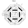
- FIG. 2 is a plan view that illustrates a schematic configuration of the antenna apparatus 4.
- the antenna apparatus 4 includes a plate unit 40, a first receiving antenna 41, a second receiving antenna 42, a third receiving antenna 43, a fourth receiving antenna 44, a fifth receiving antenna 45, a sixth receiving antenna 46, a seventh receiving antenna 47, an eighth receiving antenna 48, and a connector 49.
- the first to eighth receiving antennas 41 to 48 are provided on one plate unit 40.
- the plate unit 40 is formed of a sheet-like flexible substrate.
- the principal surface of the plate unit 40 is substantially octagonal.
- the plate unit 40 is formed to a size that can cover the entire surface of the abdomen of the subject 2, for example, 200 mm in length x 200 mm in width.
- the plate unit 40 has an opening 40a.
- the opening 40a is formed such that the center is coincident with a reference point O 1 of the plate unit 40.
- the opening 40a functions as a positioning unit which positions the antenna apparatus with respect to the subject 2 when the antenna apparatus is attached to the subject 2.
- the opening 40a may be formed using a transparent member, for example, a transparent vinyl sheet, etc.
- the principal surface of the plate unit 40 does not necessarily have a substantial octagonal shape, but may have a rectangular shape, etc.
- the first receiving antenna 41 and the second receiving antenna 42 are disposed at positions which face each another with the reference point O 1 therebetween.
- the first receiving antenna 41 and the second receiving antenna 42 are disposed at positions which are in an equal distance from the reference point O 1 .
- the first receiving antenna 41 and the second receiving antenna 42 are disposed respectively at the positions on the plate unit 40 which are in a distance of r 1 from the reference point O 1 .
- an element 41a and an element 42a thereof are formed on the plate unit 40 as printed circuits.
- the first receiving antenna 41 and the second receiving antenna 42 include an active circuit 41b and an active circuit 42b connected to the element 41a and the element 42a, respectively.
- the active circuits 41b and 42b are both formed on the plate unit 40 as planar circuits, respectively.
- the active circuits 41b and 42b perform impedance matching respectively for the first receiving antenna 41 and the second receiving antenna 42, performs amplification processing including amplification and attenuation on a received radio signal, and performs balanced-to-unbalanced transformation on the received radio signal.
- the first receiving antenna 41 and the second receiving antenna 42 are connected to the connector 49 provided in the plate unit 40 via planar transmission lines (striplines), respectively.
- the third receiving antenna 43 and the fourth receiving antenna 44 are disposed at positions which are in-plane rotated about the reference point O 1 by 90 degrees respectively from the first receiving antenna 41 and the second receiving antenna 42.
- the third receiving antenna 43 and the fourth receiving antenna 44 are disposed respectively at positions on the plate unit 40 which are in a distance of r 1 from the reference point O 1 .
- an element 43a and an element 44a thereof are both formed on the plate unit 40 as printed circuits.
- the third receiving antenna 43 and the fourth receiving antenna 44 include an active circuit 43b and an active circuit 44b connected to the element 43a and the element 44a, respectively.
- the third receiving antenna 43 and the fourth receiving antenna 44 are connected to the connector 49 via planar transmission lines, respectively.
- the fifth receiving antenna 45 and the sixth receiving antenna 46 are disposed at positions which are in-plane rotated about the reference point O 1 by 45 degrees respectively from the first receiving antenna 41 and the second receiving antenna 42.
- the fifth receiving antenna 45 and the sixth receiving antenna 46 are disposed to be closer to outer peripheries of the plane than the first receiving antenna 41 and the second receiving antenna 42 within the plane.
- the fifth receiving antenna 45 and the sixth receiving antenna 46 are disposed respectively at positions on the plate unit 40 which are each in a distance of r 2 (r 1 ⁇ r 2 ) from the reference point O 1 .
- an element 45a and an element 46a thereof are both formed on the plate unit 40 as printed circuits.
- the fifth receiving antenna 45 and the sixth receiving antenna 46 include an active circuit 45b and an active circuit 46b connected to the element 45a and the element 46a, respectively.
- the fifth receiving antenna 45 and the sixth receiving antenna 46 are connected to the connector 49 via planar transmission lines, respectively.
- the seventh receiving antenna 47 and the eighth receiving antenna 48 are disposed at positions which are in-plane rotated about the reference point O 1 by 90 degrees respectively from the fifth receiving antenna 45 and the sixth receiving antenna 46.
- the seventh receiving antenna 47 and the eighth receiving antenna 48 are disposed to be closer to outer peripheries of the plane than the first receiving antenna 41 and the second receiving antenna 42 within the plane.
- the seventh receiving antenna 47 and the eighth receiving antenna 48 are disposed respectively at positions on the plate unit 40 which are each in a distance of r 2 (r 1 ⁇ r 2 ) from the reference point O 1 .
- an element 47a and an element 48a thereof are both formed on the plate unit 40 as printed circuits.
- the seventh receiving antenna 47 and the eighth receiving antenna 48 include an active circuit 47b and an active circuit 48b connected to the element 47a and the element 48a, respectively.
- the seventh receiving antenna 47 and the eighth receiving antenna 48 are connected to the connector 49 via planar transmission lines, respectively.
- FIG. 3 is a block diagram that illustrates the configuration of the first receiving antenna.
- the first receiving antenna 41 is configured by a balanced antenna.
- the first receiving antenna 41 is configured such that the element 41a is a dipole antenna having two linear conductive wires.
- the two linear conductive wires of the element 41a are in a straight line, symmetrically extend to left and right sides, and have the same length. Because of this configuration, the first receiving antenna 41 exhibits large loss in cross polarization compared with main polarization. Since the second to eighth receiving antennas 42 to 48 which are described above have the same configuration as the first receiving antenna 41, the description thereof is not repeated. In the present embodiment, the number of receiving antennas is not necessarily construed to be limited to 8, but may be more than 8.
- the antenna apparatus 4 can receive all polarizations transmitted by the capsule endoscope 3 regardless of the orientation and position of the capsule endoscope 3 in the subject 2.
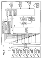
- FIG. 4 is a block diagram that illustrates the configuration of the receiving apparatus illustrated in FIG. 1 .
- the first receiving antenna 41 (the element 41a, the active circuit 41b) is representatively described.
- the receiving apparatus 5 includes the antenna cable 51 connected to each of the first to eighth receiving antennas 41 to 48 via the connector 49 of the receiving apparatus 5, a cable connector 52 to which the antenna cable 51 is connected, an antenna changeover selection switch unit 53 that selectively switches among the first to eighth receiving antennas 41 to 48, a receiving circuit 54 that performs processing such as modulation on a radio signal received through any one of the first to eighth receiving antennas 41 to 48 which is selected by the antenna changeover selection switch unit 53, a signal processing circuit 55 that performs signal processing of extracting image data and the like from the radio signal output from the receiving circuit 54, a received-field-strength detector 56 that detects a received field strength based on the strength of the radio signal output from the receiving circuit 54, an antenna power supply changeover selector 57 that switches among the first to eighth receiving antennas 41 to 48 and supplies power to any one of the first to eighth receiving antennas 41 to 48, a display unit 58 that displays an image corresponding to the image data received from the capsule endoscope 3,
- the antenna cable 51 is configured by a coaxial cable.
- the antenna cable 51 has core wires, the number of which corresponds to the number of the first to eighth receiving antennas 41 to 48.
- the antenna cable 51 has eight core wires.
- the antenna cable 51 transmits the radio signals received by each of the first to eighth receiving antennas 41 to 48 to the receiving apparatus 5, and transmits the power supplied from the receiving apparatus 5 to each of the first to eighth receiving antennas 41 to 48.
- the antenna cable 51 is connected to the cable connector 52 in a detachable manner.
- the cable connector 52 is electrically connected to the antenna changeover selection switch unit 53 and the antenna power supply changeover selector 57.
- the antenna changeover selection switch unit 53 is configured by a mechanical switch, a semiconductor switch, or the like.
- the antenna changeover selection switch unit 53 is electrically connected to each of the first to eighth receiving antennas 41 to 48 via a capacitor C1.
- a switch signal S1 used to switch the receiving antenna which receives the radio signal is input from the control unit 62, the antenna changeover selection switch unit 53, for example, selects the first receiving antenna 41 as instructed by the switch signal S1 and outputs the received radio signal through the selected first receiving antenna 41 to the receiving circuit 54.
- the capacitance of each of capacitors respectively connected to the first to eighth receiving antennas 41 to 48 is equal to the capacitance of the capacitor C1.
- the receiving circuit 54 performs predetermined processing such as demodulation or amplification on the radio signal received through the first receiving antenna 41 selected by the antenna changeover selection switch unit 53, and outputs the processed signal to each of the signal processing circuit 55 and the received-field-strength detector 56.
- the signal processing circuit 55 extracts the image data from the radio signal input from the receiving circuit 54, performs predetermined processing, for example, various kinds of image processing and/or A/D conversion processing on the extracted image data, and outputs the resultant signal to the control unit 62.
- the received-field-strength detector 56 detects the received field strength corresponding to the strength of the radio signal input from the receiving circuit 54, and outputs a received-field-strength signal (RSSI: Received Signal Strength Indicator) corresponding to the detected received field strength to the control unit 62.
- RSSI Received Signal Strength Indicator
- the antenna power supply changeover selector 57 is electrically connected to each of the first to eighth receiving antennas 41 to 48 via a coil L1.
- the antenna power supply changeover selector 57 supplies the power to the first receiving antenna 41 selected by the antenna changeover selection switch unit 53 through the antenna cable 51.
- the antenna power supply changeover selector 57 includes a power supply changeover selection switch unit 571 and an abnormality detector 572.
- the electrical characteristic of each of coils respectively connected to the first to eighth receiving antennas 41 to 48 is equal to the characteristic of the coil L1.
- the power supply changeover selection switch unit 571 is configured by a mechanical switch, a semiconductor switch, or the like. When a selection signal S2 used to select the receiving antenna which is to be supplied with power is input from the control unit 62, the power supply changeover selection switch unit 571 selects, for example, the first receiving antenna 41 as instructed by the selection signal S2, and supplies power only to the selected first receiving antenna 41.
- the abnormality detector 572 outputs, to the control unit 62, an abnormality signal indicating an event that abnormality is caused in the first receiving antenna 41 to which power is supplied, when abnormality occurs in the first receiving antenna 41 to which power is supplied. Specifically, the abnormality detector 572 detects a disconnection abnormality or a short-circuit abnormality in the first receiving antenna 41 based on the voltage supplied to the first receiving antenna 41 selected by the power supply changeover selection switch unit 571, and outputs the detection result to the control unit 62.
- the display unit 58 is configured by using a display panel composed of liquid crystal, organic Electro Luminescence (EL), or the like.
- the display unit 58 displays various information such as images corresponding to the image data captured by the capsule endoscope 3, operation status of the receiving apparatus 5, patient information of the subject 2, and examination data and time.
- the storage unit 59 is configured by a semiconductor memory such as flash memory and Random Access Memory (RAM) provided fixedly in the receiving apparatus 5.
- the storage unit 59 stores the image data captured by the capsule endoscope 3 and/or various kinds of information associated with the image data, for example, position information of the capsule endoscope 3, orientation information of the capsule endoscope 3, received-field-strength information, and identification information used to identify the receiving antenna that has received the radio signal.
- the storage unit 59 stores various kinds of programs to be executed by the receiving apparatus 5.
- the storage unit 59 may have a function as a recording medium interface which stores information in an external recording medium such as a memory card, and reads information stored in the recording medium.
- the I/F unit 60 functions as a communication interface and mutually transmits and receives data to and from the image display apparatus 6 through the cradle 6a.
- the power supply unit 61 is configured by a battery detachable from the receiving apparatus 5 and a switch unit which performs switching between ON state and OFF state.
- the power supply unit 61 supplies necessary driving power to each unit of the receiving apparatus 5 when it is in ON state, and stops supplying the driving power to each unit of the receiving apparatus 5 when it is in OFF state.
- the control unit 62 is configured by a Central Processing Unit (CPU) or the like.
- the control unit 62 reads the programs out of the storage unit 59 and executes the programs, and collectively controls the operation of the receiving apparatus 5 by giving instructions or transmitting data to the respective units which constitute the receiving apparatus 5.
- the control unit 62 includes a selection controller 621 and an abnormality information adding unit 622.
- the selection controller 621 performs control of selecting the receiving antenna to receive the radio signal transmitted from the capsule endoscope 3 and supplying power only to the selected receiving antenna. Specifically, the selection controller 621 performs control of selecting the receiving antenna to receive the radio signal transmitted from the capsule endoscope 3 and supplying power only to the selected receiving antenna, based on the received electric field strengths of the first to eighth receiving antennas 41 to 48 which are detected by the received-field-strength detector 56.
- the selection controller 621 drives the antenna changeover selection switch unit 53 at every predetermined timing, for example, every 100 msec to sequentially select the receiving antennas to receive the radio signal transmitted from any one of the first to eighth receiving antennas 41 to 48, and repeats such a process until the received electric field strength detected by the received-field-strength detector 56 reaches a predetermined value.
- the abnormality information adding unit 622 adds abnormality information indicating that abnormality is caused in any one of the first to eighth receiving antennas 41 to 48 to the radio signals which are respectively received by the first to eighth receiving antennas 41 to 48, and outputs the resultant signal to the storage unit 59. Specifically, the abnormality information adding unit 622 adds a flag indicating the abnormality information to the image data which has been subjected to the signal processing performed by the signal processing circuit 55, for each of the radio signals respectively received by the first to eighth receiving antennas 41 to 48, and outputs the resultant signal to the storage unit 59.
- the selection controller 621 performs control of selecting any one of the first to eighth receiving antennas 41 to 48 by activating the antenna changeover selection switch unit 53 at every predetermined timing, for example, every 100 msec and supplying power only to the receiving antenna selected by the antenna changeover selection switch unit 53.
- the abnormality detector 572 detects each of the disconnection abnormality and the short-circuit abnormality in each of the first to eighth receiving antennas 41 to 48 sequentially selected by the selection controller 621, and outputs the detection result to the control unit 62.
- the control unit 62 determines whether abnormality is caused in any one of the first to eighth receiving antennas 41 to 48 based on the detection result of the abnormality detector 572.
- the control unit 62 may output the detection result with respect to the first to eighth receiving antennas 41 to 48 to the display unit 58. In this way, the user can check whether there is abnormality caused in any one of the first to eighth receiving antennas 41 to 48. As a result, it is possible to prevent the examination result of the subject 2 from becoming useless, which may occur because it is difficult to acquire highly precise and accurate image data due to the abnormality of the receiving antenna.
- the capsule endoscope 3 After pre-processing performed along with the activation of the receiving apparatus 5, the capsule endoscope 3 is introduced into the subject 2.
- the selection controller 621 performs control of sequentially switching and selecting the receiving antenna to receive the radio signal transmitted from the capsule endoscope 3 at every predetermined timing and supplying power only to the selected receiving antenna.
- the selection controller 621 selects the receiving antenna where the received electric field strength detected by the received-field-strength detector 56 is strongest among the first to eighth receiving antennas 41 to 48, and supplies power only to the selected receiving antenna.
- the selection controller 621 performs control of switching among the first to eighth receiving antennas 41 to 48 to select one receiving antenna to receive the radio signal transmitted from the capsule endoscope 3 at every predetermined timing until the capsule endoscope 3 is excreted from the inside of the subject 2, and supplying power only to the selected receiving antenna.
- the abnormality detector 572 detects each of the disconnection abnormality and the short-circuit abnormality caused in one of the first to eighth receiving antennas 41 to 48 selected by the selection controller 621, and outputs the detection result to the control unit 62.
- the control unit 62 determines whether abnormality is caused in any of the first to eighth receiving antennas 41 to 48 based on the detection result of the abnormality detector 572.
- the abnormality information adding unit 622 adds abnormality information indicating that abnormality is caused in any of the first to eighth receiving antennas 41 to 48 to the image data, which has been received by any one of the first to eighth receiving antennas 41 to 48 and has been subjected to the signal processing performed by the signal processing circuit 55, and stores the resultant in the storage unit 59.
- the image display apparatus 6 displays the abnormal information added to the image data. Accordingly, it is possible to determine whether abnormality was caused in the first to eighth receiving antennas 41 to 48 at certain time points, which enables to determine whether the image data can be used for inspection.
- the antenna apparatus includes the first receiving antenna 41 and the second receiving antenna 42 disposed at positions on a plane, which face each other with the reference point O 1 therebetween and are in an equal distance from the reference point O 1 , the third receiving antenna 43 and the fourth receiving antenna 44 disposed at positions which are in-plane rotated about the reference point O 1 by 90 degrees from the first receiving antenna 41 and the second receiving antenna 42, respectively, the fifth receiving antenna 45 and the sixth receiving antenna 46 disposed at positions which are closer to outer peripheries of the plane than the first receiving antenna 41 and the second receiving antenna 42 and which are in-plane rotated about the reference point O 1 by 45 degrees from the first receiving antenna 41 and the second receiving antenna 42, respectively, and the seventh receiving antenna 47 and the eighth receiving antenna 48 disposed at positions which are in-plane rotated about the reference point O 1 by 90 degrees from the fifth receiving antenna 45 and the sixth receiving antenna 46, respectively.
- the radio signal transmitted from the capsule endoscope 3 introduced in the subject 2 is precisely detected and the position
- the selection controller 621 performs control of selecting one receiving antenna to receive the radio signal transmitted from the outside from among the first to eighth receiving antennas 41 to 48 and supplying power only to the selected receiving antenna.
- the selection controller 621 performs control of selecting one receiving antenna to receive the radio signal transmitted from the outside from among the first to eighth receiving antennas 41 to 48 and supplying power only to the selected receiving antenna.
- the abnormality detector 572 detects each of the disconnection abnormality and the short-circuit abnormality and outputs the detection result to the control unit 62.
- the control unit 62 can easily determine whether there is abnormality caused in any one of the first to eighth receiving antennas 41 to 48 at the time of activation of the capsule endoscope 3 and the receiving apparatus 5, or during the examination of the subject 2.
- the antenna cable which connects the antenna apparatus 4 and the receiving apparatus 5 can be integrated in one cable, resulting in a reduction in the failure of the antenna cable.
- the radio signal transmitted from the capsule endoscope 3 can be received without having to closely attach the first to eighth receiving antennas 41 to 48 to the subject 2.
- the received field strength is measured by all the first to eighth receiving antennas 41 to 48, and the position and direction of the capsule endoscope 3 are detected while taking balance among the received field strengths of the first to eighth receiving antennas 41 to 48.
- the position of the capsule endoscope 3 in the subject 2 can be easily estimated.
- the capsule endoscope 3 modulates the image data acquired from the subject 2 and transmits the result as the radio signal.
- the image data can be reliably restored.
- the third receiving antenna 43 and the fourth receiving antenna 44 are disposed at positions which are in-plane rotated about the reference point O 1 by 90 degrees from the first receiving antenna 41 and the second receiving antenna 42, respectively
- the fifth receiving antenna 45 and the sixth receiving antenna 46 are disposed at positions which are in-plane rotated about the reference point O 1 by 45 degrees from the first receiving antenna 41 and the second receiving antenna 42, respectively
- the seventh receiving antenna 47 and the eighth receiving antenna 48 are disposed at positions which are in-plane rotated about the reference point O 1 by 90 degrees from the fifth receiving antenna 45 and the sixth receiving antenna 46, respectively.
- the positions to arrange the fifth to eighth receiving antennas 45 to 48 may be changed.
- the third receiving antenna 43 and the fourth receiving antenna 44 may be disposed at such positions on the plate unit 40 that the gravity center of the third receiving antenna 43 and the gravity center of the fourth receiving antenna 44 are in an equal distance from the reference point O 1 and a straight line which connects the gravity center of the third receiving antenna 43 and the gravity center of the fourth receiving antenna 44 is at an angle of 90 degrees with respect to a straight line which connects the gravity center of the first receiving antenna 41 and the gravity center of the second receiving antenna 42.
- the fifth receiving antenna 45 and the eighth receiving antenna 48 may be disposed at such positions on the plate unit 40 that the gravity center of the fifth receiving antenna 45 and the gravity center of the eighth receiving antenna 48 are arranged in straight lines, respectively, which are different from each other and each of which is at an angle of 45 degrees with respect to both a straight line which connects the gravity center of the first receiving antenna 41 and the gravity center of the second receiving antenna 42 and a straight line which connects the gravity center of the third receiving antenna 43 and the gravity center of the fourth receiving antenna 44.
- FIG. 5 is a plan view that illustrates a schematic configuration of an antenna apparatus according to Modification 1 of the embodiment of the present invention. As illustrated in FIG. 5 , in an antenna apparatus 70, first to eighth receiving antennas 41 to 48 are disposed at positions which are rotated about the reference point O 1 by 45 degrees respectively from the arrangement positions in the above described embodiment. With this configuration, the same effects as the above-described embodiment can be achieved.
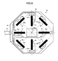
- FIG. 6 is a plan view that illustrates a schematic configuration of an antenna apparatus according to Modification 2 of the embodiment of the present invention.
- an element 41a of a first receiving antenna 41 and an element 42a of a second receiving antenna 42 are arranged to face each other with a reference point O 1 therebetween on a straight line passing the reference point O 1 .
- an element 43a of a third receiving antenna 43 and an element 44a of a fourth receiving antenna 44 are arranged to face each other with the reference point O 1 therebetween on a straight line passing the reference point O 1 .
- FIG. 7 is a plan view that illustrates a schematic configuration of an antenna apparatus according to Modification 3 of the embodiment of the present invention.
- an element 45a of a fifth receiving antenna 45 and an element 46a of a sixth receiving antenna 46 are arranged to face each other with a reference point O 1 therebetween in a straight line passing the reference point O 1 .
- an element 47a of a seventh receiving antenna 47 and an element 48a of an eighth receiving antenna 48 are arranged to face each other with a reference point O 1 therebetween in a straight line passing the reference point O 1 .
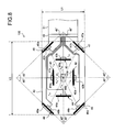
- FIG. 8 is a plan view that illustrates a schematic configuration of an antenna apparatus according to Modification 4 of the embodiment of the present invention.
- an antenna apparatus 100 includes: a first receiving antenna 41 and a second receiving antenna 42 disposed at positions on a plane, which face each other with a reference point O 1 therebetween and are in a distance of r11 from the reference point O 1 ; a third receiving antenna 43 and a fourth receiving antenna 44 disposed at positions which are in-plane rotated about the reference point O 1 by 90 degrees from a straight line which connects the gravity center of the first receiving antenna 41 and the gravity center of the second receiving antenna 42; a fifth receiving antenna 45 and a sixth receiving antenna 46 disposed at positions which are closer to outer peripheries of the plane than the first receiving antenna 41 and the second receiving antenna 42, an extending direction of each of the fifth and sixth receiving antennas 45 and 46 being a straight line having an angle of 45 degrees with respect to a straight line which connects the gravity center of the first receiving antenna 41 and the gravity center of the second receiving antenna 42, the gravity centers of the fifth and sixth receiving antennas 45 and 46 being disposed at positions within the plane; and a
- the third receiving antenna 43 and the fourth receiving antenna 44 are disposed respectively at positions on a plate unit 40 which are in an equal distance of r 12 (r 11 ⁇ r 12 ) from the reference point O 1 , and are more away from each other than those of the first receiving antenna 41 and the second receiving antenna 42.
- the fifth to eighth receiving antennas 45 to 48 are disposed respectively at positions on the plate unit 40 which are in an equal distance of r 13 (r 12 ⁇ r 13 ) from the reference point, and are more away from each other than those of the third receiving antenna 43 and the fourth receiving antenna 44.
- the plate unit 40 of the receiving antenna apparatus 100 may be decreased in length L1 and increased in width L2.
- both of the third receiving antenna 43 and the fourth receiving antenna 44 may be arranged on the outer periphery of the plate unit 40.
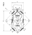
- FIG. 9 is a plan view that illustrates a schematic configuration of an antenna apparatus according to Modification 5 of the embodiment of the present invention.
- the first receiving antenna 41 and the second receiving antenna 42 are described as the third receiving antenna 43 and the fourth receiving antenna 44
- the third receiving antenna 43 and the fourth receiving antenna 44 are described as the first receiving antenna 41 and the second receiving antenna 42.
- a first receiving antenna 41 and a second receiving antenna 42 are disposed respectively at positions on a plate unit 40 which are in an equal distance of r 21 (r 12 ⁇ r 21 ) from a reference point O 1 , are more away from each other than those of a third receiving antenna 43 and a fourth receiving antenna 44, and are closer to outer peripheries of the plate unit 40.
- the first receiving antenna 41 and the second receiving antenna 42 are disposed such that an element 40a and an element 41a thereof are both formed on the outer periphery of the plate unit 40.
- the fifth to eighth receiving antennas 45 to 48 are disposed respectively at positions on the plate unit 40 which are in an equal distance of r 13 (r 12 ⁇ r 13 ) from the reference point O 1 , and are more away from each other than those of the third receiving antenna 43 and the fourth receiving antenna 44.
- the receiving antenna 110 can be configured such that the length L3 of the plate unit 40 is further reduced compared with the length L1 of Modification 4 of the embodiment described above (L1 > L3) and the width L4 of the plate unit 40 is increased.
- the plate unit 40 thereof may have a length L3 of 140 mm and a width L4 of 190 mm.
- the first receiving antenna 41 and the second receiving antenna 42 may be disposed on the outer peripheries of the plate unit 40, respectively.
- transformation circuits which transform balanced state to unbalanced state may be connected to the first to eighth receiving antennas 41 to 48, respectively.
- first to eighth receiving antennas 41 to 48 are configured by dipole antennas in the embodiment described above, the first to eighth receiving antennas 41 to 48 may be configured by loop antennas or open type antennas.
- the abnormality detector 572 detects the abnormality of the first to eighth receiving antennas 41 to 48 based on voltage in the embodiment described above, the abnormality of the first to eighth receiving antennas 41 to 48 may be detected based on current and/or power. Yet furthermore, the abnormality detector 572 may detect the abnormality of the first to eighth receiving antennas 41 to 48 based on a combination of voltage, current, and power.
- the image display apparatus 6 can acquire in-vivo image data captured by the capsule endoscope 3 in various ways.
- a memory card such as a USB memory and a compact flash (registered trademark) which can be removed from the receiving apparatus 5 may be used instead of the built-in storage unit 59.
- the image display apparatus 6 may be provided with a communication function, so that the image data may be acquired from the receiving apparatus 5 by wired communication or wireless communication.
Landscapes
- Life Sciences & Earth Sciences (AREA)
- Health & Medical Sciences (AREA)
- Surgery (AREA)
- Engineering & Computer Science (AREA)
- Animal Behavior & Ethology (AREA)
- Public Health (AREA)
- Biomedical Technology (AREA)
- Heart & Thoracic Surgery (AREA)
- Medical Informatics (AREA)
- Molecular Biology (AREA)
- Physics & Mathematics (AREA)
- Biophysics (AREA)
- Pathology (AREA)
- Veterinary Medicine (AREA)
- General Health & Medical Sciences (AREA)
- Computer Networks & Wireless Communication (AREA)
- Nuclear Medicine, Radiotherapy & Molecular Imaging (AREA)
- Optics & Photonics (AREA)
- Radiology & Medical Imaging (AREA)
- Endoscopes (AREA)
- Variable-Direction Aerials And Aerial Arrays (AREA)
Abstract
Description
- The present invention relates to a receiving antenna apparatus that receives a radio signal transmitted from a capsule endoscope inside of a subject.
- Conventionally, in the field of an endoscope, a capsule endoscope with a built-in imaging function and a radio communication function, which are provided in a capsule-shaped casing formed to a size that can be introduced into the gut of a subject such as a patient, is known. The capsule endoscope is first swallowed from the mouth of the subject and then it moves in the inside of the subject such as the gut by peristaltic movement and the like. Then, it sequentially captures images of the inside of the subject to generate image data, and sequentially transmits the image data.
- The image data thus transmitted from the capsule endoscope by wireless transmission is received by a receiving apparatus through a receiving antenna provided outside the subject. The receiving apparatus stores the image data received through the receiving antenna in a built-in memory.
- The subject can freely act during a period until the capsule endoscope is excreted after the capsule endoscope is swallowed, by carrying the receiving apparatus that has a radio communication function and a memory function. After the examination, a practitioner such as a doctor puts the image data accumulated in the memory of the receiving apparatus in an image display apparatus so that images of the inside of the subject which correspond to the images obtained by the capsule endoscope, that is, the internal organs' images are displayed on a display of the image display apparatus. The practitioner observes the images of the internal organs and the like displayed on the display, and diagnoses the subject.
- In receiving the radio signal transmitted from the capsule endoscope, a typical receiving apparatus has a plurality of receiving antennas arranged in a dispersed manner outside the subject, selects one antenna with the strongest received strength, and receives the radio signal by the selected antenna. For example, there is a known receiving apparatus in which reception switching among a plurality of antennas placed outside a subject is performed and which detects the position of a capsule endoscope in the subject that is the source of a radio signal based on the field strength received by each antenna (See Patent Literature 1).
-
- Japanese Patent Application Laid-open Publication No.
2003-000608 - In the antenna apparatus of the capsule endoscope described above, however, positions to arrange respective receiving antennas that receive the radio signal transmitted from the capsule endoscope introduced in the inside of the subject are not disclosed. Therefore, there is a case where the radio signal transmitted from the capsule endoscope cannot be received precisely, depending on the positions to arrange the receiving antennas.
- The present invention has been achieved in view of the foregoing and an object of the present invention is to provide an antenna apparatus that can receive a radio signal transmitted from a capsule endoscope introduced in an inside of a subject precisely.
- To solve the problem described above and to achieve the object, an antenna apparatus according to the present invention, an antenna apparatus according to the present invention includes: a first receiving antenna and a second receiving antenna respectively disposed at positions on a plane which are in an equal distance from a reference point and face each other with the reference point therebetween; a third receiving antenna and a fourth receiving antenna disposed at positions on the plane, a gravity center of the third receiving antenna and a gravity center of the fourth receiving antenna being in an equal distance from the reference point on the plane, a straight line connecting the gravity centers of the third receiving antenna and the fourth receiving antenna being at an angle of 90 degrees with respect to a straight line connecting a gravity center of the first receiving antenna and a gravity center of the second receiving antenna; and a fifth receiving antenna, a sixth receiving antenna, a seventh receiving antenna, and an eighth receiving antenna disposed respectively at positions on the plane, gravity centers of the fifth to eighth receiving antennas being on straight lines different from each other, which are rotated by an angle of 45 degrees from the straight line connecting the gravity centers of the first receiving antenna and the second receiving antenna and the straight line connecting the gravity centers of the third receiving antenna and the gravity center of the fourth receiving antenna, respectively.
- In the antenna apparatus according to the above invention, the first to fourth receiving antennas are disposed respectively at positions which are in an equal distance from the reference point within the plane.
- In the antenna apparatus according to the above invention, the third and fourth receiving antennas are in an equal distance from the reference point and are disposed, with respect to the reference point, closer to outer peripheries of the plane than the first and second receiving antennas.
- In the antenna apparatus according to the above invention, the first to eighth receiving antennas are balanced antennas exhibiting a larger loss in cross polarization than in main polarization.
- In the antenna apparatus according to the above invention, the first to eighth receiving antennas are dipole antennas each of which has two linear elements, the two linear elements being arranged in a straight line.
- In the antenna apparatus according to the above invention, the first to eighth receiving antennas are provided with first to eighth active circuits, respectively.
- In the antenna apparatus according to the above invention, the first to eighth receiving antennas are disposed on one plate unit.
- In the antenna apparatus according to the above invention, the third and fourth receiving antennas are disposed on outer peripheries of the plate unit.
- The antenna apparatus according to the above invention further includes first to eighth transmission lines to transmit and receive a signal to and from the first to eighth receiving antennas, respectively, and wherein the first to eighth transmission lines gather at an end portion of the plate unit.
- In the antenna apparatus according to the above invention, the plate unit includes a positioning unit that positions the antenna apparatus with respect to a target object to which the antenna apparatus is mounted.
- An antenna apparatus according to the present invention includes: first and second receiving antennas respectively disposed at positions on a plane which are in an equal distance from a reference point and face each other with the reference point therebetween; third and fourth receiving antennas disposed at positions on the plane, a gravity center of the third receiving antenna and a gravity center of the fourth receiving antenna being in an equal distance from the reference point on the plane, a straight line connecting the gravity centers of the third and fourth receiving antennas being at an angle of 90 degrees with respect to a straight line connecting gravity centers of the first and second receiving antennas; and a fifth receiving antenna, a sixth receiving antenna, a seventh receiving antenna, and an eighth receiving antenna disposed respectively at positions on the plane, gravity centers of the fifth to eighth receiving antennas being on straight lines different from each other, which are rotated by an angle of 45 degrees from the straight line connecting the gravity centers of the first and second receiving antennas and the straight line connecting the gravity centers of the third and fourth receiving antennas, respectively. As a result, there is an advantage in the present invention in that a radio signal transmitted from the capsule endoscope introduced in an inside of a subject can be received precisely.
-
-
FIG. 1 is a schematic diagram that illustrates an outline of a configuration of a capsule endoscope system provided with an antenna apparatus according to an embodiment of the present invention; -
FIG. 2 is a plan view that illustrates a schematic configuration of the antenna apparatus according to the embodiment of the present invention; -
FIG. 3 is a block diagram that illustrates a schematic configuration of a first receiving antenna illustrated inFIG. 2 ; -
FIG. 4 is a block diagram that illustrates a schematic configuration of a receiving apparatus illustrated inFIG. 1 ; -
FIG. 5 is a plan view that illustrates a schematic configuration of an antenna apparatus according toModification 1 of the embodiment of the present invention; -
FIG. 6 is a plan view that illustrates a schematic configuration of an antenna apparatus according toModification 2 of the embodiment of the present invention; -
FIG. 7 is a plan view that illustrates a schematic configuration of an antenna apparatus according toModification 3 of the embodiment of the present invention; -
FIG. 8 is a plan view that illustrates a schematic configuration of an antenna apparatus according toModification 4 of the embodiment of the present invention; and -
FIG. 9 is a plan view that illustrates a schematic configuration of an antenna apparatus according to Modification 5 of the embodiment of the present invention. - Hereinbelow, an antenna apparatus according to an embodiment of the present invention is described referring to the drawings. In the following description, a capsule endoscope system including a capsule endoscope, which is introduced into the inside of a subject to capture in-vivo images of the subject, is presented as an example of an antenna apparatus according the present invention. However, the present invention is not limited by this embodiment.
- As illustrated in
FIG. 1 , acapsule endoscope system 1 includes acapsule endoscope 3 that captures an in-vivo image of asubject 2, anantenna apparatus 4 that receives a radio signal transmitted from thecapsule endoscope 3 introduced in thesubject 2, a receiving apparatus 5 that performs predetermined processing on the radio signal input from theantenna apparatus 4 and stores the processing result, and an image display apparatus 6 that displays an image corresponding to image data of the inside of thesubject 2 captured by thecapsule endoscope 3. - The
capsule endoscope 3 has an imaging function to capture an image of the inside of thesubject 2, and a radio communication function to transmit image data obtained by capturing an image of the inside of thesubject 2 to the receiving apparatus 5. Thecapsule endoscope 3 is swallowed by thesubject 2 so that it passes through the esophagus of thesubject 2 and moves in the body cavity of the subject by peristaltic movement of the lumen of the gut. Thecapsule endoscope 3 sequentially captures images of the body cavity of thesubject 2 at intervals of a minute time, for example, an interval of 0.5 seconds while moving in the body cavity, and sequentially generates and transmits image data of the captured images of the inside of thesubject 2 to the receiving apparatus 5. In this case, thecapsule endoscope 3 generates a transmission signal, which includes the image data and received-field-strength detection data including position information (beacon) etc. which makes received field strength easy to be detected, and transmits a radio signal obtained by modulating the generated transmission signal to the receiving apparatus 5 by wireless transmission. - The
antenna apparatus 4 outputs the radio signal, received from thecapsule endoscope 3, to the receiving apparatus 5 through anantenna cable 51. Theantenna apparatus 4 is fixed to thesubject 2 with a belt or the like during the examination. - The receiving apparatus 5 acquires the radio signal, which is transmitted from the
capsule endoscope 3 by wireless transmission, through theantenna apparatus 4 and theantenna cable 51. The receiving apparatus 5 acquires the image data of the inside of thesubject 2 based on the radio signal received from thecapsule endoscope 3. The receiving apparatus 5 stores received-field-strength information and time information which indicates a time point in association with the received image data. The receiving apparatus 5 is carried by thesubject 2 while thecapsule endoscope 3 is capturing images, that is, during a period from when the endoscope is introduced from the mount of thesubject 2 and to when the endoscope passes through the gut and is finally excreted out of thesubject 2. After the examination using thecapsule endoscope 3 ends, the receiving apparatus 5 is removed from thesubject 2 and is then connected to the image display apparatus 6 so that information on the image, data etc. received from thecapsule endoscope 3 can be transmitted. - The image display apparatus 6 is configured by a work station or a personal computer including a display such as a liquid crystal display. The image display apparatus 6 displays an image corresponding to the image data in the
subject 2 acquired by the receiving apparatus 5. Acradle 6a that reads the image data from the memory of the receiving apparatus 5 and anoperation input devices 6b such as a keyboard and a mouse are connected to the image display apparatus 6. Thecradle 6a acquires image data, the received-field-strength information associated with the image data, time information, and relevant information such as identification information of thecapsule endoscope 3, from the memory of the receiving apparatus 5 when the receiving apparatus 5 is mounted, and transmits the acquired various information to the image display apparatus 6. Theoperation input device 6b accepts the input from the user. As a result, the user observes living body parts in thesubject 2, for example, the esophagus, the stomach, the small intestine, and the large intestine, and makes a diagnosis on thesubject 2 while operating theoperation input device 6b and viewing the images of the inside of thesubject 2 which are sequentially displayed by the image display apparatus 6. - Next, details of a configuration of the
antenna apparatus 4 illustrated inFIG. 2 are described.FIG. 2 is a plan view that illustrates a schematic configuration of theantenna apparatus 4. As illustrated inFIG. 2 , theantenna apparatus 4 includes aplate unit 40, afirst receiving antenna 41, asecond receiving antenna 42, athird receiving antenna 43, afourth receiving antenna 44, a fifth receivingantenna 45, a sixth receivingantenna 46, a seventh receivingantenna 47, aneighth receiving antenna 48, and aconnector 49. The first toeighth receiving antennas 41 to 48 are provided on oneplate unit 40. - The
plate unit 40 is formed of a sheet-like flexible substrate. The principal surface of theplate unit 40 is substantially octagonal. Theplate unit 40 is formed to a size that can cover the entire surface of the abdomen of the subject 2, for example, 200 mm in length x 200 mm in width. Theplate unit 40 has anopening 40a.
Theopening 40a is formed such that the center is coincident with a reference point O1 of theplate unit 40. Theopening 40a functions as a positioning unit which positions the antenna apparatus with respect to the subject 2 when the antenna apparatus is attached to thesubject 2. As a result, when theplate unit 40 is attached to thesubject 2, theantenna apparatus 4 can be easily positioned. Theopening 40a may be formed using a transparent member, for example, a transparent vinyl sheet, etc. Incidentally, the principal surface of theplate unit 40 does not necessarily have a substantial octagonal shape, but may have a rectangular shape, etc. - The
first receiving antenna 41 and thesecond receiving antenna 42 are disposed at positions which face each another with the reference point O1 therebetween. Thefirst receiving antenna 41 and thesecond receiving antenna 42 are disposed at positions which are in an equal distance from the reference point O1. Specifically, the first receivingantenna 41 and thesecond receiving antenna 42 are disposed respectively at the positions on theplate unit 40 which are in a distance of r1 from the reference point O1. As for the first receivingantenna 41 and thesecond receiving antenna 42, anelement 41a and anelement 42a thereof are formed on theplate unit 40 as printed circuits. Thefirst receiving antenna 41 and thesecond receiving antenna 42 include anactive circuit 41b and anactive circuit 42b connected to theelement 41a and theelement 42a, respectively. Theactive circuits plate unit 40 as planar circuits, respectively. Theactive circuits antenna 41 and thesecond receiving antenna 42, performs amplification processing including amplification and attenuation on a received radio signal, and performs balanced-to-unbalanced transformation on the received radio signal. Thefirst receiving antenna 41 and thesecond receiving antenna 42 are connected to theconnector 49 provided in theplate unit 40 via planar transmission lines (striplines), respectively. - The
third receiving antenna 43 and the fourth receivingantenna 44 are disposed at positions which are in-plane rotated about the reference point O1 by 90 degrees respectively from the first receivingantenna 41 and thesecond receiving antenna 42. Thethird receiving antenna 43 and the fourth receivingantenna 44 are disposed respectively at positions on theplate unit 40 which are in a distance of r1 from the reference point O1. As for the third receivingantenna 43 and the fourth receivingantenna 44, anelement 43a and anelement 44a thereof are both formed on theplate unit 40 as printed circuits. Thethird receiving antenna 43 and the fourth receivingantenna 44 include anactive circuit 43b and anactive circuit 44b connected to theelement 43a and theelement 44a, respectively. Thethird receiving antenna 43 and the fourth receivingantenna 44 are connected to theconnector 49 via planar transmission lines, respectively. - The
fifth receiving antenna 45 and the sixth receivingantenna 46 are disposed at positions which are in-plane rotated about the reference point O1 by 45 degrees respectively from the first receivingantenna 41 and thesecond receiving antenna 42. Thefifth receiving antenna 45 and the sixth receivingantenna 46 are disposed to be closer to outer peripheries of the plane than the first receivingantenna 41 and thesecond receiving antenna 42 within the plane. Specifically, the fifth receivingantenna 45 and the sixth receivingantenna 46 are disposed respectively at positions on theplate unit 40 which are each in a distance of r2 (r1 < r2) from the reference point O1. As for the fifth receivingantenna 45 and the sixth receivingantenna 46, anelement 45a and anelement 46a thereof are both formed on theplate unit 40 as printed circuits. Thefifth receiving antenna 45 and the sixth receivingantenna 46 include anactive circuit 45b and anactive circuit 46b connected to theelement 45a and theelement 46a, respectively. Thefifth receiving antenna 45 and the sixth receivingantenna 46 are connected to theconnector 49 via planar transmission lines, respectively. - The
seventh receiving antenna 47 and the eighth receivingantenna 48 are disposed at positions which are in-plane rotated about the reference point O1 by 90 degrees respectively from the fifth receivingantenna 45 and the sixth receivingantenna 46. Theseventh receiving antenna 47 and the eighth receivingantenna 48 are disposed to be closer to outer peripheries of the plane than the first receivingantenna 41 and thesecond receiving antenna 42 within the plane. Specifically, the seventh receivingantenna 47 and the eighth receivingantenna 48 are disposed respectively at positions on theplate unit 40 which are each in a distance of r2 (r1 < r2) from the reference point O1. As for the seventh receivingantenna 47 and the eighth receivingantenna 48, anelement 47a and anelement 48a thereof are both formed on theplate unit 40 as printed circuits. Theseventh receiving antenna 47 and the eighth receivingantenna 48 include anactive circuit 47b and anactive circuit 48b connected to theelement 47a and theelement 48a, respectively. Theseventh receiving antenna 47 and the eighth receivingantenna 48 are connected to theconnector 49 via planar transmission lines, respectively. - Here, details of the configuration of the first receiving
antenna 41 illustrated inFIG. 2 are described.FIG. 3 is a block diagram that illustrates the configuration of the first receiving antenna. - As illustrated in
FIG. 3 , the first receivingantenna 41 is configured by a balanced antenna. Specifically, the first receivingantenna 41 is configured such that theelement 41a is a dipole antenna having two linear conductive wires. In the first receivingantenna 41, the two linear conductive wires of theelement 41a are in a straight line, symmetrically extend to left and right sides, and have the same length. Because of this configuration, the first receivingantenna 41 exhibits large loss in cross polarization compared with main polarization. Since the second toeighth receiving antennas 42 to 48 which are described above have the same configuration as the first receivingantenna 41, the description thereof is not repeated. In the present embodiment, the number of receiving antennas is not necessarily construed to be limited to 8, but may be more than 8. - With the configuration described above, the
antenna apparatus 4 can receive all polarizations transmitted by thecapsule endoscope 3 regardless of the orientation and position of thecapsule endoscope 3 in thesubject 2. - Next, details of the configuration of the receiving apparatus illustrated in
FIG. 1 are described.FIG. 4 is a block diagram that illustrates the configuration of the receiving apparatus illustrated inFIG. 1 . In the following description, when any one of the first toeighth receiving antennas 41 to 48 is described, the first receiving antenna 41 (theelement 41a, theactive circuit 41b) is representatively described. - As illustrated in
FIG. 4 , the receiving apparatus 5 includes the antenna cable 51 connected to each of the first to eighth receiving antennas 41 to 48 via the connector 49 of the receiving apparatus 5, a cable connector 52 to which the antenna cable 51 is connected, an antenna changeover selection switch unit 53 that selectively switches among the first to eighth receiving antennas 41 to 48, a receiving circuit 54 that performs processing such as modulation on a radio signal received through any one of the first to eighth receiving antennas 41 to 48 which is selected by the antenna changeover selection switch unit 53, a signal processing circuit 55 that performs signal processing of extracting image data and the like from the radio signal output from the receiving circuit 54, a received-field-strength detector 56 that detects a received field strength based on the strength of the radio signal output from the receiving circuit 54, an antenna power supply changeover selector 57 that switches among the first to eighth receiving antennas 41 to 48 and supplies power to any one of the first to eighth receiving antennas 41 to 48, a display unit 58 that displays an image corresponding to the image data received from the capsule endoscope 3, a storage unit 59 that stores various information including the image data received from the capsule endoscope 3, an I/F unit 60 that mutually transmits and receives data to and from the image display apparatus 6 via the cradle 6a, a power supply unit 61 that supplies power to all the units of the receiving apparatus, and a control unit 62 that controls the operation of the receiving apparatus 5. - The
antenna cable 51 is configured by a coaxial cable. Theantenna cable 51 has core wires, the number of which corresponds to the number of the first toeighth receiving antennas 41 to 48. For example, theantenna cable 51 has eight core wires. Theantenna cable 51 transmits the radio signals received by each of the first toeighth receiving antennas 41 to 48 to the receiving apparatus 5, and transmits the power supplied from the receiving apparatus 5 to each of the first toeighth receiving antennas 41 to 48. - The
antenna cable 51 is connected to thecable connector 52 in a detachable manner. Thecable connector 52 is electrically connected to the antenna changeoverselection switch unit 53 and the antenna powersupply changeover selector 57. - The antenna changeover
selection switch unit 53 is configured by a mechanical switch, a semiconductor switch, or the like. The antenna changeoverselection switch unit 53 is electrically connected to each of the first toeighth receiving antennas 41 to 48 via a capacitor C1. When a switch signal S1 used to switch the receiving antenna which receives the radio signal is input from thecontrol unit 62, the antenna changeoverselection switch unit 53, for example, selects the first receivingantenna 41 as instructed by the switch signal S1 and outputs the received radio signal through the selected first receivingantenna 41 to the receivingcircuit 54. The capacitance of each of capacitors respectively connected to the first toeighth receiving antennas 41 to 48 is equal to the capacitance of the capacitor C1. - The receiving
circuit 54 performs predetermined processing such as demodulation or amplification on the radio signal received through the first receivingantenna 41 selected by the antenna changeoverselection switch unit 53, and outputs the processed signal to each of thesignal processing circuit 55 and the received-field-strength detector 56. - The
signal processing circuit 55 extracts the image data from the radio signal input from the receivingcircuit 54, performs predetermined processing, for example, various kinds of image processing and/or A/D conversion processing on the extracted image data, and outputs the resultant signal to thecontrol unit 62. - The received-field-
strength detector 56 detects the received field strength corresponding to the strength of the radio signal input from the receivingcircuit 54, and outputs a received-field-strength signal (RSSI: Received Signal Strength Indicator) corresponding to the detected received field strength to thecontrol unit 62. - The antenna power
supply changeover selector 57 is electrically connected to each of the first toeighth receiving antennas 41 to 48 via a coil L1. The antenna powersupply changeover selector 57 supplies the power to the first receivingantenna 41 selected by the antenna changeoverselection switch unit 53 through theantenna cable 51. The antenna powersupply changeover selector 57 includes a power supply changeoverselection switch unit 571 and anabnormality detector 572. The electrical characteristic of each of coils respectively connected to the first toeighth receiving antennas 41 to 48 is equal to the characteristic of the coil L1. - The power supply changeover
selection switch unit 571 is configured by a mechanical switch, a semiconductor switch, or the like. When a selection signal S2 used to select the receiving antenna which is to be supplied with power is input from thecontrol unit 62, the power supply changeoverselection switch unit 571 selects, for example, the first receivingantenna 41 as instructed by the selection signal S2, and supplies power only to the selected first receivingantenna 41. - The
abnormality detector 572 outputs, to thecontrol unit 62, an abnormality signal indicating an event that abnormality is caused in the first receivingantenna 41 to which power is supplied, when abnormality occurs in the first receivingantenna 41 to which power is supplied. Specifically, theabnormality detector 572 detects a disconnection abnormality or a short-circuit abnormality in the first receivingantenna 41 based on the voltage supplied to the first receivingantenna 41 selected by the power supply changeoverselection switch unit 571, and outputs the detection result to thecontrol unit 62. - The
display unit 58 is configured by using a display panel composed of liquid crystal, organic Electro Luminescence (EL), or the like. Thedisplay unit 58 displays various information such as images corresponding to the image data captured by thecapsule endoscope 3, operation status of the receiving apparatus 5, patient information of the subject 2, and examination data and time. - The
storage unit 59 is configured by a semiconductor memory such as flash memory and Random Access Memory (RAM) provided fixedly in the receiving apparatus 5. Thestorage unit 59 stores the image data captured by thecapsule endoscope 3 and/or various kinds of information associated with the image data, for example, position information of thecapsule endoscope 3, orientation information of thecapsule endoscope 3, received-field-strength information, and identification information used to identify the receiving antenna that has received the radio signal. Thestorage unit 59 stores various kinds of programs to be executed by the receiving apparatus 5. Thestorage unit 59 may have a function as a recording medium interface which stores information in an external recording medium such as a memory card, and reads information stored in the recording medium. - The I/
F unit 60 functions as a communication interface and mutually transmits and receives data to and from the image display apparatus 6 through thecradle 6a. - The
power supply unit 61 is configured by a battery detachable from the receiving apparatus 5 and a switch unit which performs switching between ON state and OFF state. Thepower supply unit 61 supplies necessary driving power to each unit of the receiving apparatus 5 when it is in ON state, and stops supplying the driving power to each unit of the receiving apparatus 5 when it is in OFF state. - The
control unit 62 is configured by a Central Processing Unit (CPU) or the like. Thecontrol unit 62 reads the programs out of thestorage unit 59 and executes the programs, and collectively controls the operation of the receiving apparatus 5 by giving instructions or transmitting data to the respective units which constitute the receiving apparatus 5. Thecontrol unit 62 includes aselection controller 621 and an abnormalityinformation adding unit 622. - The
selection controller 621 performs control of selecting the receiving antenna to receive the radio signal transmitted from thecapsule endoscope 3 and supplying power only to the selected receiving antenna. Specifically, theselection controller 621 performs control of selecting the receiving antenna to receive the radio signal transmitted from thecapsule endoscope 3 and supplying power only to the selected receiving antenna, based on the received electric field strengths of the first toeighth receiving antennas 41 to 48 which are detected by the received-field-strength detector 56. For example, theselection controller 621 drives the antenna changeoverselection switch unit 53 at every predetermined timing, for example, every 100 msec to sequentially select the receiving antennas to receive the radio signal transmitted from any one of the first toeighth receiving antennas 41 to 48, and repeats such a process until the received electric field strength detected by the received-field-strength detector 56 reaches a predetermined value. - When the
abnormality detector 572 detects abnormality caused in any one of the first toeighth receiving antennas 41 to 48, the abnormalityinformation adding unit 622 adds abnormality information indicating that abnormality is caused in any one of the first toeighth receiving antennas 41 to 48 to the radio signals which are respectively received by the first toeighth receiving antennas 41 to 48, and outputs the resultant signal to thestorage unit 59. Specifically, the abnormalityinformation adding unit 622 adds a flag indicating the abnormality information to the image data which has been subjected to the signal processing performed by thesignal processing circuit 55, for each of the radio signals respectively received by the first toeighth receiving antennas 41 to 48, and outputs the resultant signal to thestorage unit 59. - Antenna switch and selection processing performed by the
selection controller 621 in theantenna apparatus 4 and the receiving apparatus 5 configured in this way is described below. - First, along with the activation of the receiving apparatus 5, the
selection controller 621 performs control of selecting any one of the first toeighth receiving antennas 41 to 48 by activating the antenna changeoverselection switch unit 53 at every predetermined timing, for example, every 100 msec and supplying power only to the receiving antenna selected by the antenna changeoverselection switch unit 53. In this case, theabnormality detector 572 detects each of the disconnection abnormality and the short-circuit abnormality in each of the first toeighth receiving antennas 41 to 48 sequentially selected by theselection controller 621, and outputs the detection result to thecontrol unit 62. Thecontrol unit 62 determines whether abnormality is caused in any one of the first toeighth receiving antennas 41 to 48 based on the detection result of theabnormality detector 572. Thecontrol unit 62 may output the detection result with respect to the first toeighth receiving antennas 41 to 48 to thedisplay unit 58. In this way, the user can check whether there is abnormality caused in any one of the first toeighth receiving antennas 41 to 48. As a result, it is possible to prevent the examination result of the subject 2 from becoming useless, which may occur because it is difficult to acquire highly precise and accurate image data due to the abnormality of the receiving antenna. - After pre-processing performed along with the activation of the receiving apparatus 5, the
capsule endoscope 3 is introduced into thesubject 2. Along with the introduction, theselection controller 621 performs control of sequentially switching and selecting the receiving antenna to receive the radio signal transmitted from thecapsule endoscope 3 at every predetermined timing and supplying power only to the selected receiving antenna. - Next, the
selection controller 621 selects the receiving antenna where the received electric field strength detected by the received-field-strength detector 56 is strongest among the first toeighth receiving antennas 41 to 48, and supplies power only to the selected receiving antenna. - After that, the
selection controller 621 performs control of switching among the first toeighth receiving antennas 41 to 48 to select one receiving antenna to receive the radio signal transmitted from thecapsule endoscope 3 at every predetermined timing until thecapsule endoscope 3 is excreted from the inside of the subject 2, and supplying power only to the selected receiving antenna. In this case, theabnormality detector 572 detects each of the disconnection abnormality and the short-circuit abnormality caused in one of the first toeighth receiving antennas 41 to 48 selected by theselection controller 621, and outputs the detection result to thecontrol unit 62. Thecontrol unit 62 determines whether abnormality is caused in any of the first toeighth receiving antennas 41 to 48 based on the detection result of theabnormality detector 572. - When abnormality is caused in any one of the first to
eighth receiving antennas 41 to 48, the abnormalityinformation adding unit 622 adds abnormality information indicating that abnormality is caused in any of the first toeighth receiving antennas 41 to 48 to the image data, which has been received by any one of the first toeighth receiving antennas 41 to 48 and has been subjected to the signal processing performed by thesignal processing circuit 55, and stores the resultant in thestorage unit 59. As a result, when the image of the inside of the subject 2 captured by thecapsule endoscope 3 is displayed by the image display apparatus 6, the image display apparatus 6 displays the abnormal information added to the image data. Accordingly, it is possible to determine whether abnormality was caused in the first toeighth receiving antennas 41 to 48 at certain time points, which enables to determine whether the image data can be used for inspection. - According to the embodiment of the present invention described above, the antenna apparatus includes the first receiving
antenna 41 and thesecond receiving antenna 42 disposed at positions on a plane, which face each other with the reference point O1 therebetween and are in an equal distance from the reference point O1, the third receivingantenna 43 and the fourth receivingantenna 44 disposed at positions which are in-plane rotated about the reference point O1 by 90 degrees from the first receivingantenna 41 and thesecond receiving antenna 42, respectively, the fifth receivingantenna 45 and the sixth receivingantenna 46 disposed at positions which are closer to outer peripheries of the plane than the first receivingantenna 41 and thesecond receiving antenna 42 and which are in-plane rotated about the reference point O1 by 45 degrees from the first receivingantenna 41 and thesecond receiving antenna 42, respectively, and the seventh receivingantenna 47 and the eighth receivingantenna 48 disposed at positions which are in-plane rotated about the reference point O1 by 90 degrees from the fifth receivingantenna 45 and the sixth receivingantenna 46, respectively. As a result, the radio signal transmitted from thecapsule endoscope 3 introduced in thesubject 2 is precisely detected and the position of thecapsule endoscope 3 can be accurately detected. - Furthermore, according to the embodiment of the present invention, the
selection controller 621 performs control of selecting one receiving antenna to receive the radio signal transmitted from the outside from among the first toeighth receiving antennas 41 to 48 and supplying power only to the selected receiving antenna. As a result, even when a plurality of active antennas, each being provided with an active circuit, is used, power consumption may be reduced and influence of the interference among the receiving antennas also may be reduced. - Furthermore, according to the embodiment of the present invention, the
abnormality detector 572 detects each of the disconnection abnormality and the short-circuit abnormality and outputs the detection result to thecontrol unit 62. As a result, thecontrol unit 62 can easily determine whether there is abnormality caused in any one of the first toeighth receiving antennas 41 to 48 at the time of activation of thecapsule endoscope 3 and the receiving apparatus 5, or during the examination of thesubject 2. - Moreover, according to the embodiment of the present invention, the antenna cable which connects the
antenna apparatus 4 and the receiving apparatus 5 can be integrated in one cable, resulting in a reduction in the failure of the antenna cable. - Moreover, according to the embodiment of the present invention, since the first to
eighth receiving antennas 41 to 48 are provided with theactive circuits 41b to 48b, respectively, the radio signal transmitted from thecapsule endoscope 3 can be received without having to closely attach the first toeighth receiving antennas 41 to 48 to thesubject 2. - Yet furthermore, according to the embodiment of the present invention, when radiation pattern of the radio signal transmitted by the
capsule endoscope 3 and the shape of a transmitting antenna of thecapsule endoscope 3 which transmits the radio signal in a polarization direction are known beforehand, the received field strength is measured by all the first toeighth receiving antennas 41 to 48, and the position and direction of thecapsule endoscope 3 are detected while taking balance among the received field strengths of the first toeighth receiving antennas 41 to 48. With this method, the position of thecapsule endoscope 3 in the subject 2 can be easily estimated. - According to the embodiment of the present invention, the
capsule endoscope 3 modulates the image data acquired from thesubject 2 and transmits the result as the radio signal. Thus, by receiving and demodulating the radio signal using the receiving antenna with the strongest received field strength among the first toeighth receiving antennas 41 to 48, the image data can be reliably restored. - In the embodiment of the present invention, the third receiving
antenna 43 and the fourth receivingantenna 44 are disposed at positions which are in-plane rotated about the reference point O1 by 90 degrees from the first receivingantenna 41 and thesecond receiving antenna 42, respectively, the fifth receivingantenna 45 and the sixth receivingantenna 46 are disposed at positions which are in-plane rotated about the reference point O1 by 45 degrees from the first receivingantenna 41 and thesecond receiving antenna 42, respectively, and the seventh receivingantenna 47 and the eighth receivingantenna 48 are disposed at positions which are in-plane rotated about the reference point O1 by 90 degrees from the fifth receivingantenna 45 and the sixth receivingantenna 46, respectively. However, the positions to arrange the fifth toeighth receiving antennas 45 to 48 may be changed. Specifically, the third receivingantenna 43 and the fourth receivingantenna 44 may be disposed at such positions on theplate unit 40 that the gravity center of the third receivingantenna 43 and the gravity center of the fourth receivingantenna 44 are in an equal distance from the reference point O1 and a straight line which connects the gravity center of the third receivingantenna 43 and the gravity center of the fourth receivingantenna 44 is at an angle of 90 degrees with respect to a straight line which connects the gravity center of the first receivingantenna 41 and the gravity center of thesecond receiving antenna 42. Moreover, the fifth receivingantenna 45 and the eighth receivingantenna 48 may be disposed at such positions on theplate unit 40 that the gravity center of the fifth receivingantenna 45 and the gravity center of the eighth receivingantenna 48 are arranged in straight lines, respectively, which are different from each other and each of which is at an angle of 45 degrees with respect to both a straight line which connects the gravity center of the first receivingantenna 41 and the gravity center of thesecond receiving antenna 42 and a straight line which connects the gravity center of the third receivingantenna 43 and the gravity center of the fourth receivingantenna 44. - In the embodiment described above, the positions at which the first to
eighth receiving antennas 41 to 48 are arranged may be changed.FIG. 5 is a plan view that illustrates a schematic configuration of an antenna apparatus according toModification 1 of the embodiment of the present invention. As illustrated inFIG. 5 , in anantenna apparatus 70, first toeighth receiving antennas 41 to 48 are disposed at positions which are rotated about the reference point O1 by 45 degrees respectively from the arrangement positions in the above described embodiment. With this configuration, the same effects as the above-described embodiment can be achieved. -
FIG. 6 is a plan view that illustrates a schematic configuration of an antenna apparatus according toModification 2 of the embodiment of the present invention. As illustrated inFIG. 6 , in anantenna apparatus 80, anelement 41a of afirst receiving antenna 41 and anelement 42a of asecond receiving antenna 42 are arranged to face each other with a reference point O1 therebetween on a straight line passing the reference point O1. Moreover, in theantenna apparatus 80, anelement 43a of athird receiving antenna 43 and anelement 44a of afourth receiving antenna 44 are arranged to face each other with the reference point O1 therebetween on a straight line passing the reference point O1. With this configuration, the same effects as the above-described embodiment can be achieved. -
FIG. 7 is a plan view that illustrates a schematic configuration of an antenna apparatus according toModification 3 of the embodiment of the present invention. As illustrated inFIG. 7 , in anantenna apparatus 90, anelement 45a of a fifth receivingantenna 45 and anelement 46a of a sixth receivingantenna 46 are arranged to face each other with a reference point O1 therebetween in a straight line passing the reference point O1. Moreover, in theantenna apparatus 90, anelement 47a of a seventh receivingantenna 47 and anelement 48a of aneighth receiving antenna 48 are arranged to face each other with a reference point O1 therebetween in a straight line passing the reference point O1. With this configuration, the same effects as the above-described embodiment can be achieved. -
FIG. 8 is a plan view that illustrates a schematic configuration of an antenna apparatus according toModification 4 of the embodiment of the present invention. - As illustrated in
FIG. 8 , an antenna apparatus 100 includes: a first receiving antenna 41 and a second receiving antenna 42 disposed at positions on a plane, which face each other with a reference point O1 therebetween and are in a distance of r11 from the reference point O1; a third receiving antenna 43 and a fourth receiving antenna 44 disposed at positions which are in-plane rotated about the reference point O1 by 90 degrees from a straight line which connects the gravity center of the first receiving antenna 41 and the gravity center of the second receiving antenna 42; a fifth receiving antenna 45 and a sixth receiving antenna 46 disposed at positions which are closer to outer peripheries of the plane than the first receiving antenna 41 and the second receiving antenna 42, an extending direction of each of the fifth and sixth receiving antennas 45 and 46 being a straight line having an angle of 45 degrees with respect to a straight line which connects the gravity center of the first receiving antenna 41 and the gravity center of the second receiving antenna 42, the gravity centers of the fifth and sixth receiving antennas 45 and 46 being disposed at positions within the plane; and a seventh receiving antenna 47 and an eighth receiving antenna 48 disposed at positions closer to the outer peripheries of the plane than the third receiving antenna 43 and the fourth receiving antenna 44, an extending direction of the seventh receiving antenna 47 and the eighth receiving antenna 48 being a straight line having an angle of 45 degrees with respect to a straight line which connects the gravity center of the third receiving antenna 43 and the gravity center of the fourth receiving antenna 44, the gravity centers of the seventh receiving antenna 47 and the eighth receiving antenna 48 being disposed at positions within the plane. - Specifically, the third receiving
antenna 43 and the fourth receivingantenna 44 are disposed respectively at positions on aplate unit 40 which are in an equal distance of r12 (r11 < r12) from the reference point O1, and are more away from each other than those of the first receivingantenna 41 and thesecond receiving antenna 42. Moreover, the fifth toeighth receiving antennas 45 to 48 are disposed respectively at positions on theplate unit 40 which are in an equal distance of r13 (r12 < r13) from the reference point, and are more away from each other than those of the third receivingantenna 43 and the fourth receivingantenna 44. With this configuration, theplate unit 40 of the receivingantenna apparatus 100 may be decreased in length L1 and increased in width L2. - According to
Modification 4 of the embodiment described above, the same effect as the above-described embodiment can be achieved, and theantenna apparatus 100 can be easily attached to thesubject 2. - According to
Modification 4 of the embodiment of the present invention described above, both of the third receivingantenna 43 and the fourth receivingantenna 44 may be arranged on the outer periphery of theplate unit 40. - In
Modification 4 of the embodiment described above, the distance between the first receivingantenna 41 and thesecond receiving antenna 42 and the distance between the third receivingantenna 43 and the fourth receivingantenna 44 may be changed.FIG. 9 is a plan view that illustrates a schematic configuration of an antenna apparatus according to Modification 5 of the embodiment of the present invention. Hereinbelow, the first receivingantenna 41 and thesecond receiving antenna 42 are described as the third receivingantenna 43 and the fourth receivingantenna 44, and the third receivingantenna 43 and the fourth receivingantenna 44 are described as the first receivingantenna 41 and thesecond receiving antenna 42. - As illustrated in
FIG. 9 , in a receivingantenna 110, afirst receiving antenna 41 and asecond receiving antenna 42 are disposed respectively at positions on aplate unit 40 which are in an equal distance of r21 (r12 < r21) from a reference point O1, are more away from each other than those of athird receiving antenna 43 and afourth receiving antenna 44, and are closer to outer peripheries of theplate unit 40. Specifically, the first receivingantenna 41 and thesecond receiving antenna 42 are disposed such that anelement 40a and anelement 41a thereof are both formed on the outer periphery of theplate unit 40. Moreover, the fifth toeighth receiving antennas 45 to 48 are disposed respectively at positions on theplate unit 40 which are in an equal distance of r13 (r12 < r13) from the reference point O1, and are more away from each other than those of the third receivingantenna 43 and the fourth receivingantenna 44. With this configuration, the receivingantenna 110 can be configured such that the length L3 of theplate unit 40 is further reduced compared with the length L1 ofModification 4 of the embodiment described above (L1 > L3) and the width L4 of theplate unit 40 is increased. For example, as for a receiving apparatus, theplate unit 40 thereof may have a length L3 of 140 mm and a width L4 of 190 mm. - According to Modification 5 of the embodiment described above, the same effect as the above-described embodiment can be achieved, and the length of the
plate unit 40 can be reduced, so that theantenna apparatus 110 can be easily attached to thesubject 2. - In Modification 5 of the embodiment of the present invention described above, the first receiving
antenna 41 and thesecond receiving antenna 42 may be disposed on the outer peripheries of theplate unit 40, respectively. - In the embodiment described above, although the active circuits are connected to the first to
eighth receiving antennas 41 to 48, respectively, transformation circuits (balun) which transform balanced state to unbalanced state may be connected to the first toeighth receiving antennas 41 to 48, respectively. - Moreover, although the first to
eighth receiving antennas 41 to 48 are configured by dipole antennas in the embodiment described above, the first toeighth receiving antennas 41 to 48 may be configured by loop antennas or open type antennas. - Furthermore, although the
abnormality detector 572 detects the abnormality of the first toeighth receiving antennas 41 to 48 based on voltage in the embodiment described above, the abnormality of the first toeighth receiving antennas 41 to 48 may be detected based on current and/or power. Yet furthermore, theabnormality detector 572 may detect the abnormality of the first toeighth receiving antennas 41 to 48 based on a combination of voltage, current, and power. - In the embodiment described above, the image display apparatus 6 can acquire in-vivo image data captured by the
capsule endoscope 3 in various ways. For example, in the receiving apparatus 5, a memory card such as a USB memory and a compact flash (registered trademark) which can be removed from the receiving apparatus 5 may be used instead of the built-instorage unit 59. In this case, after the image data is loaded from thecapsule endoscope 3 to the memory, only the memory is removed from the receiving apparatus 5, and then the memory may be inserted into a USB port or the like of the image display apparatus 6 for example. Furthermore, the image display apparatus 6 may be provided with a communication function, so that the image data may be acquired from the receiving apparatus 5 by wired communication or wireless communication. - Additional advantages and modifications will readily occur to those skilled in the art. Therefore, the invention in its broader aspects is not limited to the specific details and representative embodiments shown and described herein. Accordingly, various modifications may be made without departing from the spirit or scope of the general inventive concept as defined by the appended claims and their equivalents.
-
- 1
- CAPSULE ENDOSCOPE SYSTEM
- 2
- SUBJECT
- 3
- CAPSULE ENDOSCOPE
- 4, 70, 80, 90, 100, 110
- ANTENNA APPARATUS
- 5
- RECEIVING APPARATUS
- 6
- IMAGE DISPLAY APPARATUS
- 6a
- CRADLE
- 6b
- OPERATION INPUT DEVICE
- 40
- PLATE UNIT
- 40a
- OPENING
- 41
- FIRST RECEIVING ANTENNA
- 42
- SECOND RECEIVING ANTENNA
- 43
- THIRD RECEIVING ANTENNA
- 44
- FOURTH RECEIVING ANTENNA
- 45
- FIFTH RECEIVING ANTENNA
- 46
- SIXTH RECEIVING ANTENNA
- 47
- SEVENTH RECEIVING ANTENNA
- 48
- EIGHTH RECEIVING ANTENNA
- 41a to 48a
- ELEMENTS
- 41b to 48b
- ACTIVE CIRCUITS
- 49
- CONNECTOR
- 51
- ANTENNA CABLE
- 52
- CABLE CONNECTOR
- 53
- ANTENNA CHANGEOVER SELECTION SWITCH UNIT
- 54
- RECEIVING CIRCUIT
- 55
- SIGNAL PROCESSING CIRCUIT
- 56
- RECEIVED-FIELD-STRENGTH DETECTOR
- 57
- ANTENNA POWER SUPPLY CHANGEOVER SELECTOR
- 58
- DISPLAY UNIT
- 59
- STORAGE UNIT
- 60
- I/F UNIT
- 61
- POWER SUPPLY UNIT
- 62
- CONTROL UNIT
- 571
- POWER SUPPLY CHANGEOVER SELECTION SWITCH UNIT
- 572
- ABNORMALITY DETECTOR
- 621
- SELECTION CONTROLLER
- 622
- ABNORMALITY INFORMATION ADDING UNIT
Claims (10)
- An antenna apparatus comprising:a first receiving antenna and a second receiving antenna respectively disposed at positions on a plane which are in an equal distance from a reference point and face each other with the reference point therebetween;a third receiving antenna and a fourth receiving antenna disposed at positions on the plane, a gravity center of the third receiving antenna and a gravity center of the fourth receiving antenna being in an equal distance from the reference point on the plane, a straight line connecting the gravity centers of the third receiving antenna and the fourth receiving antenna being at an angle of 90 degrees with respect to a straight line connecting a gravity center of the first receiving antenna and a gravity center of the second receiving antenna; anda fifth receiving antenna, a sixth receiving antenna, a seventh receiving antenna, and an eighth receiving antenna disposed respectively at positions on the plane, gravity centers of the fifth to eighth receiving antennas being on straight lines different from each other, which are rotated by an angle of 45 degrees from the straight line connecting the gravity centers of the first receiving antenna and the second receiving antenna and the straight line connecting the gravity centers of the third receiving antenna and the gravity center of the fourth receiving antenna, respectively.
- The antenna apparatus according to claim 1, wherein the first to fourth receiving antennas are disposed respectively at positions which are in an equal distance from the reference point within the plane.
- The antenna apparatus according to claim 1, wherein the third and fourth receiving antennas are in an equal distance from the reference point and are disposed, with respect to the reference point, closer to outer peripheries of the plane than the first and second receiving antennas.
- The antenna apparatus according to any one of claims 1 to 3, wherein the first to eighth receiving antennas are balanced antennas exhibiting a larger loss in cross polarization than in main polarization.
- The antenna apparatus according to any one of claims 1 to 4, wherein the first to eighth receiving antennas are dipole antennas each of which has two linear conductive wires, the two linear conductive wires being arranged in a straight line.
- The antenna apparatus according to any one of claims 1 to 5, wherein the first to eighth receiving antennas are provided with first to eighth active circuits, respectively.
- The antenna apparatus according to any one of claims 1 to 6, wherein the first to eighth receiving antennas are disposed on one plate unit.
- The antenna apparatus according to claim 7, wherein the third and fourth receiving antennas are disposed on outer peripheries of the plate unit.
- The antenna apparatus according to claim 8, further comprising:first to eighth transmission lines to transmit and receive a signal to and from the first to eighth receiving antennas, respectively, andwherein the first to eighth transmission lines gather at an end portion of the plate unit.
- The antenna apparatus according to any one of claims 7 to 9, wherein the plate unit includes a positioning unit that positions the antenna apparatus with respect to a target object to which the antenna apparatus is mounted.
Applications Claiming Priority (2)
| Application Number | Priority Date | Filing Date | Title |
|---|---|---|---|
| JP2010265757 | 2010-11-29 | ||
| PCT/JP2011/074354 WO2012073615A1 (en) | 2010-11-29 | 2011-10-21 | Antenna device |
Publications (3)
| Publication Number | Publication Date |
|---|---|
| EP2647328A1 true EP2647328A1 (en) | 2013-10-09 |
| EP2647328A4 EP2647328A4 (en) | 2014-06-11 |
| EP2647328B1 EP2647328B1 (en) | 2018-08-08 |
Family
ID=46171567
Family Applications (1)
| Application Number | Title | Priority Date | Filing Date |
|---|---|---|---|
| EP11845678.9A Active EP2647328B1 (en) | 2010-11-29 | 2011-10-21 | Antenna apparatus |
Country Status (5)
| Country | Link |
|---|---|
| US (1) | US8446332B2 (en) |
| EP (1) | EP2647328B1 (en) |
| JP (1) | JP5101756B2 (en) |
| CN (1) | CN102905607B (en) |
| WO (1) | WO2012073615A1 (en) |
Families Citing this family (14)
| Publication number | Priority date | Publication date | Assignee | Title |
|---|---|---|---|---|
| JP5193402B2 (en) * | 2011-05-30 | 2013-05-08 | オリンパスメディカルシステムズ株式会社 | Antenna device, antenna, antenna holder, and in-subject introduction system |
| JP6083142B2 (en) * | 2012-07-25 | 2017-02-22 | 株式会社デンソーウェーブ | Antenna device |
| JP6083141B2 (en) * | 2012-07-25 | 2017-02-22 | 株式会社デンソーウェーブ | Antenna device |
| US10045713B2 (en) | 2012-08-16 | 2018-08-14 | Rock West Medical Devices, Llc | System and methods for triggering a radiofrequency transceiver in the human body |
| EP3060102B1 (en) | 2013-10-22 | 2021-03-24 | Rock West Medical Devices, LLC | System to localize swallowable pill sensor with three transmitting elements |
| USD759635S1 (en) * | 2014-09-08 | 2016-06-21 | Avery Dennison Corporation | Antenna |
| USD769228S1 (en) * | 2014-10-24 | 2016-10-18 | R.R. Donnelley & Sons Company | Antenna |
| US20190023965A1 (en) * | 2016-01-20 | 2019-01-24 | Schlumberger Technology Corporation | Compositions and methods for well cementing |
| KR102456541B1 (en) * | 2016-06-22 | 2022-10-19 | 삼성전자 주식회사 | Method for switching of antenna for reducing specific absorption rate and electronic device supporting the same |
| US11918343B2 (en) * | 2017-03-16 | 2024-03-05 | Given Imaging Ltd. | System and method for position detection of an in-vivo device |
| US10128961B2 (en) * | 2017-03-30 | 2018-11-13 | Intel Corporation | Angular electrode |
| US11005167B2 (en) * | 2017-11-03 | 2021-05-11 | Antenum Llc | Low profile antenna-conformal one dimensional |
| US20220064539A1 (en) | 2020-08-25 | 2022-03-03 | Resonante LLC | Process for production of useful hydrocarbon materials from plastic waste and reaction system therefor |
| EP4321595A1 (en) | 2022-08-10 | 2024-02-14 | Resonante LLC | Process for production of hydrocarbon materials from plastic waste |
Family Cites Families (16)
| Publication number | Priority date | Publication date | Assignee | Title |
|---|---|---|---|---|
| US3329954A (en) * | 1965-10-11 | 1967-07-04 | Douglas N Travers | Eight loop antenna system and method of scanning same |
| JP2003000608A (en) | 2001-06-18 | 2003-01-07 | Pentax Corp | Endoscope clip device |
| AU2004254764B2 (en) * | 2003-07-02 | 2010-12-09 | Given Imaging Ltd. | Imaging sensor array and device and method for use thereof |
| AU2005204032B2 (en) | 2004-01-07 | 2008-04-03 | Olympus Corporation | Receiver apparatus, transmitter apparatus, and transmitting/receiving system |
| JP4451163B2 (en) * | 2004-03-04 | 2010-04-14 | オリンパス株式会社 | Receiver |
| JP4504039B2 (en) * | 2004-02-03 | 2010-07-14 | オリンパス株式会社 | Receiver |
| JP4391892B2 (en) * | 2004-06-16 | 2009-12-24 | オリンパス株式会社 | Antenna cover |
| EP1767136B1 (en) | 2004-06-16 | 2010-08-18 | Olympus Corporation | Antenna cover and antenna device |
| JP4709594B2 (en) | 2004-08-03 | 2011-06-22 | オリンパス株式会社 | Magnetic guidance medical system |
| JP2006280829A (en) * | 2005-04-05 | 2006-10-19 | Pentax Corp | Capsule endoscope power supply system |
| WO2007026890A1 (en) | 2005-09-02 | 2007-03-08 | Olympus Medical Systems Corp. | Portable simplified image display device and receiving system |
| JP4594834B2 (en) * | 2005-09-09 | 2010-12-08 | オリンパスメディカルシステムズ株式会社 | Image display device |
| JP4893515B2 (en) * | 2007-07-19 | 2012-03-07 | オムロンヘルスケア株式会社 | Body impedance measurement unit for body impedance measurement and body fat measurement device |
| JP5121523B2 (en) * | 2008-03-24 | 2013-01-16 | オリンパスメディカルシステムズ株式会社 | Position detection system |
| US8217849B2 (en) * | 2008-04-07 | 2012-07-10 | Intelleflex Corporation | Small profile antenna and RFID device having same |
| JP4603098B2 (en) * | 2008-10-14 | 2010-12-22 | オリンパスメディカルシステムズ株式会社 | Medical system |
-
2011
- 2011-10-21 JP JP2012530043A patent/JP5101756B2/en active Active
- 2011-10-21 CN CN201180026036.1A patent/CN102905607B/en active Active
- 2011-10-21 WO PCT/JP2011/074354 patent/WO2012073615A1/en not_active Ceased
- 2011-10-21 EP EP11845678.9A patent/EP2647328B1/en active Active
-
2012
- 2012-07-03 US US13/540,761 patent/US8446332B2/en active Active
Also Published As
| Publication number | Publication date |
|---|---|
| CN102905607B (en) | 2015-04-22 |
| JP5101756B2 (en) | 2012-12-19 |
| US8446332B2 (en) | 2013-05-21 |
| EP2647328A4 (en) | 2014-06-11 |
| US20130027267A1 (en) | 2013-01-31 |
| WO2012073615A1 (en) | 2012-06-07 |
| EP2647328B1 (en) | 2018-08-08 |
| JPWO2012073615A1 (en) | 2014-05-19 |
| CN102905607A (en) | 2013-01-30 |
Similar Documents
| Publication | Publication Date | Title |
|---|---|---|
| EP2647328B1 (en) | Antenna apparatus | |
| US8911351B2 (en) | Antenna connection unit, received strength correction apparatus and capsule endoscope system | |
| CN103228197B (en) | Antenna device, antenna, antenna holder, and delivery system in subject | |
| JP5351356B2 (en) | Capsule endoscope position detection device, capsule endoscope system, and capsule endoscope position determination program | |
| EP2647329A1 (en) | Reception device and capsule-type endoscope system | |
| WO2012117815A1 (en) | Device for detecting position of capsule-shaped endoscope, capsule-shaped endoscope system, and program for determining position of capsule-shaped endoscope | |
| EP2842476B1 (en) | Position-detecting device, capsule endoscope system, and position-detecting program | |
| JP4847075B2 (en) | Receiver | |
| EP1964504A1 (en) | Device to be introduced into examinee and its power supply method | |
| CN101146476A (en) | In vivo information acquisition system | |
| JP2005052365A (en) | Power supply | |
| CN209285452U (en) | A kind of antenna assembly, abdominal belt and picture signal receiving device | |
| JP6408742B1 (en) | Position detection device, position detection system, and position detection method | |
| JP5622605B2 (en) | Receiver unit | |
| CN218684380U (en) | Detecting capsule positioning system | |
| JP2006075538A (en) | Antenna inspection device and antenna unit |
Legal Events
| Date | Code | Title | Description |
|---|---|---|---|
| PUAI | Public reference made under article 153(3) epc to a published international application that has entered the european phase |
Free format text: ORIGINAL CODE: 0009012 |
|
| 17P | Request for examination filed |
Effective date: 20121025 |
|
| AK | Designated contracting states |
Kind code of ref document: A1 Designated state(s): AL AT BE BG CH CY CZ DE DK EE ES FI FR GB GR HR HU IE IS IT LI LT LU LV MC MK MT NL NO PL PT RO RS SE SI SK SM TR |
|
| DAX | Request for extension of the european patent (deleted) | ||
| A4 | Supplementary search report drawn up and despatched |
Effective date: 20140513 |
|
| RIC1 | Information provided on ipc code assigned before grant |
Ipc: H01Q 21/24 20060101ALI20140507BHEP Ipc: A61B 1/00 20060101AFI20140507BHEP Ipc: H01Q 9/28 20060101ALI20140507BHEP |
|
| RAP1 | Party data changed (applicant data changed or rights of an application transferred) |
Owner name: OLYMPUS CORPORATION |
|
| RAP1 | Party data changed (applicant data changed or rights of an application transferred) |
Owner name: OLYMPUS CORPORATION |
|
| RAP1 | Party data changed (applicant data changed or rights of an application transferred) |
Owner name: OLYMPUS CORPORATION |
|
| RAP1 | Party data changed (applicant data changed or rights of an application transferred) |
Owner name: OLYMPUS CORPORATION |
|
| RIN1 | Information on inventor provided before grant (corrected) |
Inventor name: HOMAN, MASATOSHI |
|
| STAA | Information on the status of an ep patent application or granted ep patent |
Free format text: STATUS: EXAMINATION IS IN PROGRESS |
|
| 17Q | First examination report despatched |
Effective date: 20170310 |
|
| GRAP | Despatch of communication of intention to grant a patent |
Free format text: ORIGINAL CODE: EPIDOSNIGR1 |
|
| STAA | Information on the status of an ep patent application or granted ep patent |
Free format text: STATUS: GRANT OF PATENT IS INTENDED |
|
| INTG | Intention to grant announced |
Effective date: 20180308 |
|
| GRAS | Grant fee paid |
Free format text: ORIGINAL CODE: EPIDOSNIGR3 |
|
| GRAA | (expected) grant |
Free format text: ORIGINAL CODE: 0009210 |
|
| STAA | Information on the status of an ep patent application or granted ep patent |
Free format text: STATUS: THE PATENT HAS BEEN GRANTED |
|
| AK | Designated contracting states |
Kind code of ref document: B1 Designated state(s): AL AT BE BG CH CY CZ DE DK EE ES FI FR GB GR HR HU IE IS IT LI LT LU LV MC MK MT NL NO PL PT RO RS SE SI SK SM TR |
|
| REG | Reference to a national code |
Ref country code: GB Ref legal event code: FG4D |
|
| REG | Reference to a national code |
Ref country code: CH Ref legal event code: EP Ref country code: AT Ref legal event code: REF Ref document number: 1026040 Country of ref document: AT Kind code of ref document: T Effective date: 20180815 |
|
| REG | Reference to a national code |
Ref country code: IE Ref legal event code: FG4D |
|
| REG | Reference to a national code |
Ref country code: DE Ref legal event code: R096 Ref document number: 602011050937 Country of ref document: DE |
|
| REG | Reference to a national code |
Ref country code: NL Ref legal event code: MP Effective date: 20180808 |
|
| REG | Reference to a national code |
Ref country code: LT Ref legal event code: MG4D |
|
| REG | Reference to a national code |
Ref country code: AT Ref legal event code: MK05 Ref document number: 1026040 Country of ref document: AT Kind code of ref document: T Effective date: 20180808 |
|
| PG25 | Lapsed in a contracting state [announced via postgrant information from national office to epo] |
Ref country code: GR Free format text: LAPSE BECAUSE OF FAILURE TO SUBMIT A TRANSLATION OF THE DESCRIPTION OR TO PAY THE FEE WITHIN THE PRESCRIBED TIME-LIMIT Effective date: 20181109 Ref country code: SE Free format text: LAPSE BECAUSE OF FAILURE TO SUBMIT A TRANSLATION OF THE DESCRIPTION OR TO PAY THE FEE WITHIN THE PRESCRIBED TIME-LIMIT Effective date: 20180808 Ref country code: PL Free format text: LAPSE BECAUSE OF FAILURE TO SUBMIT A TRANSLATION OF THE DESCRIPTION OR TO PAY THE FEE WITHIN THE PRESCRIBED TIME-LIMIT Effective date: 20180808 Ref country code: LT Free format text: LAPSE BECAUSE OF FAILURE TO SUBMIT A TRANSLATION OF THE DESCRIPTION OR TO PAY THE FEE WITHIN THE PRESCRIBED TIME-LIMIT Effective date: 20180808 Ref country code: FI Free format text: LAPSE BECAUSE OF FAILURE TO SUBMIT A TRANSLATION OF THE DESCRIPTION OR TO PAY THE FEE WITHIN THE PRESCRIBED TIME-LIMIT Effective date: 20180808 Ref country code: NL Free format text: LAPSE BECAUSE OF FAILURE TO SUBMIT A TRANSLATION OF THE DESCRIPTION OR TO PAY THE FEE WITHIN THE PRESCRIBED TIME-LIMIT Effective date: 20180808 Ref country code: RS Free format text: LAPSE BECAUSE OF FAILURE TO SUBMIT A TRANSLATION OF THE DESCRIPTION OR TO PAY THE FEE WITHIN THE PRESCRIBED TIME-LIMIT Effective date: 20180808 Ref country code: BG Free format text: LAPSE BECAUSE OF FAILURE TO SUBMIT A TRANSLATION OF THE DESCRIPTION OR TO PAY THE FEE WITHIN THE PRESCRIBED TIME-LIMIT Effective date: 20181108 Ref country code: NO Free format text: LAPSE BECAUSE OF FAILURE TO SUBMIT A TRANSLATION OF THE DESCRIPTION OR TO PAY THE FEE WITHIN THE PRESCRIBED TIME-LIMIT Effective date: 20181108 Ref country code: IS Free format text: LAPSE BECAUSE OF FAILURE TO SUBMIT A TRANSLATION OF THE DESCRIPTION OR TO PAY THE FEE WITHIN THE PRESCRIBED TIME-LIMIT Effective date: 20181208 Ref country code: AT Free format text: LAPSE BECAUSE OF FAILURE TO SUBMIT A TRANSLATION OF THE DESCRIPTION OR TO PAY THE FEE WITHIN THE PRESCRIBED TIME-LIMIT Effective date: 20180808 |
|
| PG25 | Lapsed in a contracting state [announced via postgrant information from national office to epo] |
Ref country code: AL Free format text: LAPSE BECAUSE OF FAILURE TO SUBMIT A TRANSLATION OF THE DESCRIPTION OR TO PAY THE FEE WITHIN THE PRESCRIBED TIME-LIMIT Effective date: 20180808 Ref country code: HR Free format text: LAPSE BECAUSE OF FAILURE TO SUBMIT A TRANSLATION OF THE DESCRIPTION OR TO PAY THE FEE WITHIN THE PRESCRIBED TIME-LIMIT Effective date: 20180808 Ref country code: LV Free format text: LAPSE BECAUSE OF FAILURE TO SUBMIT A TRANSLATION OF THE DESCRIPTION OR TO PAY THE FEE WITHIN THE PRESCRIBED TIME-LIMIT Effective date: 20180808 |
|
| PG25 | Lapsed in a contracting state [announced via postgrant information from national office to epo] |
Ref country code: EE Free format text: LAPSE BECAUSE OF FAILURE TO SUBMIT A TRANSLATION OF THE DESCRIPTION OR TO PAY THE FEE WITHIN THE PRESCRIBED TIME-LIMIT Effective date: 20180808 Ref country code: IT Free format text: LAPSE BECAUSE OF FAILURE TO SUBMIT A TRANSLATION OF THE DESCRIPTION OR TO PAY THE FEE WITHIN THE PRESCRIBED TIME-LIMIT Effective date: 20180808 Ref country code: RO Free format text: LAPSE BECAUSE OF FAILURE TO SUBMIT A TRANSLATION OF THE DESCRIPTION OR TO PAY THE FEE WITHIN THE PRESCRIBED TIME-LIMIT Effective date: 20180808 Ref country code: CZ Free format text: LAPSE BECAUSE OF FAILURE TO SUBMIT A TRANSLATION OF THE DESCRIPTION OR TO PAY THE FEE WITHIN THE PRESCRIBED TIME-LIMIT Effective date: 20180808 Ref country code: ES Free format text: LAPSE BECAUSE OF FAILURE TO SUBMIT A TRANSLATION OF THE DESCRIPTION OR TO PAY THE FEE WITHIN THE PRESCRIBED TIME-LIMIT Effective date: 20180808 |
|
| REG | Reference to a national code |
Ref country code: DE Ref legal event code: R097 Ref document number: 602011050937 Country of ref document: DE |
|
| PG25 | Lapsed in a contracting state [announced via postgrant information from national office to epo] |
Ref country code: SK Free format text: LAPSE BECAUSE OF FAILURE TO SUBMIT A TRANSLATION OF THE DESCRIPTION OR TO PAY THE FEE WITHIN THE PRESCRIBED TIME-LIMIT Effective date: 20180808 Ref country code: DK Free format text: LAPSE BECAUSE OF FAILURE TO SUBMIT A TRANSLATION OF THE DESCRIPTION OR TO PAY THE FEE WITHIN THE PRESCRIBED TIME-LIMIT Effective date: 20180808 Ref country code: SM Free format text: LAPSE BECAUSE OF FAILURE TO SUBMIT A TRANSLATION OF THE DESCRIPTION OR TO PAY THE FEE WITHIN THE PRESCRIBED TIME-LIMIT Effective date: 20180808 |
|
| REG | Reference to a national code |
Ref country code: CH Ref legal event code: PL |
|
| PLBE | No opposition filed within time limit |
Free format text: ORIGINAL CODE: 0009261 |
|
| STAA | Information on the status of an ep patent application or granted ep patent |
Free format text: STATUS: NO OPPOSITION FILED WITHIN TIME LIMIT |
|
| REG | Reference to a national code |
Ref country code: BE Ref legal event code: MM Effective date: 20181031 |
|
| PG25 | Lapsed in a contracting state [announced via postgrant information from national office to epo] |
Ref country code: LU Free format text: LAPSE BECAUSE OF NON-PAYMENT OF DUE FEES Effective date: 20181021 Ref country code: MC Free format text: LAPSE BECAUSE OF FAILURE TO SUBMIT A TRANSLATION OF THE DESCRIPTION OR TO PAY THE FEE WITHIN THE PRESCRIBED TIME-LIMIT Effective date: 20180808 |
|
| 26N | No opposition filed |
Effective date: 20190509 |
|
| GBPC | Gb: european patent ceased through non-payment of renewal fee |
Effective date: 20181108 |
|
| REG | Reference to a national code |
Ref country code: IE Ref legal event code: MM4A |
|
| PG25 | Lapsed in a contracting state [announced via postgrant information from national office to epo] |
Ref country code: LI Free format text: LAPSE BECAUSE OF NON-PAYMENT OF DUE FEES Effective date: 20181031 Ref country code: SI Free format text: LAPSE BECAUSE OF FAILURE TO SUBMIT A TRANSLATION OF THE DESCRIPTION OR TO PAY THE FEE WITHIN THE PRESCRIBED TIME-LIMIT Effective date: 20180808 Ref country code: BE Free format text: LAPSE BECAUSE OF NON-PAYMENT OF DUE FEES Effective date: 20181031 Ref country code: FR Free format text: LAPSE BECAUSE OF NON-PAYMENT OF DUE FEES Effective date: 20181031 Ref country code: CH Free format text: LAPSE BECAUSE OF NON-PAYMENT OF DUE FEES Effective date: 20181031 |
|
| PG25 | Lapsed in a contracting state [announced via postgrant information from national office to epo] |
Ref country code: IE Free format text: LAPSE BECAUSE OF NON-PAYMENT OF DUE FEES Effective date: 20181021 |
|
| PG25 | Lapsed in a contracting state [announced via postgrant information from national office to epo] |
Ref country code: GB Free format text: LAPSE BECAUSE OF NON-PAYMENT OF DUE FEES Effective date: 20181108 |
|
| PG25 | Lapsed in a contracting state [announced via postgrant information from national office to epo] |
Ref country code: MT Free format text: LAPSE BECAUSE OF NON-PAYMENT OF DUE FEES Effective date: 20181021 |
|
| PG25 | Lapsed in a contracting state [announced via postgrant information from national office to epo] |
Ref country code: TR Free format text: LAPSE BECAUSE OF FAILURE TO SUBMIT A TRANSLATION OF THE DESCRIPTION OR TO PAY THE FEE WITHIN THE PRESCRIBED TIME-LIMIT Effective date: 20180808 |
|
| PG25 | Lapsed in a contracting state [announced via postgrant information from national office to epo] |
Ref country code: PT Free format text: LAPSE BECAUSE OF FAILURE TO SUBMIT A TRANSLATION OF THE DESCRIPTION OR TO PAY THE FEE WITHIN THE PRESCRIBED TIME-LIMIT Effective date: 20180808 |
|
| PG25 | Lapsed in a contracting state [announced via postgrant information from national office to epo] |
Ref country code: CY Free format text: LAPSE BECAUSE OF FAILURE TO SUBMIT A TRANSLATION OF THE DESCRIPTION OR TO PAY THE FEE WITHIN THE PRESCRIBED TIME-LIMIT Effective date: 20180808 Ref country code: MK Free format text: LAPSE BECAUSE OF NON-PAYMENT OF DUE FEES Effective date: 20180808 Ref country code: HU Free format text: LAPSE BECAUSE OF FAILURE TO SUBMIT A TRANSLATION OF THE DESCRIPTION OR TO PAY THE FEE WITHIN THE PRESCRIBED TIME-LIMIT; INVALID AB INITIO Effective date: 20111021 |
|
| P01 | Opt-out of the competence of the unified patent court (upc) registered |
Effective date: 20230528 |
|
| PGFP | Annual fee paid to national office [announced via postgrant information from national office to epo] |
Ref country code: DE Payment date: 20241021 Year of fee payment: 14 |