EP2646727B1 - Metal pipe having an elastomeric coating - Google Patents
Metal pipe having an elastomeric coating Download PDFInfo
- Publication number
- EP2646727B1 EP2646727B1 EP10787093.3A EP10787093A EP2646727B1 EP 2646727 B1 EP2646727 B1 EP 2646727B1 EP 10787093 A EP10787093 A EP 10787093A EP 2646727 B1 EP2646727 B1 EP 2646727B1
- Authority
- EP
- European Patent Office
- Prior art keywords
- metal pipe
- coupling device
- elastomeric coating
- circumferential surface
- outer circumferential
- Prior art date
- Legal status (The legal status is an assumption and is not a legal conclusion. Google has not performed a legal analysis and makes no representation as to the accuracy of the status listed.)
- Active
Links
Images


Classifications
-
- F—MECHANICAL ENGINEERING; LIGHTING; HEATING; WEAPONS; BLASTING
- F16—ENGINEERING ELEMENTS AND UNITS; GENERAL MEASURES FOR PRODUCING AND MAINTAINING EFFECTIVE FUNCTIONING OF MACHINES OR INSTALLATIONS; THERMAL INSULATION IN GENERAL
- F16L—PIPES; JOINTS OR FITTINGS FOR PIPES; SUPPORTS FOR PIPES, CABLES OR PROTECTIVE TUBING; MEANS FOR THERMAL INSULATION IN GENERAL
- F16L9/00—Rigid pipes
- F16L9/14—Compound tubes, i.e. made of materials not wholly covered by any one of the preceding groups
- F16L9/147—Compound tubes, i.e. made of materials not wholly covered by any one of the preceding groups comprising only layers of metal and plastics with or without reinforcement
-
- F—MECHANICAL ENGINEERING; LIGHTING; HEATING; WEAPONS; BLASTING
- F16—ENGINEERING ELEMENTS AND UNITS; GENERAL MEASURES FOR PRODUCING AND MAINTAINING EFFECTIVE FUNCTIONING OF MACHINES OR INSTALLATIONS; THERMAL INSULATION IN GENERAL
- F16L—PIPES; JOINTS OR FITTINGS FOR PIPES; SUPPORTS FOR PIPES, CABLES OR PROTECTIVE TUBING; MEANS FOR THERMAL INSULATION IN GENERAL
- F16L23/00—Flanged joints
- F16L23/02—Flanged joints the flanges being connected by members tensioned axially
- F16L23/024—Flanged joints the flanges being connected by members tensioned axially characterised by how the flanges are joined to, or form an extension of, the pipes
-
- F—MECHANICAL ENGINEERING; LIGHTING; HEATING; WEAPONS; BLASTING
- F16—ENGINEERING ELEMENTS AND UNITS; GENERAL MEASURES FOR PRODUCING AND MAINTAINING EFFECTIVE FUNCTIONING OF MACHINES OR INSTALLATIONS; THERMAL INSULATION IN GENERAL
- F16L—PIPES; JOINTS OR FITTINGS FOR PIPES; SUPPORTS FOR PIPES, CABLES OR PROTECTIVE TUBING; MEANS FOR THERMAL INSULATION IN GENERAL
- F16L57/00—Protection of pipes or objects of similar shape against external or internal damage or wear
- F16L57/06—Protection of pipes or objects of similar shape against external or internal damage or wear against wear
Definitions
- the present invention relates to a metal pipe for transporting material in mineral processing plants.
- the invention also relates to coupling device for coupling a first and a second transporting means, and a system for transporting material in mineral processing plants.
- the present invention relates to an improved metal pipe and a coupling device for simplified coupling between the different types of transporting means, primarily between metal pipes and rubber hoses or pipes such as those discussed in US 2007/036982 A .
- the rubber hoses and metal pipes are today coupled to each other by attaching a coupling device at the ends of each rubber hose and a flange at the ends of each metal pipe.
- the flanges are welded to the outer ends of the metal pipe to be attached.
- the coupling devices of the rubber hoses are then attached to the flanges of the metal pipes in order to create a satisfying overall length for transportation of the material throughout the plants.
- the importance of creating sufficient and reliable connections between the transporting means is vital and the consequences of failure along the route of transportation would be catastrophic.
- a metal pipe for transporting material in mineral processing plants is provided.
- the metal pipe has a first and a second end portion.
- the metal pipe is characterised in that an outer circumferential surface of the first end portion is coated with an elastomeric coating. This is advantageous in that due to the inventive elastomeric coating, the earlier needed flanges on the metal pipe for coupling to another transporting means are no longer necessary.
- the same type of coupling device used for rubber hoses can now also be used for the metal pipe.
- the coupling device is simply attached to and surrounding the outer circumferential surface metal pipe coated with the elastomeric coating. Attachment means provided on the inner circumferential surface of the coupling device penetrate the elastomeric coating for rigid and stable coupling between the metal pipe and another transporting means. Accordingly, the problem of the expensive manufacture and attachment of the flanges to the metal pipe is eliminated. Further, the metal pipes are easier to transport when having no flanges in a dimension perspective.
- the outer circumferential surface of the second end portion may be coated with an elastomeric coating, which is advantageous in that the above mentioned advantageous now apply for both ends of the metal pipe.
- the elastomeric coating may be vulcanized onto said outer circumferential surface, which creates a satisfying and very stable attachment of the elastomeric coating to the metal pipe.
- Other binding methods are generally not sufficient in this type of attachment process.
- the elastomeric coating may be rubber. Rubber exhibits the required characteristics for this type of application and is accordingly a preferred material.
- the rubber may have a hardness of 50 to 80°shore A, preferably about 60°shore A, which is a preferred hardness.
- the metal pipe may be made of high-strength steel.
- High-strength steel exhibits the required characteristics for this type of application and is accordingly a preferred material.
- the coupling device may comprise a sleeve portion adapted to surround an outer circumferential surface of one of said transporting means, and a flange portion adapted to be connected to a corresponding flange portion of another coupling device.
- the coupling device is characterised in that said sleeve portion in an inner circumferential surface comprises attachment means. This is advantageous in that the same type of coupling device may be used for any type of transporting means.
- the coupling device is simply attached to and surrounding the outer circumferential surface metal pipe coated with the elastomeric coating. Inventive attachment means provided on the inner circumferential surface of the coupling device penetrate the elastomeric coating for rigid and stable coupling to the transporting means. Due to the fact that the same coupling device may be used for any type of transporting means, the overall costs of a transporting route comprising such transporting means is heavily decreased.
- the attachment means may be chosen from the group consisting of protrusions, recesses, wavy surfaces, and plain surfaces. Naturally, other attachment means are also possible.
- the coupling device may be dividable, which makes it easy to mount. It is accordingly also easy to detach if necessary.
- the coupling device may be made of aluminium. Aluminium exhibits the required characteristics for this type of application and is accordingly a preferred material.
- the invention may be used for transporting material in mineral processing plants.
- the system comprises at least a first and a second transporting means.
- the first transporting means is a metal pipe according to the features above and the second transporting means is chosen from the group consisting of metal pipes according to the features above and elastomeric hoses, and at least two coupling devices according to the features above.
- the first and second transporting means are coupled to each other at a respective end portion by means of said coupling devices.
- Fig. 1 illustrates one embodiment of a metal pipe 1 for transporting material in mineral processing plants
- the metal pipe 1 is hollow and has a cylindrical shape.
- the metal pipe 1 is made of high-strength steel and has on its inner circumferential surface 2 a rubber coating 3.
- the rubber coating 3 offers a superior wear resistance when transporting abrasive materials.
- the metal pipe 1 has a having a first and a second end portion 4, 5.
- the metal pipe 1 is coated with an elastomeric coating 6 on the outer circumferential surface 7 of the first and second end portions 4, 5.
- the elastomeric coating 6 is constituted by rubber and is vulcanized onto the outer circumferential surface 7.
- the preferred hardness of the rubber is preferably about 70°shore A.
- the elastomeric coating 6 may naturally be of any other elastomeric material having the same or a different suitable hardness.
- the metal pipe 1 may be made of other suitable materials than high-strength steel.
- the metal pipe 1 is illustrated when being provided with a coupling device 8 according to a second aspect of the present invention on the first and second end portions 4, 5, respectively.
- the function of the coupling devices 8 is to attach each of the first and second end portions 4, 5 of the metal pipe 1 to another transporting means.
- the further transporting means may for example consist of another metal pipe or a rubber hose.
- the coupling device 8 comprises a sleeve portion 9 adapted to surround the outer circumferential surface of the metal pipe 1, and a flange portion 10 adapted to be connected to a corresponding flange portion of another coupling device attached to another transporting means.
- the sleeve portion 9 has attachment means 11 on an inner circumferential surface 12.
- the coupling device 8 When the coupling device 8 is to be attached to the metal pipe 1, it is arranged so that the sleeve portion 9 surrounds the outer circumferential surface 7 of the metal pipe 1. This way, the attachment means 11 penetrate the elastomeric coating 6 of the metal pipe 1 and thus a rigid and stable coupling to the metal pipe 1 is provided.
- the coupling device 8 is dividable for easy mounting to and detachment from the metal pipe 1. After mounting of the coupling device 8 to the metal pipe 1, the coupling device 8 can be coupled together with a corresponding coupling device 8 attached to another transporting means, thereby coupling the metal pipe 1 and the transporting means together.
- the coupling device 8 is preferably made of aluminium. However, other material is naturally also possible.
- Fig. 3 illustrates a second embodiment of the metal pipe 1 This embodiment comprises a branching and is used when additional transporting means are necessary. Three coupling devices 8 are attached to the metal pipe 1.
- a third embodiment of the metal pipe 1 is illustrated.
- This embodiment comprises a T-pipe and is used when additional transporting means are necessary.
- Three coupling devices 8 are attached to the metal pipe 1.
- Fig. 5 illustrates a fourth embodiment of the metal pipe 1 This embodiment is used for coupling to a reservoir. Three coupling devices 8 are attached to the metal pipe 1.
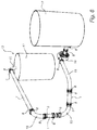
- a system 13 for transporting material in mineral processing plants The system 13 comprises four metal pipes 1, four rubber hoses 15, fifteen coupling devices 8, a pump 16 and two reservoirs 17.
Landscapes
- Engineering & Computer Science (AREA)
- General Engineering & Computer Science (AREA)
- Mechanical Engineering (AREA)
- Rigid Pipes And Flexible Pipes (AREA)
Description
- The present invention relates to a metal pipe for transporting material in mineral processing plants. The invention also relates to coupling device for coupling a first and a second transporting means, and a system for transporting material in mineral processing plants.
- When materials are crushed or pulverised in mineral processing plants several different methods can be used. During the crushing process, highly abrasive materials are to be transported throughout the processing plants. The highly abrasive materials are traditionally mixed with water and transported by transporting means consisting of rubber hoses and metal pipes which are internally coated with rubber. Rubber offers a superior wear resistance when handling this kind of abrasive materials. Normally, the rubber hoses are used in the curved portions of the transporting route and the metal pipes in the straight portions of the transporting route.
- The present invention relates to an improved metal pipe and a coupling device for simplified coupling between the different types of transporting means, primarily between metal pipes and rubber hoses or pipes such as those discussed in
US 2007/036982 A . The rubber hoses and metal pipes are today coupled to each other by attaching a coupling device at the ends of each rubber hose and a flange at the ends of each metal pipe. The flanges are welded to the outer ends of the metal pipe to be attached. The coupling devices of the rubber hoses are then attached to the flanges of the metal pipes in order to create a satisfying overall length for transportation of the material throughout the plants. The importance of creating sufficient and reliable connections between the transporting means is vital and the consequences of failure along the route of transportation would be catastrophic. - There are problems associated with the above mentioned technique of connecting the transporting means to each other. The flanges are expensive to manufacture and to attach to the metal pipes. Additionally, the transportation of the metal pipes before mounting is made difficult due to the shape of the same when the flanges have been attached.
- It is an object of the present invention to provide an improvement of the above mentioned technique and prior art. More particularly, it is an object of the present invention to provide an improved metal pipe which simplifies the coupling to other transporting means. Further, it is an object of the present invention to provide a coupling device for coupling a first and a second transporting means, and a system for transporting material in mineral processing plants.
- These and other objects as well as advantages that will be apparent from the following description of the present invention are achieved by a metal pipe, a coupling device and a system for transporting material in mineral processing plants according to the independent claims.
- A metal pipe for transporting material in mineral processing plants is provided. The metal pipe has a first and a second end portion. The metal pipe is characterised in that an outer circumferential surface of the first end portion is coated with an elastomeric coating. This is advantageous in that due to the inventive elastomeric coating, the earlier needed flanges on the metal pipe for coupling to another transporting means are no longer necessary. The same type of coupling device used for rubber hoses can now also be used for the metal pipe. The coupling device is simply attached to and surrounding the outer circumferential surface metal pipe coated with the elastomeric coating. Attachment means provided on the inner circumferential surface of the coupling device penetrate the elastomeric coating for rigid and stable coupling between the metal pipe and another transporting means. Accordingly, the problem of the expensive manufacture and attachment of the flanges to the metal pipe is eliminated. Further, the metal pipes are easier to transport when having no flanges in a dimension perspective.
- The outer circumferential surface of the second end portion may be coated with an elastomeric coating, which is advantageous in that the above mentioned advantageous now apply for both ends of the metal pipe.
- The elastomeric coating may be vulcanized onto said outer circumferential surface, which creates a satisfying and very stable attachment of the elastomeric coating to the metal pipe. Other binding methods are generally not sufficient in this type of attachment process.
- The elastomeric coating may be rubber. Rubber exhibits the required characteristics for this type of application and is accordingly a preferred material.
- The rubber may have a hardness of 50 to 80°shore A, preferably about 60°shore A, which is a preferred hardness.
- The metal pipe may be made of high-strength steel. High-strength steel exhibits the required characteristics for this type of application and is accordingly a preferred material.
- The coupling device may comprise a sleeve portion adapted to surround an outer circumferential surface of one of said transporting means, and a flange portion adapted to be connected to a corresponding flange portion of another coupling device. The coupling device is characterised in that said sleeve portion in an inner circumferential surface comprises attachment means. This is advantageous in that the same type of coupling device may be used for any type of transporting means. The coupling device is simply attached to and surrounding the outer circumferential surface metal pipe coated with the elastomeric coating. Inventive attachment means provided on the inner circumferential surface of the coupling device penetrate the elastomeric coating for rigid and stable coupling to the transporting means. Due to the fact that the same coupling device may be used for any type of transporting means, the overall costs of a transporting route comprising such transporting means is heavily decreased.
- The attachment means may be chosen from the group consisting of protrusions, recesses, wavy surfaces, and plain surfaces. Naturally, other attachment means are also possible.
- The coupling device may be dividable, which makes it easy to mount. It is accordingly also easy to detach if necessary.
- The coupling device may be made of aluminium. Aluminium exhibits the required characteristics for this type of application and is accordingly a preferred material.
- The invention may be used for transporting material in mineral processing plants. The system comprises at least a first and a second transporting means. The first transporting means is a metal pipe according to the features above and the second transporting means is chosen from the group consisting of metal pipes according to the features above and elastomeric hoses, and at least two coupling devices according to the features above. The first and second transporting means are coupled to each other at a respective end portion by means of said coupling devices.
- Generally, all terms used in the claims are to be interpreted according to their ordinary meaning in the technical field, unless explicitly defined otherwise herein. All references to "a/an/the [element, device, component, means, etc]" are to be interpreted openly as referring to at least one instance of said element, device, component, means, etc., unless explicitly stated otherwise.
- The above, as well as additional objects, features and advantages of the present invention, will be better understood through the following illustrative and non-limiting detailed description of preferred embodiments of the present invention, with reference to the appended drawings, where the same reference numerals will be used for similar elements, wherein:
-
Fig. 1 is a perspective view of one embodiment of a metal pipe used in the present invention, -
Fig. 2 is a perspective view of the metal pipe ofFig. 1 , and coupling devices according to present invention, -
Figs. 3-5 are perspective views of three different embodiments of metal pipes used in accordance with the invention, and -
Fig. 6 is a perspective view of a system making use of the present invention. -
Fig. 1 illustrates one embodiment of a metal pipe 1 for transporting material in mineral processing plants The metal pipe 1 is hollow and has a cylindrical shape. The metal pipe 1 is made of high-strength steel and has on its inner circumferential surface 2 a rubber coating 3. The rubber coating 3 offers a superior wear resistance when transporting abrasive materials. The metal pipe 1 has a having a first and asecond end portion 4, 5. The metal pipe 1 is coated with anelastomeric coating 6 on the outercircumferential surface 7 of the first andsecond end portions 4, 5. Theelastomeric coating 6 is constituted by rubber and is vulcanized onto the outercircumferential surface 7. The preferred hardness of the rubber is preferably about 70°shore A. However, theelastomeric coating 6 may naturally be of any other elastomeric material having the same or a different suitable hardness. Also, the metal pipe 1 may be made of other suitable materials than high-strength steel. - In
Fig. 2 , the metal pipe 1 is illustrated when being provided with acoupling device 8 according to a second aspect of the present invention on the first andsecond end portions 4, 5, respectively. The function of thecoupling devices 8 is to attach each of the first andsecond end portions 4, 5 of the metal pipe 1 to another transporting means. The further transporting means may for example consist of another metal pipe or a rubber hose. Thecoupling device 8 comprises a sleeve portion 9 adapted to surround the outer circumferential surface of the metal pipe 1, and aflange portion 10 adapted to be connected to a corresponding flange portion of another coupling device attached to another transporting means. The sleeve portion 9 has attachment means 11 on an innercircumferential surface 12. When thecoupling device 8 is to be attached to the metal pipe 1, it is arranged so that the sleeve portion 9 surrounds the outercircumferential surface 7 of the metal pipe 1. This way, the attachment means 11 penetrate theelastomeric coating 6 of the metal pipe 1 and thus a rigid and stable coupling to the metal pipe 1 is provided. Thecoupling device 8 is dividable for easy mounting to and detachment from the metal pipe 1. After mounting of thecoupling device 8 to the metal pipe 1, thecoupling device 8 can be coupled together with acorresponding coupling device 8 attached to another transporting means, thereby coupling the metal pipe 1 and the transporting means together. Thecoupling device 8 is preferably made of aluminium. However, other material is naturally also possible. -
Fig. 3 illustrates a second embodiment of the metal pipe 1 This embodiment comprises a branching and is used when additional transporting means are necessary. Threecoupling devices 8 are attached to the metal pipe 1. - In
Fig. 4 , a third embodiment of the metal pipe 1 is illustrated. This embodiment comprises a T-pipe and is used when additional transporting means are necessary. Threecoupling devices 8 are attached to the metal pipe 1. -
Fig. 5 illustrates a fourth embodiment of the metal pipe 1 This embodiment is used for coupling to a reservoir. Threecoupling devices 8 are attached to the metal pipe 1. - In
Fig. 6 , asystem 13 for transporting material in mineral processing plants Thesystem 13 comprises four metal pipes 1, fourrubber hoses 15, fifteencoupling devices 8, apump 16 and tworeservoirs 17. - The invention has mainly been described above with reference to a few embodiments. However, as is readily appreciated by a person skilled in the art, other embodiments than the ones disclosed above are equally possible within the scope of the invention, as defined by the appended claims. Accordingly, the size and shape of the metal pipe, the coupling device and the system according to the present invention may be varied in a vast number of different embodiments without deviating from the scope of the invention.
Claims (5)
- Metal pipe (1) for transporting material in mineral processing plants, said metal pipe (1) having a first and a second end portion (4, 5), wherein an outer circumferential surface (7) of said first and second end portions (4, 5) is coated with an elastomeric coating (6) adapted to receive an attachment means (11) of a coupling device (8),
wherein an inner circumferential surface (2) of said metal pipe (1) is coated with an elastomeric coating (3) adapted to resist wear during transport of said material;
characterized in that said outer circumferential surface (7), between said first and second end portions (4, 5), is free from said elastomeric coating (6); and
a coupling device (8) is attached to at least one of said first and second end portion (4, 5) and surrounds the outer circumferential surface (7) of the metal pipe (1) coated with elastomeric coating, wherein said coupling device (8) comprises a sleeve portion (9) surrounding said outer circumferential surface (7), and a flange portion (10) adapted to be connected to a corresponding flange or another coupling device, and wherein attachment means (11) are provided on the inner circumferential surface (12) of the coupling device (8) adapted to penetrate the elastomeric coating (6) for rigid and stable attachment between said coupling device (8) and said pipe (1). - Metal pipe (1) according to claim 1, wherein said elastomeric coating (6) is vulcanized onto said outer circumferential surface (7).
- Metal pipe (1) according to any one of the preceding claims, wherein said elastomeric coating (6) is rubber.
- Metal pipe (1) according to claim 3, wherein said rubber has a hardness of 50 to 80°shore A, preferably about 60°shore A.
- Metal pipe (1) according to any one of the preceding claims, wherein said metal pipe (1) is made of high-strength steel.
Applications Claiming Priority (1)
| Application Number | Priority Date | Filing Date | Title |
|---|---|---|---|
| PCT/EP2010/068525 WO2012072113A1 (en) | 2010-11-30 | 2010-11-30 | Metal pipe having an elastomeric coating, a coupling device and a system for transporting material in mineral processing plants |
Publications (2)
| Publication Number | Publication Date |
|---|---|
| EP2646727A1 EP2646727A1 (en) | 2013-10-09 |
| EP2646727B1 true EP2646727B1 (en) | 2016-07-06 |
Family
ID=44275703
Family Applications (1)
| Application Number | Title | Priority Date | Filing Date |
|---|---|---|---|
| EP10787093.3A Active EP2646727B1 (en) | 2010-11-30 | 2010-11-30 | Metal pipe having an elastomeric coating |
Country Status (6)
| Country | Link |
|---|---|
| EP (1) | EP2646727B1 (en) |
| CN (1) | CN103384790B (en) |
| AU (1) | AU2010364696B2 (en) |
| DK (1) | DK2646727T3 (en) |
| RU (1) | RU2563045C2 (en) |
| WO (1) | WO2012072113A1 (en) |
Families Citing this family (2)
| Publication number | Priority date | Publication date | Assignee | Title |
|---|---|---|---|---|
| JP2016211712A (en) * | 2015-05-13 | 2016-12-15 | 三菱樹脂インフラテック株式会社 | Flanged joint member and connection structure thereof |
| FI131207B1 (en) * | 2023-11-17 | 2024-12-03 | Proweon Oy | A connecting arrangement for a hose |
Citations (1)
| Publication number | Priority date | Publication date | Assignee | Title |
|---|---|---|---|---|
| US20070036982A1 (en) * | 2005-08-11 | 2007-02-15 | 3M Innovative Properties Company | Interpenetrating polymer network as coating for metal substrate and method therefor |
Family Cites Families (13)
| Publication number | Priority date | Publication date | Assignee | Title |
|---|---|---|---|---|
| US2044900A (en) * | 1930-03-03 | 1936-06-23 | Chicago Tubing & Braiding Comp | Flexible metal tube |
| US2865094A (en) * | 1954-10-04 | 1958-12-23 | Resistoflex Corp | Method of securing a coupling to an end of a high temperature flexible hose |
| US3891291A (en) * | 1974-02-05 | 1975-06-24 | Wiggins Inc E B | Tubing coupling incorporating bridging conductor |
| US4293150A (en) * | 1977-01-17 | 1981-10-06 | Resistoflex Corporation | Fluid conduit assembly |
| FR2384195A3 (en) * | 1977-09-12 | 1978-10-13 | Trelleborgs Gummifabriks Ab | Rigid joint assembly for flexible pipes - has two flanged half-shells with sheet metal liner having pipe-gripping projections |
| DE3742335A1 (en) * | 1987-12-14 | 1989-06-22 | Karl Quaschner | ELASTOMER TAPE WITH INTEGRATED PRINT POINT GRANULES |
| DE4018753A1 (en) * | 1990-06-12 | 1991-12-19 | Platzer Schwedenbau Gmbh | Multilayer tube - has protective layer round leak-proof tube sealed in place by clinging material |
| WO1995024578A1 (en) * | 1994-03-10 | 1995-09-14 | Elf Atochem S.A. | Flexible metal pipes comprising a retractable polymer sheath |
| GB2290743B (en) * | 1994-07-01 | 1997-12-10 | Draftex Ind Ltd | Pipes for fluid flow and methods of making them |
| JP3392988B2 (en) * | 1995-06-22 | 2003-03-31 | コスモ工機株式会社 | Captive fittings |
| IT1319088B1 (en) * | 2000-11-08 | 2003-09-23 | Alfagomma S P A | FITTING FOR INTERNALLY COATED PIPES AND PROCEDURE FOR SUAMESSA IN WORK |
| CA2647213A1 (en) * | 2006-04-04 | 2007-10-18 | Putzmeister Concrete Pumps Gmbh | Transport tube for thick materials |
| RU66469U1 (en) * | 2007-02-05 | 2007-09-10 | Государственное образовательное учреждение высшего профессионального образования "Курский государственный технический университет" | FLEXIBLE PIPELINE WITH FLANGES |
-
2010
- 2010-11-30 WO PCT/EP2010/068525 patent/WO2012072113A1/en not_active Ceased
- 2010-11-30 DK DK10787093.3T patent/DK2646727T3/en active
- 2010-11-30 AU AU2010364696A patent/AU2010364696B2/en active Active
- 2010-11-30 EP EP10787093.3A patent/EP2646727B1/en active Active
- 2010-11-30 CN CN201080071137.6A patent/CN103384790B/en active Active
- 2010-11-30 RU RU2013126381/06A patent/RU2563045C2/en active
Patent Citations (1)
| Publication number | Priority date | Publication date | Assignee | Title |
|---|---|---|---|---|
| US20070036982A1 (en) * | 2005-08-11 | 2007-02-15 | 3M Innovative Properties Company | Interpenetrating polymer network as coating for metal substrate and method therefor |
Also Published As
| Publication number | Publication date |
|---|---|
| AU2010364696B2 (en) | 2015-05-21 |
| RU2013126381A (en) | 2015-01-10 |
| RU2563045C2 (en) | 2015-09-20 |
| EP2646727A1 (en) | 2013-10-09 |
| CN103384790B (en) | 2016-11-02 |
| AU2010364696A1 (en) | 2013-05-09 |
| DK2646727T3 (en) | 2016-10-24 |
| WO2012072113A1 (en) | 2012-06-07 |
| CN103384790A (en) | 2013-11-06 |
Similar Documents
| Publication | Publication Date | Title |
|---|---|---|
| US20100228295A1 (en) | Variable Radius Vertebra Bend Restrictor | |
| US10378682B2 (en) | High pressure pipe coupling construction, as well as method for forming said coupling construction | |
| EP1867905B1 (en) | Radius control | |
| US9334993B2 (en) | Connecting structure comprising a high-pressure pipeline and coupling | |
| EP1033518A1 (en) | Pipe coupling | |
| US20090320223A1 (en) | Multi-diameter elastic sealing module for pigs | |
| GB2439146A (en) | Pipe coupling | |
| US6874542B2 (en) | Flexible hose with connect flange and method for obtaining same | |
| CN103946615B (en) | Flexible pipe and the use of flexible duct for conveying grinding material slurry | |
| AU2010364696B2 (en) | Metal pipe having an elastomeric coating, a coupling device and a system for transporting material in mineral processing plants | |
| EP0913622A2 (en) | Pipe coupling | |
| US6305476B1 (en) | Deep well flexible hose and method of use | |
| US9291287B2 (en) | Conduit displacement mitigation apparatus including mesh layers, methods and systems for use with subsea conduits | |
| EA014086B1 (en) | Method of joining a pair of tubular ends | |
| EP2855992B1 (en) | Pipe for abrasive materials, such as concrete or similar materials, and method of production | |
| CN212361075U (en) | Anti-static chemical anti-corrosion pipeline | |
| EP2643631A1 (en) | Pipeline for conveying liquefied gas | |
| WO2006045484A1 (en) | Delivery pipe for transporting solids | |
| CN110506178A (en) | Marine hose | |
| US9829131B2 (en) | Pipe coupling construction, and coupling | |
| US20060131872A1 (en) | Reinforced fitting and pipe | |
| CN108006335A (en) | A kind of abrasive rubber hose and its preparation process | |
| WO2025104366A1 (en) | A connecting arrangement for a hose | |
| CN210291070U (en) | Pipe connector | |
| CN104197125A (en) | High-flexibility composite tube |
Legal Events
| Date | Code | Title | Description |
|---|---|---|---|
| PUAI | Public reference made under article 153(3) epc to a published international application that has entered the european phase |
Free format text: ORIGINAL CODE: 0009012 |
|
| 17P | Request for examination filed |
Effective date: 20130529 |
|
| AK | Designated contracting states |
Kind code of ref document: A1 Designated state(s): AL AT BE BG CH CY CZ DE DK EE ES FI FR GB GR HR HU IE IS IT LI LT LU LV MC MK MT NL NO PL PT RO RS SE SI SK SM TR |
|
| DAX | Request for extension of the european patent (deleted) | ||
| 17Q | First examination report despatched |
Effective date: 20140321 |
|
| REG | Reference to a national code |
Ref country code: DE Ref legal event code: R079 Ref document number: 602010034532 Country of ref document: DE Free format text: PREVIOUS MAIN CLASS: F16L0009147000 Ipc: F16L0057060000 |
|
| GRAP | Despatch of communication of intention to grant a patent |
Free format text: ORIGINAL CODE: EPIDOSNIGR1 |
|
| RIC1 | Information provided on ipc code assigned before grant |
Ipc: F16L 9/147 20060101ALI20160112BHEP Ipc: F16L 23/024 20060101ALI20160112BHEP Ipc: F16L 57/06 20060101AFI20160112BHEP |
|
| INTG | Intention to grant announced |
Effective date: 20160129 |
|
| GRAS | Grant fee paid |
Free format text: ORIGINAL CODE: EPIDOSNIGR3 |
|
| GRAA | (expected) grant |
Free format text: ORIGINAL CODE: 0009210 |
|
| AK | Designated contracting states |
Kind code of ref document: B1 Designated state(s): AL AT BE BG CH CY CZ DE DK EE ES FI FR GB GR HR HU IE IS IT LI LT LU LV MC MK MT NL NO PL PT RO RS SE SI SK SM TR |
|
| REG | Reference to a national code |
Ref country code: GB Ref legal event code: FG4D |
|
| REG | Reference to a national code |
Ref country code: AT Ref legal event code: REF Ref document number: 810976 Country of ref document: AT Kind code of ref document: T Effective date: 20160715 Ref country code: CH Ref legal event code: EP |
|
| REG | Reference to a national code |
Ref country code: IE Ref legal event code: FG4D |
|
| REG | Reference to a national code |
Ref country code: DE Ref legal event code: R096 Ref document number: 602010034532 Country of ref document: DE |
|
| REG | Reference to a national code |
Ref country code: NL Ref legal event code: FP |
|
| REG | Reference to a national code |
Ref country code: DK Ref legal event code: T3 Effective date: 20161021 |
|
| REG | Reference to a national code |
Ref country code: SE Ref legal event code: TRGR |
|
| REG | Reference to a national code |
Ref country code: FR Ref legal event code: PLFP Year of fee payment: 7 |
|
| REG | Reference to a national code |
Ref country code: LT Ref legal event code: MG4D |
|
| REG | Reference to a national code |
Ref country code: NO Ref legal event code: T2 Effective date: 20160706 |
|
| REG | Reference to a national code |
Ref country code: AT Ref legal event code: MK05 Ref document number: 810976 Country of ref document: AT Kind code of ref document: T Effective date: 20160706 |
|
| PG25 | Lapsed in a contracting state [announced via postgrant information from national office to epo] |
Ref country code: IT Free format text: LAPSE BECAUSE OF FAILURE TO SUBMIT A TRANSLATION OF THE DESCRIPTION OR TO PAY THE FEE WITHIN THE PRESCRIBED TIME-LIMIT Effective date: 20160706 Ref country code: HR Free format text: LAPSE BECAUSE OF FAILURE TO SUBMIT A TRANSLATION OF THE DESCRIPTION OR TO PAY THE FEE WITHIN THE PRESCRIBED TIME-LIMIT Effective date: 20160706 Ref country code: LT Free format text: LAPSE BECAUSE OF FAILURE TO SUBMIT A TRANSLATION OF THE DESCRIPTION OR TO PAY THE FEE WITHIN THE PRESCRIBED TIME-LIMIT Effective date: 20160706 Ref country code: IS Free format text: LAPSE BECAUSE OF FAILURE TO SUBMIT A TRANSLATION OF THE DESCRIPTION OR TO PAY THE FEE WITHIN THE PRESCRIBED TIME-LIMIT Effective date: 20161106 Ref country code: RS Free format text: LAPSE BECAUSE OF FAILURE TO SUBMIT A TRANSLATION OF THE DESCRIPTION OR TO PAY THE FEE WITHIN THE PRESCRIBED TIME-LIMIT Effective date: 20160706 |
|
| PG25 | Lapsed in a contracting state [announced via postgrant information from national office to epo] |
Ref country code: GR Free format text: LAPSE BECAUSE OF FAILURE TO SUBMIT A TRANSLATION OF THE DESCRIPTION OR TO PAY THE FEE WITHIN THE PRESCRIBED TIME-LIMIT Effective date: 20161007 Ref country code: BE Free format text: LAPSE BECAUSE OF NON-PAYMENT OF DUE FEES Effective date: 20160706 Ref country code: AT Free format text: LAPSE BECAUSE OF FAILURE TO SUBMIT A TRANSLATION OF THE DESCRIPTION OR TO PAY THE FEE WITHIN THE PRESCRIBED TIME-LIMIT Effective date: 20160706 Ref country code: LV Free format text: LAPSE BECAUSE OF FAILURE TO SUBMIT A TRANSLATION OF THE DESCRIPTION OR TO PAY THE FEE WITHIN THE PRESCRIBED TIME-LIMIT Effective date: 20160706 Ref country code: PL Free format text: LAPSE BECAUSE OF FAILURE TO SUBMIT A TRANSLATION OF THE DESCRIPTION OR TO PAY THE FEE WITHIN THE PRESCRIBED TIME-LIMIT Effective date: 20160706 Ref country code: ES Free format text: LAPSE BECAUSE OF FAILURE TO SUBMIT A TRANSLATION OF THE DESCRIPTION OR TO PAY THE FEE WITHIN THE PRESCRIBED TIME-LIMIT Effective date: 20160706 Ref country code: PT Free format text: LAPSE BECAUSE OF FAILURE TO SUBMIT A TRANSLATION OF THE DESCRIPTION OR TO PAY THE FEE WITHIN THE PRESCRIBED TIME-LIMIT Effective date: 20161107 |
|
| REG | Reference to a national code |
Ref country code: DE Ref legal event code: R097 Ref document number: 602010034532 Country of ref document: DE |
|
| PG25 | Lapsed in a contracting state [announced via postgrant information from national office to epo] |
Ref country code: RO Free format text: LAPSE BECAUSE OF FAILURE TO SUBMIT A TRANSLATION OF THE DESCRIPTION OR TO PAY THE FEE WITHIN THE PRESCRIBED TIME-LIMIT Effective date: 20160706 Ref country code: EE Free format text: LAPSE BECAUSE OF FAILURE TO SUBMIT A TRANSLATION OF THE DESCRIPTION OR TO PAY THE FEE WITHIN THE PRESCRIBED TIME-LIMIT Effective date: 20160706 |
|
| PLBE | No opposition filed within time limit |
Free format text: ORIGINAL CODE: 0009261 |
|
| STAA | Information on the status of an ep patent application or granted ep patent |
Free format text: STATUS: NO OPPOSITION FILED WITHIN TIME LIMIT |
|
| PG25 | Lapsed in a contracting state [announced via postgrant information from national office to epo] |
Ref country code: BG Free format text: LAPSE BECAUSE OF FAILURE TO SUBMIT A TRANSLATION OF THE DESCRIPTION OR TO PAY THE FEE WITHIN THE PRESCRIBED TIME-LIMIT Effective date: 20161006 Ref country code: SK Free format text: LAPSE BECAUSE OF FAILURE TO SUBMIT A TRANSLATION OF THE DESCRIPTION OR TO PAY THE FEE WITHIN THE PRESCRIBED TIME-LIMIT Effective date: 20160706 Ref country code: CZ Free format text: LAPSE BECAUSE OF FAILURE TO SUBMIT A TRANSLATION OF THE DESCRIPTION OR TO PAY THE FEE WITHIN THE PRESCRIBED TIME-LIMIT Effective date: 20160706 Ref country code: SM Free format text: LAPSE BECAUSE OF FAILURE TO SUBMIT A TRANSLATION OF THE DESCRIPTION OR TO PAY THE FEE WITHIN THE PRESCRIBED TIME-LIMIT Effective date: 20160706 |
|
| 26N | No opposition filed |
Effective date: 20170407 |
|
| REG | Reference to a national code |
Ref country code: CH Ref legal event code: PL |
|
| PG25 | Lapsed in a contracting state [announced via postgrant information from national office to epo] |
Ref country code: LI Free format text: LAPSE BECAUSE OF NON-PAYMENT OF DUE FEES Effective date: 20161130 Ref country code: CH Free format text: LAPSE BECAUSE OF NON-PAYMENT OF DUE FEES Effective date: 20161130 |
|
| REG | Reference to a national code |
Ref country code: IE Ref legal event code: MM4A |
|
| PG25 | Lapsed in a contracting state [announced via postgrant information from national office to epo] |
Ref country code: SI Free format text: LAPSE BECAUSE OF FAILURE TO SUBMIT A TRANSLATION OF THE DESCRIPTION OR TO PAY THE FEE WITHIN THE PRESCRIBED TIME-LIMIT Effective date: 20160706 |
|
| PG25 | Lapsed in a contracting state [announced via postgrant information from national office to epo] |
Ref country code: LU Free format text: LAPSE BECAUSE OF NON-PAYMENT OF DUE FEES Effective date: 20161130 |
|
| REG | Reference to a national code |
Ref country code: FR Ref legal event code: PLFP Year of fee payment: 8 |
|
| PG25 | Lapsed in a contracting state [announced via postgrant information from national office to epo] |
Ref country code: IE Free format text: LAPSE BECAUSE OF NON-PAYMENT OF DUE FEES Effective date: 20161130 |
|
| PG25 | Lapsed in a contracting state [announced via postgrant information from national office to epo] |
Ref country code: HU Free format text: LAPSE BECAUSE OF FAILURE TO SUBMIT A TRANSLATION OF THE DESCRIPTION OR TO PAY THE FEE WITHIN THE PRESCRIBED TIME-LIMIT; INVALID AB INITIO Effective date: 20101130 Ref country code: CY Free format text: LAPSE BECAUSE OF FAILURE TO SUBMIT A TRANSLATION OF THE DESCRIPTION OR TO PAY THE FEE WITHIN THE PRESCRIBED TIME-LIMIT Effective date: 20160706 |
|
| PG25 | Lapsed in a contracting state [announced via postgrant information from national office to epo] |
Ref country code: MC Free format text: LAPSE BECAUSE OF FAILURE TO SUBMIT A TRANSLATION OF THE DESCRIPTION OR TO PAY THE FEE WITHIN THE PRESCRIBED TIME-LIMIT Effective date: 20160706 Ref country code: MK Free format text: LAPSE BECAUSE OF FAILURE TO SUBMIT A TRANSLATION OF THE DESCRIPTION OR TO PAY THE FEE WITHIN THE PRESCRIBED TIME-LIMIT Effective date: 20160706 |
|
| PG25 | Lapsed in a contracting state [announced via postgrant information from national office to epo] |
Ref country code: MT Free format text: LAPSE BECAUSE OF NON-PAYMENT OF DUE FEES Effective date: 20161130 |
|
| REG | Reference to a national code |
Ref country code: FR Ref legal event code: PLFP Year of fee payment: 9 |
|
| PG25 | Lapsed in a contracting state [announced via postgrant information from national office to epo] |
Ref country code: AL Free format text: LAPSE BECAUSE OF FAILURE TO SUBMIT A TRANSLATION OF THE DESCRIPTION OR TO PAY THE FEE WITHIN THE PRESCRIBED TIME-LIMIT Effective date: 20160706 Ref country code: TR Free format text: LAPSE BECAUSE OF FAILURE TO SUBMIT A TRANSLATION OF THE DESCRIPTION OR TO PAY THE FEE WITHIN THE PRESCRIBED TIME-LIMIT Effective date: 20160706 |
|
| REG | Reference to a national code |
Ref country code: NL Ref legal event code: HC Owner name: METSO SWEDEN AB; SE Free format text: DETAILS ASSIGNMENT: CHANGE OF OWNER(S), CHANGE OF OWNER(S) NAME; FORMER OWNER NAME: METSO MINERALS (SWEDEN) AB Effective date: 20220926 |
|
| REG | Reference to a national code |
Ref country code: NO Ref legal event code: CHAD Owner name: METSO OUTOTEC SWEDEN AB, PO BOX 132, SVERIGE |
|
| REG | Reference to a national code |
Ref country code: NL Ref legal event code: HC Owner name: METSO OUTOTEC SWEDEN AB; SE Free format text: DETAILS ASSIGNMENT: CHANGE OF OWNER(S), CHANGE OF OWNER(S) NAME; FORMER OWNER NAME: METSO SWEDEN AB Effective date: 20221019 |
|
| REG | Reference to a national code |
Ref country code: DE Ref legal event code: R081 Ref document number: 602010034532 Country of ref document: DE Owner name: METSO OUTOTEC SWEDEN AB, SE Free format text: FORMER OWNER: METSO MINERALS (SWEDEN) AB, TRELLEBORG, SE Ref country code: DE Ref legal event code: R081 Ref document number: 602010034532 Country of ref document: DE Owner name: METSO SWEDEN AB, SE Free format text: FORMER OWNER: METSO MINERALS (SWEDEN) AB, TRELLEBORG, SE |
|
| P01 | Opt-out of the competence of the unified patent court (upc) registered |
Effective date: 20230527 |
|
| REG | Reference to a national code |
Ref country code: DE Ref legal event code: R081 Ref document number: 602010034532 Country of ref document: DE Owner name: METSO SWEDEN AB, SE Free format text: FORMER OWNER: METSO OUTOTEC SWEDEN AB, TRELLEBORG, SE |
|
| PGFP | Annual fee paid to national office [announced via postgrant information from national office to epo] |
Ref country code: NL Payment date: 20251015 Year of fee payment: 16 |
|
| PGFP | Annual fee paid to national office [announced via postgrant information from national office to epo] |
Ref country code: DE Payment date: 20251007 Year of fee payment: 16 |
|
| PGFP | Annual fee paid to national office [announced via postgrant information from national office to epo] |
Ref country code: GB Payment date: 20251016 Year of fee payment: 16 |
|
| PGFP | Annual fee paid to national office [announced via postgrant information from national office to epo] |
Ref country code: NO Payment date: 20251113 Year of fee payment: 16 |
|
| PGFP | Annual fee paid to national office [announced via postgrant information from national office to epo] |
Ref country code: FI Payment date: 20251113 Year of fee payment: 16 Ref country code: DK Payment date: 20251112 Year of fee payment: 16 |
|
| PGFP | Annual fee paid to national office [announced via postgrant information from national office to epo] |
Ref country code: FR Payment date: 20251023 Year of fee payment: 16 |
|
| PGFP | Annual fee paid to national office [announced via postgrant information from national office to epo] |
Ref country code: SE Payment date: 20251010 Year of fee payment: 16 |
|
| REG | Reference to a national code |
Ref country code: NL Ref legal event code: HC Owner name: METSO SWEDEN AB; SE Free format text: DETAILS ASSIGNMENT: CHANGE OF OWNER(S), CHANGE OF OWNER(S) NAME; FORMER OWNER NAME: METSO SWEDEN AB Effective date: 20260311 |