EP2646129B1 - Multi-chambered hydroclone - Google Patents
Multi-chambered hydroclone Download PDFInfo
- Publication number
- EP2646129B1 EP2646129B1 EP12782820.0A EP12782820A EP2646129B1 EP 2646129 B1 EP2646129 B1 EP 2646129B1 EP 12782820 A EP12782820 A EP 12782820A EP 2646129 B1 EP2646129 B1 EP 2646129B1
- Authority
- EP
- European Patent Office
- Prior art keywords
- effluent
- fluid
- vortex
- chamber
- barrier
- Prior art date
- Legal status (The legal status is an assumption and is not a legal conclusion. Google has not performed a legal analysis and makes no representation as to the accuracy of the status listed.)
- Active
Links
Images





Classifications
-
- B—PERFORMING OPERATIONS; TRANSPORTING
- B01—PHYSICAL OR CHEMICAL PROCESSES OR APPARATUS IN GENERAL
- B01D—SEPARATION
- B01D36/00—Filter circuits or combinations of filters with other separating devices
- B01D36/04—Combinations of filters with settling tanks
- B01D36/045—Combination of filters with centrifugal separation devices
-
- B—PERFORMING OPERATIONS; TRANSPORTING
- B01—PHYSICAL OR CHEMICAL PROCESSES OR APPARATUS IN GENERAL
- B01D—SEPARATION
- B01D36/00—Filter circuits or combinations of filters with other separating devices
-
- B—PERFORMING OPERATIONS; TRANSPORTING
- B01—PHYSICAL OR CHEMICAL PROCESSES OR APPARATUS IN GENERAL
- B01D—SEPARATION
- B01D21/00—Separation of suspended solid particles from liquids by sedimentation
- B01D21/0006—Settling tanks provided with means for cleaning and maintenance
-
- B—PERFORMING OPERATIONS; TRANSPORTING
- B01—PHYSICAL OR CHEMICAL PROCESSES OR APPARATUS IN GENERAL
- B01D—SEPARATION
- B01D21/00—Separation of suspended solid particles from liquids by sedimentation
- B01D21/0012—Settling tanks making use of filters, e.g. by floating layers of particulate material
-
- B—PERFORMING OPERATIONS; TRANSPORTING
- B01—PHYSICAL OR CHEMICAL PROCESSES OR APPARATUS IN GENERAL
- B01D—SEPARATION
- B01D21/00—Separation of suspended solid particles from liquids by sedimentation
- B01D21/26—Separation of sediment aided by centrifugal force or centripetal force
-
- B—PERFORMING OPERATIONS; TRANSPORTING
- B01—PHYSICAL OR CHEMICAL PROCESSES OR APPARATUS IN GENERAL
- B01D—SEPARATION
- B01D21/00—Separation of suspended solid particles from liquids by sedimentation
- B01D21/26—Separation of sediment aided by centrifugal force or centripetal force
- B01D21/267—Separation of sediment aided by centrifugal force or centripetal force by using a cyclone
-
- B—PERFORMING OPERATIONS; TRANSPORTING
- B01—PHYSICAL OR CHEMICAL PROCESSES OR APPARATUS IN GENERAL
- B01D—SEPARATION
- B01D29/00—Filters with filtering elements stationary during filtration, e.g. pressure or suction filters, not covered by groups B01D24/00 - B01D27/00; Filtering elements therefor
- B01D29/62—Regenerating the filter material in the filter
- B01D29/64—Regenerating the filter material in the filter by scrapers, brushes, nozzles, or the like, acting on the cake side of the filtering element
- B01D29/6407—Regenerating the filter material in the filter by scrapers, brushes, nozzles, or the like, acting on the cake side of the filtering element brushes
- B01D29/6415—Regenerating the filter material in the filter by scrapers, brushes, nozzles, or the like, acting on the cake side of the filtering element brushes with a rotary movement with respect to the filtering element
-
- B—PERFORMING OPERATIONS; TRANSPORTING
- B01—PHYSICAL OR CHEMICAL PROCESSES OR APPARATUS IN GENERAL
- B01D—SEPARATION
- B01D29/00—Filters with filtering elements stationary during filtration, e.g. pressure or suction filters, not covered by groups B01D24/00 - B01D27/00; Filtering elements therefor
- B01D29/88—Filters with filtering elements stationary during filtration, e.g. pressure or suction filters, not covered by groups B01D24/00 - B01D27/00; Filtering elements therefor having feed or discharge devices
- B01D29/90—Filters with filtering elements stationary during filtration, e.g. pressure or suction filters, not covered by groups B01D24/00 - B01D27/00; Filtering elements therefor having feed or discharge devices for feeding
- B01D29/908—Filters with filtering elements stationary during filtration, e.g. pressure or suction filters, not covered by groups B01D24/00 - B01D27/00; Filtering elements therefor having feed or discharge devices for feeding provoking a tangential stream
-
- B—PERFORMING OPERATIONS; TRANSPORTING
- B04—CENTRIFUGAL APPARATUS OR MACHINES FOR CARRYING-OUT PHYSICAL OR CHEMICAL PROCESSES
- B04C—APPARATUS USING FREE VORTEX FLOW, e.g. CYCLONES
- B04C5/00—Apparatus in which the axial direction of the vortex is reversed
- B04C5/08—Vortex chamber constructions
- B04C5/103—Bodies or members, e.g. bulkheads, guides, in the vortex chamber
-
- B—PERFORMING OPERATIONS; TRANSPORTING
- B04—CENTRIFUGAL APPARATUS OR MACHINES FOR CARRYING-OUT PHYSICAL OR CHEMICAL PROCESSES
- B04C—APPARATUS USING FREE VORTEX FLOW, e.g. CYCLONES
- B04C5/00—Apparatus in which the axial direction of the vortex is reversed
- B04C5/14—Construction of the underflow ducting; Apex constructions; Discharge arrangements ; discharge through sidewall provided with a few slits or perforations
-
- B—PERFORMING OPERATIONS; TRANSPORTING
- B04—CENTRIFUGAL APPARATUS OR MACHINES FOR CARRYING-OUT PHYSICAL OR CHEMICAL PROCESSES
- B04C—APPARATUS USING FREE VORTEX FLOW, e.g. CYCLONES
- B04C5/00—Apparatus in which the axial direction of the vortex is reversed
- B04C5/14—Construction of the underflow ducting; Apex constructions; Discharge arrangements ; discharge through sidewall provided with a few slits or perforations
- B04C5/181—Bulkheads or central bodies in the discharge opening
-
- B—PERFORMING OPERATIONS; TRANSPORTING
- B04—CENTRIFUGAL APPARATUS OR MACHINES FOR CARRYING-OUT PHYSICAL OR CHEMICAL PROCESSES
- B04C—APPARATUS USING FREE VORTEX FLOW, e.g. CYCLONES
- B04C5/00—Apparatus in which the axial direction of the vortex is reversed
- B04C5/22—Apparatus in which the axial direction of the vortex is reversed with cleaning means
-
- B—PERFORMING OPERATIONS; TRANSPORTING
- B04—CENTRIFUGAL APPARATUS OR MACHINES FOR CARRYING-OUT PHYSICAL OR CHEMICAL PROCESSES
- B04C—APPARATUS USING FREE VORTEX FLOW, e.g. CYCLONES
- B04C9/00—Combinations with other devices, e.g. fans, expansion chambers, diffusors, water locks
-
- B—PERFORMING OPERATIONS; TRANSPORTING
- B01—PHYSICAL OR CHEMICAL PROCESSES OR APPARATUS IN GENERAL
- B01D—SEPARATION
- B01D2201/00—Details relating to filtering apparatus
- B01D2201/58—Power supply means for regenerating the filter
- B01D2201/583—Power supply means for regenerating the filter using the kinetic energy of the fluid circulating in the filtering device
-
- B—PERFORMING OPERATIONS; TRANSPORTING
- B04—CENTRIFUGAL APPARATUS OR MACHINES FOR CARRYING-OUT PHYSICAL OR CHEMICAL PROCESSES
- B04C—APPARATUS USING FREE VORTEX FLOW, e.g. CYCLONES
- B04C9/00—Combinations with other devices, e.g. fans, expansion chambers, diffusors, water locks
- B04C2009/004—Combinations with other devices, e.g. fans, expansion chambers, diffusors, water locks with internal filters, in the cyclone chamber or in the vortex finder
Definitions
- the invention is generally directed toward hydroclones and cyclonic separation of fluids.
- Hydroclones are commonly used to separate suspended particles from liquids.
- pressurized feed liquid e.g. waste water
- feed liquid is introduced into a conically shaped chamber under conditions that create a vortex within the chamber.
- feed liquid is introduced near the top of a conical chamber and an effluent stream is discharged near the bottom of the chamber.
- Centrifugal forces associated with the vortex urge denser particles towards the periphery of the chamber.
- liquid located near the center of the vortex has a lower concentration of particles than that at the periphery. This "cleaner" liquid can then be withdrawn from a central region of the hydroclone.
- hydroclones are described in: US3061098 , US3529724 , US5104520 , US5407584 and US5478484 .
- Separation efficiency can be improved by including a filter within the chamber such that a portion of the liquid moving to the center of the chamber passes through the filter.
- cyclonic separation is combined with cross-flow filtration.
- Examples of such embodiments are described in: US7632416 , US7896169 , US2011/0120959 , US2012/0010063 and US 2007/0039900 . While such hybrid designs improve separation efficiency, further improvements are desired.
- the entire subject matter of each of the previously cited references is incorporated herein by reference.
- the invention includes multiple embodiments of hydroclones and methods for performing cyclonic separations using the same.
- the invention includes a hydroclone (10) having a tank (12) including a fluid inlet (14), a filtered fluid outlet (16), an effluent outlet (18), a process fluid outlet (20) and an inner peripheral wall (22) enclosing a plurality of vertically aligned chambers. While differing numbers of chambers may be used, in one embodiment the tank (12) includes three vertically aligned chambers including a vortex chamber (24) in fluid communication with the fluid inlet (14). A filter assembly (26) is located within the vortex chamber (24) and encloses a filtrate chamber (66).
- the vortex chamber (24) includes a fluid pathway (28) adapted for receiving incoming fluid and generating a vortex fluid flow about the filter assembly (26).
- the filtrate chamber (56) is in fluid communication with the filtered fluid outlet (16) such that fluid passing through the filter assembly (26) enters the filtrate chamber (56) and may exit the tank (12) by way of the filtered fluid outlet (16).
- An effluent separation chamber (30) is located below and in fluid communication with the vortex chamber (24) and is adapted for receiving unfiltered fluid from the vortex chamber (24).
- a process fluid chamber (32) is located below and in fluid communication with the effluent separation chamber (30) and is adapted for receiving a process fluid from the effluent separation chamber (30) wherein the process fluid chamber (32) is in fluid communication with the process fluid outlet (20) by which process fluid may exit the tank (12).
- a vortex flow barrier (34) is located between the vortex and effluent separation chambers (24, 30) and disrupts vortex fluid flow from the vortex chamber (24) to the effluent separation chamber (30).
- An effluent barrier (36) is located below the effluent separation chamber (30) and directs fluid flow from the effluent separation chamber (30) to the process fluid outlet (20), and wherein the effluent barrier (36) further comprises a centrally located effluent opening (38) in fluid communication with the effluent outlet (18) by which effluent exits the tank (12).
- the present invention generally relates to the hydroclone filtration devices and related methods of conducting cyclonic separation.
- the term "hydroclone” refers to a filtration device that at least partially relies upon centrifugal forces generated by vortex fluid flow to separate constituents from a fluid mixture. Examples include the separation of solid particles from a liquid mixture and separation of mixtures including liquids of differing densities (e.g. oil and water). Specific applications include the treatment of: pulp effluent generating by paper mills, process water generated by oil and gas recovery, bilge water and municipal and industrial waste water.
- FIGS 1-3 One embodiment of the invention is illustrated in Figures 1-3 including a hydroclone generally shown at 10 including a tank (12) having a removable lid (13), a fluid inlet (14), a filtered fluid outlet (16), an effluent outlet (18), a process fluid outlet (20) and an inner peripheral wall (22) enclosing a plurality of vertically aligned chambers (24, 30, 32). While depicted as including three vertically aligned chambers, additional chambers may also be included. Similarly, additional fluid inlets and outlets may also be included. While shown as having a cylindrical upper section and a frustro-conical base, the tank (12) may have other configurations including an entirely cylindrical shape as will be described in connection with Figures 8 and 9 .
- the tank (12) includes a vortex chamber (24) in fluid communication with the fluid inlet (14).
- a filter assembly (26) is centrally located within the vortex chamber (24) and encloses a filtrate chamber (66), (as best shown in Figure 7A ).
- the filtrate chamber (56) is in fluid communication with the filtered fluid outlet (16).
- An effluent separation chamber (30) is located below and is in fluid communication with the vortex chamber (24).
- the effluent separation chamber (30) is adapted for receiving unfiltered fluid from the vortex chamber (24).
- a process fluid chamber (32) is in turn located below and is in fluid communication with the effluent separation chamber (30).
- the process fluid chamber (32) is adapted for receiving a process fluid from the effluent separation chamber (30) and is in fluid communication with the process fluid outlet (20) by which process fluid may exit the tank (12).
- a vortex flow barrier (34) is located between the vortex and effluent separation chambers (24, 30) and directs fluid flow between the vortex and effluent separation (24, 30) chambers to locations adjacent to the inner peripheral wall (22) of the tank (12).
- the vortex flow barrier (34) may be designed to maintain vortex fluid flow in the effluent separation chamber (24) and disrupt vortex fluid flow (28) as fluid flows from the vortex chamber (24) into the effluent separation chamber (30).
- the vortex flow barrier (34) includes an outer periphery (40) extending to locations adjacent to or in contact with the inner peripheral wall (22) of the tank (12) and may further include a plurality of apertures (42) located near the periphery (40) and extending therethrough.
- the apertures (42) are scalloped-shaped but alternative shapes may also be used (as best shown in Figure 6 ).
- An effluent barrier (36) is located below the effluent separation chamber (30) and is adapted to direct fluid flow from the effluent separation chamber (30) to the process fluid outlet (20).
- the effluent barrier (36) includes an outer periphery (40') extending to locations adjacent to or in contact with the inner peripheral wall (22) of the tank (12) and may further include a plurality of apertures (42') located near the periphery (40') and extending therethrough.
- the apertures (42') are scalloped-shaped but alternative shapes may also be used (as best shown in Figure 4 ).
- the apertures (42) of the vortex flow barrier (34) are vertically off-set from the apertures (42') of the effluent barrier (36), as shown by dotted arrows in Figure 2 .
- the effluent barrier (36) also includes a centrally located effluent opening (38) in fluid communication with the effluent outlet (18) by which effluent may exit the tank (12).
- pressurized feed fluid enters the tank (12) via the fluid inlet (14) and follows along fluid pathway (28) which generates a vortex about the filter assembly (26).
- Centrifugal forces urge denser materials toward the inner peripheral wall (22) of the tank (12) while less dense liquid flows radially inward toward the filter assembly (26).
- a portion of this liquid flows through the filter assembly (26) into a filtrate chamber (66) and may subsequently exit the tank (12) as "filtrate” by way of the filtered fluid outlet (16).
- the remaining “non-filtrate” flows downward from the vortex chamber (24) to the effluent separation chamber (30).
- the vortex flow barrier (34) directs the majority (e.g.
- the effluent outlet (18) may optionally include a valve (48) (e.g. one-way check value) to selectively control removal of effluent from the tank (12).
- process fluid The remaining liquid (hereinafter referred to as "process fluid") in the effluent separation chamber (30) flows downward into the process fluid chamber (32).
- the effluent barrier (36) directs a majority (e.g. preferably at least 75% and in some embodiments at least 90%) of fluid flow between the effluent separation vortex and process fluid chambers (34, 36) to locations along or adjacent to an inner peripheral wall (22) of the tank (12), i.e. through apertures (42').
- process fluid represents a mid-grade product that may be re-used, disposed of or recycled back to the fluid inlet (14) for further treatment.
- “Filtrate” typically represents a high grade product that may be re-used or disposed of.
- effluent represents a low grade product that may be further treated or disposed of. However, it should be appreciated that in some applications, effluent may represent a valuable product.
- the feed fluid inlet pressure and spacing between the outer periphery of the filter assembly (26) and the inner peripheral wall (22) of the tank (12) can be optimized to create and maintain a vortex fluid flow within the vortex chamber (24).
- the fluid inlet (14) preferably directs incoming feed fluid on a tangential path about the vortex chamber, as indicated by dotted arrows in Figure 1A .
- Ideal configurations of the vortex flow barrier (34) and effluent barrier (36) can be determined based upon the operating conditions of the hydroclone and composition of the feed fluid.
- a variety of embodiments of the effluent barrier (36) are illustrated in Figures 3A-I .
- the effluent barrier (36) may include alternative configurations wherein a central region, (i.e. directly adjacent the effluent opening (38)) is located at a lower or higher position relative to the periphery. Representative examples are illustrated in Figures 3A-D , e.g.
- Figure 3A illustrates a bowl-like configuration including an upward facing concave surface (44). While shown as including a constant degree of curvature, the degree of curvature may vary across the surface (44).
- Figure 3B illustrates a similar design including an upward facing convex surface (46).
- Figure 3C illustrates an embodiment including a plate-like configuration including a raised wall (48) about the effluent opening (38).
- Figure 3D illustrates an embodiment including shared features from both Figures 3A and 3C , i.e. a concave surface (44') and a raised wall (48') about the effluent opening (38).
- Figures 3E-F illustrate plate-like configurations which may include one or more radially extending ridges (50) and grooves (52), whereas Figure 3G illustrates the use of a spiral shaped groove (52). While not shown, ridges and grooves (whether radial or spiral), may also be combined together or used separately with the configurations illustrated in Figures 3A-D .
- Each of the illustrated embodiments is designed to facilitate collection of denser materials or particles based upon the specific feed flow conditions and composition.
- Figure 3H shows a preferred embodiment including a conical shape including a conical angle of about 80° (i.e. 80° from a vertical axis, 10° from a horizontal axis). Preferred conical angles are from 45°to 85°. While not illustrated, many of these illustrated features are also applicable to the vortex flow barrier (34), e.g. convex and concave upward facing surfaces.
- the effluent barrier (36) includes scalloped-shaped apertures (42'), alternatively shaped apertures may also be used including radial slots, angled slots and triangular openings located about the outer periphery (40'), as illustrated in Figures 4A-C .
- alternatively shaped apertures (42) may be used with respect to the vortex flow barrier (34), as illustrated in Figures 5A-B .
- the shape and size of the aperture (42, 42') may be designed to control the flow of fluid downward through the chambers (24, 30, 32) of the tank (12), with flow being preferentially directed to the inner peripheral wall (22) of the tank (12). With that said, a minority (e.g.
- one or both of the vortex flow barrier (34) and effluent barrier (36) may include outer peripheries that do not contact the inner peripheral wall (22) of the tank (12) and include no apertures.
- FIG. 6 shows an optional effluent insert (54) adapted to fit within the effluent opening (38) of the effluent barrier (36). While shown in combination with a flat-plate like configuration barrier (36), the insert (54) may also be used in combination with the other embodiments as illustrated in Figures 3A-H and 4A-C .
- the effluent insert (54) includes a concentric tube configuration including an end (56) adapted to snugly fit into the effluent opening (38) and extend upwardly therefrom.
- An inner tube (58) extends along at least a portion of the length of the insert (54) and provides a pathway for fluid to flow upward.
- An outer tube (60) include one or more apertures (62), e.g.
- the insert (54) is designed to slow fluid flow and facilitate the flow of denser materials into the effluent opening (38) while permitting less dense fluids to flow upward out of the insert (54). While shown as a separate component part, the insert (54) may form an integral part of the effluent barrier (36).
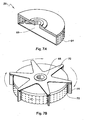
- the filter assembly (26) is preferably centrally located within the vortex chamber (24) and evenly spaced from the inner peripheral wall (22) of the tank (12). While shown as being cylindrical, other configurations may be used including stepped and conical shaped filters. As best shown in Figure 7A , the filter assembly (26) includes a porous membrane (64) which may be fabricated from a wide variety of materials include polymers, ceramics and metals. In one embodiment, the membrane is relatively thin, e.g. from 0.2 - 0.4 mm and is supported by an underlying rigid frame or porous support (not shown). A representative example is described in US2012/0010063 . The pore size (e.g. 1 to 500 micron), shape (e.g.
- V-shape, cylindrical, slotted) and uniformity of the membrane (64) may vary depending upon application.
- the membrane (64) comprises a corrosion-resistant metal (e.g. electroformed nickel screen) including uniform sized pores having sizes from 10 to 100 microns. Representative examples of such materials are described: US7632416 , US7896169 , US2011/0120959 , US 2011/0220586 and US2012/0010063 , the entire subject matter of which is incorporated herein by reference.
- the membrane (64) surrounds a filtrate chamber (66) that is in fluid communication with the filtered fluid outlet (16).
- the subject hydroclone (10) may further include a cleaning assembly (68) for removing debris from the membrane surface (64) of the filter assembly (26).
- a cleaning assembly (68) for removing debris from the membrane surface (64) of the filter assembly (26).
- a representative embodiment is illustrated in Figure 7B wherein the assembly (68) is mounted on the top surface of the filter assembly (26) and includes one or more spokes (70) extending radially outward.
- a brush (72) extends downward from the end of the spoke (70) and engages (e.g. touches or comes very near to) the surface of the membrane substrate (64). While shown as a brush (72), alternative cleaning means may be included including wipers, squeegees or scrappers. From 2 to 50 brushes, and preferably from 18 to 24 brushes are used in most embodiments.
- the cleaning assembly (68) rotates about filter assembly (26) such that the brush (72) sweeps the surface of the membrane substrate (54) and removes debris, e.g. by creating turbulence near the surface or by directly contacting the surface.
- One or more paddles (74) may be mounted to the end of at least one spoke (70) such that fluid flowing into the vortex chamber (24) rotates the cleaning assembly (68) about the filter assembly (26). Spacing paddles (74) evenly about the filter assembly adds stability to the rotating movement of the cleaning assembly (68) and may help maintain vortex fluid flow in the vortex chamber (24). While shown as extending radially outward from the surface of the membrane substrate (64), the paddles may be slanted, (e.g.
- the filter and cleaning assemblies (26, 68) may be used between the filter and cleaning assemblies (26, 68) to further facilitate rotation without impeding vortex fluid flow.
- the cleaning assembly (68) may be driven by alternative means, e.g. electronic motor, magnetic force, etc.
- the filter assembly may move relative to a fixed cleaning assembly.
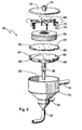
- FIG. 8-9 An alternative embodiment of the hydroclone (10) including a cylindrical tank (12) is illustrated in Figures 8-9 , incorporating the cleaning assembly (68) illustrated in Figure 7B .
- Thedepicted embodiment further includes the effluent barrier (36) illustrated in Figure 3I.
- hydroclones were tested using an aqueous feed fluid including 2000 ppm of 200 ⁇ m plastic particles having a specific gravity of 1.1.
- the hydroclones had the general configuration as shown in Figures 1-3 but further included the cleaning assembly as illustrated in Figure 7B including 20 ⁇ m pores.
- the effluent opening (38) had an inner diameter of approximately 2 inches.
- Hydroclone 1 ( ⁇ ) included no effluent barrier (36).
- Hydroclone 2 ( ⁇ ) included a flat circular effluent barrier (36) with no apertures (42') and had a diameter approximately 10 mm less than the inner diameter of the tank (12).
- Hydroclone 3 ( ⁇ ) included a flat circular effluent barrier having a diameter extending to the inner peripheral wall (22) of the tank (12) and which had scallop-shaped apertures (42') as illustrated in Figures 1B and 2 .
- Hydroclone 4 ( ⁇ ) included a cone-shaped effluent barrier having a diameter extending to the inner peripheral wall (22) of the tank (12) and including scalloped-shaped apertures (42') as illustrated in Figure 3I.
- the valve (48) was opened to remove and analyze the effluent (plastic particles).
- the results of the testing are summarized in Figure 10 wherein the Y-axis represents the cumulative percent mass removed from the feed fluid in 6 minute intervals and the X-axis represents the run time of the experiment.
- the hydroclones including the various embodiments of the subject effluent plate demonstrated significantly improved separation efficiencies. While the Examples highlight the separation of solid particles from an aqueous liquid, the subject hydroclones are also effective at separating liquid mixtures including liquids of differing densities, e.g. water and oil, or complex mixtures including liquid-liquid mixtures include various solids.
- feed fluid is subjected to a synergistic combination of multiple separation processes within a single device. Specifically, feed fluid is subject to cyclonic separation based at least partially upon density with denser material (e.g. particles, liquids) being urged toward the inner periphery of the tank. Fluid passing through the filter assembly is additionally subjected to cross-flow separation. While separation through the filter assembly may be based upon particle size, other means of separation may also be used depending upon the selection of separation media utilized in the filter assembly.
- denser material e.g. particles, liquids
- separation may also be based at least partially upon hydrophilicity or charge density.
- the effluent barrier is believed to provide yet another means of separation as the flow of denser materials or larger particles slows and the radial fluid velocity drag forces exceed any residual centrifugal forces lingering from the vortex such that these denser materials (e.g. particles, liquids) are collected within the effluent opening.
- barriers 34, 36
- the use of a cleaning assembly may still further enhance separations by clumping debris from the filter assembly and thereby add to its effective particle size or density, both of which are believe to improve separation in the effluent chamber.
Landscapes
- Chemical & Material Sciences (AREA)
- Chemical Kinetics & Catalysis (AREA)
- Cyclones (AREA)
Description
- This application claims priority from United States Provisional Application No.
61/483221 filed 6 May 2011 - The invention is generally directed toward hydroclones and cyclonic separation of fluids.
- Hydroclones are commonly used to separate suspended particles from liquids. In a typical embodiment, pressurized feed liquid (e.g. waste water) is introduced into a conically shaped chamber under conditions that create a vortex within the chamber. Generally, feed liquid is introduced near the top of a conical chamber and an effluent stream is discharged near the bottom of the chamber. Centrifugal forces associated with the vortex urge denser particles towards the periphery of the chamber. As a result, liquid located near the center of the vortex has a lower concentration of particles than that at the periphery. This "cleaner" liquid can then be withdrawn from a central region of the hydroclone. Examples of hydroclones are described in:
US3061098 ,US3529724 ,US5104520 ,US5407584 andUS5478484 . Separation efficiency can be improved by including a filter within the chamber such that a portion of the liquid moving to the center of the chamber passes through the filter. In such embodiments, cyclonic separation is combined with cross-flow filtration. Examples of such embodiments are described in:US7632416 ,US7896169 ,US2011/0120959 ,US2012/0010063 andUS 2007/0039900 . While such hybrid designs improve separation efficiency, further improvements are desired. The entire subject matter of each of the previously cited references is incorporated herein by reference. - The invention includes multiple embodiments of hydroclones and methods for performing cyclonic separations using the same. In one embodiment, the invention includes a hydroclone (10) having a tank (12) including a fluid inlet (14), a filtered fluid outlet (16), an effluent outlet (18), a process fluid outlet (20) and an inner peripheral wall (22) enclosing a plurality of vertically aligned chambers. While differing numbers of chambers may be used, in one embodiment the tank (12) includes three vertically aligned chambers including a vortex chamber (24) in fluid communication with the fluid inlet (14). A filter assembly (26) is located within the vortex chamber (24) and encloses a filtrate chamber (66). The vortex chamber (24) includes a fluid pathway (28) adapted for receiving incoming fluid and generating a vortex fluid flow about the filter assembly (26). The filtrate chamber (56) is in fluid communication with the filtered fluid outlet (16) such that fluid passing through the filter assembly (26) enters the filtrate chamber (56) and may exit the tank (12) by way of the filtered fluid outlet (16). An effluent separation chamber (30) is located below and in fluid communication with the vortex chamber (24) and is adapted for receiving unfiltered fluid from the vortex chamber (24). A process fluid chamber (32) is located below and in fluid communication with the effluent separation chamber (30) and is adapted for receiving a process fluid from the effluent separation chamber (30) wherein the process fluid chamber (32) is in fluid communication with the process fluid outlet (20) by which process fluid may exit the tank (12). A vortex flow barrier (34) is located between the vortex and effluent separation chambers (24, 30) and disrupts vortex fluid flow from the vortex chamber (24) to the effluent separation chamber (30). An effluent barrier (36) is located below the effluent separation chamber (30) and directs fluid flow from the effluent separation chamber (30) to the process fluid outlet (20), and wherein the effluent barrier (36) further comprises a centrally located effluent opening (38) in fluid communication with the effluent outlet (18) by which effluent exits the tank (12). Multiple embodiments are described.
- Various aspects of the invention may be better understood by reference to the following description taken in conjunction with the accompanying drawings wherein like numerals have been used throughout the various views to designate like parts. The depictions are illustrative and are not intended to be to scale or otherwise limit the invention.
-
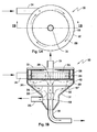
Figure 1A an elevational view showing one embodiment of the invention. -
Figure 1B is a cross-sectional view taken alonglines 1B-1B ofFig. 1A . -
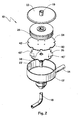
Figure 2 is an exploded perspective view of the embodiment shown inFigs. 1 A and B . -
Figures 3A-H are perspective views of various embodiments of effluent barriers. -
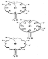
Figures 4A-C are perspective views of additional embodiments of effluent barriers. -
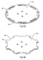
Figure 5A-B are perspective views of various embodiments of vortex barriers. -
Figure 6 is an exploded view of an effluent barrier with an effluent insert. -
Figure 7A is a perspective partially cut away view of a filter assembly. -
Figure 7B is a perspective view of the filter ofFig 7A including a cleaning assembly. -
Figure 8 is a cross-sectional view showing an alternative embodiment of the invention. -
Figure 9 is an exploded perspective view the embodiment ofFig. 8 . -
Figure 10 is a graph including test data generated according to the Examples. - The present invention generally relates to the hydroclone filtration devices and related methods of conducting cyclonic separation. For purposes of the present description, the term "hydroclone" refers to a filtration device that at least partially relies upon centrifugal forces generated by vortex fluid flow to separate constituents from a fluid mixture. Examples include the separation of solid particles from a liquid mixture and separation of mixtures including liquids of differing densities (e.g. oil and water). Specific applications include the treatment of: pulp effluent generating by paper mills, process water generated by oil and gas recovery, bilge water and municipal and industrial waste water.
- One embodiment of the invention is illustrated in
Figures 1-3 including a hydroclone generally shown at 10 including a tank (12) having a removable lid (13), a fluid inlet (14), a filtered fluid outlet (16), an effluent outlet (18), a process fluid outlet (20) and an inner peripheral wall (22) enclosing a plurality of vertically aligned chambers (24, 30, 32). While depicted as including three vertically aligned chambers, additional chambers may also be included. Similarly, additional fluid inlets and outlets may also be included. While shown as having a cylindrical upper section and a frustro-conical base, the tank (12) may have other configurations including an entirely cylindrical shape as will be described in connection withFigures 8 and9 . - The tank (12) includes a vortex chamber (24) in fluid communication with the fluid inlet (14). A filter assembly (26) is centrally located within the vortex chamber (24) and encloses a filtrate chamber (66), (as best shown in
Figure 7A ). The filtrate chamber (56) is in fluid communication with the filtered fluid outlet (16). An effluent separation chamber (30) is located below and is in fluid communication with the vortex chamber (24). The effluent separation chamber (30) is adapted for receiving unfiltered fluid from the vortex chamber (24). A process fluid chamber (32) is in turn located below and is in fluid communication with the effluent separation chamber (30). The process fluid chamber (32) is adapted for receiving a process fluid from the effluent separation chamber (30) and is in fluid communication with the process fluid outlet (20) by which process fluid may exit the tank (12). - A vortex flow barrier (34) is located between the vortex and effluent separation chambers (24, 30) and directs fluid flow between the vortex and effluent separation (24, 30) chambers to locations adjacent to the inner peripheral wall (22) of the tank (12). The vortex flow barrier (34) may be designed to maintain vortex fluid flow in the effluent separation chamber (24) and disrupt vortex fluid flow (28) as fluid flows from the vortex chamber (24) into the effluent separation chamber (30). More specifically, the vortex flow barrier (34) includes an outer periphery (40) extending to locations adjacent to or in contact with the inner peripheral wall (22) of the tank (12) and may further include a plurality of apertures (42) located near the periphery (40) and extending therethrough. In the illustrated embodiment, the apertures (42) are scalloped-shaped but alternative shapes may also be used (as best shown in
Figure 6 ). - An effluent barrier (36) is located below the effluent separation chamber (30) and is adapted to direct fluid flow from the effluent separation chamber (30) to the process fluid outlet (20). The effluent barrier (36) includes an outer periphery (40') extending to locations adjacent to or in contact with the inner peripheral wall (22) of the tank (12) and may further include a plurality of apertures (42') located near the periphery (40') and extending therethrough. In the illustrated embodiment, the apertures (42') are scalloped-shaped but alternative shapes may also be used (as best shown in
Figure 4 ). In a preferred embodiment, the apertures (42) of the vortex flow barrier (34) are vertically off-set from the apertures (42') of the effluent barrier (36), as shown by dotted arrows inFigure 2 . The effluent barrier (36) also includes a centrally located effluent opening (38) in fluid communication with the effluent outlet (18) by which effluent may exit the tank (12). - In operation, pressurized feed fluid (e.g. preferably from 4 to 120 psi) enters the tank (12) via the fluid inlet (14) and follows along fluid pathway (28) which generates a vortex about the filter assembly (26). Centrifugal forces urge denser materials toward the inner peripheral wall (22) of the tank (12) while less dense liquid flows radially inward toward the filter assembly (26). A portion of this liquid flows through the filter assembly (26) into a filtrate chamber (66) and may subsequently exit the tank (12) as "filtrate" by way of the filtered fluid outlet (16). The remaining "non-filtrate" flows downward from the vortex chamber (24) to the effluent separation chamber (30). The vortex flow barrier (34) directs the majority (e.g. preferably at least 75% and in some embodiments at least 90%) of such downward flow to locations along or adjacent to an inner peripheral wall (22) of the tank (12). This arrangement is believed to help maintain vortex flow within the vortex chamber (24) while disrupting the vortex flow as fluid enters the effluent separation chamber (30). Fluid flow slows in the effluent separation chamber (30) and denser materials (e.g. particles) preferentially settle toward the center of the effluent barrier (34) and enter into the effluent opening (38) and may then exit the tank by way of effluent outlet (18). The effluent outlet (18) may optionally include a valve (48) (e.g. one-way check value) to selectively control removal of effluent from the tank (12). The remaining liquid (hereinafter referred to as "process fluid") in the effluent separation chamber (30) flows downward into the process fluid chamber (32). The effluent barrier (36) directs a majority (e.g. preferably at least 75% and in some embodiments at least 90%) of fluid flow between the effluent separation vortex and process fluid chambers (34, 36) to locations along or adjacent to an inner peripheral wall (22) of the tank (12), i.e. through apertures (42'). In most applications, process fluid represents a mid-grade product that may be re-used, disposed of or recycled back to the fluid inlet (14) for further treatment. "Filtrate" typically represents a high grade product that may be re-used or disposed of. "Effluent" represents a low grade product that may be further treated or disposed of. However, it should be appreciated that in some applications, effluent may represent a valuable product.
- The feed fluid inlet pressure and spacing between the outer periphery of the filter assembly (26) and the inner peripheral wall (22) of the tank (12) can be optimized to create and maintain a vortex fluid flow within the vortex chamber (24). In order to further facilitate the creation and maintenance of vortex fluid flow, the fluid inlet (14) preferably directs incoming feed fluid on a tangential path about the vortex chamber, as indicated by dotted arrows in
Figure 1A . - Ideal configurations of the vortex flow barrier (34) and effluent barrier (36) can be determined based upon the operating conditions of the hydroclone and composition of the feed fluid. A variety of embodiments of the effluent barrier (36) are illustrated in
Figures 3A-I . For example, rather than utilizing a flat plate-like configuration as illustrated inFigures 1-3 (e.g. circular flat surface having an outer periphery 40), the effluent barrier (36) may include alternative configurations wherein a central region, (i.e. directly adjacent the effluent opening (38)) is located at a lower or higher position relative to the periphery. Representative examples are illustrated inFigures 3A-D , e.g.Figure 3A illustrates a bowl-like configuration including an upward facing concave surface (44). While shown as including a constant degree of curvature, the degree of curvature may vary across the surface (44).Figure 3B illustrates a similar design including an upward facing convex surface (46).Figure 3C illustrates an embodiment including a plate-like configuration including a raised wall (48) about the effluent opening (38).Figure 3D illustrates an embodiment including shared features from bothFigures 3A and 3C , i.e. a concave surface (44') and a raised wall (48') about the effluent opening (38).Figures 3E-F illustrate plate-like configurations which may include one or more radially extending ridges (50) and grooves (52), whereasFigure 3G illustrates the use of a spiral shaped groove (52). While not shown, ridges and grooves (whether radial or spiral), may also be combined together or used separately with the configurations illustrated inFigures 3A-D . Each of the illustrated embodiments is designed to facilitate collection of denser materials or particles based upon the specific feed flow conditions and composition.Figure 3H shows a preferred embodiment including a conical shape including a conical angle of about 80° (i.e. 80° from a vertical axis, 10° from a horizontal axis). Preferred conical angles are from 45°to 85°. While not illustrated, many of these illustrated features are also applicable to the vortex flow barrier (34), e.g. convex and concave upward facing surfaces. - While in one embodiment the effluent barrier (36) includes scalloped-shaped apertures (42'), alternatively shaped apertures may also be used including radial slots, angled slots and triangular openings located about the outer periphery (40'), as illustrated in
Figures 4A-C . Similarly, alternatively shaped apertures (42) may be used with respect to the vortex flow barrier (34), as illustrated inFigures 5A-B . The shape and size of the aperture (42, 42') may be designed to control the flow of fluid downward through the chambers (24, 30, 32) of the tank (12), with flow being preferentially directed to the inner peripheral wall (22) of the tank (12). With that said, a minority (e.g. less than 50% and more preferably less than 75% and still more preferably less than 90%) of the downward flow (i.e. non-effluent fluid with respect to the effluent barrier (36)) may occur at alternative locations including the center location of one or both barriers (42, 36). In yet other non-illustrated embodiment, one or both of the vortex flow barrier (34) and effluent barrier (36) may include outer peripheries that do not contact the inner peripheral wall (22) of the tank (12) and include no apertures. -
Figure 6 shows an optional effluent insert (54) adapted to fit within the effluent opening (38) of the effluent barrier (36). While shown in combination with a flat-plate like configuration barrier (36), the insert (54) may also be used in combination with the other embodiments as illustrated inFigures 3A-H and4A-C . The effluent insert (54) includes a concentric tube configuration including an end (56) adapted to snugly fit into the effluent opening (38) and extend upwardly therefrom. An inner tube (58) extends along at least a portion of the length of the insert (54) and provides a pathway for fluid to flow upward. An outer tube (60) include one or more apertures (62), e.g. slots, located at the intersection of the upper surface (44) of the effluent barrier (36) and the insert (54). The insert (54) is designed to slow fluid flow and facilitate the flow of denser materials into the effluent opening (38) while permitting less dense fluids to flow upward out of the insert (54). While shown as a separate component part, the insert (54) may form an integral part of the effluent barrier (36). - As shown in
Figures 1-3 , the filter assembly (26) is preferably centrally located within the vortex chamber (24) and evenly spaced from the inner peripheral wall (22) of the tank (12). While shown as being cylindrical, other configurations may be used including stepped and conical shaped filters. As best shown inFigure 7A , the filter assembly (26) includes a porous membrane (64) which may be fabricated from a wide variety of materials include polymers, ceramics and metals. In one embodiment, the membrane is relatively thin, e.g. from 0.2 - 0.4 mm and is supported by an underlying rigid frame or porous support (not shown). A representative example is described inUS2012/0010063 . The pore size (e.g. 1 to 500 micron), shape (e.g. V-shape, cylindrical, slotted) and uniformity of the membrane (64) may vary depending upon application. In many preferred embodiments, the membrane (64) comprises a corrosion-resistant metal (e.g. electroformed nickel screen) including uniform sized pores having sizes from 10 to 100 microns. Representative examples of such materials are described:US7632416 ,US7896169 ,US2011/0120959 ,US 2011/0220586 andUS2012/0010063 , the entire subject matter of which is incorporated herein by reference. The membrane (64) surrounds a filtrate chamber (66) that is in fluid communication with the filtered fluid outlet (16). - The subject hydroclone (10) may further include a cleaning assembly (68) for removing debris from the membrane surface (64) of the filter assembly (26). A representative embodiment is illustrated in
Figure 7B wherein the assembly (68) is mounted on the top surface of the filter assembly (26) and includes one or more spokes (70) extending radially outward. A brush (72) extends downward from the end of the spoke (70) and engages (e.g. touches or comes very near to) the surface of the membrane substrate (64). While shown as a brush (72), alternative cleaning means may be included including wipers, squeegees or scrappers. From 2 to 50 brushes, and preferably from 18 to 24 brushes are used in most embodiments. As represented by curved arrows, the cleaning assembly (68) rotates about filter assembly (26) such that the brush (72) sweeps the surface of the membrane substrate (54) and removes debris, e.g. by creating turbulence near the surface or by directly contacting the surface. One or more paddles (74) may be mounted to the end of at least one spoke (70) such that fluid flowing into the vortex chamber (24) rotates the cleaning assembly (68) about the filter assembly (26). Spacing paddles (74) evenly about the filter assembly adds stability to the rotating movement of the cleaning assembly (68) and may help maintain vortex fluid flow in the vortex chamber (24). While shown as extending radially outward from the surface of the membrane substrate (64), the paddles may be slanted, (e.g. from -5° to -30° or 5° to 30° from the radial axis) to increase rotational velocity. Bearings may be used between the filter and cleaning assemblies (26, 68) to further facilitate rotation without impeding vortex fluid flow. In alternative embodiments not shown, the cleaning assembly (68) may be driven by alternative means, e.g. electronic motor, magnetic force, etc. In yet another embodiment, the filter assembly may move relative to a fixed cleaning assembly. - An alternative embodiment of the hydroclone (10) including a cylindrical tank (12) is illustrated in
Figures 8-9 , incorporating the cleaning assembly (68) illustrated inFigure 7B . Thedepicted embodiment further includes the effluent barrier (36) illustrated in Figure 3I. - By way of further illustration, four different hydroclones were tested using an aqueous feed fluid including 2000 ppm of 200 µm plastic particles having a specific gravity of 1.1. The hydroclones had the general configuration as shown in
Figures 1-3 but further included the cleaning assembly as illustrated inFigure 7B including 20 µm pores. The effluent opening (38) had an inner diameter of approximately 2 inches. - Hydroclone 1 (◆) included no effluent barrier (36).
- Hydroclone 2 (■) included a flat circular effluent barrier (36) with no apertures (42') and had a diameter approximately 10 mm less than the inner diameter of the tank (12).
- Hydroclone 3 (●) included a flat circular effluent barrier having a diameter extending to the inner peripheral wall (22) of the tank (12) and which had scallop-shaped apertures (42') as illustrated in
Figures 1B and2 . - Hydroclone 4 (▲) included a cone-shaped effluent barrier having a diameter extending to the inner peripheral wall (22) of the tank (12) and including scalloped-shaped apertures (42') as illustrated in Figure 3I.
- All Hydroclones were tested under the same conditions. More specifically, 100 gallons (378.5 1) of feed fluid was pumped into the feed inlet (14) of the hydroclone at a rate of 30 gpm (112.6 l/minute) from a holding tank. Filtrate was removed from the filtered fluid inlet (16) at a rate of 30 gpm (112.6 l/minute) and was returned to the holding tank. The pressure differential across the filter substrate (54) was approximately 0.5 psi (3.5 KPa). Process fluid from the process fluid outlet (20) was re-circulated and re-introduced into the fluid feed inlet (14) at a rate of 120 gpm (454.2 l/min). Every six minutes, the valve (48) was opened to remove and analyze the effluent (plastic particles). The results of the testing are summarized in
Figure 10 wherein the Y-axis represents the cumulative percent mass removed from the feed fluid in 6 minute intervals and the X-axis represents the run time of the experiment. As is clear from these experimental results, the hydroclones including the various embodiments of the subject effluent plate demonstrated significantly improved separation efficiencies. While the Examples highlight the separation of solid particles from an aqueous liquid, the subject hydroclones are also effective at separating liquid mixtures including liquids of differing densities, e.g. water and oil, or complex mixtures including liquid-liquid mixtures include various solids. - The subject hydroclones provide unexpectedly superior separation efficiencies as compared with previous designs. These efficiencies allow the hydroclone to be used a broader range of applications; particular in embodiments where process fluid is recycled and optionally blended with make-up feed fluid. Broadly stated, feed fluid is subjected to a synergistic combination of multiple separation processes within a single device. Specifically, feed fluid is subject to cyclonic separation based at least partially upon density with denser material (e.g. particles, liquids) being urged toward the inner periphery of the tank. Fluid passing through the filter assembly is additionally subjected to cross-flow separation. While separation through the filter assembly may be based upon particle size, other means of separation may also be used depending upon the selection of separation media utilized in the filter assembly. For example, separation may also be based at least partially upon hydrophilicity or charge density. While not wishing to be bound by theory, the effluent barrier is believed to provide yet another means of separation as the flow of denser materials or larger particles slows and the radial fluid velocity drag forces exceed any residual centrifugal forces lingering from the vortex such that these denser materials (e.g. particles, liquids) are collected within the effluent opening. These synergistic separations are further enhanced by the use of barriers (34, 36) that limit fluid flow in constrained areas about the inner peripheral wall of the hydroclone tank. The use of a cleaning assembly may still further enhance separations by clumping debris from the filter assembly and thereby add to its effective particle size or density, both of which are believe to improve separation in the effluent chamber.
Claims (8)
- A hydroclone (10) comprising a tank (12) including a fluid inlet (14), a filtered fluid outlet (16), an effluent outlet (18), a process fluid outlet (20) and an inner peripheral wall (22) enclosing a plurality of vertically aligned chambers comprising:a vortex chamber (24) in fluid communication with the fluid inlet (14), a filter assembly (26) located within the vortex chamber (24) and enclosing a filtrate chamber (56), a fluid pathway (28) adapted for receiving incoming fluid and generating a vortex fluid flow about the filter assembly (26), wherein the filtrate chamber (66) is in fluid communication with the filtered fluid outlet (16) such that fluid passing through the filter assembly (26) enters the filtrate chamber (56) and exits the tank (12) by way of the filtered fluid outlet (16),an effluent separation chamber (30) located below and in fluid communication with the vortex chamber (24) which is adapted for receiving unfiltered fluid from the vortex chamber (24), a vortex flow barrier (34) located between the vortex and effluent separation chambers (24, 30) which disrupts vortex fluid flow (28) as fluid flows from the vortex chamber (24) to the effluent separation chamber (30)characterized in that a process fluid chamber (32) located below and in fluid communication with the effluent separation chamber (30) which is adapted for receiving a process fluid from the effluent separation chamber (30) and wherein the process fluid chamber (32) is in fluid communication with the process fluid outlet (20) by which process fluid exits the tank (12),and in thatan effluent barrier (36) located below the effluent separation chamber (30) which directs fluid flow from the effluent separation chamber (30) to the process fluid outlet (20), and wherein the effluent barrier (36) further comprises a centrally located effluent opening (38) in fluid communication with the effluent outlet (18) by which effluent exits the tank (12).
- The hydroclone (10) of claim 1 wherein the vortex flow barrier (34) directs a majority of fluid flow between the vortex and effluent separation (24, 30) chambers to locations adjacent to the inner peripheral wall (22) of the tank (12).
- The hydroclone (10) of claim 1 wherein the effluent barrier (36) limits a majority of fluid flow between the effluent separation and process fluid chambers (34, 36) to locations adjacent to the inner peripheral wall (22) of the tank (12).
- The hydroclone (10) of claim 1 wherein the effluent barrier (36) further comprises an outer periphery (40') extending to locations adjacent to the inner peripheral wall (22) of the tank (12), and further comprises a plurality of apertures (42') extending therethrough.
- The hydroclone (10) of claim 1 wherein at least one of the vortex flow barrier (34) and effluent barrier (36) comprise a plate-shaped configuration.
- The hydroclone (10) of claim 1 wherein the vortex flow barrier (34) and effluent barrier (36) both comprise configurations including an outer periphery (40, 40') extending to locations adjacent to the inner peripheral wall (22) of the tank (12), and further comprise a plurality of apertures (42, 42') extending through the barriers (34, 36) at locations adjacent to their outer periphery (40, 40') that permit fluid flow therethrough.
- The hydroclone (10) of claim 6 wherein the apertures (42) of the vortex flow barrier (34) are vertically off-set from the apertures (42') of the effluent barrier (36).
- The hydroclone (10) of claim 1 wherein the effluent barrier (36) comprises a central region that is lower or higher than the outer periphery (40).
Applications Claiming Priority (2)
| Application Number | Priority Date | Filing Date | Title |
|---|---|---|---|
| US201161483221P | 2011-05-06 | 2011-05-06 | |
| PCT/US2012/035966 WO2012154448A1 (en) | 2011-05-06 | 2012-05-01 | Multi-chambered hydroclone |
Publications (3)
| Publication Number | Publication Date |
|---|---|
| EP2646129A1 EP2646129A1 (en) | 2013-10-09 |
| EP2646129A4 EP2646129A4 (en) | 2014-07-02 |
| EP2646129B1 true EP2646129B1 (en) | 2015-07-15 |
Family
ID=47139519
Family Applications (1)
| Application Number | Title | Priority Date | Filing Date |
|---|---|---|---|
| EP12782820.0A Active EP2646129B1 (en) | 2011-05-06 | 2012-05-01 | Multi-chambered hydroclone |
Country Status (5)
| Country | Link |
|---|---|
| US (1) | US8663472B1 (en) |
| EP (1) | EP2646129B1 (en) |
| CN (1) | CN103347580B (en) |
| CA (1) | CA2828922C (en) |
| WO (1) | WO2012154448A1 (en) |
Families Citing this family (26)
| Publication number | Priority date | Publication date | Assignee | Title |
|---|---|---|---|---|
| US9186175B2 (en) | 2004-10-28 | 2015-11-17 | Nico Corporation | Surgical access assembly and method of using same |
| US9387010B2 (en) * | 2004-10-28 | 2016-07-12 | Nico Corporation | Surgical access assembly and method of using same |
| US9161820B2 (en) | 2004-10-28 | 2015-10-20 | Nico Corporation | Surgical access assembly and method of using same |
| MX2008002188A (en) | 2005-08-18 | 2008-04-10 | Clean Filtration Technologies Inc | Hydroclone based fluid filtration system. |
| US9199247B2 (en) * | 2007-05-29 | 2015-12-01 | Invitrogen Dynal As | Magnetic separation rack |
| US8960450B2 (en) | 2010-12-08 | 2015-02-24 | Dow Global Technologies Llc | Apparatus and method for implementing hydroclone based fluid filtration systems with extensible isolated filter stages |
| KR102141785B1 (en) | 2012-05-17 | 2020-08-06 | 다우 글로벌 테크놀로지스 엘엘씨 | Hydroclone with inlet flow shield |
| US9186604B1 (en) | 2012-05-31 | 2015-11-17 | Dow Global Technologies Llc | Hydroclone with vortex flow barrier |
| CA2872329A1 (en) | 2012-06-01 | 2013-12-05 | Dow Global Technologies Llc | Cross-flow filtration system including particulate settling zone |
| WO2014066036A2 (en) * | 2012-10-26 | 2014-05-01 | Dow Global Technologies Llc | Hydroclone |
| US9393532B2 (en) | 2013-02-27 | 2016-07-19 | Dow Global Technologies Llc | Swept membrane emulsification |
| WO2015084901A1 (en) | 2013-12-05 | 2015-06-11 | Dow Global Technologies Llc | Hydroclone with improved cleaning assembly |
| FR3016805A1 (en) * | 2014-01-29 | 2015-07-31 | Piscines Desjoyaux Sa | DEVICE FOR FILTRATION OF A LIQUID BY CYCLONIC EFFECT |
| WO2015138015A1 (en) | 2014-03-14 | 2015-09-17 | Dow Global Technologies Llc | Cross-flow filter assembly with improved cleaning assembly |
| CN106999814B (en) | 2014-12-18 | 2020-01-24 | 陶氏环球技术有限责任公司 | Cylindrical filter screen with tensioning mechanism |
| WO2019198227A1 (en) * | 2018-04-13 | 2019-10-17 | 三菱電機株式会社 | Foreign matter trapping device and water circulation circuit comprising foreign matter trapping device |
| CN108479216B (en) * | 2018-05-31 | 2020-04-21 | 贵州环科环境工程有限公司 | Stepping air suction ash removal dust remover |
| EP3829739A1 (en) | 2018-07-27 | 2021-06-09 | DDP Specialty Electronic Materials US, LLC | Filter screen |
| CN109603294A (en) * | 2018-12-29 | 2019-04-12 | 安徽普氏生态环境工程有限公司 | A kind of equipment for separating liquid from solid for wastewater treatment |
| CN109569041A (en) * | 2018-12-29 | 2019-04-05 | 安徽普氏生态环境工程有限公司 | A kind of vertical hydrodynamic force solid-liquid separating equipment |
| CN109603223A (en) * | 2018-12-29 | 2019-04-12 | 安徽普氏生态环境工程有限公司 | A solid-liquid separation equipment utilizing inertial separation |
| CN109569040A (en) * | 2018-12-29 | 2019-04-05 | 安徽普氏生态环境工程有限公司 | A kind of rotary and centrifugal type Chinese medicine equipment for separating liquid from solid |
| CN109603295A (en) * | 2018-12-29 | 2019-04-12 | 安徽普氏生态环境工程有限公司 | A kind of inertial solid-liquid separation equipment using water flow as power |
| CN109603296A (en) * | 2018-12-29 | 2019-04-12 | 安徽普氏生态环境工程有限公司 | A kind of solid-liquid separation equipment using inertia mixed flow |
| NL2023332B1 (en) * | 2019-06-17 | 2021-01-25 | Mst Nl B V | Filter device for removing particles from a fluid |
| SE543689C2 (en) * | 2019-10-04 | 2021-06-08 | Mimbly Ab | Improved filter assembly with self-cleaning |
Family Cites Families (81)
| Publication number | Priority date | Publication date | Assignee | Title |
|---|---|---|---|---|
| US2706045A (en) | 1955-04-12 | Liquid separation | ||
| US431448A (en) | 1890-07-01 | Filter | ||
| US3285422A (en) | 1966-11-15 | Sand trap | ||
| US1107485A (en) | 1909-09-01 | 1914-08-18 | Sf Bowser & Co Inc | Separator. |
| US1919653A (en) | 1931-11-27 | 1933-07-25 | Raymond A Hill | Hydraulic sand extractor |
| US2788087A (en) | 1955-04-07 | 1957-04-09 | Research Corp | Gas cleaning apparatus |
| US2917173A (en) | 1957-08-21 | 1959-12-15 | Rakowsky Victor | Centrifugal method and apparatus for separating solids |
| US3061098A (en) | 1960-07-18 | 1962-10-30 | Beloit Iron Works | Centrifugal classifier and stock cleaner |
| US3219186A (en) | 1962-10-30 | 1965-11-23 | Victor Rakowsky | Whirlpool apparatus |
| US3529724A (en) | 1969-09-10 | 1970-09-22 | Univ Oklahoma State | Hydrocyclone filter |
| US3822533A (en) | 1972-03-04 | 1974-07-09 | Nederlandse Gasunie Nv | Device for removing impurities from gases |
| US3893914A (en) | 1973-04-05 | 1975-07-08 | Roy A Bobo | Cyclone centrifuge apparatus |
| CA1038353A (en) | 1976-08-31 | 1978-09-12 | Canarco Inc. | Centrifugal separator |
| SE410276B (en) | 1976-10-20 | 1979-10-08 | Sala International Ab | DYNAMIC SUSPENSION ENRICHMENT EQUIPMENT |
| US4146468A (en) | 1977-05-24 | 1979-03-27 | Wilson George E | Apparatus and method of classifying solids and liquids |
| US4120783A (en) | 1977-07-05 | 1978-10-17 | Baummer George P | Apparatus and process for ordinary and submarine mineral beneficiation |
| US4219409A (en) | 1977-12-14 | 1980-08-26 | Liller Delbert I | Inlet line deflector and equalizer means for a classifying cyclone used for washing and method of washing using deflectors and equalizers |
| US4178258A (en) | 1978-05-18 | 1979-12-11 | Edwin Cooper, Inc. | Lubricating oil composition |
| US4298465A (en) | 1979-06-07 | 1981-11-03 | Racor Industries, Inc. | Fuel filter and water separator apparatus |
| US4414112A (en) | 1982-01-29 | 1983-11-08 | Recovery Technology Associates | Oil/water separator |
| GB2158741B (en) | 1984-05-14 | 1988-08-17 | Hydro Int Ltd | Separation of components of a fluid mixture |
| US4575406A (en) | 1984-07-23 | 1986-03-11 | Polaroid Corporation | Microporous filter |
| DE3437037A1 (en) | 1984-10-09 | 1986-04-10 | Krupp Polysius Ag, 4720 Beckum | CYCLONE ARRANGEMENT |
| US4651540A (en) | 1986-03-21 | 1987-03-24 | Tecumseh Products Company | Suction accumulator including an entrance baffle |
| US4698156A (en) | 1986-04-03 | 1987-10-06 | Microspun Technologies Inc. | Rotating filter apparatus for separating fine particles of solids from a liquid |
| US5188238A (en) * | 1989-06-21 | 1993-02-23 | Hydro International Limited | Separator for separating solids components of liquid mixtures and method of using the same |
| GB2241904B (en) | 1990-03-16 | 1993-12-01 | Hydro Int Ltd | Separator |
| US5104520A (en) | 1990-06-25 | 1992-04-14 | The United States Of America As Represented By The United States Department Of Energy | Apparatus and method for separating constituents |
| NZ239581A (en) | 1990-09-13 | 1993-03-26 | Mitsubishi Heavy Ind Ltd | Gas-liquid separator with tangential inflow nozzle to cylindrical body with central discharge pipe |
| US5158678A (en) | 1990-09-28 | 1992-10-27 | Broussard Paul C Sr | Water clarification method and apparatus |
| GB9116020D0 (en) | 1991-07-25 | 1991-09-11 | Serck Baker Ltd | Separator |
| US5227061A (en) | 1992-01-13 | 1993-07-13 | Bedsole Robert D | Fuel/contaminant separator |
| EP0566792A1 (en) | 1992-04-24 | 1993-10-27 | Hydro International Limited | Separator |
| FR2697447B1 (en) | 1992-11-05 | 1995-01-13 | Inst Francais Du Petrole | Device and method for performing phase separation by filtration and centrifugation. |
| NO176507C (en) | 1992-12-01 | 1995-04-19 | Sinvent Sintef Gruppen | Rotor for classifier |
| US5277705A (en) | 1992-12-30 | 1994-01-11 | Iowa State University Research Foundation, Inc. | Powder collection apparatus/method |
| CN2150923Y (en) * | 1993-04-03 | 1993-12-29 | 煤炭科学研究总院唐山分院 | Water cyclone |
| DE4420730A1 (en) | 1994-06-15 | 1995-12-21 | Henkel Kgaa | Process for the deodorization and stabilization of biotechnologically obtained valuable substances and their aqueous preparations |
| US6117340A (en) | 1995-05-01 | 2000-09-12 | Carstens; Christopher | Pool vacuum prefiltering method, utilizing centrifugal force |
| GB2309182A (en) | 1996-01-19 | 1997-07-23 | Grant Budge | Dry solids/solids separation process |
| US5879545A (en) | 1997-05-05 | 1999-03-09 | Antoun; Gregory S. | Cyclonic filter assembly |
| US5972215A (en) | 1997-09-03 | 1999-10-26 | Kammel; Refaat A. | Continuous particle separation and removal cleaning system |
| GB9817071D0 (en) | 1997-11-04 | 1998-10-07 | Bhr Group Ltd | Cyclone separator |
| FR2771305B1 (en) | 1997-11-26 | 2000-02-11 | Dit Zhitariouk Nikol Jitariouk | APPARATUS, SYSTEM AND METHOD FOR SEPARATING LIQUIDS |
| US6210457B1 (en) | 1998-04-08 | 2001-04-03 | Lee Valley Tools Ltd. | Transparent lid for auxiliary dust removal receptacle |
| US6238579B1 (en) | 1998-05-12 | 2001-05-29 | Mba Polymers, Inc. | Device for separating solid particles in a fluid stream |
| US6110242A (en) | 1998-10-13 | 2000-08-29 | Blower Application Company, Inc. | Apparatus for separating solids from a gas |
| US6896720B1 (en) | 1999-02-18 | 2005-05-24 | Adrian Christopher Arnold | Cleaning apparatus |
| DE19914674C1 (en) | 1999-03-31 | 2000-12-28 | Fraunhofer Ges Forschung | Apparatus for dynamic filtration of fluid-solid mixture particularly suspensions has filter chamber |
| FR2791904B1 (en) | 1999-04-07 | 2002-05-17 | Rime Sa | DEVICE FOR RETENTION OF IMPURITIES CONTAINED IN SUSPENSION IN A FLUID |
| US6251296B1 (en) | 1999-07-27 | 2001-06-26 | G.B.D. Corp. | Apparatus and method for separating particles from a cyclonic fluid flow |
| GB0005898D0 (en) | 2000-03-10 | 2000-05-03 | Templeton Stephen J | Method and apparatus for introducing a moving liquid into a larger mass of moving liquid |
| AU2001287020A1 (en) | 2000-09-01 | 2002-03-13 | Shell International Research Maatschappij B.V. | Cyclone entrance nozzle |
| EP1295647A1 (en) | 2001-09-24 | 2003-03-26 | The Technology Partnership Public Limited Company | Nozzles in perforate membranes and their manufacture |
| US7166230B2 (en) | 2002-01-09 | 2007-01-23 | Halvor Nilsen | Apparatus and method for separating and filtering particles and organisms from flowing liquids |
| US6739456B2 (en) | 2002-06-03 | 2004-05-25 | University Of Florida Research Foundation, Inc. | Apparatus and methods for separating particles |
| ATE266478T1 (en) | 2002-07-24 | 2004-05-15 | Cattani Spa | CYCLONE SEPARATOR FOR VARIABLE FLOW RATES |
| AU2003900226A0 (en) | 2003-01-21 | 2003-02-06 | Sarah Elizabeth Chenery Lobban | A filter system |
| US7025890B2 (en) | 2003-04-24 | 2006-04-11 | Griswold Controls | Dual stage centrifugal liquid-solids separator |
| KR100511328B1 (en) | 2003-06-05 | 2005-08-31 | 엘지전자 주식회사 | Dustbox structure for cyclone cieaner |
| DE102004041768B4 (en) * | 2003-09-08 | 2013-04-11 | Robert Bosch Gmbh | cyclone |
| US7727386B2 (en) | 2003-11-21 | 2010-06-01 | Dibella Alberto | Voraxial filtration system with self-cleaning auxiliary filtration apparatus |
| US7351269B2 (en) | 2003-12-22 | 2008-04-01 | Lau Kwok Yau | Self cleaning filter and vacuum incorporating same |
| WO2006011921A2 (en) | 2004-03-10 | 2006-02-02 | Gordon Construction, Inc. | Method and system for filtering sediment-bearing fluids |
| DE102004039182B4 (en) * | 2004-08-12 | 2010-07-15 | Hilarius Drzisga | Process for separating pollutant particles from industrial gases and apparatus for carrying out the process |
| GB2423264A (en) | 2005-02-17 | 2006-08-23 | Lorne Entwistle | A sludge separator |
| MX2008002188A (en) * | 2005-08-18 | 2008-04-10 | Clean Filtration Technologies Inc | Hydroclone based fluid filtration system. |
| NL1030081C2 (en) | 2005-09-30 | 2007-04-02 | Stork Veco Bv | Sieve material from metal and method for its manufacture. |
| CN2897388Y (en) * | 2006-03-25 | 2007-05-09 | 合肥工业大学 | Cross-flow vortex solid-liquid separation device |
| US7785479B1 (en) | 2007-05-01 | 2010-08-31 | Michael Hays Hosford | Apparatus and method of separating |
| KR100899416B1 (en) | 2007-05-17 | 2009-05-26 | 신강하이텍(주) | Non-point source removal device using swirl flow screen |
| DE102007039182A1 (en) | 2007-08-20 | 2009-02-26 | Lucas Automotive Gmbh | Brake force producer for motor vehicle brake assembly, has control valve with control valve housing and coupled to movable wall, and actuating piston coupled with force input element for actuating control valve after bypassing free path |
| CN201140115Y (en) * | 2007-12-12 | 2008-10-29 | 武汉大学 | Rotating screen hydrocyclone separator |
| KR101462945B1 (en) | 2008-01-02 | 2014-11-20 | 삼성전자주식회사 | Vacuum cleaner dust collector |
| WO2010019526A1 (en) | 2008-08-14 | 2010-02-18 | Brent Lee | Dynamic filtration device using centrifugal force |
| US7998251B2 (en) | 2008-10-03 | 2011-08-16 | B/E Aerospace, Inc. | Vortex waste separator apparatus |
| US8389807B2 (en) | 2009-12-30 | 2013-03-05 | Pioneer Hi-Bred International, Inc. | Method for increasing efficiency of germplasm screening in plant transformation |
| WO2011112872A2 (en) | 2010-03-12 | 2011-09-15 | Levitt David J | Fluid filtration and particle concentration device and methods |
| US8882999B2 (en) * | 2010-06-17 | 2014-11-11 | Dow Global Technologies Llc | Cleaning assembly for use in fluid filtration systems |
| US8960450B2 (en) | 2010-12-08 | 2015-02-24 | Dow Global Technologies Llc | Apparatus and method for implementing hydroclone based fluid filtration systems with extensible isolated filter stages |
| TWM414266U (en) * | 2011-03-28 | 2011-10-21 | Univ Tamkang | Cyclone water separator with filtration function |
-
2012
- 2012-05-01 EP EP12782820.0A patent/EP2646129B1/en active Active
- 2012-05-01 CN CN201280007451.7A patent/CN103347580B/en active Active
- 2012-05-01 WO PCT/US2012/035966 patent/WO2012154448A1/en not_active Ceased
- 2012-05-01 CA CA2828922A patent/CA2828922C/en active Active
- 2012-05-01 US US13/581,578 patent/US8663472B1/en active Active
Also Published As
| Publication number | Publication date |
|---|---|
| US20140042083A1 (en) | 2014-02-13 |
| WO2012154448A1 (en) | 2012-11-15 |
| US8663472B1 (en) | 2014-03-04 |
| CA2828922A1 (en) | 2012-11-15 |
| EP2646129A4 (en) | 2014-07-02 |
| EP2646129A1 (en) | 2013-10-09 |
| CN103347580B (en) | 2015-05-20 |
| CN103347580A (en) | 2013-10-09 |
| CA2828922C (en) | 2019-03-12 |
Similar Documents
| Publication | Publication Date | Title |
|---|---|---|
| US8663472B1 (en) | Multi-chambered hydroclone | |
| EP2849864B1 (en) | Hydroclone with inlet flow shield | |
| US9186604B1 (en) | Hydroclone with vortex flow barrier | |
| US9101859B2 (en) | Cross-flow filtration system including particulate settling zone | |
| US9192946B2 (en) | Hydroclone | |
| US9527091B2 (en) | Hydroclone with improved cleaning assembly | |
| US9782698B2 (en) | Liquid refinement | |
| US20180028941A1 (en) | Liquid refinement |
Legal Events
| Date | Code | Title | Description |
|---|---|---|---|
| PUAI | Public reference made under article 153(3) epc to a published international application that has entered the european phase |
Free format text: ORIGINAL CODE: 0009012 |
|
| 17P | Request for examination filed |
Effective date: 20130613 |
|
| AK | Designated contracting states |
Kind code of ref document: A1 Designated state(s): AL AT BE BG CH CY CZ DE DK EE ES FI FR GB GR HR HU IE IS IT LI LT LU LV MC MK MT NL NO PL PT RO RS SE SI SK SM TR |
|
| A4 | Supplementary search report drawn up and despatched |
Effective date: 20140530 |
|
| RIC1 | Information provided on ipc code assigned before grant |
Ipc: B01D 29/90 20060101ALI20140523BHEP Ipc: B01D 21/26 20060101AFI20140523BHEP Ipc: B01D 36/04 20060101ALI20140523BHEP Ipc: B04C 5/103 20060101ALI20140523BHEP Ipc: B01D 29/64 20060101ALI20140523BHEP Ipc: B04C 5/14 20060101ALI20140523BHEP |
|
| DAX | Request for extension of the european patent (deleted) | ||
| GRAP | Despatch of communication of intention to grant a patent |
Free format text: ORIGINAL CODE: EPIDOSNIGR1 |
|
| RIC1 | Information provided on ipc code assigned before grant |
Ipc: B04C 9/00 20060101ALI20150213BHEP Ipc: B01D 21/26 20060101AFI20150213BHEP Ipc: B01D 29/64 20060101ALI20150213BHEP Ipc: B04C 5/22 20060101ALI20150213BHEP Ipc: B01D 36/04 20060101ALI20150213BHEP Ipc: B04C 5/181 20060101ALI20150213BHEP Ipc: B04C 5/103 20060101ALI20150213BHEP Ipc: B04C 5/14 20060101ALI20150213BHEP Ipc: B01D 29/90 20060101ALI20150213BHEP |
|
| INTG | Intention to grant announced |
Effective date: 20150310 |
|
| GRAS | Grant fee paid |
Free format text: ORIGINAL CODE: EPIDOSNIGR3 |
|
| GRAA | (expected) grant |
Free format text: ORIGINAL CODE: 0009210 |
|
| AK | Designated contracting states |
Kind code of ref document: B1 Designated state(s): AL AT BE BG CH CY CZ DE DK EE ES FI FR GB GR HR HU IE IS IT LI LT LU LV MC MK MT NL NO PL PT RO RS SE SI SK SM TR |
|
| REG | Reference to a national code |
Ref country code: CH Ref legal event code: EP Ref country code: GB Ref legal event code: FG4D |
|
| REG | Reference to a national code |
Ref country code: IE Ref legal event code: FG4D |
|
| REG | Reference to a national code |
Ref country code: AT Ref legal event code: REF Ref document number: 736480 Country of ref document: AT Kind code of ref document: T Effective date: 20150815 |
|
| REG | Reference to a national code |
Ref country code: DE Ref legal event code: R096 Ref document number: 602012008834 Country of ref document: DE |
|
| REG | Reference to a national code |
Ref country code: AT Ref legal event code: MK05 Ref document number: 736480 Country of ref document: AT Kind code of ref document: T Effective date: 20150715 |
|
| REG | Reference to a national code |
Ref country code: NL Ref legal event code: MP Effective date: 20150715 |
|
| REG | Reference to a national code |
Ref country code: LT Ref legal event code: MG4D |
|
| PG25 | Lapsed in a contracting state [announced via postgrant information from national office to epo] |
Ref country code: LV Free format text: LAPSE BECAUSE OF FAILURE TO SUBMIT A TRANSLATION OF THE DESCRIPTION OR TO PAY THE FEE WITHIN THE PRESCRIBED TIME-LIMIT Effective date: 20150715 Ref country code: LT Free format text: LAPSE BECAUSE OF FAILURE TO SUBMIT A TRANSLATION OF THE DESCRIPTION OR TO PAY THE FEE WITHIN THE PRESCRIBED TIME-LIMIT Effective date: 20150715 Ref country code: FI Free format text: LAPSE BECAUSE OF FAILURE TO SUBMIT A TRANSLATION OF THE DESCRIPTION OR TO PAY THE FEE WITHIN THE PRESCRIBED TIME-LIMIT Effective date: 20150715 Ref country code: NO Free format text: LAPSE BECAUSE OF FAILURE TO SUBMIT A TRANSLATION OF THE DESCRIPTION OR TO PAY THE FEE WITHIN THE PRESCRIBED TIME-LIMIT Effective date: 20151015 Ref country code: GR Free format text: LAPSE BECAUSE OF FAILURE TO SUBMIT A TRANSLATION OF THE DESCRIPTION OR TO PAY THE FEE WITHIN THE PRESCRIBED TIME-LIMIT Effective date: 20151016 |
|
| PG25 | Lapsed in a contracting state [announced via postgrant information from national office to epo] |
Ref country code: PL Free format text: LAPSE BECAUSE OF FAILURE TO SUBMIT A TRANSLATION OF THE DESCRIPTION OR TO PAY THE FEE WITHIN THE PRESCRIBED TIME-LIMIT Effective date: 20150715 Ref country code: PT Free format text: LAPSE BECAUSE OF FAILURE TO SUBMIT A TRANSLATION OF THE DESCRIPTION OR TO PAY THE FEE WITHIN THE PRESCRIBED TIME-LIMIT Effective date: 20151116 Ref country code: AT Free format text: LAPSE BECAUSE OF FAILURE TO SUBMIT A TRANSLATION OF THE DESCRIPTION OR TO PAY THE FEE WITHIN THE PRESCRIBED TIME-LIMIT Effective date: 20150715 Ref country code: RS Free format text: LAPSE BECAUSE OF FAILURE TO SUBMIT A TRANSLATION OF THE DESCRIPTION OR TO PAY THE FEE WITHIN THE PRESCRIBED TIME-LIMIT Effective date: 20150715 Ref country code: ES Free format text: LAPSE BECAUSE OF FAILURE TO SUBMIT A TRANSLATION OF THE DESCRIPTION OR TO PAY THE FEE WITHIN THE PRESCRIBED TIME-LIMIT Effective date: 20150715 Ref country code: HR Free format text: LAPSE BECAUSE OF FAILURE TO SUBMIT A TRANSLATION OF THE DESCRIPTION OR TO PAY THE FEE WITHIN THE PRESCRIBED TIME-LIMIT Effective date: 20150715 Ref country code: SE Free format text: LAPSE BECAUSE OF FAILURE TO SUBMIT A TRANSLATION OF THE DESCRIPTION OR TO PAY THE FEE WITHIN THE PRESCRIBED TIME-LIMIT Effective date: 20150715 |
|
| REG | Reference to a national code |
Ref country code: FR Ref legal event code: PLFP Year of fee payment: 5 |
|
| REG | Reference to a national code |
Ref country code: DE Ref legal event code: R097 Ref document number: 602012008834 Country of ref document: DE |
|
| PG25 | Lapsed in a contracting state [announced via postgrant information from national office to epo] |
Ref country code: EE Free format text: LAPSE BECAUSE OF FAILURE TO SUBMIT A TRANSLATION OF THE DESCRIPTION OR TO PAY THE FEE WITHIN THE PRESCRIBED TIME-LIMIT Effective date: 20150715 Ref country code: DK Free format text: LAPSE BECAUSE OF FAILURE TO SUBMIT A TRANSLATION OF THE DESCRIPTION OR TO PAY THE FEE WITHIN THE PRESCRIBED TIME-LIMIT Effective date: 20150715 Ref country code: SK Free format text: LAPSE BECAUSE OF FAILURE TO SUBMIT A TRANSLATION OF THE DESCRIPTION OR TO PAY THE FEE WITHIN THE PRESCRIBED TIME-LIMIT Effective date: 20150715 Ref country code: CZ Free format text: LAPSE BECAUSE OF FAILURE TO SUBMIT A TRANSLATION OF THE DESCRIPTION OR TO PAY THE FEE WITHIN THE PRESCRIBED TIME-LIMIT Effective date: 20150715 Ref country code: IT Free format text: LAPSE BECAUSE OF FAILURE TO SUBMIT A TRANSLATION OF THE DESCRIPTION OR TO PAY THE FEE WITHIN THE PRESCRIBED TIME-LIMIT Effective date: 20150715 |
|
| PLBE | No opposition filed within time limit |
Free format text: ORIGINAL CODE: 0009261 |
|
| STAA | Information on the status of an ep patent application or granted ep patent |
Free format text: STATUS: NO OPPOSITION FILED WITHIN TIME LIMIT |
|
| PG25 | Lapsed in a contracting state [announced via postgrant information from national office to epo] |
Ref country code: RO Free format text: LAPSE BECAUSE OF FAILURE TO SUBMIT A TRANSLATION OF THE DESCRIPTION OR TO PAY THE FEE WITHIN THE PRESCRIBED TIME-LIMIT Effective date: 20150715 |
|
| 26N | No opposition filed |
Effective date: 20160418 |
|
| PG25 | Lapsed in a contracting state [announced via postgrant information from national office to epo] |
Ref country code: IS Free format text: LAPSE BECAUSE OF FAILURE TO SUBMIT A TRANSLATION OF THE DESCRIPTION OR TO PAY THE FEE WITHIN THE PRESCRIBED TIME-LIMIT Effective date: 20150715 |
|
| PG25 | Lapsed in a contracting state [announced via postgrant information from national office to epo] |
Ref country code: BE Free format text: LAPSE BECAUSE OF NON-PAYMENT OF DUE FEES Effective date: 20160531 Ref country code: SI Free format text: LAPSE BECAUSE OF FAILURE TO SUBMIT A TRANSLATION OF THE DESCRIPTION OR TO PAY THE FEE WITHIN THE PRESCRIBED TIME-LIMIT Effective date: 20150715 |
|
| PG25 | Lapsed in a contracting state [announced via postgrant information from national office to epo] |
Ref country code: LU Free format text: LAPSE BECAUSE OF FAILURE TO SUBMIT A TRANSLATION OF THE DESCRIPTION OR TO PAY THE FEE WITHIN THE PRESCRIBED TIME-LIMIT Effective date: 20160501 Ref country code: BE Free format text: LAPSE BECAUSE OF FAILURE TO SUBMIT A TRANSLATION OF THE DESCRIPTION OR TO PAY THE FEE WITHIN THE PRESCRIBED TIME-LIMIT Effective date: 20150715 |
|
| REG | Reference to a national code |
Ref country code: CH Ref legal event code: PL |
|
| PG25 | Lapsed in a contracting state [announced via postgrant information from national office to epo] |
Ref country code: LI Free format text: LAPSE BECAUSE OF NON-PAYMENT OF DUE FEES Effective date: 20160531 Ref country code: CH Free format text: LAPSE BECAUSE OF NON-PAYMENT OF DUE FEES Effective date: 20160531 |
|
| REG | Reference to a national code |
Ref country code: IE Ref legal event code: MM4A |
|
| REG | Reference to a national code |
Ref country code: FR Ref legal event code: PLFP Year of fee payment: 6 |
|
| PG25 | Lapsed in a contracting state [announced via postgrant information from national office to epo] |
Ref country code: IE Free format text: LAPSE BECAUSE OF NON-PAYMENT OF DUE FEES Effective date: 20160501 |
|
| PG25 | Lapsed in a contracting state [announced via postgrant information from national office to epo] |
Ref country code: NL Free format text: LAPSE BECAUSE OF FAILURE TO SUBMIT A TRANSLATION OF THE DESCRIPTION OR TO PAY THE FEE WITHIN THE PRESCRIBED TIME-LIMIT Effective date: 20150715 |
|
| REG | Reference to a national code |
Ref country code: FR Ref legal event code: PLFP Year of fee payment: 7 |
|
| PG25 | Lapsed in a contracting state [announced via postgrant information from national office to epo] |
Ref country code: SM Free format text: LAPSE BECAUSE OF FAILURE TO SUBMIT A TRANSLATION OF THE DESCRIPTION OR TO PAY THE FEE WITHIN THE PRESCRIBED TIME-LIMIT Effective date: 20150715 Ref country code: CY Free format text: LAPSE BECAUSE OF FAILURE TO SUBMIT A TRANSLATION OF THE DESCRIPTION OR TO PAY THE FEE WITHIN THE PRESCRIBED TIME-LIMIT Effective date: 20150715 Ref country code: HU Free format text: LAPSE BECAUSE OF FAILURE TO SUBMIT A TRANSLATION OF THE DESCRIPTION OR TO PAY THE FEE WITHIN THE PRESCRIBED TIME-LIMIT; INVALID AB INITIO Effective date: 20120501 |
|
| PG25 | Lapsed in a contracting state [announced via postgrant information from national office to epo] |
Ref country code: MK Free format text: LAPSE BECAUSE OF FAILURE TO SUBMIT A TRANSLATION OF THE DESCRIPTION OR TO PAY THE FEE WITHIN THE PRESCRIBED TIME-LIMIT Effective date: 20150715 Ref country code: MC Free format text: LAPSE BECAUSE OF FAILURE TO SUBMIT A TRANSLATION OF THE DESCRIPTION OR TO PAY THE FEE WITHIN THE PRESCRIBED TIME-LIMIT Effective date: 20150715 Ref country code: TR Free format text: LAPSE BECAUSE OF FAILURE TO SUBMIT A TRANSLATION OF THE DESCRIPTION OR TO PAY THE FEE WITHIN THE PRESCRIBED TIME-LIMIT Effective date: 20150715 Ref country code: MT Free format text: LAPSE BECAUSE OF NON-PAYMENT OF DUE FEES Effective date: 20160531 |
|
| PG25 | Lapsed in a contracting state [announced via postgrant information from national office to epo] |
Ref country code: BG Free format text: LAPSE BECAUSE OF FAILURE TO SUBMIT A TRANSLATION OF THE DESCRIPTION OR TO PAY THE FEE WITHIN THE PRESCRIBED TIME-LIMIT Effective date: 20150715 |
|
| PG25 | Lapsed in a contracting state [announced via postgrant information from national office to epo] |
Ref country code: AL Free format text: LAPSE BECAUSE OF FAILURE TO SUBMIT A TRANSLATION OF THE DESCRIPTION OR TO PAY THE FEE WITHIN THE PRESCRIBED TIME-LIMIT Effective date: 20150715 |
|
| REG | Reference to a national code |
Ref country code: DE Ref legal event code: R081 Ref document number: 602012008834 Country of ref document: DE Owner name: DDP SPECIALTY ELECTRONIC MATERIALS US, LLC, WI, US Free format text: FORMER OWNER: DOW GLOBAL TECHNOLOGIES LLC, MIDLAND, MICH., US Ref country code: DE Ref legal event code: R082 Ref document number: 602012008834 Country of ref document: DE |
|
| REG | Reference to a national code |
Ref country code: GB Ref legal event code: 732E Free format text: REGISTERED BETWEEN 20220714 AND 20220720 |
|
| REG | Reference to a national code |
Ref country code: GB Ref legal event code: 732E Free format text: REGISTERED BETWEEN 20220721 AND 20220727 |
|
| PGFP | Annual fee paid to national office [announced via postgrant information from national office to epo] |
Ref country code: DE Payment date: 20250529 Year of fee payment: 14 |
|
| PGFP | Annual fee paid to national office [announced via postgrant information from national office to epo] |
Ref country code: GB Payment date: 20250527 Year of fee payment: 14 |
|
| PGFP | Annual fee paid to national office [announced via postgrant information from national office to epo] |
Ref country code: FR Payment date: 20250526 Year of fee payment: 14 |