EP2645747B1 - A member with an adhesive surface - Google Patents
A member with an adhesive surface Download PDFInfo
- Publication number
- EP2645747B1 EP2645747B1 EP12161498.6A EP12161498A EP2645747B1 EP 2645747 B1 EP2645747 B1 EP 2645747B1 EP 12161498 A EP12161498 A EP 12161498A EP 2645747 B1 EP2645747 B1 EP 2645747B1
- Authority
- EP
- European Patent Office
- Prior art keywords
- sound
- hearing aid
- hole
- adhesive surface
- sound tube
- Prior art date
- Legal status (The legal status is an assumption and is not a legal conclusion. Google has not performed a legal analysis and makes no representation as to the accuracy of the status listed.)
- Active
Links
Images


Classifications
-
- H—ELECTRICITY
- H04—ELECTRIC COMMUNICATION TECHNIQUE
- H04R—LOUDSPEAKERS, MICROPHONES, GRAMOPHONE PICK-UPS OR LIKE ACOUSTIC ELECTROMECHANICAL TRANSDUCERS; ELECTRIC HEARING AIDS; PUBLIC ADDRESS SYSTEMS
- H04R25/00—Electric hearing aids
- H04R25/30—Monitoring or testing of hearing aids, e.g. functioning, settings, battery power
-
- H—ELECTRICITY
- H04—ELECTRIC COMMUNICATION TECHNIQUE
- H04R—LOUDSPEAKERS, MICROPHONES, GRAMOPHONE PICK-UPS OR LIKE ACOUSTIC ELECTROMECHANICAL TRANSDUCERS; ELECTRIC HEARING AIDS; PUBLIC ADDRESS SYSTEMS
- H04R2460/00—Details of hearing devices, i.e. of ear- or headphones covered by H04R1/10 or H04R5/033 but not provided for in any of their subgroups, or of hearing aids covered by H04R25/00 but not provided for in any of its subgroups
- H04R2460/17—Hearing device specific tools used for storing or handling hearing devices or parts thereof, e.g. placement in the ear, replacement of cerumen barriers, repair, cleaning hearing devices
-
- H—ELECTRICITY
- H04—ELECTRIC COMMUNICATION TECHNIQUE
- H04R—LOUDSPEAKERS, MICROPHONES, GRAMOPHONE PICK-UPS OR LIKE ACOUSTIC ELECTROMECHANICAL TRANSDUCERS; ELECTRIC HEARING AIDS; PUBLIC ADDRESS SYSTEMS
- H04R25/00—Electric hearing aids
- H04R25/60—Mounting or interconnection of hearing aid parts, e.g. inside tips, housings or to ossicles
- H04R25/607—Mounting or interconnection of hearing aid parts, e.g. inside tips, housings or to ossicles of earhooks
Definitions
- a new member is provided for use in a test box for testing hearing aids.
- test hearing aids in a test box for quality control and/or for adjustment purposes.
- the sound output of the hearing aid to be tested is connected to a test microphone in a soundproof manner using an adaptor and a coupler such as a 2cc coupler.
- One or more loudspeakers in the test box generate sound during the test for reception and processing by the hearing aid to be tested and the sound output by the hearing aid is guided towards test microphone in the test box.
- a reference microphone is positioned adjacent a microphone of the hearing aid to be tested in order to measure the actual level of the sound received by the hearing aid.
- the test box is sound proof so that sound from the surroundings is prevented from interfering with the testing of the hearing aid.
- US2009316921A disclose an apparatus for connecting a hearing aid tester to a sound emitting portion of a hearing aid that fits into the concha or ear canal of a user, the apparatus including a body having a front end and a rear end, a passage within the body for receiving the sound emitting portion and extending from an opening near the front end to an opening near the rear end, the opening near the front end for connecting the passage to the hearing aid tester, and a resilient surface within the passage that resiliently deforms when the sound emitting portion is received in the passage for retaining the sound emitting portion in the passage.
- the invention also includes a method of forming the apparatus and a method of testing a hearing aid having a sound emitting portion that fits into the concha or ear canal of a user.
- US2008304674A discloses a hearing device test adapter provided in order to connect a hearing device output to a test microphone in a soundproof manner.
- the hearing device test adapter has an expandable first section for enclosing one section of a hearing device shell or an earmold piece in a soundproof manner such that the sound output of the hearing device shell or of the earmold piece points to the tip of the first section.
- the hearing device test adapter has an expandable second section for enclosing a section of the test microphone in a soundproof manner, with the tip of the first section directly connecting to the second section and both being connected to one another via a sound transmission.
- a behind-the-ear (BTE) hearing aid has a hearing aid housing worn behind the pinna of the user during use, and a sound tube for acoustical or electrical transmission of sound from a sound output of the hearing aid housing to an earpiece shaped for insertion into the ear canal of the user.
- the hearing aid housing may accommodate a receiver for outputting sound for acoustic transmission to the earpiece; or, the receiver may be accommodated in the earpiece in which case an electronic sound signal output by a processor in the hearing aid housing is transmitted electrically to the receiver in the earpiece inserted in the ear canal of the user during use.
- an output end of the sound tube is connected to a metal guiding member (which may comprise a 2cc coupler) in the test box that guides sound generated by the hearing aid towards the test microphone.
- the metal guiding member may be made of brass with dull chromium. The connection between the sound tube and the guiding member has to be sound proof so that sound generated by the test box does not enter the guiding member directly, and so that sound generated by the hearing aid cannot avoid entering the guiding member.
- the guiding member is provided with a metal adaptor comprising an opening substantially larger than the average output end of the sound tube in order to accommodate a wide range of output ends.
- the diameter of the opening of the adaptor may be twice the diameter of the average output end.
- the insertion of the output end of the sound tube with or without the earpiece as desired in the adaptor is achieved using a suitable wax, such as Blu tack, which is a reusable putty-like pressure-sensitive adhesive used for attaching paper items to walls.
- the adhesive material is applied to the output end of the sound tube and fixed to the adaptor around the opening when the output end of the sound tube has been inserted into the opening of the adaptor.
- the adaptor is subsequently inserted into the guiding member in a snap fit coupling.
- the hearing aid housing may also be attached to the adaptor using more of the suitable wax to fix the housing to the adaptor.
- the reference microphone is positioned adjacent the current position of the microphone of the hearing aid.
- the suitable wax is normally reused and therefore becoming contaminated by the multiple usages. This may pose a health risk to the skilled person applying the suitable wax and a health risk to the patient (or the next patient). Thus, there is also a need to provide a more sterile testing of the hearing aid. Additionally, the reuse of the suitable wax may change the transmission properties of the suitable wax. Thus, there is a further need to make testing of the hearing aid reproducible and repeatable.
- a member according to the invention is defined in claim 1.
- the member is provided with a fastener for removable fixation of a housing of a hearing aid, and a hole for removable insertion of a sound tube of the hearing aid in sealing engagement with the member.
- the member may replace the abovementioned adaptor in order to ensure a sound proof connection between the member and the guiding member.
- interconnection of the sound tube and the member and fixation of the housing to the member may be accomplished in under a minute e.g. in the order of 30 seconds.
- the fastener may comprise mechanical fastening means for removably gripping and holding the hearing aid housing around a part of the housing, for example shaped as a fork.
- the fastener may comprise an adhesive used for forming an adhesive surface of the member, such as a planar adhesive surface, suitable for removably mounting the hearing aid housing to the adhesive surface.
- the adhesive is preferably a reusable, pressure-sensitive adhesive so that the hearing aid housing is easily and safely fixed to the adhesive surface simply by pressing the housing lightly onto the adhesive surface thereby eliminating the need to non-reproducibly attaching the housing to the guiding member using blu-tack. Further, in combination with the hole for removable insertion of a sound tube in a sound proof engagement, the need for blu-tack is eliminated.
- the adhesive of the adhesive surface is preferably a low-tack adhesive that allows the hearing aid housing to be easily attached to and removed from the adhesive surface without leaving marks or residue on the hearing aid housing.
- the adhesive surface is preferably provided with a protection sheet during manufacture of the member.
- the protection sheet is easily removed from the adhesive surface before fixation of the hearing aid housing to the adhesive surface.
- the protective sheet is made of paper coated with polyethylene.
- the protective sheet is made of polytetrafluoroethylene (PTFE) or polyethylene (PE).
- the adhesive may for example be formed by a double coated foam tape as for example manufactured by 3M.
- the earpiece is inserted in the hole of the member, while for a BTE hearing aid with the receiver in the hearing aid housing, the output end of the sound tube may have a connector mating the earpiece so that the earpiece is removably fastened to the sound tube, and the connector may be inserted in the hole of the member for testing of the hearing aid without the earpiece.
- an output end of the sound tube is said to be inserted into the hole of the member for sound proof interconnection of the sound tube with the member.
- the output end of the sound tube e.g. a connector for an earpiece, or the earpiece itself, may be made of a flexible and resilient material, such as silicone, etc, so that an outer circumference of the output end of the sound tube is automatically fitted to the shape of the hole, during insertion of the output end of the sound tube into the hole, whereby the output end is connected to the member in a sound proof way in a simple and easy operation.
- a flexible and resilient material such as silicone, etc
- a part of the member accommodating the hole is made of a flexible and resilient material, such as thermoplastic elastomers, thermoplastic polyurethanes, silicone, rubber, etc, so that the hole is flexible and may expand and automatically fit to the output end of the sound tube when the sound tube is inserted in the hole, whereby the output end is connected to the member in a sound proof way in a simple and easy operation without the need for applying suitable wax, such as Blu Tack, for provision of a sound proof interconnection.
- suitable wax such as Blu Tack
- the part of the member made by a flexible and resilient material is surrounded and held by a part of the member made of a hard material, such as Acrylonitrile Butadiene Styrene (ABS), Polycarbonate Acrylonite Butadiene Styrene (PC/ABS), nylon, Polyamide (PA), etc.
- ABS Acrylonitrile Butadiene Styrene
- PC/ABS Polycarbonate Acrylonite Butadiene Styrene
- nylon Polyamide
- PA Polyamide
- a hard part of the member may be made of ABS while the flexible and the resilient part of the member may be made of a thermoplastic elastomer.
- a part of the member or all parts of the member may be made by injection moulding.
- the two parts of the member i.e. the hard part and the flexible and resilient part, may be fixed to each other by injection moulding one part onto the other part; or the two parts of the member may be fixed to each other by gluing, ultrasound welding, bonding, etc.
- the flexible and resilient material may be injection moulded onto the hard material.
- At least a part of an outer surface of the member is constituted by an adhesive surface, for example a part of the member made of a hard material may have the adhesive surface while a part of the member made of a flexible and resilient material and containing the hole has a non-adhesive surface.
- the member may be a planar member with a maximum height that is less than half its maximum width, e.g. shaped like a disc, a plate, etc.
- the member may have a substantially circular circumference.
- a guiding member is provided in the test box, typically a tubular guiding member with a circular cross-section, positioned so that the test microphone is located and enclosed at one end of the guiding member, while the member is mounted to the other end of the guiding member in a sound proof way.
- the member may have a central protrusion comprising the hole, wherein the central protrusion is configured for insertion into a tubular member in a sound proof way for conduction of sound emitted from the sound tube inside the tubular member towards the test microphone.
- the central protrusion may have a circumferential ridge protruding from the surface abutting a surface of the guiding member when the member is mounted to the guiding member, whereby the member and the guiding member are interconnected with a press fit.
- the member has a central depression comprising the hole whereby the plane of the central depression may be different from the plane of the member containing the fastener whereby mutually non-interfering mounting is facilitated of the hearing aid housing to the fastener and the output end of the sound tube in the hole of the member.
- Part of the central depression may be made of the hard material.
- the central depression is non-adhesive.
- the central depression may define an inner circumference of the adhesive surface.
- the inner circumference may be substantially circular.
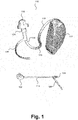
- Fig. 1 shows in perspective a BTE hearing aid 110 of the well-known type wherein sound signals propagate as acoustic signals from a receiver positioned in a hearing aid housing 112 worn behind the ear and through a sound tube 114 into the ear canal.
- a BTE hearing aid 110 is for example disclosed in EP 1 448 014 .
- the hearing aid housing 112 contains a battery, a microphone, a processor, and a receiver (not shown) for generating sound that is input into the sound tube 114.
- an earpiece 116 is attached to the sound tube 114 for insertion into the ear canal of the user.
- the sound tube 114 has a pre-formed shape for conducting sound from the hearing aid housing 112 to the ear canal (not shown).
- the pre-formed shape of the sound tube 114 includes a first bend 118 extending from the case over the top of the ear of the user and a second bend 120 extending from an outside of the ear into an ear canal of the user when the hearing aid 110 is worn by the user.
- the earpiece 116 is configured to fit within the ear canal and, preferably, allows sounds outside and within the ear to pass through the ear canal around the earpiece.
- a first end of the sound tube 114 is attached to a first connector 122 for coupling of the sound tube 114 to the BTE housing 112 containing the electronics of the hearing aid 110, and a second end of the sound tube 114 is attached to a second connector 124 for coupling of the sound tube 114 to the earpiece 116.
- the sound tube 114 is flexible so that the sound tube 114 is allowed to bend and provide the required arcuate propagation path of the sound from the receiver output.
- the second connector 124 comprises a plug to be connected with the earpiece 116 for attachment of the sound tube 114 to the earpiece.
- the hearing aid 110 has an arcuate, preferably resilient, fibre 126 with one end that is connected to the second connector 124.
- the fibre 126 is adapted for abutting a surface of the outer ear when the earpiece 116 has been inserted in the ear canal thereby providing retention of the earpiece 116 in the ear canal of the user.
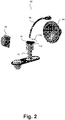
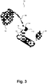
- FIGs. 2 and 3 show internal parts mounted in a test box for quality control and/or for adjustment of hearing aids.
- the walls of the test box have been left out so that the internal parts are visible.
- the test box 50 comprises a test microphone (not visible) positioned below a guiding member 52 possibly comprising a 2cc coupler, for reception and recording sound output by the hearing aid 110 to be tested.
- the member 10 is positioned at the upper end of the guiding member 52 and, except for the hole 14, closes the upper end of the guiding member 52 in a soundproof manner by insertion of a protrusion 24 inside the guiding member 52.
- the hearing aid housing 112 is positioned on a planar adhesive surface 16 of the member 10 and the second connector 124 of the sound tube 114 is inserted into the hole 14 of the member 10 in a soundproof way and thereby sound output by the hearing aid 110 is transmitted without disturbances to the test microphone of the test box.
- the adhesive is a reusable, pressure-sensitive adhesive so that the hearing aid housing 112 is easily and safely fixed to the adhesive surface 16 simply by pressing the housing 112 lightly onto the adhesive surface 16.
- the adhesive of the adhesive surface is preferably a low-tack adhesive that allows the hearing aid housing 112 to be easily attached to and removed from the adhesive surface 16 without leaving marks or residue on the hearing aid housing 112.
- the adhesive surface 16 is preferably provided with a protection sheet during manufacture of the member.
- the protection sheet is easily removed from the adhesive surface 16 before fixation of the hearing aid housing 112 to the adhesive surface 16.
- the adhesive may for example be formed by a double coated foam tape as for example manufactured by 3M.
- the second connector 124 is easily retracted from the hole 14, and the hearing aid housing 112 is easily removed from the adhesive surface 16.
- the member 10 may be re-used for testing of another hearing aid; or, the member 10 may be discarded after use.
- a front loudspeaker 54 and a rear loudspeaker 56 are positioned in the test box to generate sound during the test for reception and processing by the hearing aid 110 to be tested and the sound output by the hearing aid 110 is guided towards the test microphone.
- a reference microphone (not visible) is positioned at the end of a flexible hose 58 containing electrical wires for transmission of electrical signals from the reference microphone, so that the reference microphone can be positioned adjacent a microphone of the hearing aid 110 to be tested in order to measure the actual level of the sound received by the hearing aid 110.
- the test box 50 is sound proof so that sound from the surroundings is prevented from interfering with the testing of the hearing aid 110.
- the member 10 facilitates easy and convenient soundproof interconnection of a sound output of a BTE hearing aid 110 with a guiding member for guiding sound output by the hearing aid to the test microphone in the test box 50 and simultaneous fixation of the hearing aid housing 112 in an appropriate position in the test box 50 with relation to loudspeakers and the reference microphone in the test box thereby facilitating repeatable measurements.
- Figure 5 shows a photograph of a test box containing a guiding member 52, a hearing aid housing 112 and sound tube 114, a new member having an adhesive surface 16, and a loudspeaker 54.
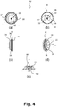
- Fig. 4 shows the member 10 in more detail in various side and elevational views and in perspective and cross-section, i.e. Fig. 4(a) is a bottom view of the member 10, Fig. 4(b) is a top view of the member, Fig. 4(c) is a side view of the member, Fig. 4(d) shows a bottom view of the member 10 in perspective, and Fig. 4(e) shows the part 22 made of flexible material in cross-section.
- Figure 6 shows an image of the member 10 comprising a protective sheet 18 removably positioned on an adhesive surface to be removed before fixation of the housing 112 to the member 10.
- the illustrated member 10 has the shape of a circular disc with protrusions and depressions and an outer circumference 20.
- the hole 14 of the member 10 is formed centrally in the member 10, and a part 22 of the member 10 accommodating the hole 14 is made of a flexible, resilient thermoplastic elastomer, so that the circumference of the hole 14 is flexible and configured to expand and automatically fit to the second connector 124 of the sound tube 114 when the sound tube 114 is inserted in the hole 14, whereby the output end of the sound tube 114 is connected to the member 10 in a sound proof way and in a simple and easy operation without the need for applying further material, such as Blu Tack, for provision of a sound proof interconnection.
- the central part 22 of the member made by a flexible and resilient thermoplastic elastomer is surrounded and held by a part of the member made of the hard material ABS.
- the member 10 is made by injection moulding.
- the two parts of the member 10 are fixed to each other by injection moulding one part onto the other part.
- the member 10 has a central protrusion 24 comprising the hole 14, wherein the central protrusion 24 is configured for insertion into a guiding member 52 in a sound proof way for conduction of sound emitted from the sound tube 114 inside the tubular member 52 towards the test microphone.
- the central protrusion 24 may have a circumferential ridge 34 protruding from the circumferential surface 36 abutting a surface of the guiding member 52 when the member 10 is mounted to the guiding member 52, whereby the member 10 and the guiding member 52 are interconnected with a press fit (snap fit).
- the guiding member 52 may have a groove matching the ridge 34 of the member 10 such that when the central protrusion 24 is inserted into the guiding member 52, the ridge 34 of the central protrusion 24 and the groove of the guiding member 52 may act as a tongue and groove.
- the guiding member comprises a groove in which an O-ring may be contained such that when the central protrusion 24 is inserted into the guiding member 52, the ridge 34 of the central protrusion 24 and O-ring in the groove of the guiding member 52 may interconnect in a sound proof manner.
- the member 10 has a central depression 26 comprising the hole 14 whereby the surface of the part of the member comprising the hole 14 is separated from the surface of the adhesive surface 16 whereby mutually non-interfering mounting is facilitated of the hearing aid housing 112 to the member 10 and the second connector 124 of the sound tube 114 in the hole 14 of the member 10.
- Part of the central depression 26 surrounding the flexible material with the hole 14 is made of the hard material ABS.
- the surface of the central depression 22 is non-adhesive.
- the central depression 26 defines an outer circumference 32 of the non-adhesive flexible and resilient surface 22.
- Reference 12 in figure 4 (b) may be a fastener such as an adhesive surface 16.
- Figure 4(c) shows the hard material such as ABS in reference 99.
- the inserted second connector 124 of the sound tube 114 is inserted such that it is flush with an end 98 of the member 10 facing the microphone positioned in the guiding member 52. Thereby is achieved a reproducible distance between the inserted second connector and the microphone positioned in the guiding member 52.
- Figure 6 shows an embodiment of the member 10 containing a protective sheet 18.
- the hard material part is shown as reference 99.
- the outer circumference of the member is referenced 20.
- the flexible material part is reference 22.
- the protrusion of the member is reference 24, and the central depression of the member is referenced 26.
- Figure 7 shows parts of the member 10 individually and in combination in perspective.
- Figure 7 (a) shows a protective sheet 18.
- Figure 7 (b) shows a double coated foam tape 97 providing at one side an adhesive surface 16 and at another side, opposite to the adhesive surface 16, a second adhesive surface for fixing the double coated foam tape 97 to a surface 716 of the hard material part 99 of the member 10.
- Figure 7 (c) shows a hard material part 99 of the member 10, a flexible material part 22 of the member 10 and a hole 14.
- the holes 96 placed in a concentric circle in the hard material part 99 of the member 10 are in an embodiment provided to prevent suction in the hard material part 99.
- Figure 7 (d) shows an embodiment of the member 10 comprising the protective sheet 18, the double coated foam tape 97, the hard material part 99, the flexible material part 22, and the hole 14.
- Figure 8 shows the member 10 in more detail in various side and perspective views in an embodiment wherein the fastener comprises mechanical fastening means for removably gripping and holding the hearing aid housing around a part of the housing.
- the fastener is embodied as a clamp 12.
- 52 represents the guiding member, 112 the hearing aid housing and 116 the earpiece inserted into the hole 14 in a soundproof manner.
- Figure 9 shows an embodiment, wherein the member 10 encloses the guiding member 52 in various side and perspective and cross-sectional views.
- the guiding member 52 is inserted into the member 10 which thereby encloses the guiding member 52 in a sound proof manner when an earpiece 116 of a hearing aid is inserted into the hole 14 of the member 10.
- 112 represents the housing
- 114 represents the sound tube
- 116 represents the earpiece
- 99 represents the hard material part of the member
- 16 represents the adhesive material surface
- 22 represents the flexible and resilient part of the member
- 80 represents the test microphone
- 81 represents a 2cc volume i.e. a 2 cubic centimetre volume of a 2cc coupler contained in the guiding member 52.
- the member 10 comprises a circumferential protrusion 924 made of the same material as the hard material part 99.
- the guiding member 52 is inserted into the member 10.
- the guiding member 52 comprises a groove 934 in which an O-ring may be contained.
- an inner surface of the circumferential protrusion 924 and the guiding member 52 may interconnect in a sound proof manner via the O-ring, when the member 10 encloses the guiding member 52.
- the protrusion 924 may comprise a circumferential ridge 934 corresponding to the O-ring above. The circumferential ridge 934 may protrude from the inner surface of the circumferential protrusion 924.
- the guiding member 52 comprises a groove matching the ridge of the protrusion 924 such that when the member 10 encloses the guiding member 52, the ridge 934 of the outer circumferential protrusion 924 and the groove of the guiding member 52 may act as a tongue and groove.
- Figure 10 shows an embodiment of the guiding member 52 of figures 2 and 3 together with the new member of figure 4 in cross-sectional view.
- 14 represents the hole in the new member 10
- 16 represents the adhesive surface
- 22 represents the flexible and resilient material part
- 99 represents the hard material part
- 81 represents the 2 cubic centimetre volume of the 2cc coupler of the guiding member 52
- 1005 represents a housing containing the test microphone 80
- 1002 represents a part of the housing 1005 containing the test microphone 80
- 1003 represents a volume/space for wires and/or cables from the microphone 80 to the test box, the connection between which is accommodated by a connector 1006, 1004 represents an O-ring providing sound proof connection between the housing 1005 containing the test microphone 80 and the test box
- 1001 represents a coupler between the two cubic centimetre volume 81 and the test microphone 80
- 1007 represents fixation means for fixing the microphone 80 to the housing 1005 such as e.g. tape and/or glue and/or a clamp.
- the O-ring 1004 may be substituted by a ridge in the housing 1005 matching a groove in the test box in a tongue and groove manner such as to ensure a sound proof connection between the housing 1005 and the test box.
Landscapes
- Health & Medical Sciences (AREA)
- General Health & Medical Sciences (AREA)
- Otolaryngology (AREA)
- Neurosurgery (AREA)
- Physics & Mathematics (AREA)
- Engineering & Computer Science (AREA)
- Acoustics & Sound (AREA)
- Signal Processing (AREA)
- Measurement Of The Respiration, Hearing Ability, Form, And Blood Characteristics Of Living Organisms (AREA)
Description
- A new member is provided for use in a test box for testing hearing aids.
- It is known to test hearing aids" in a test box for quality control and/or for adjustment purposes.
- In the test box, the sound output of the hearing aid to be tested is connected to a test microphone in a soundproof manner using an adaptor and a coupler such as a 2cc coupler. One or more loudspeakers in the test box generate sound during the test for reception and processing by the hearing aid to be tested and the sound output by the hearing aid is guided towards test microphone in the test box. A reference microphone is positioned adjacent a microphone of the hearing aid to be tested in order to measure the actual level of the sound received by the hearing aid. The test box is sound proof so that sound from the surroundings is prevented from interfering with the testing of the hearing aid.
-
US2009316921A disclose an apparatus for connecting a hearing aid tester to a sound emitting portion of a hearing aid that fits into the concha or ear canal of a user, the apparatus including a body having a front end and a rear end, a passage within the body for receiving the sound emitting portion and extending from an opening near the front end to an opening near the rear end, the opening near the front end for connecting the passage to the hearing aid tester, and a resilient surface within the passage that resiliently deforms when the sound emitting portion is received in the passage for retaining the sound emitting portion in the passage. The invention also includes a method of forming the apparatus and a method of testing a hearing aid having a sound emitting portion that fits into the concha or ear canal of a user. -
US2008304674A discloses a hearing device test adapter provided in order to connect a hearing device output to a test microphone in a soundproof manner. The hearing device test adapter has an expandable first section for enclosing one section of a hearing device shell or an earmold piece in a soundproof manner such that the sound output of the hearing device shell or of the earmold piece points to the tip of the first section. In addition, the hearing device test adapter has an expandable second section for enclosing a section of the test microphone in a soundproof manner, with the tip of the first section directly connecting to the second section and both being connected to one another via a sound transmission. - In order to properly test a hearing aid, it is important that the sound output of the hearing aid to be tested is connected to the test microphone in a soundproof manner. A behind-the-ear (BTE) hearing aid has a hearing aid housing worn behind the pinna of the user during use, and a sound tube for acoustical or electrical transmission of sound from a sound output of the hearing aid housing to an earpiece shaped for insertion into the ear canal of the user. The hearing aid housing may accommodate a receiver for outputting sound for acoustic transmission to the earpiece; or, the receiver may be accommodated in the earpiece in which case an electronic sound signal output by a processor in the hearing aid housing is transmitted electrically to the receiver in the earpiece inserted in the ear canal of the user during use.
- During test of a BTE hearing aid, an output end of the sound tube is connected to a metal guiding member (which may comprise a 2cc coupler) in the test box that guides sound generated by the hearing aid towards the test microphone. In an embodiment, the metal guiding member may be made of brass with dull chromium. The connection between the sound tube and the guiding member has to be sound proof so that sound generated by the test box does not enter the guiding member directly, and so that sound generated by the hearing aid cannot avoid entering the guiding member.
- The guiding member is provided with a metal adaptor comprising an opening substantially larger than the average output end of the sound tube in order to accommodate a wide range of output ends. The diameter of the opening of the adaptor may be twice the diameter of the average output end. In order to obtain a sound proof connection between the sound tube and the guiding member, the insertion of the output end of the sound tube with or without the earpiece as desired in the adaptor is achieved using a suitable wax, such as Blu tack, which is a reusable putty-like pressure-sensitive adhesive used for attaching paper items to walls. The adhesive material is applied to the output end of the sound tube and fixed to the adaptor around the opening when the output end of the sound tube has been inserted into the opening of the adaptor. The adaptor is subsequently inserted into the guiding member in a snap fit coupling.
- In order to obtain a sound proof connection, a skilled person has to apply the suitable wax, and applying the suitable wax is tedious, labour-intensive and time-consuming. A skilled person may achieve the sound proof connection in 2 - 4 minutes.
- After interconnecting the sound tube and the adaptor, the hearing aid housing may also be attached to the adaptor using more of the suitable wax to fix the housing to the adaptor. The reference microphone is positioned adjacent the current position of the microphone of the hearing aid.
- Thus, there is a need for an improved way of interconnecting a sound output of a BTE hearing aid with a test microphone in a test box in a reproducible and repeatable manner. Further, the suitable wax is normally reused and therefore becoming contaminated by the multiple usages. This may pose a health risk to the skilled person applying the suitable wax and a health risk to the patient (or the next patient). Thus, there is also a need to provide a more sterile testing of the hearing aid. Additionally, the reuse of the suitable wax may change the transmission properties of the suitable wax. Thus, there is a further need to make testing of the hearing aid reproducible and repeatable.
- Accordingly, a member according to the invention is defined in claim 1. The member is provided with a fastener for removable fixation of a housing of a hearing aid, and a hole for removable insertion of a sound tube of the hearing aid in sealing engagement with the member. The member may replace the abovementioned adaptor in order to ensure a sound proof connection between the member and the guiding member. Using the member, interconnection of the sound tube and the member and fixation of the housing to the member may be accomplished in under a minute e.g. in the order of 30 seconds.
- The fastener may comprise mechanical fastening means for removably gripping and holding the hearing aid housing around a part of the housing, for example shaped as a fork.
- The fastener may comprise an adhesive used for forming an adhesive surface of the member, such as a planar adhesive surface, suitable for removably mounting the hearing aid housing to the adhesive surface.
- The adhesive is preferably a reusable, pressure-sensitive adhesive so that the hearing aid housing is easily and safely fixed to the adhesive surface simply by pressing the housing lightly onto the adhesive surface thereby eliminating the need to non-reproducibly attaching the housing to the guiding member using blu-tack. Further, in combination with the hole for removable insertion of a sound tube in a sound proof engagement, the need for blu-tack is eliminated.
- Further, the adhesive of the adhesive surface is preferably a low-tack adhesive that allows the hearing aid housing to be easily attached to and removed from the adhesive surface without leaving marks or residue on the hearing aid housing.
- In order to protect the adhesive surface from contamination and to maintain the desired adhesive features of the adhesive surface during storage, the adhesive surface is preferably provided with a protection sheet during manufacture of the member. The protection sheet is easily removed from the adhesive surface before fixation of the hearing aid housing to the adhesive surface. In an embodiment, the protective sheet is made of paper coated with polyethylene. In another embodiment, the protective sheet is made of polytetrafluoroethylene (PTFE) or polyethylene (PE).
- The adhesive may for example be formed by a double coated foam tape as for example manufactured by 3M.
- For a BTE hearing aid with the receiver in the earpiece, i.e. a RIE hearing aid (RIE = Receiver In the Ear), the earpiece is inserted in the hole of the member, while for a BTE hearing aid with the receiver in the hearing aid housing, the output end of the sound tube may have a connector mating the earpiece so that the earpiece is removably fastened to the sound tube, and the connector may be inserted in the hole of the member for testing of the hearing aid without the earpiece. In both cases, an output end of the sound tube is said to be inserted into the hole of the member for sound proof interconnection of the sound tube with the member.
- The output end of the sound tube, e.g. a connector for an earpiece, or the earpiece itself, may be made of a flexible and resilient material, such as silicone, etc, so that an outer circumference of the output end of the sound tube is automatically fitted to the shape of the hole, during insertion of the output end of the sound tube into the hole, whereby the output end is connected to the member in a sound proof way in a simple and easy operation.
- A part of the member accommodating the hole is made of a flexible and resilient material, such as thermoplastic elastomers, thermoplastic polyurethanes, silicone, rubber, etc, so that the hole is flexible and may expand and automatically fit to the output end of the sound tube when the sound tube is inserted in the hole, whereby the output end is connected to the member in a sound proof way in a simple and easy operation without the need for applying suitable wax, such as Blu Tack, for provision of a sound proof interconnection.
- The part of the member made by a flexible and resilient material is surrounded and held by a part of the member made of a hard material, such as Acrylonitrile Butadiene Styrene (ABS), Polycarbonate Acrylonite Butadiene Styrene (PC/ABS), nylon, Polyamide (PA), etc.
- For example, a hard part of the member may be made of ABS while the flexible and the resilient part of the member may be made of a thermoplastic elastomer.
- A part of the member or all parts of the member may be made by injection moulding. The two parts of the member, i.e. the hard part and the flexible and resilient part, may be fixed to each other by injection moulding one part onto the other part; or the two parts of the member may be fixed to each other by gluing, ultrasound welding, bonding, etc.
- For example, the flexible and resilient material may be injection moulded onto the hard material.
- At least a part of an outer surface of the member is constituted by an adhesive surface, for example a part of the member made of a hard material may have the adhesive surface while a part of the member made of a flexible and resilient material and containing the hole has a non-adhesive surface.
- The member may be a planar member with a maximum height that is less than half its maximum width, e.g. shaped like a disc, a plate, etc.
- The member may have a substantially circular circumference.
- In the test box, sound output from the output end of the sound tube has to be guided to the test microphone without disturbances from other sounds, such as the sound generated by the loudspeaker(s) in the test chamber or sounds from the surroundings of the test chamber. Therefore, a guiding member is provided in the test box, typically a tubular guiding member with a circular cross-section, positioned so that the test microphone is located and enclosed at one end of the guiding member, while the member is mounted to the other end of the guiding member in a sound proof way.
- The member may have a central protrusion comprising the hole, wherein the central protrusion is configured for insertion into a tubular member in a sound proof way for conduction of sound emitted from the sound tube inside the tubular member towards the test microphone.
- The central protrusion may have a circumferential ridge protruding from the surface abutting a surface of the guiding member when the member is mounted to the guiding member, whereby the member and the guiding member are interconnected with a press fit.
- The member has a central depression comprising the hole whereby the plane of the central depression may be different from the plane of the member containing the fastener whereby mutually non-interfering mounting is facilitated of the hearing aid housing to the fastener and the output end of the sound tube in the hole of the member.
- Part of the central depression may be made of the hard material.
- Preferably, the central depression is non-adhesive.
- The central depression may define an inner circumference of the adhesive surface.
- The inner circumference may be substantially circular.
- Below, the new member will be described in more detail with reference to the examples illustrated in the drawings, wherein
- Fig. 1
- is a perspective view of a prior art BTE hearing aid with an earpiece, and the sound tube,
- Fig. 2
- is a schematic view of internal components of at test box,
- Fig. 3
- is a schematic view of internal components of at test box seen from another angle,
- Fig. 4
- shows various views of a new member, and
- Fig. 5
- is a photo of utilisation of a new member in a test box.
- Fig. 6
- shows an embodiment of the new member containing the protective sheet.
- Fig. 7
- shows an embodiment in which multiple parts of the new member are shown individually and in combination.
- Fig. 8
- shows an embodiment where the fastener is embodied as a clamp.
- Fig. 9
- shows an embodiment, wherein the new member encloses the guiding member (comprising a 2cc coupler).
- Fig. 10
- shows an embodiment of the guiding
member 52 infigures 2 and3 together with the new member offigure 4 . - The new member will now be described more fully hereinafter with reference to the accompanying drawings, in which various examples are shown.
- The accompanying drawings are schematic and simplified for clarity, and they merely show details which are essential to the understanding of the invention, while other details have been left out.
- The invention may be embodied in different forms not shown in the accompanying drawings and should not be construed as limited to the examples set forth herein. Rather, these examples are provided so that this disclosure will be thorough and complete, and will fully convey the scope of the invention to those skilled in the art.
- Like reference numerals refer to like elements throughout.
-
Fig. 1 shows in perspective aBTE hearing aid 110 of the well-known type wherein sound signals propagate as acoustic signals from a receiver positioned in ahearing aid housing 112 worn behind the ear and through asound tube 114 into the ear canal. Such aBTE hearing aid 110 is for example disclosed inEP 1 448 014 . - The
hearing aid housing 112 contains a battery, a microphone, a processor, and a receiver (not shown) for generating sound that is input into thesound tube 114. - In order to position the
sound tube 114 securely and comfortably in the ear canal, anearpiece 116 is attached to thesound tube 114 for insertion into the ear canal of the user. - The
sound tube 114 has a pre-formed shape for conducting sound from thehearing aid housing 112 to the ear canal (not shown).The pre-formed shape of thesound tube 114 includes afirst bend 118 extending from the case over the top of the ear of the user and asecond bend 120 extending from an outside of the ear into an ear canal of the user when thehearing aid 110 is worn by the user. - The
earpiece 116 is configured to fit within the ear canal and, preferably, allows sounds outside and within the ear to pass through the ear canal around the earpiece. - A first end of the
sound tube 114 is attached to afirst connector 122 for coupling of thesound tube 114 to theBTE housing 112 containing the electronics of thehearing aid 110, and a second end of thesound tube 114 is attached to asecond connector 124 for coupling of thesound tube 114 to theearpiece 116. Thesound tube 114 is flexible so that thesound tube 114 is allowed to bend and provide the required arcuate propagation path of the sound from the receiver output. - The
second connector 124 comprises a plug to be connected with theearpiece 116 for attachment of thesound tube 114 to the earpiece. - Further, the
hearing aid 110 has an arcuate, preferably resilient,fibre 126 with one end that is connected to thesecond connector 124. Thefibre 126 is adapted for abutting a surface of the outer ear when theearpiece 116 has been inserted in the ear canal thereby providing retention of theearpiece 116 in the ear canal of the user. - From different viewing angles,
Figs. 2 and3 show internal parts mounted in a test box for quality control and/or for adjustment of hearing aids. The walls of the test box have been left out so that the internal parts are visible. - The
test box 50 comprises a test microphone (not visible) positioned below a guidingmember 52 possibly comprising a 2cc coupler, for reception and recording sound output by thehearing aid 110 to be tested. - The
member 10 is positioned at the upper end of the guidingmember 52 and, except for thehole 14, closes the upper end of the guidingmember 52 in a soundproof manner by insertion of aprotrusion 24 inside the guidingmember 52. - The
hearing aid housing 112 is positioned on a planaradhesive surface 16 of themember 10 and thesecond connector 124 of thesound tube 114 is inserted into thehole 14 of themember 10 in a soundproof way and thereby sound output by thehearing aid 110 is transmitted without disturbances to the test microphone of the test box. - The adhesive is a reusable, pressure-sensitive adhesive so that the
hearing aid housing 112 is easily and safely fixed to theadhesive surface 16 simply by pressing thehousing 112 lightly onto theadhesive surface 16. - Further, the adhesive of the adhesive surface is preferably a low-tack adhesive that allows the
hearing aid housing 112 to be easily attached to and removed from theadhesive surface 16 without leaving marks or residue on thehearing aid housing 112. - In order to protect the
adhesive surface 16 from contamination and to maintain the desired adhesive features of theadhesive surface 16 during storage, theadhesive surface 16 is preferably provided with a protection sheet during manufacture of the member. The protection sheet is easily removed from theadhesive surface 16 before fixation of thehearing aid housing 112 to theadhesive surface 16. - The adhesive may for example be formed by a double coated foam tape as for example manufactured by 3M.
- When the test has been finished, the
second connector 124 is easily retracted from thehole 14, and thehearing aid housing 112 is easily removed from theadhesive surface 16. Themember 10 may be re-used for testing of another hearing aid; or, themember 10 may be discarded after use. - A
front loudspeaker 54 and arear loudspeaker 56 are positioned in the test box to generate sound during the test for reception and processing by thehearing aid 110 to be tested and the sound output by thehearing aid 110 is guided towards the test microphone. A reference microphone (not visible) is positioned at the end of aflexible hose 58 containing electrical wires for transmission of electrical signals from the reference microphone, so that the reference microphone can be positioned adjacent a microphone of thehearing aid 110 to be tested in order to measure the actual level of the sound received by thehearing aid 110. - The
test box 50 is sound proof so that sound from the surroundings is prevented from interfering with the testing of thehearing aid 110. - Thus, the
member 10 facilitates easy and convenient soundproof interconnection of a sound output of aBTE hearing aid 110 with a guiding member for guiding sound output by the hearing aid to the test microphone in thetest box 50 and simultaneous fixation of thehearing aid housing 112 in an appropriate position in thetest box 50 with relation to loudspeakers and the reference microphone in the test box thereby facilitating repeatable measurements. -
Figure 5 shows a photograph of a test box containing a guidingmember 52, ahearing aid housing 112 andsound tube 114, a new member having anadhesive surface 16, and aloudspeaker 54. -
Fig. 4 shows themember 10 in more detail in various side and elevational views and in perspective and cross-section, i.e.Fig. 4(a) is a bottom view of themember 10,Fig. 4(b) is a top view of the member,Fig. 4(c) is a side view of the member,Fig. 4(d) shows a bottom view of themember 10 in perspective, andFig. 4(e) shows thepart 22 made of flexible material in cross-section.Figure 6 shows an image of themember 10 comprising aprotective sheet 18 removably positioned on an adhesive surface to be removed before fixation of thehousing 112 to themember 10. - The illustrated
member 10 has the shape of a circular disc with protrusions and depressions and anouter circumference 20. Thehole 14 of themember 10 is formed centrally in themember 10, and apart 22 of themember 10 accommodating thehole 14 is made of a flexible, resilient thermoplastic elastomer, so that the circumference of thehole 14 is flexible and configured to expand and automatically fit to thesecond connector 124 of thesound tube 114 when thesound tube 114 is inserted in thehole 14, whereby the output end of thesound tube 114 is connected to themember 10 in a sound proof way and in a simple and easy operation without the need for applying further material, such as Blu Tack, for provision of a sound proof interconnection. Thecentral part 22 of the member made by a flexible and resilient thermoplastic elastomer is surrounded and held by a part of the member made of the hard material ABS. - The
member 10 is made by injection moulding. - The two parts of the
member 10 are fixed to each other by injection moulding one part onto the other part. - The
member 10 has acentral protrusion 24 comprising thehole 14, wherein thecentral protrusion 24 is configured for insertion into a guidingmember 52 in a sound proof way for conduction of sound emitted from thesound tube 114 inside thetubular member 52 towards the test microphone. - The
central protrusion 24 may have acircumferential ridge 34 protruding from thecircumferential surface 36 abutting a surface of the guidingmember 52 when themember 10 is mounted to the guidingmember 52, whereby themember 10 and the guidingmember 52 are interconnected with a press fit (snap fit). In an embodiment, the guidingmember 52 may have a groove matching theridge 34 of themember 10 such that when thecentral protrusion 24 is inserted into the guidingmember 52, theridge 34 of thecentral protrusion 24 and the groove of the guidingmember 52 may act as a tongue and groove. In an embodiment, the guiding member comprises a groove in which an O-ring may be contained such that when thecentral protrusion 24 is inserted into the guidingmember 52, theridge 34 of thecentral protrusion 24 and O-ring in the groove of the guidingmember 52 may interconnect in a sound proof manner. - The
member 10 has acentral depression 26 comprising thehole 14 whereby the surface of the part of the member comprising thehole 14 is separated from the surface of theadhesive surface 16 whereby mutually non-interfering mounting is facilitated of thehearing aid housing 112 to themember 10 and thesecond connector 124 of thesound tube 114 in thehole 14 of themember 10. - Part of the
central depression 26 surrounding the flexible material with thehole 14 is made of the hard material ABS. The surface of thecentral depression 22 is non-adhesive. - In
figure 4(b) , thecentral depression 26 defines anouter circumference 32 of the non-adhesive flexible andresilient surface 22.Reference 12 infigure 4 (b) may be a fastener such as anadhesive surface 16. -
Figure 4(c) shows the hard material such as ABS inreference 99. - In
figure 4(e) , the insertedsecond connector 124 of thesound tube 114 is inserted such that it is flush with anend 98 of themember 10 facing the microphone positioned in the guidingmember 52. Thereby is achieved a reproducible distance between the inserted second connector and the microphone positioned in the guidingmember 52. -
Figure 6 shows an embodiment of themember 10 containing aprotective sheet 18. The hard material part is shown asreference 99. The outer circumference of the member is referenced 20. The flexible material part isreference 22. The protrusion of the member isreference 24, and the central depression of the member is referenced 26. -
Figure 7 shows parts of themember 10 individually and in combination in perspective.Figure 7 (a) shows aprotective sheet 18.Figure 7 (b) shows a doublecoated foam tape 97 providing at one side anadhesive surface 16 and at another side, opposite to theadhesive surface 16, a second adhesive surface for fixing the doublecoated foam tape 97 to asurface 716 of thehard material part 99 of themember 10.Figure 7 (c) shows ahard material part 99 of themember 10, aflexible material part 22 of themember 10 and ahole 14. Theholes 96 placed in a concentric circle in thehard material part 99 of themember 10 are in an embodiment provided to prevent suction in thehard material part 99.Figure 7 (d) shows an embodiment of themember 10 comprising theprotective sheet 18, the doublecoated foam tape 97, thehard material part 99, theflexible material part 22, and thehole 14. -
Figure 8 shows themember 10 in more detail in various side and perspective views in an embodiment wherein the fastener comprises mechanical fastening means for removably gripping and holding the hearing aid housing around a part of the housing. In this embodiment, the fastener is embodied as aclamp 12. Infigure 8 , 52 represents the guiding member, 112 the hearing aid housing and 116 the earpiece inserted into thehole 14 in a soundproof manner. -
Figure 9 shows an embodiment, wherein themember 10 encloses the guidingmember 52 in various side and perspective and cross-sectional views. In this embodiment, the guidingmember 52 is inserted into themember 10 which thereby encloses the guidingmember 52 in a sound proof manner when anearpiece 116 of a hearing aid is inserted into thehole 14 of themember 10. In this embodiment, 112 represents the housing, 114 represents the sound tube, 116 represents the earpiece, 99 represents the hard material part of themember member member 52. - The
member 10 comprises acircumferential protrusion 924 made of the same material as thehard material part 99. The guidingmember 52 is inserted into themember 10. In an embodiment, the guidingmember 52 comprises agroove 934 in which an O-ring may be contained. Thereby, an inner surface of thecircumferential protrusion 924 and the guidingmember 52 may interconnect in a sound proof manner via the O-ring, when themember 10 encloses the guidingmember 52. In an embodiment, theprotrusion 924 may comprise acircumferential ridge 934 corresponding to the O-ring above. Thecircumferential ridge 934 may protrude from the inner surface of thecircumferential protrusion 924. In this embodiment, the guidingmember 52 comprises a groove matching the ridge of theprotrusion 924 such that when themember 10 encloses the guidingmember 52, theridge 934 of the outercircumferential protrusion 924 and the groove of the guidingmember 52 may act as a tongue and groove. -
Figure 10 shows an embodiment of the guidingmember 52 offigures 2 and3 together with the new member offigure 4 in cross-sectional view. 14 represents the hole in thenew member member test microphone housing 1005 containing thetest microphone microphone 80 to the test box, the connection between which is accommodated by aconnector housing 1005 containing thetest microphone 80 and the test box, 1001 represents a coupler between the twocubic centimetre volume 81 and thetest microphone microphone 80 to thehousing 1005 such as e.g. tape and/or glue and/or a clamp. 934 represents the sound proof interconnection between themember 10 and the 2cc coupler part of guidingmember 52. - In an embodiment, the O-
ring 1004 may be substituted by a ridge in thehousing 1005 matching a groove in the test box in a tongue and groove manner such as to ensure a sound proof connection between thehousing 1005 and the test box.
Claims (13)
- A member (10) for testing of a hearing aid (110), the member (10) comprising:- a fastener (12) for removable fixation of a housing (112) of the hearing aid (110),- a hole (14) for removable insertion of a sound tube (114) of the hearing aid (110) in sound proof engagement with the member (10),wherein at least a part of the member (10) accommodating the hole (14) is made of a resilient material so that the hole (14) is flexible and configured to expand and adapt to the sound tube (114) when the sound tube (114) is inserted in the hole (14), and
wherein a part of the member (10) defining an outer circumference (20) of the member (10) is made of a hard material, and wherein the part (22) of the member made of the resilient material is fixed to the hard material. - A member (10) according to claim 1, wherein the fastener (12) comprises an adhesive.
- A member (10) according to claim 2, wherein the fastener (12) comprises a planar adhesive surface (16).
- A member (10) according to claim 3, with a protection sheet (18) removably positioned on the adhesive surface (16) to be removed before fixation of the housing (112).
- A member (10) according to any of the previous claims, wherein the part of the member (10) made of the hard material encloses the part (22) of the member made of the resilient material.
- A member (10) according to claims 3-5, wherein the adhesive surface (16) is contained on a surface of the member (10) made of the hard material.
- A member (10) according to any of the previous claims, wherein the resilient material is fixed to the hard material by injection moulding the resilient material onto the hard material.
- A member (10) according to any of the previous claims, wherein the member (10) is substantially circular.
- A member (10) according to any of the previous claims, having a central protrusion (24) comprising the hole (14), and wherein the central protrusion (24) is configured for insertion into a tubular member for conduction of sound emitted from the sound tube (114) inside the tubular member.
- A member (10) according to any of the previous claims, having a central depression (26) comprising the hole (14).
- A member (10) according to claim 10, wherein part (28) of the central depression is made of the hard material.
- A member (10) according to claim 10 or 11, wherein the central depression (26) is non-adhesive.
- A member (10) according to any of claims 10 - 12, wherein the central depression (26) defines an inner circumference (30) of the adhesive surface (16).
Priority Applications (3)
| Application Number | Priority Date | Filing Date | Title |
|---|---|---|---|
| EP12161498.6A EP2645747B1 (en) | 2012-03-27 | 2012-03-27 | A member with an adhesive surface |
| US13/439,798 US9426583B2 (en) | 2012-03-27 | 2012-04-04 | Member with an adhesive surface |
| CN201310102519.6A CN103369448B (en) | 2012-03-27 | 2013-03-27 | There is the component of tacky surfaces |
Applications Claiming Priority (1)
| Application Number | Priority Date | Filing Date | Title |
|---|---|---|---|
| EP12161498.6A EP2645747B1 (en) | 2012-03-27 | 2012-03-27 | A member with an adhesive surface |
Publications (2)
| Publication Number | Publication Date |
|---|---|
| EP2645747A1 EP2645747A1 (en) | 2013-10-02 |
| EP2645747B1 true EP2645747B1 (en) | 2020-02-26 |
Family
ID=45888072
Family Applications (1)
| Application Number | Title | Priority Date | Filing Date |
|---|---|---|---|
| EP12161498.6A Active EP2645747B1 (en) | 2012-03-27 | 2012-03-27 | A member with an adhesive surface |
Country Status (1)
| Country | Link |
|---|---|
| EP (1) | EP2645747B1 (en) |
Family Cites Families (4)
| Publication number | Priority date | Publication date | Assignee | Title |
|---|---|---|---|---|
| ATE308221T1 (en) | 2003-02-14 | 2005-11-15 | Gn Resound As | HOLDING ELEMENT FOR EARPIECE |
| AU2007252221B2 (en) * | 2006-05-24 | 2010-08-26 | Interacoustics A/S | Apparatus and method for connecting a hearing aid to hearing aid test equipment |
| DE102007026116A1 (en) * | 2007-06-05 | 2008-12-11 | Siemens Medical Instruments Pte. Ltd. | Hearing aids test adapter |
| US8363876B2 (en) * | 2007-12-14 | 2013-01-29 | Mednax Services, Inc. | Audiometric devices |
-
2012
- 2012-03-27 EP EP12161498.6A patent/EP2645747B1/en active Active
Non-Patent Citations (1)
| Title |
|---|
| None * |
Also Published As
| Publication number | Publication date |
|---|---|
| EP2645747A1 (en) | 2013-10-02 |
Similar Documents
| Publication | Publication Date | Title |
|---|---|---|
| AU2009357228B2 (en) | An ear plug for a hearing aid and a hearing aid | |
| CN212137926U (en) | Hearing device sub-assembly | |
| US8121320B2 (en) | Hearing aid | |
| KR101564522B1 (en) | Hearing aid with a bushing for an ear wax guard | |
| US12257076B2 (en) | Apparatus, which is insertable into an ear canal, for detecting physiological parameters | |
| CN101416530A (en) | Isolated deep ear canal wearing earphone | |
| US9473843B2 (en) | Integrated tube and dome for thin tube BTE | |
| US9258657B2 (en) | Method of manufacturing a soft custom ear mold and a soft custom ear mold | |
| CN101218851A (en) | Hearing aids and earphones for hearing aids | |
| EP2033483B1 (en) | Apparatus and method for connecting a hearing aid to hearing aid test equipment | |
| JP2008515299A (en) | Hearing aid adapter | |
| CN117998243A (en) | Ear-worn hearing device | |
| US20080304674A1 (en) | Hearing device test adapter | |
| US9426583B2 (en) | Member with an adhesive surface | |
| US8355519B2 (en) | Tool for fitting and removing a receiver of a hearing aid | |
| WO2009101142A1 (en) | Receiver module for a hearing device, hearing device and hearing device earpiece | |
| EP2645747A1 (en) | A member with an adhesive surface | |
| US20140193013A1 (en) | Hearing aid with an in-the-ear component | |
| EP2309779B1 (en) | Hearing device and earpiece | |
| US20150296314A1 (en) | Receiver/loudspeaker | |
| DK201470201A1 (en) | Hearing aid with a receiver | |
| EP4593413A1 (en) | Open-type earphone | |
| EP2930948A1 (en) | Hearing aid | |
| EP3086573B1 (en) | A hearing device configured to be placed in the ear canal of a user | |
| US20170048607A1 (en) | Headset |
Legal Events
| Date | Code | Title | Description |
|---|---|---|---|
| PUAI | Public reference made under article 153(3) epc to a published international application that has entered the european phase |
Free format text: ORIGINAL CODE: 0009012 |
|
| AK | Designated contracting states |
Kind code of ref document: A1 Designated state(s): AL AT BE BG CH CY CZ DE DK EE ES FI FR GB GR HR HU IE IS IT LI LT LU LV MC MK MT NL NO PL PT RO RS SE SI SK SM TR |
|
| AX | Request for extension of the european patent |
Extension state: BA ME |
|
| 17P | Request for examination filed |
Effective date: 20140401 |
|
| RBV | Designated contracting states (corrected) |
Designated state(s): AL AT BE BG CH CY CZ DE DK EE ES FI FR GB GR HR HU IE IS IT LI LT LU LV MC MK MT NL NO PL PT RO RS SE SI SK SM TR |
|
| STAA | Information on the status of an ep patent application or granted ep patent |
Free format text: STATUS: EXAMINATION IS IN PROGRESS |
|
| RAP1 | Party data changed (applicant data changed or rights of an application transferred) |
Owner name: NATUS MEDICAL INCORPORATED |
|
| 17Q | First examination report despatched |
Effective date: 20180627 |
|
| GRAP | Despatch of communication of intention to grant a patent |
Free format text: ORIGINAL CODE: EPIDOSNIGR1 |
|
| STAA | Information on the status of an ep patent application or granted ep patent |
Free format text: STATUS: GRANT OF PATENT IS INTENDED |
|
| INTG | Intention to grant announced |
Effective date: 20191018 |
|
| GRAS | Grant fee paid |
Free format text: ORIGINAL CODE: EPIDOSNIGR3 |
|
| GRAA | (expected) grant |
Free format text: ORIGINAL CODE: 0009210 |
|
| STAA | Information on the status of an ep patent application or granted ep patent |
Free format text: STATUS: THE PATENT HAS BEEN GRANTED |
|
| AK | Designated contracting states |
Kind code of ref document: B1 Designated state(s): AL AT BE BG CH CY CZ DE DK EE ES FI FR GB GR HR HU IE IS IT LI LT LU LV MC MK MT NL NO PL PT RO RS SE SI SK SM TR |
|
| REG | Reference to a national code |
Ref country code: GB Ref legal event code: FG4D |
|
| REG | Reference to a national code |
Ref country code: CH Ref legal event code: EP |
|
| REG | Reference to a national code |
Ref country code: DE Ref legal event code: R096 Ref document number: 602012068007 Country of ref document: DE |
|
| REG | Reference to a national code |
Ref country code: AT Ref legal event code: REF Ref document number: 1239148 Country of ref document: AT Kind code of ref document: T Effective date: 20200315 |
|
| REG | Reference to a national code |
Ref country code: IE Ref legal event code: FG4D |
|
| PG25 | Lapsed in a contracting state [announced via postgrant information from national office to epo] |
Ref country code: NO Free format text: LAPSE BECAUSE OF FAILURE TO SUBMIT A TRANSLATION OF THE DESCRIPTION OR TO PAY THE FEE WITHIN THE PRESCRIBED TIME-LIMIT Effective date: 20200526 Ref country code: FI Free format text: LAPSE BECAUSE OF FAILURE TO SUBMIT A TRANSLATION OF THE DESCRIPTION OR TO PAY THE FEE WITHIN THE PRESCRIBED TIME-LIMIT Effective date: 20200226 Ref country code: RS Free format text: LAPSE BECAUSE OF FAILURE TO SUBMIT A TRANSLATION OF THE DESCRIPTION OR TO PAY THE FEE WITHIN THE PRESCRIBED TIME-LIMIT Effective date: 20200226 |
|
| REG | Reference to a national code |
Ref country code: NL Ref legal event code: MP Effective date: 20200226 |
|
| REG | Reference to a national code |
Ref country code: LT Ref legal event code: MG4D |
|
| PG25 | Lapsed in a contracting state [announced via postgrant information from national office to epo] |
Ref country code: LV Free format text: LAPSE BECAUSE OF FAILURE TO SUBMIT A TRANSLATION OF THE DESCRIPTION OR TO PAY THE FEE WITHIN THE PRESCRIBED TIME-LIMIT Effective date: 20200226 Ref country code: SE Free format text: LAPSE BECAUSE OF FAILURE TO SUBMIT A TRANSLATION OF THE DESCRIPTION OR TO PAY THE FEE WITHIN THE PRESCRIBED TIME-LIMIT Effective date: 20200226 Ref country code: IS Free format text: LAPSE BECAUSE OF FAILURE TO SUBMIT A TRANSLATION OF THE DESCRIPTION OR TO PAY THE FEE WITHIN THE PRESCRIBED TIME-LIMIT Effective date: 20200626 Ref country code: GR Free format text: LAPSE BECAUSE OF FAILURE TO SUBMIT A TRANSLATION OF THE DESCRIPTION OR TO PAY THE FEE WITHIN THE PRESCRIBED TIME-LIMIT Effective date: 20200527 Ref country code: HR Free format text: LAPSE BECAUSE OF FAILURE TO SUBMIT A TRANSLATION OF THE DESCRIPTION OR TO PAY THE FEE WITHIN THE PRESCRIBED TIME-LIMIT Effective date: 20200226 Ref country code: BG Free format text: LAPSE BECAUSE OF FAILURE TO SUBMIT A TRANSLATION OF THE DESCRIPTION OR TO PAY THE FEE WITHIN THE PRESCRIBED TIME-LIMIT Effective date: 20200526 |
|
| PG25 | Lapsed in a contracting state [announced via postgrant information from national office to epo] |
Ref country code: NL Free format text: LAPSE BECAUSE OF FAILURE TO SUBMIT A TRANSLATION OF THE DESCRIPTION OR TO PAY THE FEE WITHIN THE PRESCRIBED TIME-LIMIT Effective date: 20200226 |
|
| PG25 | Lapsed in a contracting state [announced via postgrant information from national office to epo] |
Ref country code: CZ Free format text: LAPSE BECAUSE OF FAILURE TO SUBMIT A TRANSLATION OF THE DESCRIPTION OR TO PAY THE FEE WITHIN THE PRESCRIBED TIME-LIMIT Effective date: 20200226 Ref country code: RO Free format text: LAPSE BECAUSE OF FAILURE TO SUBMIT A TRANSLATION OF THE DESCRIPTION OR TO PAY THE FEE WITHIN THE PRESCRIBED TIME-LIMIT Effective date: 20200226 Ref country code: PT Free format text: LAPSE BECAUSE OF FAILURE TO SUBMIT A TRANSLATION OF THE DESCRIPTION OR TO PAY THE FEE WITHIN THE PRESCRIBED TIME-LIMIT Effective date: 20200719 Ref country code: ES Free format text: LAPSE BECAUSE OF FAILURE TO SUBMIT A TRANSLATION OF THE DESCRIPTION OR TO PAY THE FEE WITHIN THE PRESCRIBED TIME-LIMIT Effective date: 20200226 Ref country code: LT Free format text: LAPSE BECAUSE OF FAILURE TO SUBMIT A TRANSLATION OF THE DESCRIPTION OR TO PAY THE FEE WITHIN THE PRESCRIBED TIME-LIMIT Effective date: 20200226 Ref country code: EE Free format text: LAPSE BECAUSE OF FAILURE TO SUBMIT A TRANSLATION OF THE DESCRIPTION OR TO PAY THE FEE WITHIN THE PRESCRIBED TIME-LIMIT Effective date: 20200226 Ref country code: SM Free format text: LAPSE BECAUSE OF FAILURE TO SUBMIT A TRANSLATION OF THE DESCRIPTION OR TO PAY THE FEE WITHIN THE PRESCRIBED TIME-LIMIT Effective date: 20200226 Ref country code: SK Free format text: LAPSE BECAUSE OF FAILURE TO SUBMIT A TRANSLATION OF THE DESCRIPTION OR TO PAY THE FEE WITHIN THE PRESCRIBED TIME-LIMIT Effective date: 20200226 Ref country code: DK Free format text: LAPSE BECAUSE OF FAILURE TO SUBMIT A TRANSLATION OF THE DESCRIPTION OR TO PAY THE FEE WITHIN THE PRESCRIBED TIME-LIMIT Effective date: 20200226 |
|
| REG | Reference to a national code |
Ref country code: CH Ref legal event code: PL |
|
| REG | Reference to a national code |
Ref country code: AT Ref legal event code: MK05 Ref document number: 1239148 Country of ref document: AT Kind code of ref document: T Effective date: 20200226 |
|
| REG | Reference to a national code |
Ref country code: DE Ref legal event code: R097 Ref document number: 602012068007 Country of ref document: DE |
|
| PG25 | Lapsed in a contracting state [announced via postgrant information from national office to epo] |
Ref country code: MC Free format text: LAPSE BECAUSE OF FAILURE TO SUBMIT A TRANSLATION OF THE DESCRIPTION OR TO PAY THE FEE WITHIN THE PRESCRIBED TIME-LIMIT Effective date: 20200226 |
|
| REG | Reference to a national code |
Ref country code: BE Ref legal event code: MM Effective date: 20200331 |
|
| PG25 | Lapsed in a contracting state [announced via postgrant information from national office to epo] |
Ref country code: LU Free format text: LAPSE BECAUSE OF NON-PAYMENT OF DUE FEES Effective date: 20200327 |
|
| PLBE | No opposition filed within time limit |
Free format text: ORIGINAL CODE: 0009261 |
|
| STAA | Information on the status of an ep patent application or granted ep patent |
Free format text: STATUS: NO OPPOSITION FILED WITHIN TIME LIMIT |
|
| PG25 | Lapsed in a contracting state [announced via postgrant information from national office to epo] |
Ref country code: AT Free format text: LAPSE BECAUSE OF FAILURE TO SUBMIT A TRANSLATION OF THE DESCRIPTION OR TO PAY THE FEE WITHIN THE PRESCRIBED TIME-LIMIT Effective date: 20200226 Ref country code: IE Free format text: LAPSE BECAUSE OF NON-PAYMENT OF DUE FEES Effective date: 20200327 Ref country code: CH Free format text: LAPSE BECAUSE OF NON-PAYMENT OF DUE FEES Effective date: 20200331 Ref country code: LI Free format text: LAPSE BECAUSE OF NON-PAYMENT OF DUE FEES Effective date: 20200331 Ref country code: IT Free format text: LAPSE BECAUSE OF FAILURE TO SUBMIT A TRANSLATION OF THE DESCRIPTION OR TO PAY THE FEE WITHIN THE PRESCRIBED TIME-LIMIT Effective date: 20200226 |
|
| 26N | No opposition filed |
Effective date: 20201127 |
|
| PG25 | Lapsed in a contracting state [announced via postgrant information from national office to epo] |
Ref country code: BE Free format text: LAPSE BECAUSE OF NON-PAYMENT OF DUE FEES Effective date: 20200331 Ref country code: SI Free format text: LAPSE BECAUSE OF FAILURE TO SUBMIT A TRANSLATION OF THE DESCRIPTION OR TO PAY THE FEE WITHIN THE PRESCRIBED TIME-LIMIT Effective date: 20200226 Ref country code: PL Free format text: LAPSE BECAUSE OF FAILURE TO SUBMIT A TRANSLATION OF THE DESCRIPTION OR TO PAY THE FEE WITHIN THE PRESCRIBED TIME-LIMIT Effective date: 20200226 |
|
| PG25 | Lapsed in a contracting state [announced via postgrant information from national office to epo] |
Ref country code: TR Free format text: LAPSE BECAUSE OF FAILURE TO SUBMIT A TRANSLATION OF THE DESCRIPTION OR TO PAY THE FEE WITHIN THE PRESCRIBED TIME-LIMIT Effective date: 20200226 Ref country code: MT Free format text: LAPSE BECAUSE OF FAILURE TO SUBMIT A TRANSLATION OF THE DESCRIPTION OR TO PAY THE FEE WITHIN THE PRESCRIBED TIME-LIMIT Effective date: 20200226 Ref country code: CY Free format text: LAPSE BECAUSE OF FAILURE TO SUBMIT A TRANSLATION OF THE DESCRIPTION OR TO PAY THE FEE WITHIN THE PRESCRIBED TIME-LIMIT Effective date: 20200226 |
|
| PG25 | Lapsed in a contracting state [announced via postgrant information from national office to epo] |
Ref country code: MK Free format text: LAPSE BECAUSE OF FAILURE TO SUBMIT A TRANSLATION OF THE DESCRIPTION OR TO PAY THE FEE WITHIN THE PRESCRIBED TIME-LIMIT Effective date: 20200226 Ref country code: AL Free format text: LAPSE BECAUSE OF FAILURE TO SUBMIT A TRANSLATION OF THE DESCRIPTION OR TO PAY THE FEE WITHIN THE PRESCRIBED TIME-LIMIT Effective date: 20200226 |
|
| P01 | Opt-out of the competence of the unified patent court (upc) registered |
Effective date: 20230530 |
|
| PGFP | Annual fee paid to national office [announced via postgrant information from national office to epo] |
Ref country code: GB Payment date: 20260227 Year of fee payment: 15 |
|
| PGFP | Annual fee paid to national office [announced via postgrant information from national office to epo] |
Ref country code: DE Payment date: 20260309 Year of fee payment: 15 |
|
| PGFP | Annual fee paid to national office [announced via postgrant information from national office to epo] |
Ref country code: FR Payment date: 20260227 Year of fee payment: 15 |