EP2645506A1 - Electrical apparatus - Google Patents
Electrical apparatus Download PDFInfo
- Publication number
- EP2645506A1 EP2645506A1 EP10859953.1A EP10859953A EP2645506A1 EP 2645506 A1 EP2645506 A1 EP 2645506A1 EP 10859953 A EP10859953 A EP 10859953A EP 2645506 A1 EP2645506 A1 EP 2645506A1
- Authority
- EP
- European Patent Office
- Prior art keywords
- fuse
- cover body
- housing
- cover member
- projection section
- Prior art date
- Legal status (The legal status is an assumption and is not a legal conclusion. Google has not performed a legal analysis and makes no representation as to the accuracy of the status listed.)
- Granted
Links
Images


Classifications
-
- H—ELECTRICITY
- H02—GENERATION; CONVERSION OR DISTRIBUTION OF ELECTRIC POWER
- H02H—EMERGENCY PROTECTIVE CIRCUIT ARRANGEMENTS
- H02H1/00—Details of emergency protective circuit arrangements
- H02H1/0038—Details of emergency protective circuit arrangements concerning the connection of the detecting means, e.g. for reducing their number
-
- H—ELECTRICITY
- H01—ELECTRIC ELEMENTS
- H01H—ELECTRIC SWITCHES; RELAYS; SELECTORS; EMERGENCY PROTECTIVE DEVICES
- H01H85/00—Protective devices in which the current flows through a part of fusible material and this current is interrupted by displacement of the fusible material when this current becomes excessive
- H01H85/02—Details
- H01H85/24—Means for preventing insertion of incorrect fuse
-
- H—ELECTRICITY
- H02—GENERATION; CONVERSION OR DISTRIBUTION OF ELECTRIC POWER
- H02H—EMERGENCY PROTECTIVE CIRCUIT ARRANGEMENTS
- H02H5/00—Emergency protective circuit arrangements for automatic disconnection directly responsive to an undesired change from normal non-electric working conditions with or without subsequent reconnection
- H02H5/04—Emergency protective circuit arrangements for automatic disconnection directly responsive to an undesired change from normal non-electric working conditions with or without subsequent reconnection responsive to abnormal temperature
-
- H—ELECTRICITY
- H01—ELECTRIC ELEMENTS
- H01H—ELECTRIC SWITCHES; RELAYS; SELECTORS; EMERGENCY PROTECTIVE DEVICES
- H01H85/00—Protective devices in which the current flows through a part of fusible material and this current is interrupted by displacement of the fusible material when this current becomes excessive
- H01H85/0013—Means for preventing damage, e.g. by ambient influences to the fuse
- H01H85/0021—Means for preventing damage, e.g. by ambient influences to the fuse water or dustproof devices
- H01H85/0026—Means for preventing damage, e.g. by ambient influences to the fuse water or dustproof devices casings for the fuse and its base contacts
Definitions
- the present invention relates to electric apparatuses, particularly an electric apparatus including an overcurrent-protection fuse.
- Japanese Patent Laying-Open No. 2005-153827 discloses a configuration of a power storage device for a vehicle, including a base plate coupled to a side face of a battery, and having a recess provided at the side face corresponding to the battery side, wherein a main switch and main fuse are positioned in the recess.
- Japanese Patent Laying-Open No. 2005-153827 discloses a configuration of a power storage device for a vehicle, including a base plate coupled to a side face of a battery, and having a recess provided at the side face corresponding to the battery side, wherein a main switch and main fuse are positioned in the recess.
- PTL 2 9-148753
- PTL 3 discloses a transformer for an inverter, configured such that one end of a flange of the surface cover extends outward horizontally in contact to form a canopy section with a thermal fuse mounted at the upper portion of the canopy section.
- Japanese Patent Laying-Open No. 2004-48858 discloses a configuration in which a drain port is provided at the bottom wall of the box, including a notch continuous with the drain port, and an inclination section at the outer side of the bottom wall, becoming thinner towards the perimeter of the drain port, wherein the inclination section is provided with a drainage groove.
- the burned fuse In order to restart an electric circuit after a current exceeding the rating flows to the electric circuit to cause the fuse to blow out, the burned fuse must be exchanged.
- This fuse exchange is implemented by taking out the burned fuse from a storage space provided at the electrical apparatus for storing a fuse, and then attaching a new fuse at the storage space. At this stage, the new fuse may be erroneously attached upside down in the storage space.
- a main object of the present invention is to provide an electrical apparatus that can prevent erroneous attachment of a fuse.
- An electrical apparatus includes a housing having a surface.
- the housing has a space formed inside.
- the space communicates with a region outside of the housing through an opening formed at the surface.
- the electrical apparatus further includes a cover member covering the opening, and an overcurrent-protection fuse located in the space.
- the cover member includes a cover body closing the opening, a projection section protruding inward of the space relative to the cover body. When the fuse is attached erroneously in the space, the projection section interferes with the fuse.
- the cover body and projection section are a unitary molding made of metal.
- the cover body is formed plate-like, and the projection section is formed denting in a direction from the side of an outer face towards the side of an inner face of the cover body.
- the housing is arranged such that the surface has an inclination of a first angle with respect to a horizontal plane.
- the projection section has a dent bottom constituting a bottom face in a shape denting in the direction from the side of the outer face towards the side of the inner face of the cover body.
- the dent bottom joins the cover body at the lower side of the inclination of the housing, and is inclined having a second angle with respect to the cover body. The second angle is smaller than the first angle.
- an electrical apparatus of the present invention erroneous attachment of a fuse to the electrical apparatus can be prevented.
- Fig. 1 is a perspective view of an exemplified structure of an electrical apparatus according to an embodiment.
- a PCU (Power Control Unit) 1 mounted on a vehicle is illustrated as an example of an electrical apparatus.
- PCU 1 includes, in a housing 20, a MG (Motor Generator)-ECU (Electronic Control Unit) 11, an inverter, a boost converter, and a DC (Direct Current)-DC converter 15 integrally.
- the inverter and boost converter are mainly constituted of an IPM (Intelligent Power Module) 12 for running and boosting, a reactor 13, and a capacitor 14.
- IPM Intelligent Power Module
- MG-ECU 11 controls the inverter and boost converter according to output request values from the control device.
- the boost converter boosts the battery voltage to drive the motor generator at high voltage.
- the inverter converts the high-voltage DC current boosted by boost converter into AC current for supply to the motor generator.
- the inverter converts the generated AC current into DC current.
- DC-DC converter 15 down-converts the battery voltage for supply to an auxiliary and/or auxiliary battery.
- An opening 22 is formed at a surface 21 of housing 20.
- a fuse storage space 40 (not shown in Fig. 1 ) is formed for the purpose of storing a fuse 41.
- Fuse storage space 40 communicates with a region outside of housing 20 via opening 22.
- openings 23, 24 and 25 are formed at surface 21 of housing 20. Openings 22, 23, 24 and 25 are covered with a cover member 30.
- cover member 30 In the state of use where PCU 1 is mounted on the vehicle, cover member 30 is fixed to housing 20 to seal the interior of housing 20. By removing cover member 30 from housing 20 at the stage of maintenance, maintenance service of PCU 1 can be carried out such as exchanging fuse 41 in fuse storage space 40.
- An interlock switch 16 sensing an attached state is provided at cover member 30. Additionally, an interlock switch 17 is provided at the power cable input section towards PCU 1. Interlock switches 16 and 17 are turned OFF when cover member 30 is removed from housing 20, or when the power cable is cut to disconnect the system main relay.
- a coolant device is provided for cooling PCU 1.
- a coolant inlet 18 for supplying coolant into the coolant device and a coolant outlet 19 for discharge from the coolant device are provided at housing 20.
- Fig. 2 is a perspective view showing in enlargement a portion of cover member 30 of Fig. 1 .
- Fig. 3 is a sectional view representing a state where cover member 30 covers fuse storage space 40. Under the state shown in Fig. 3 , cover member 30 is fixed to a surface 21 of housing 20, closing opening 22 (refer to Fig. 1 ) formed at surface 21 of housing 20. Therefore, in the state shown in Fig. 3 , fuse storage space 40 and the region outside of housing 20 are partitioned by cover member 30, attaining a state not communicating with each other.
- cover member 30 includes a cover body 35, and a projection section 31 constituted of a portion of cover member 30 protruding inwards of fuse storage space 40 relative to cover body 35.
- Cover body 35 is formed plate-like.
- Plate-like cover body 35 includes an outer face 36 located at the side corresponding to the outer space of housing 20, and an inner face 37 facing fuse storage space 40.
- Projection section 31 is formed denting in the direction from the side of outer face 36 towards the side of inner face 37 of plate-like cover body 35.
- PCU 1 includes devices such as an inverter generating an electromagnetic wave in housing 20.
- devices such as an inverter generating an electromagnetic wave in housing 20.
- an electromagnetic wave shield room surrounding the devices with a conductive plate member must be formed to block the propagation of electromagnetic waves.
- cover member 30 is a resin molding
- opening 22 provided at housing 20 will correspond to a through hole for electrical conduction, causing the electromagnetic wave to leak outside through the through hole. Therefore, to suppress outward leakage of the electromagnetic wave from the interior of housing 20, cover body 35 and projection section 31 constituting cover member 30 are formed as a unitary molding made of metal.
- Cover body 35 and projection section 31 can be formed integrally by applying an arbitrary plastic forming process such as press-working to a steel plate.
- an arbitrary plastic forming process such as press-working to a steel plate.
- projection section 31 is formed to have a shape denting in the direction from the side of outer face 36 towards the side of inner face 37 of cover body 35, when viewed from the side of outer face 36 of cover body 35.
- Projection section 31 includes a dent bottom 32 constituting a bottom face in a shape denting in the direction from the side of outer face 36 towards the side of inner face 37 of cover body 35, and a side face 33 constituting an inner wall of the dent shape.
- Side face 33 is formed extending in a direction substantially orthogonal to plate-like cover body 35.
- Dent bottom 32 joins cover body 35 at a boundary 39, and joins side face 33 at a boundary 38.
- the perimeter of dent bottom 32 is constituted of boundary 38 and boundary 39.
- boundary 39 extending linearly constitutes the boundary between cover body 35 and dent bottom 32
- boundary 38 extending in a C-shape constitutes the boundary between side face 33 and dent bottom 32
- Dent bottom 32 has a portion of the perimeter directly connected with cover body 35 at boundary 39, whereas the remaining portion of the perimeter is connected with side face 33 at boundary 38.
- Boundary 38 is provided at the end corresponding to the side of side face 33 away from cover body 35. As a result, dent bottom 32 is arranged inclining at a predetermined angle relative to the plane direction of cover body 35.
- a fuse 41 that is blown out when a current greater than a tolerable value flows is located in fuse storage space 40 as an example of the space formed in housing 20.
- Fuse 41 is an overcurrent-protection element that cuts off the current by having a fusible element made of metal with a low melting point burned out when excessive current flows.
- Fuse 41 includes two junctions 42 and 43 extending outwards from the body. By the contact between a terminal 46 and junction 42 arranged in proximity to fuse 41 and the fixture through an attachment bolt 44, fuse 41 and terminal 46 are electrically connected. By the contact between a terminal 47 and junction 43 arranged in proximity to fuse 41 and the fixture through an attachment bolt 45, fuse 41 and terminal 47 are electrically connected. Terminals 46 and 47 constitute a portion of an electric circuit connected to the inverter, for example. By the fixture of junctions 42 and 43 by means of attachment bolts 44 and 45, fuse 41 is secured in fuse storage space 40.
- Attachment of fuse 41 in fuse storage space 40 is implemented by screwing using attachment bolts 44 and 45. At this stage, there may be the case where new fuse 41 is arranged by attachment bolts 44 and 45 erroneously in an opposite posture in fuse storage space 40, so that new fuse 41 is attached upside down.
- cover member 30 has a projection section 31 protruding inward of fuse storage space 40. If cover member 30 is to be attached to housing 20 when fuse 41 is erroneously assembled in fuse storage space 40, cover member 30 cannot be closed since projection section 31 interferes with a fuse 41. Therefore, the worker carrying out the exchanging job of fuse 41 can reliably confirm that fuse 41 has been erroneously assembled, allowing fuse 41 to be reattached properly. Therefore, the inconvenience of fuse 41 being attached in an opposite posture to cause short-circuiting between cover member 30 and fuse 41 can be prevented reliably.
- Fig. 4 is a sectional view representing a state where fuse 41 is attached upside down.
- the main body of fuse 41 is located at the lower side relative to junctions 42 and 43, remote from cover member 30, in Fig. 3 where fuse 41 is attached properly.
- the main body of fuse 41 is located at the upper side relative to junctions 42 and 43, in proximity to cover member 30.
- cover member 30 of Fig. 3 corresponds to the state fixed to surface 21 of housing 20.
- Cover member 30 indicated by a dashed double-dotted line in Fig. 4 corresponds to the state representing the arrangement of cover member 30 corresponding to the case fixed to surface 21 of housing 20, likewise with that shown in Fig. 3 .
- cover member 30 If cover member 30 is attached in a normal manner to housing 20 under the state where fuse 41 shown in Fig. 4 is erroneously attached in fuse storage space 40, projection section 31 will interfere with fuse 41, as indicated by the dashed double-dotted line in Fig. 4 . In practice, cover member 30 cannot be attached to housing 20. Therefore, when fuse 41 is erroneously attached in an exchanging job of fuse 41, the worker can reliably confirm the erroneous attachment to allow correction. Therefore, attachment of fuse 41 in an upside down manner can be prevented reliably.
- Fig. 5 is a sectional view representing a state where cover member 30 is arranged having an inclination relative to the horizontal plane.
- housing 20 is arranged such that surface 21 thereof has an inclination of a first angle ⁇ with respect to horizontal plane 100. Therefore, cover member 30 attached to surface 21 of housing 20 has plate-like cover body 35 inclined at an angle ⁇ with respect to horizontal plane 100. Cover body 35 in the plane direction forms an angle ⁇ relative to horizontal plane 100.
- Cover member 30 having cover body 35 arranged in an inclined manner to horizontal plane 100 is arranged such that dent bottom 32 of projection section 31 joins cover body 35 at the lower side of the inclination of housing 20.
- Dent bottom 32 constitutes a bottom face of a denting configuration in the direction from the side of outer face 36 towards the side of inner face 37 of plate-like cover body 35.
- Cover member 30 is arranged such that boundary 39 corresponding to the joining position between dent bottom 32 and cover body 35, along the perimeter of dent bottom 32, is located at the downmost side of the inclination of cover body 35.
- Dent bottom 32 shown in Fig. 5 is formed plate-like. As used herein, the plane direction of dent bottom 32 formed in plate shape and the plane direction of plate-like cover body 35 constitute a second angle ⁇ . Dent bottom 32 has an inclination of an angle ⁇ relative to cover body 35. As shown in Fig. 5 , cover body 35 and dent bottom 32 cross each other, forming an angle ⁇ at boundary 39.
- angle ⁇ is smaller than angle ⁇ .
- cover member 30 is formed such that the inclining angle of dent bottom 32 relative to cover body 35 is less than 18°. Therefore, as shown in Fig. 5 , boundary 39 corresponding to the joining position between dent bottom 32 and cover body 35 is located more downwards than boundary 38 corresponding to the joining position between dent bottom 32 and side face 33 in the vertical direction perpendicular to horizontal plane 100.
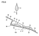
- Fig. 6 is a sectional view representing an example in which droplets enter the projection section of the cover member shown in Fig. 5 .
- dent bottom 32 has a positive angle ( ⁇ - ⁇ ) relative to horizontal plane 100.
- Dent bottom 32 is inclined relative to horizontal plane 100, forming an angle ( ⁇ - ⁇ ).
- Boundary 38 is located at the upper side of the inclination of dent bottom 32, and boundary 39 is located at the lower side of the inclination of dent bottom 32.
- Cover member 30 is arranged such that boundary 39 where dent bottom 32 is directly joined with cover body 35 is located at the downmost side of the inclination of dent bottom 32 arranged in an inclined manner relative to horizontal plane 100.
- cover member 30 of the present embodiment can have corrosive liquid promptly discharged from the dent formed at the outer face of cover body 35, as described above. Therefore, occurrence of corrosion at cover member 30 can be suppressed. Thus, a cover member 30 of longer lifetime and high reliability can be provided.
- Dent bottom 32 shown in Figs. 5 and 6 has, but is not limited to, a plate-like shape of the present embodiment.
- dent bottom 32 may have a shape in which a plurality of flat plates inflexed with respect to each other are assembled, or may have a curved shape such as a paraboloid.
- dent bottom 32 is formed such that the angle between dent bottom 32 and cover body 35 is small at the upper side of the inclination of inclined cover body 35 and becomes larger in incremental steps at the lower side of the inclination.
- dent bottom 32 is to have a curved shape
- dent bottom 32 is to be formed such that the angle between the tangent plane of dent bottom 32 and cover body 35 is monotonically increased as dent bottom 32 approaches boundary 39.
- the maximum angle formed between dent bottom 32 and cover body 35 is set smaller than angle ⁇ of cover body 35 inclined relative to horizontal plane 100. Accordingly, a configuration in which the corrosive liquid flows out by itself from the dent can be provided, preventing the corrosive liquid from remaining in the dent.
Landscapes
- Fuses (AREA)
- Connection Or Junction Boxes (AREA)
- Casings For Electric Apparatus (AREA)
Abstract
Description
- The present invention relates to electric apparatuses, particularly an electric apparatus including an overcurrent-protection fuse.
- Conventionally, various approaches have been proposed in association with an electrical apparatus including a fuse. For example, Japanese Patent Laying-Open No.
2005-153827 9-148753 5-11421 - In association with a drainage structure of an electrical component storage box, Japanese Patent Laying-Open No.
2004-48858 -
- PTL 1: Japanese Patent Laying-Open No.
2005-153827 - PTL 2: Japanese Patent Laying-Open No.
9-148753 - PTL 3: Japanese Utility Model Laying-Open No.
5-11421 - PTL 4: Japanese Patent Laying-Open No.
2004-48858 - In order to restart an electric circuit after a current exceeding the rating flows to the electric circuit to cause the fuse to blow out, the burned fuse must be exchanged. This fuse exchange is implemented by taking out the burned fuse from a storage space provided at the electrical apparatus for storing a fuse, and then attaching a new fuse at the storage space. At this stage, the new fuse may be erroneously attached upside down in the storage space.
- In the case where a cover is provided at the fuse storage space, the space insulation distance between the cover and fuse may not be ensured if the fuse is assembled upside down, leading to the problem of short-circuiting.
- In view of the foregoing problem, a main object of the present invention is to provide an electrical apparatus that can prevent erroneous attachment of a fuse.
- An electrical apparatus according to the present invention includes a housing having a surface. The housing has a space formed inside. The space communicates with a region outside of the housing through an opening formed at the surface. The electrical apparatus further includes a cover member covering the opening, and an overcurrent-protection fuse located in the space. The cover member includes a cover body closing the opening, a projection section protruding inward of the space relative to the cover body. When the fuse is attached erroneously in the space, the projection section interferes with the fuse.
- Preferably in the electric apparatus set forth above, the cover body and projection section are a unitary molding made of metal.
- Preferably in the electrical apparatus set forth above, the cover body is formed plate-like, and the projection section is formed denting in a direction from the side of an outer face towards the side of an inner face of the cover body.
- Preferably, in the electrical apparatus set forth above, the housing is arranged such that the surface has an inclination of a first angle with respect to a horizontal plane. The projection section has a dent bottom constituting a bottom face in a shape denting in the direction from the side of the outer face towards the side of the inner face of the cover body. The dent bottom joins the cover body at the lower side of the inclination of the housing, and is inclined having a second angle with respect to the cover body. The second angle is smaller than the first angle.
- According to an electrical apparatus of the present invention, erroneous attachment of a fuse to the electrical apparatus can be prevented.
-
-
Fig. 1 is a perspective view showing an exemplified structure of an electrical apparatus according to an embodiment. -
Fig. 2 is a perspective view showing in enlargement a portion of the cover member shown inFig. 1 . -
Fig. 3 is a sectional view representing a state where the cover member covers the fuse storage space. -
Fig. 4 is a sectional view representing a state where the fuse is attached in an upside down manner. -
Fig. 5 is a sectional view representing a state where the cover member is arranged in an inclined manner to the horizontal plane. -
Fig. 6 is a sectional view representing an example in which droplets enter the projection section of the cover member shown inFig. 5 . - Embodiments of the present invention will be described hereinafter based on the drawings. In the drawings, the same or corresponding elements have the same reference characters allotted, and description thereof will not be repeated.
-
Fig. 1 is a perspective view of an exemplified structure of an electrical apparatus according to an embodiment. InFig. 1 , a PCU (Power Control Unit) 1 mounted on a vehicle is illustrated as an example of an electrical apparatus. PCU 1 includes, in ahousing 20, a MG (Motor Generator)-ECU (Electronic Control Unit) 11, an inverter, a boost converter, and a DC (Direct Current)-DC converter 15 integrally. The inverter and boost converter are mainly constituted of an IPM (Intelligent Power Module) 12 for running and boosting, areactor 13, and acapacitor 14. - MG-ECU 11 controls the inverter and boost converter according to output request values from the control device. The boost converter boosts the battery voltage to drive the motor generator at high voltage. The inverter converts the high-voltage DC current boosted by boost converter into AC current for supply to the motor generator. When the motor generator functions as a generator, the inverter converts the generated AC current into DC current. DC-
DC converter 15 down-converts the battery voltage for supply to an auxiliary and/or auxiliary battery. - An
opening 22 is formed at asurface 21 ofhousing 20. Inhousing 20, a fuse storage space 40 (not shown inFig. 1 ) is formed for the purpose of storing afuse 41.Fuse storage space 40 communicates with a region outside ofhousing 20 via opening 22. Additionally,openings surface 21 ofhousing 20.Openings cover member 30. In the state of use where PCU 1 is mounted on the vehicle,cover member 30 is fixed tohousing 20 to seal the interior ofhousing 20. By removingcover member 30 fromhousing 20 at the stage of maintenance, maintenance service of PCU 1 can be carried out such as exchangingfuse 41 infuse storage space 40. - An
interlock switch 16 sensing an attached state is provided atcover member 30. Additionally, aninterlock switch 17 is provided at the power cable input section towardsPCU 1.Interlock switches cover member 30 is removed fromhousing 20, or when the power cable is cut to disconnect the system main relay. - A coolant device is provided for cooling
PCU 1. Acoolant inlet 18 for supplying coolant into the coolant device and acoolant outlet 19 for discharge from the coolant device are provided athousing 20. By employing a configuration in whichIPM 12 for running and boosting is directly cooled by a cooling device to improve the heat dissipation during the operation ofIPM 12,PCU 1 is rendered compact. -
Fig. 2 is a perspective view showing in enlargement a portion ofcover member 30 ofFig. 1 .Fig. 3 is a sectional view representing a state wherecover member 30 covers fusestorage space 40. Under the state shown inFig. 3 ,cover member 30 is fixed to asurface 21 ofhousing 20, closing opening 22 (refer toFig. 1 ) formed atsurface 21 ofhousing 20. Therefore, in the state shown inFig. 3 , fusestorage space 40 and the region outside ofhousing 20 are partitioned bycover member 30, attaining a state not communicating with each other. - As shown in
Figs. 2 and 3 ,cover member 30 includes acover body 35, and aprojection section 31 constituted of a portion ofcover member 30 protruding inwards offuse storage space 40 relative to coverbody 35.Cover body 35 is formed plate-like. Plate-like cover body 35 includes anouter face 36 located at the side corresponding to the outer space ofhousing 20, and aninner face 37 facingfuse storage space 40.Projection section 31 is formed denting in the direction from the side ofouter face 36 towards the side ofinner face 37 of plate-like cover body 35. - As described with reference to
Fig. 1 ,PCU 1 includes devices such as an inverter generating an electromagnetic wave inhousing 20. In order to prevent the electromagnetic wave generated at the relevant device from leaking outside, an electromagnetic wave shield room surrounding the devices with a conductive plate member must be formed to block the propagation of electromagnetic waves. In the case wherecover member 30 is a resin molding, opening 22 provided athousing 20 will correspond to a through hole for electrical conduction, causing the electromagnetic wave to leak outside through the through hole. Therefore, to suppress outward leakage of the electromagnetic wave from the interior ofhousing 20,cover body 35 andprojection section 31constituting cover member 30 are formed as a unitary molding made of metal. -
Cover body 35 andprojection section 31 can be formed integrally by applying an arbitrary plastic forming process such as press-working to a steel plate. By preparing a mold having a shape corresponding to covermember 30 withprojection section 31, and apply press-working using that mold, high quality can be achieved sincecover member 30 can be formed in high accuracy. Furthermore, since an additional material for formingcover member 30 withprojection section 31, as well as an additional processing step such as welding, is not required,projection section 31 can be formed without increase in the fabrication cost. As a result of depressingouter face 36 of the steel plate by press-working to formprojection section 31,projection section 31 is formed to have a shape denting in the direction from the side ofouter face 36 towards the side ofinner face 37 ofcover body 35, when viewed from the side ofouter face 36 ofcover body 35. -
Projection section 31 includes a dent bottom 32 constituting a bottom face in a shape denting in the direction from the side ofouter face 36 towards the side ofinner face 37 ofcover body 35, and aside face 33 constituting an inner wall of the dent shape. Side face 33 is formed extending in a direction substantially orthogonal to plate-like cover body 35. Dent bottom 32 joinscover body 35 at aboundary 39, and joinsside face 33 at aboundary 38. The perimeter of dent bottom 32 is constituted ofboundary 38 andboundary 39. - As shown in
Fig. 2 ,boundary 39 extending linearly constitutes the boundary betweencover body 35 and dent bottom 32, whereasboundary 38 extending in a C-shape constitutes the boundary betweenside face 33 and dent bottom 32. Dent bottom 32 has a portion of the perimeter directly connected withcover body 35 atboundary 39, whereas the remaining portion of the perimeter is connected with side face 33 atboundary 38.Boundary 38 is provided at the end corresponding to the side of side face 33 away fromcover body 35. As a result, dent bottom 32 is arranged inclining at a predetermined angle relative to the plane direction ofcover body 35. - Referring to
Fig. 3 , afuse 41 that is blown out when a current greater than a tolerable value flows is located infuse storage space 40 as an example of the space formed inhousing 20.Fuse 41 is an overcurrent-protection element that cuts off the current by having a fusible element made of metal with a low melting point burned out when excessive current flows. -
Fuse 41 includes twojunctions junction 42 arranged in proximity to fuse 41 and the fixture through anattachment bolt 44,fuse 41 and terminal 46 are electrically connected. By the contact between a terminal 47 andjunction 43 arranged in proximity to fuse 41 and the fixture through anattachment bolt 45,fuse 41 and terminal 47 are electrically connected.Terminals junctions attachment bolts fuse 41 is secured infuse storage space 40. - The exchanging step of
fuse 41 atPCU 1 having the structure set forth above will be described. In order to restartPCU 1 in the event offuse 41 being burned off, the burnedfuse 41 must be replaced with anew fuse 41. In this case,cover member 30 is removed fromhousing 20 to exposefuse storage space 40, and thenattachment bolts fuse 41.Burned fuse 41 is removed fromfuse storage space 40. Then,junctions new fuse 41 are fixed byattachment bolts new fuse 41 is attached infuse storage space 40. Lastly,cover member 30 is closed and attached tohousing 20. Thus, the exchanging step offuse 41 is implemented. - Attachment of
fuse 41 infuse storage space 40 is implemented by screwing usingattachment bolts new fuse 41 is arranged byattachment bolts fuse storage space 40, so thatnew fuse 41 is attached upside down. - In the present embodiment,
cover member 30 has aprojection section 31 protruding inward offuse storage space 40. Ifcover member 30 is to be attached tohousing 20 whenfuse 41 is erroneously assembled infuse storage space 40,cover member 30 cannot be closed sinceprojection section 31 interferes with afuse 41. Therefore, the worker carrying out the exchanging job offuse 41 can reliably confirm thatfuse 41 has been erroneously assembled, allowingfuse 41 to be reattached properly. Therefore, the inconvenience offuse 41 being attached in an opposite posture to cause short-circuiting betweencover member 30 and fuse 41 can be prevented reliably. -
Fig. 4 is a sectional view representing a state wherefuse 41 is attached upside down. Upon comparingFigs. 3 and4 , the main body offuse 41 is located at the lower side relative tojunctions cover member 30, inFig. 3 wherefuse 41 is attached properly. In contrast, inFig. 4 where the fuse is attached erroneously, the main body offuse 41 is located at the upper side relative tojunctions member 30. As mentioned above,cover member 30 ofFig. 3 corresponds to the state fixed to surface 21 ofhousing 20.Cover member 30 indicated by a dashed double-dotted line inFig. 4 corresponds to the state representing the arrangement ofcover member 30 corresponding to the case fixed to surface 21 ofhousing 20, likewise with that shown inFig. 3 . - If
cover member 30 is attached in a normal manner tohousing 20 under the state wherefuse 41 shown inFig. 4 is erroneously attached infuse storage space 40,projection section 31 will interfere withfuse 41, as indicated by the dashed double-dotted line inFig. 4 . In practice,cover member 30 cannot be attached tohousing 20. Therefore, whenfuse 41 is erroneously attached in an exchanging job offuse 41, the worker can reliably confirm the erroneous attachment to allow correction. Therefore, attachment offuse 41 in an upside down manner can be prevented reliably. - The relationship between the arrangement of
PCU 1 and the configuration ofprojection section 31 will be described hereinafter.Fig. 5 is a sectional view representing a state wherecover member 30 is arranged having an inclination relative to the horizontal plane. In the state shown inFig. 5 ,housing 20 is arranged such thatsurface 21 thereof has an inclination of a first angle α with respect tohorizontal plane 100. Therefore,cover member 30 attached to surface 21 ofhousing 20 has plate-like cover body 35 inclined at an angle α with respect tohorizontal plane 100.Cover body 35 in the plane direction forms an angle α relative tohorizontal plane 100. -
Cover member 30 havingcover body 35 arranged in an inclined manner tohorizontal plane 100 is arranged such thatdent bottom 32 ofprojection section 31 joinscover body 35 at the lower side of the inclination ofhousing 20. Dent bottom 32 constitutes a bottom face of a denting configuration in the direction from the side ofouter face 36 towards the side ofinner face 37 of plate-like cover body 35.Cover member 30 is arranged such thatboundary 39 corresponding to the joining position between dent bottom 32 and coverbody 35, along the perimeter of dent bottom 32, is located at the downmost side of the inclination ofcover body 35. - Dent bottom 32 shown in
Fig. 5 is formed plate-like. As used herein, the plane direction of dent bottom 32 formed in plate shape and the plane direction of plate-like cover body 35 constitute a second angle β. Dent bottom 32 has an inclination of an angle β relative to coverbody 35. As shown inFig. 5 , coverbody 35 and dent bottom 32 cross each other, forming an angle β atboundary 39. - Upon comparing angle α corresponding to surface 21 of
housing 20 inclined with respect to the horizontal plane and angle β of dent bottom 32 inclined with respect to coverbody 35, angle β is smaller than angle α. For example, whenPCU 1 is mounted on the vehicle to have an inclination of anangle 18° relative tohorizontal plane 100,cover member 30 is formed such that the inclining angle of dent bottom 32 relative to coverbody 35 is less than 18°. Therefore, as shown inFig. 5 ,boundary 39 corresponding to the joining position between dent bottom 32 and coverbody 35 is located more downwards thanboundary 38 corresponding to the joining position between dent bottom 32 and side face 33 in the vertical direction perpendicular tohorizontal plane 100. -
Fig. 6 is a sectional view representing an example in which droplets enter the projection section of the cover member shown inFig. 5 . By arrangingcover member 30 as described with reference toFig. 5 , and formingprojection section 31 according to the shape shown inFig. 5 , dent bottom 32 has a positive angle (α - β) relative tohorizontal plane 100. Dent bottom 32 is inclined relative tohorizontal plane 100, forming an angle (α - β).Boundary 38 is located at the upper side of the inclination of dent bottom 32, andboundary 39 is located at the lower side of the inclination of dent bottom 32.Cover member 30 is arranged such thatboundary 39 where dent bottom 32 is directly joined withcover body 35 is located at the downmost side of the inclination of dent bottom 32 arranged in an inclined manner relative tohorizontal plane 100. - Consider the case where a
droplet 51 falls as shown by arrow F1 onouter face 36 ofcover member 30 arranged as set forth above to enter a dent that is a portion ofouter face 36 ofcover member 30 being dented. Even in such a case,droplet 52 entering the dent flows downward running along dent bottom 32 inclined relative tohorizontal plane 100, as shown by arrow F2, to be discharged from the dent acrossboundary 39.Droplet 53 flowing outside the dent runs, as shown by arrow F3, alongcover body 35 having a greater inclination relative tohorizontal plane 100. In other words,droplet 52 entering the dent is discharged by itself from the dent through the action of gravity, so thatdroplet 52 will not remain for a long period of time in the dent. - If liquid having corrosivity such as salt water remains in contact with a specific site of
cover member 30 made of a steel plate for a long period of time, the specific site will be corroded to cause a hole to be formed atcover member 30. This is not desirable since there is a possibility of corrosive liquid entering the interior ofhousing 20 ofPCU 1 through such a hole.Cover member 30 of the present embodiment can have corrosive liquid promptly discharged from the dent formed at the outer face ofcover body 35, as described above. Therefore, occurrence of corrosion atcover member 30 can be suppressed. Thus, acover member 30 of longer lifetime and high reliability can be provided. - Dent bottom 32 shown in
Figs. 5 and6 has, but is not limited to, a plate-like shape of the present embodiment. For example, dent bottom 32 may have a shape in which a plurality of flat plates inflexed with respect to each other are assembled, or may have a curved shape such as a paraboloid. - In this case, dent bottom 32 is formed such that the angle between dent bottom 32 and cover
body 35 is small at the upper side of the inclination ofinclined cover body 35 and becomes larger in incremental steps at the lower side of the inclination. In the case where dent bottom 32 is to have a curved shape, dent bottom 32 is to be formed such that the angle between the tangent plane of dent bottom 32 and coverbody 35 is monotonically increased as dent bottom 32 approachesboundary 39. Furthermore, the maximum angle formed between dent bottom 32 and coverbody 35 is set smaller than angle α ofcover body 35 inclined relative tohorizontal plane 100. Accordingly, a configuration in which the corrosive liquid flows out by itself from the dent can be provided, preventing the corrosive liquid from remaining in the dent. - It should be understood that the embodiments of the present invention disclosed herein are illustrative and non-restrictive in every respect. The scope of the present invention is defined by the terms of the claims, rather than the description of the embodiments set forth above, and is intended to include any modifications within the scope and meaning equivalent to the terms of the claims.
- 1 PCU; 20 housing; 21 surface; 22 opening; 30 cover member; 31 projection section; 32 dent bottom; 33 side face; 35 cover body; 36 outer face; 37 inner face; 38, 39 boundary; 40 fuse storage space; 41 fuse; 42, 43 junction; 44, 45 attachment bolt; 46, 47 terminal; 51, 52, 53 droplet; 100 horizontal plane
Claims (4)
- An electrical apparatus (1) comprising:a housing (20) having a surface (21), a space (40) being formed in said housing (20), said space (40) communicating with a region outside of said housing (20) through an opening (22) formed at said surface (21); anda cover member (30) covering said opening (22); andan overcurrent-protection fuse (41) located in said space,said cover member (30) including a cover body (35) closing said opening (22), and a projection section (31) protruding inward of said space (40) relative to said cover body (35),when said fuse (41) is erroneously attached in said space (40), said projection section (31) interfering with said fuse (41).
- The electrical apparatus (1) according to claim 1, wherein said cover body (35) and said projection section (31) are a unitary molding made of metal.
- The electrical apparatus (1) according to claim 2, wherein said cover body (35) is formed plate-like, and
said projection section (31) is formed denting in a direction from a side of an outer face (36) towards a side of an inner face (37) of said cover body (35). - The electrical apparatus (1) according to claim 3, wherein
said housing (20) is arranged such that said surface (21) has an inclination of a first angle (α) relative to a horizontal plane (100),
said projection section (31) has a dent bottom (32) constituting a bottom face in a shape denting in the direction from the side of said outer face (36) towards the side of said inner face (37) of said cover body (35),
said dent bottom (32) joins said cover body (35) at a lower side of the inclination of said housing (20), and is inclined having a second angle (β) relative to said cover body (35), and
said second angle (β) is smaller than said first angle (α).
Applications Claiming Priority (1)
| Application Number | Priority Date | Filing Date | Title |
|---|---|---|---|
| PCT/JP2010/071120 WO2012070146A1 (en) | 2010-11-26 | 2010-11-26 | Electrical apparatus |
Publications (4)
| Publication Number | Publication Date |
|---|---|
| EP2645506A1 true EP2645506A1 (en) | 2013-10-02 |
| EP2645506A8 EP2645506A8 (en) | 2014-01-15 |
| EP2645506A4 EP2645506A4 (en) | 2014-03-05 |
| EP2645506B1 EP2645506B1 (en) | 2015-07-22 |
Family
ID=46145521
Family Applications (1)
| Application Number | Title | Priority Date | Filing Date |
|---|---|---|---|
| EP10859953.1A Active EP2645506B1 (en) | 2010-11-26 | 2010-11-26 | Electrical apparatus |
Country Status (5)
| Country | Link |
|---|---|
| US (1) | US8982583B2 (en) |
| EP (1) | EP2645506B1 (en) |
| JP (1) | JP5418693B2 (en) |
| CN (1) | CN103229376B (en) |
| WO (1) | WO2012070146A1 (en) |
Families Citing this family (7)
| Publication number | Priority date | Publication date | Assignee | Title |
|---|---|---|---|---|
| JP5563629B2 (en) * | 2012-08-07 | 2014-07-30 | ファナック株式会社 | Attachment to prevent liquid from adhering to electronic components |
| JP6002545B2 (en) * | 2012-11-01 | 2016-10-05 | 矢崎総業株式会社 | Fuse assembly structure |
| JP6100856B1 (en) * | 2015-09-30 | 2017-03-22 | ファナック株式会社 | Electronic component casing for detecting adhering cutting fluid, and motor driving apparatus including the casing |
| US10283307B2 (en) | 2017-04-05 | 2019-05-07 | Littelfuse, Inc. | Surface mount fuse |
| JP2019118243A (en) * | 2017-12-27 | 2019-07-18 | 日本電産トーソク株式会社 | Motor controller |
| JP7314563B2 (en) * | 2019-03-26 | 2023-07-26 | 三菱自動車工業株式会社 | Waterproof structure of the housing that houses the electronic control unit for vehicle control |
| JP7167846B2 (en) * | 2019-05-15 | 2022-11-09 | 株式会社オートネットワーク技術研究所 | electric junction box |
Family Cites Families (15)
| Publication number | Priority date | Publication date | Assignee | Title |
|---|---|---|---|---|
| US1469439A (en) * | 1918-09-26 | 1923-10-02 | Horace P Liversidge | Fuse-box construction |
| JPH0241881Y2 (en) * | 1987-09-01 | 1990-11-08 | ||
| JPH0241881A (en) | 1988-08-03 | 1990-02-13 | Fanuc Ltd | Control method for teaching of articulated robot |
| JPH0638412Y2 (en) | 1991-07-19 | 1994-10-05 | 株式会社タムラ製作所 | Inverter transformer |
| JP2758119B2 (en) * | 1993-05-10 | 1998-05-28 | 矢崎総業株式会社 | Electrical junction box |
| JPH09148753A (en) | 1995-11-20 | 1997-06-06 | Toshiba Corp | Electric equipment casing and method for manufacturing the casing |
| JPH11215647A (en) * | 1998-01-28 | 1999-08-06 | Furukawa Electric Co Ltd:The | Electrical junction box |
| US5990439A (en) * | 1998-03-26 | 1999-11-23 | Siemens Energy & Automation, Inc. | Compartmentalized arc chamber |
| JP4013673B2 (en) | 2002-07-09 | 2007-11-28 | 住友電装株式会社 | Drainage structure of electrical component storage box |
| US20040067691A1 (en) * | 2002-07-30 | 2004-04-08 | Tyco Eletro-Eletronica Ltda. | Electrical fuse relay box, apparatus, method and articles of manufacture |
| JP4163097B2 (en) | 2003-11-28 | 2008-10-08 | 本田技研工業株式会社 | VEHICLE POWER STORAGE DEVICE AND HIGH-PIEZOELECTRIC COOLING DEVICE FOR VEHICLE MOTOR |
| JP4606356B2 (en) * | 2006-03-16 | 2011-01-05 | 矢崎総業株式会社 | Fuse and power circuit breaker provided with the fuse |
| JP4887906B2 (en) | 2006-05-25 | 2012-02-29 | 株式会社デンソー | Automotive electronics |
| US7445509B2 (en) * | 2006-06-14 | 2008-11-04 | Cooper Technologies Company | In-line fuse holder for female fuse |
| JP5014012B2 (en) | 2007-07-31 | 2012-08-29 | 矢崎総業株式会社 | Power circuit breaker |
-
2010
- 2010-11-26 CN CN201080070347.3A patent/CN103229376B/en active Active
- 2010-11-26 US US13/882,551 patent/US8982583B2/en active Active
- 2010-11-26 EP EP10859953.1A patent/EP2645506B1/en active Active
- 2010-11-26 WO PCT/JP2010/071120 patent/WO2012070146A1/en not_active Ceased
- 2010-11-26 JP JP2012545580A patent/JP5418693B2/en active Active
Also Published As
| Publication number | Publication date |
|---|---|
| WO2012070146A1 (en) | 2012-05-31 |
| EP2645506B1 (en) | 2015-07-22 |
| EP2645506A8 (en) | 2014-01-15 |
| CN103229376A (en) | 2013-07-31 |
| JPWO2012070146A1 (en) | 2014-05-19 |
| US8982583B2 (en) | 2015-03-17 |
| US20130229741A1 (en) | 2013-09-05 |
| JP5418693B2 (en) | 2014-02-19 |
| EP2645506A4 (en) | 2014-03-05 |
| CN103229376B (en) | 2015-03-04 |
Similar Documents
| Publication | Publication Date | Title |
|---|---|---|
| US8982583B2 (en) | Electrical apparatus | |
| CN110191614B (en) | Electronic component housing structure | |
| US9362545B2 (en) | Electricity storage device | |
| CN105680704B (en) | Power conversion device | |
| US20150163961A1 (en) | Power Conversion Apparatus | |
| CN109804544B (en) | Power conversion device | |
| EP3382784B1 (en) | Fuel cell unit comprising casing incorporating fuel cell stack and electrical component | |
| US7491884B2 (en) | Housing and field device with hood enclosure | |
| US9035487B2 (en) | Power controller | |
| JP2022163763A (en) | Power conversion device | |
| CN101375454B (en) | Fuel cell | |
| JP2014168010A (en) | Cooling passage structure | |
| EP4362617A1 (en) | Acdc module, dcdc module, and charging system | |
| TW201811592A (en) | Power conversion device | |
| CN217477097U (en) | Electric automobile energy conversion and distribution device and electric automobile | |
| JP6036657B2 (en) | Power converter | |
| US9837654B2 (en) | Power connector for a battery management system | |
| JP2019145678A (en) | Casing and power conditioner provided with the same | |
| CN223566405U (en) | Junction box and dry-type transformer | |
| CN215871209U (en) | Explosion-proof type transformer rectification unit and shell structure thereof | |
| JP7464183B1 (en) | Power Conversion Equipment | |
| CN222128447U (en) | Inverter module, inverter and automobile | |
| CN218499444U (en) | Inverter shell, inverter and energy storage device | |
| CN213973588U (en) | ECU installation structure | |
| JP7281669B2 (en) | Casing for wiring and power conversion system including the same |
Legal Events
| Date | Code | Title | Description |
|---|---|---|---|
| PUAI | Public reference made under article 153(3) epc to a published international application that has entered the european phase |
Free format text: ORIGINAL CODE: 0009012 |
|
| 17P | Request for examination filed |
Effective date: 20130425 |
|
| AK | Designated contracting states |
Kind code of ref document: A1 Designated state(s): AL AT BE BG CH CY CZ DE DK EE ES FI FR GB GR HR HU IE IS IT LI LT LU LV MC MK MT NL NO PL PT RO RS SE SI SK SM TR |
|
| RIN1 | Information on inventor provided before grant (corrected) |
Inventor name: YUASA, HIROAKI |
|
| RIN1 | Information on inventor provided before grant (corrected) |
Inventor name: YUASA, HIROAKI |
|
| A4 | Supplementary search report drawn up and despatched |
Effective date: 20140205 |
|
| DAX | Request for extension of the european patent (deleted) | ||
| RIC1 | Information provided on ipc code assigned before grant |
Ipc: H01H 85/24 20060101ALI20140130BHEP Ipc: H02G 3/16 20060101AFI20140130BHEP Ipc: H02G 3/14 20060101ALI20140130BHEP Ipc: H01H 13/02 20060101ALI20140130BHEP |
|
| RIC1 | Information provided on ipc code assigned before grant |
Ipc: H02G 3/14 20060101ALI20140321BHEP Ipc: H01H 85/24 20060101ALI20140321BHEP Ipc: H02G 3/16 20060101AFI20140321BHEP Ipc: H01H 13/02 20060101ALI20140321BHEP |
|
| GRAP | Despatch of communication of intention to grant a patent |
Free format text: ORIGINAL CODE: EPIDOSNIGR1 |
|
| INTG | Intention to grant announced |
Effective date: 20150316 |
|
| GRAS | Grant fee paid |
Free format text: ORIGINAL CODE: EPIDOSNIGR3 |
|
| GRAA | (expected) grant |
Free format text: ORIGINAL CODE: 0009210 |
|
| AK | Designated contracting states |
Kind code of ref document: B1 Designated state(s): AL AT BE BG CH CY CZ DE DK EE ES FI FR GB GR HR HU IE IS IT LI LT LU LV MC MK MT NL NO PL PT RO RS SE SI SK SM TR |
|
| REG | Reference to a national code |
Ref country code: GB Ref legal event code: FG4D |
|
| REG | Reference to a national code |
Ref country code: CH Ref legal event code: EP |
|
| REG | Reference to a national code |
Ref country code: IE Ref legal event code: FG4D |
|
| REG | Reference to a national code |
Ref country code: AT Ref legal event code: REF Ref document number: 738364 Country of ref document: AT Kind code of ref document: T Effective date: 20150815 |
|
| REG | Reference to a national code |
Ref country code: DE Ref legal event code: R096 Ref document number: 602010026142 Country of ref document: DE |
|
| REG | Reference to a national code |
Ref country code: AT Ref legal event code: MK05 Ref document number: 738364 Country of ref document: AT Kind code of ref document: T Effective date: 20150722 |
|
| REG | Reference to a national code |
Ref country code: LT Ref legal event code: MG4D |
|
| REG | Reference to a national code |
Ref country code: NL Ref legal event code: MP Effective date: 20150722 |
|
| PG25 | Lapsed in a contracting state [announced via postgrant information from national office to epo] |
Ref country code: LT Free format text: LAPSE BECAUSE OF FAILURE TO SUBMIT A TRANSLATION OF THE DESCRIPTION OR TO PAY THE FEE WITHIN THE PRESCRIBED TIME-LIMIT Effective date: 20150722 Ref country code: NO Free format text: LAPSE BECAUSE OF FAILURE TO SUBMIT A TRANSLATION OF THE DESCRIPTION OR TO PAY THE FEE WITHIN THE PRESCRIBED TIME-LIMIT Effective date: 20151022 Ref country code: FI Free format text: LAPSE BECAUSE OF FAILURE TO SUBMIT A TRANSLATION OF THE DESCRIPTION OR TO PAY THE FEE WITHIN THE PRESCRIBED TIME-LIMIT Effective date: 20150722 Ref country code: GR Free format text: LAPSE BECAUSE OF FAILURE TO SUBMIT A TRANSLATION OF THE DESCRIPTION OR TO PAY THE FEE WITHIN THE PRESCRIBED TIME-LIMIT Effective date: 20151023 Ref country code: LV Free format text: LAPSE BECAUSE OF FAILURE TO SUBMIT A TRANSLATION OF THE DESCRIPTION OR TO PAY THE FEE WITHIN THE PRESCRIBED TIME-LIMIT Effective date: 20150722 |
|
| PG25 | Lapsed in a contracting state [announced via postgrant information from national office to epo] |
Ref country code: AT Free format text: LAPSE BECAUSE OF FAILURE TO SUBMIT A TRANSLATION OF THE DESCRIPTION OR TO PAY THE FEE WITHIN THE PRESCRIBED TIME-LIMIT Effective date: 20150722 Ref country code: PT Free format text: LAPSE BECAUSE OF FAILURE TO SUBMIT A TRANSLATION OF THE DESCRIPTION OR TO PAY THE FEE WITHIN THE PRESCRIBED TIME-LIMIT Effective date: 20151123 Ref country code: SE Free format text: LAPSE BECAUSE OF FAILURE TO SUBMIT A TRANSLATION OF THE DESCRIPTION OR TO PAY THE FEE WITHIN THE PRESCRIBED TIME-LIMIT Effective date: 20150722 Ref country code: ES Free format text: LAPSE BECAUSE OF FAILURE TO SUBMIT A TRANSLATION OF THE DESCRIPTION OR TO PAY THE FEE WITHIN THE PRESCRIBED TIME-LIMIT Effective date: 20150722 Ref country code: HR Free format text: LAPSE BECAUSE OF FAILURE TO SUBMIT A TRANSLATION OF THE DESCRIPTION OR TO PAY THE FEE WITHIN THE PRESCRIBED TIME-LIMIT Effective date: 20150722 Ref country code: IS Free format text: LAPSE BECAUSE OF FAILURE TO SUBMIT A TRANSLATION OF THE DESCRIPTION OR TO PAY THE FEE WITHIN THE PRESCRIBED TIME-LIMIT Effective date: 20151122 Ref country code: PL Free format text: LAPSE BECAUSE OF FAILURE TO SUBMIT A TRANSLATION OF THE DESCRIPTION OR TO PAY THE FEE WITHIN THE PRESCRIBED TIME-LIMIT Effective date: 20150722 Ref country code: RS Free format text: LAPSE BECAUSE OF FAILURE TO SUBMIT A TRANSLATION OF THE DESCRIPTION OR TO PAY THE FEE WITHIN THE PRESCRIBED TIME-LIMIT Effective date: 20150722 |
|
| REG | Reference to a national code |
Ref country code: DE Ref legal event code: R097 Ref document number: 602010026142 Country of ref document: DE |
|
| PG25 | Lapsed in a contracting state [announced via postgrant information from national office to epo] |
Ref country code: DK Free format text: LAPSE BECAUSE OF FAILURE TO SUBMIT A TRANSLATION OF THE DESCRIPTION OR TO PAY THE FEE WITHIN THE PRESCRIBED TIME-LIMIT Effective date: 20150722 Ref country code: IT Free format text: LAPSE BECAUSE OF FAILURE TO SUBMIT A TRANSLATION OF THE DESCRIPTION OR TO PAY THE FEE WITHIN THE PRESCRIBED TIME-LIMIT Effective date: 20150722 Ref country code: SK Free format text: LAPSE BECAUSE OF FAILURE TO SUBMIT A TRANSLATION OF THE DESCRIPTION OR TO PAY THE FEE WITHIN THE PRESCRIBED TIME-LIMIT Effective date: 20150722 Ref country code: CZ Free format text: LAPSE BECAUSE OF FAILURE TO SUBMIT A TRANSLATION OF THE DESCRIPTION OR TO PAY THE FEE WITHIN THE PRESCRIBED TIME-LIMIT Effective date: 20150722 Ref country code: EE Free format text: LAPSE BECAUSE OF FAILURE TO SUBMIT A TRANSLATION OF THE DESCRIPTION OR TO PAY THE FEE WITHIN THE PRESCRIBED TIME-LIMIT Effective date: 20150722 |
|
| PLBE | No opposition filed within time limit |
Free format text: ORIGINAL CODE: 0009261 |
|
| STAA | Information on the status of an ep patent application or granted ep patent |
Free format text: STATUS: NO OPPOSITION FILED WITHIN TIME LIMIT |
|
| PG25 | Lapsed in a contracting state [announced via postgrant information from national office to epo] |
Ref country code: RO Free format text: LAPSE BECAUSE OF FAILURE TO SUBMIT A TRANSLATION OF THE DESCRIPTION OR TO PAY THE FEE WITHIN THE PRESCRIBED TIME-LIMIT Effective date: 20150722 |
|
| 26N | No opposition filed |
Effective date: 20160425 |
|
| PG25 | Lapsed in a contracting state [announced via postgrant information from national office to epo] |
Ref country code: LU Free format text: LAPSE BECAUSE OF FAILURE TO SUBMIT A TRANSLATION OF THE DESCRIPTION OR TO PAY THE FEE WITHIN THE PRESCRIBED TIME-LIMIT Effective date: 20151126 Ref country code: MC Free format text: LAPSE BECAUSE OF FAILURE TO SUBMIT A TRANSLATION OF THE DESCRIPTION OR TO PAY THE FEE WITHIN THE PRESCRIBED TIME-LIMIT Effective date: 20150722 |
|
| REG | Reference to a national code |
Ref country code: CH Ref legal event code: PL |
|
| GBPC | Gb: european patent ceased through non-payment of renewal fee |
Effective date: 20151126 |
|
| PG25 | Lapsed in a contracting state [announced via postgrant information from national office to epo] |
Ref country code: LI Free format text: LAPSE BECAUSE OF NON-PAYMENT OF DUE FEES Effective date: 20151130 Ref country code: CH Free format text: LAPSE BECAUSE OF NON-PAYMENT OF DUE FEES Effective date: 20151130 |
|
| REG | Reference to a national code |
Ref country code: IE Ref legal event code: MM4A |
|
| REG | Reference to a national code |
Ref country code: FR Ref legal event code: ST Effective date: 20160729 |
|
| PG25 | Lapsed in a contracting state [announced via postgrant information from national office to epo] |
Ref country code: SI Free format text: LAPSE BECAUSE OF FAILURE TO SUBMIT A TRANSLATION OF THE DESCRIPTION OR TO PAY THE FEE WITHIN THE PRESCRIBED TIME-LIMIT Effective date: 20150722 |
|
| REG | Reference to a national code |
Ref country code: DE Ref legal event code: R084 Ref document number: 602010026142 Country of ref document: DE |
|
| PG25 | Lapsed in a contracting state [announced via postgrant information from national office to epo] |
Ref country code: IE Free format text: LAPSE BECAUSE OF NON-PAYMENT OF DUE FEES Effective date: 20151126 Ref country code: GB Free format text: LAPSE BECAUSE OF NON-PAYMENT OF DUE FEES Effective date: 20151126 |
|
| PG25 | Lapsed in a contracting state [announced via postgrant information from national office to epo] |
Ref country code: FR Free format text: LAPSE BECAUSE OF NON-PAYMENT OF DUE FEES Effective date: 20151130 |
|
| PG25 | Lapsed in a contracting state [announced via postgrant information from national office to epo] |
Ref country code: BE Free format text: LAPSE BECAUSE OF FAILURE TO SUBMIT A TRANSLATION OF THE DESCRIPTION OR TO PAY THE FEE WITHIN THE PRESCRIBED TIME-LIMIT Effective date: 20150722 |
|
| PG25 | Lapsed in a contracting state [announced via postgrant information from national office to epo] |
Ref country code: SM Free format text: LAPSE BECAUSE OF FAILURE TO SUBMIT A TRANSLATION OF THE DESCRIPTION OR TO PAY THE FEE WITHIN THE PRESCRIBED TIME-LIMIT Effective date: 20150722 Ref country code: BG Free format text: LAPSE BECAUSE OF FAILURE TO SUBMIT A TRANSLATION OF THE DESCRIPTION OR TO PAY THE FEE WITHIN THE PRESCRIBED TIME-LIMIT Effective date: 20150722 Ref country code: HU Free format text: LAPSE BECAUSE OF FAILURE TO SUBMIT A TRANSLATION OF THE DESCRIPTION OR TO PAY THE FEE WITHIN THE PRESCRIBED TIME-LIMIT; INVALID AB INITIO Effective date: 20101126 |
|
| PG25 | Lapsed in a contracting state [announced via postgrant information from national office to epo] |
Ref country code: NL Free format text: LAPSE BECAUSE OF FAILURE TO SUBMIT A TRANSLATION OF THE DESCRIPTION OR TO PAY THE FEE WITHIN THE PRESCRIBED TIME-LIMIT Effective date: 20150722 Ref country code: CY Free format text: LAPSE BECAUSE OF FAILURE TO SUBMIT A TRANSLATION OF THE DESCRIPTION OR TO PAY THE FEE WITHIN THE PRESCRIBED TIME-LIMIT Effective date: 20150722 |
|
| PG25 | Lapsed in a contracting state [announced via postgrant information from national office to epo] |
Ref country code: MT Free format text: LAPSE BECAUSE OF FAILURE TO SUBMIT A TRANSLATION OF THE DESCRIPTION OR TO PAY THE FEE WITHIN THE PRESCRIBED TIME-LIMIT Effective date: 20150722 |
|
| PG25 | Lapsed in a contracting state [announced via postgrant information from national office to epo] |
Ref country code: MK Free format text: LAPSE BECAUSE OF FAILURE TO SUBMIT A TRANSLATION OF THE DESCRIPTION OR TO PAY THE FEE WITHIN THE PRESCRIBED TIME-LIMIT Effective date: 20150722 Ref country code: TR Free format text: LAPSE BECAUSE OF FAILURE TO SUBMIT A TRANSLATION OF THE DESCRIPTION OR TO PAY THE FEE WITHIN THE PRESCRIBED TIME-LIMIT Effective date: 20150722 |
|
| PG25 | Lapsed in a contracting state [announced via postgrant information from national office to epo] |
Ref country code: AL Free format text: LAPSE BECAUSE OF FAILURE TO SUBMIT A TRANSLATION OF THE DESCRIPTION OR TO PAY THE FEE WITHIN THE PRESCRIBED TIME-LIMIT Effective date: 20150722 |
|
| REG | Reference to a national code |
Ref country code: DE Ref legal event code: R081 Ref document number: 602010026142 Country of ref document: DE Owner name: DENSO CORPORATION, KARIYA-CITY, JP Free format text: FORMER OWNER: TOYOTA JIDOSHA KABUSHIKI KAISHA, TOYOTA-SHI, AICHI-KEN, JP Ref country code: DE Ref legal event code: R082 Ref document number: 602010026142 Country of ref document: DE Representative=s name: KUHNEN & WACKER PATENT- UND RECHTSANWALTSBUERO, DE |
|
| PGFP | Annual fee paid to national office [announced via postgrant information from national office to epo] |
Ref country code: DE Payment date: 20241121 Year of fee payment: 15 |