EP2645181A2 - Image forming apparatus - Google Patents
Image forming apparatus Download PDFInfo
- Publication number
- EP2645181A2 EP2645181A2 EP13159590.2A EP13159590A EP2645181A2 EP 2645181 A2 EP2645181 A2 EP 2645181A2 EP 13159590 A EP13159590 A EP 13159590A EP 2645181 A2 EP2645181 A2 EP 2645181A2
- Authority
- EP
- European Patent Office
- Prior art keywords
- process cartridge
- guide
- casing
- image forming
- forming apparatus
- Prior art date
- Legal status (The legal status is an assumption and is not a legal conclusion. Google has not performed a legal analysis and makes no representation as to the accuracy of the status listed.)
- Granted
Links
- 238000000034 method Methods 0.000 claims abstract description 115
- 238000000926 separation method Methods 0.000 description 8
- 238000003780 insertion Methods 0.000 description 2
- 230000037431 insertion Effects 0.000 description 2
- 238000011144 upstream manufacturing Methods 0.000 description 2
- 229910052736 halogen Inorganic materials 0.000 description 1
- 150000002367 halogens Chemical class 0.000 description 1
- 238000012986 modification Methods 0.000 description 1
- 230000004048 modification Effects 0.000 description 1
Images


Classifications
-
- G—PHYSICS
- G03—PHOTOGRAPHY; CINEMATOGRAPHY; ANALOGOUS TECHNIQUES USING WAVES OTHER THAN OPTICAL WAVES; ELECTROGRAPHY; HOLOGRAPHY
- G03G—ELECTROGRAPHY; ELECTROPHOTOGRAPHY; MAGNETOGRAPHY
- G03G21/00—Arrangements not provided for by groups G03G13/00 - G03G19/00, e.g. cleaning, elimination of residual charge
- G03G21/16—Mechanical means for facilitating the maintenance of the apparatus, e.g. modular arrangements
- G03G21/18—Mechanical means for facilitating the maintenance of the apparatus, e.g. modular arrangements using a processing cartridge, whereby the process cartridge comprises at least two image processing means in a single unit
- G03G21/1839—Means for handling the process cartridge in the apparatus body
- G03G21/1842—Means for handling the process cartridge in the apparatus body for guiding and mounting the process cartridge, positioning, alignment, locks
-
- G—PHYSICS
- G03—PHOTOGRAPHY; CINEMATOGRAPHY; ANALOGOUS TECHNIQUES USING WAVES OTHER THAN OPTICAL WAVES; ELECTROGRAPHY; HOLOGRAPHY
- G03G—ELECTROGRAPHY; ELECTROPHOTOGRAPHY; MAGNETOGRAPHY
- G03G21/00—Arrangements not provided for by groups G03G13/00 - G03G19/00, e.g. cleaning, elimination of residual charge
- G03G21/16—Mechanical means for facilitating the maintenance of the apparatus, e.g. modular arrangements
- G03G21/1604—Arrangement or disposition of the entire apparatus
- G03G21/1623—Means to access the interior of the apparatus
- G03G21/1633—Means to access the interior of the apparatus using doors or covers
-
- G—PHYSICS
- G03—PHOTOGRAPHY; CINEMATOGRAPHY; ANALOGOUS TECHNIQUES USING WAVES OTHER THAN OPTICAL WAVES; ELECTROGRAPHY; HOLOGRAPHY
- G03G—ELECTROGRAPHY; ELECTROPHOTOGRAPHY; MAGNETOGRAPHY
- G03G21/00—Arrangements not provided for by groups G03G13/00 - G03G19/00, e.g. cleaning, elimination of residual charge
- G03G21/16—Mechanical means for facilitating the maintenance of the apparatus, e.g. modular arrangements
- G03G21/18—Mechanical means for facilitating the maintenance of the apparatus, e.g. modular arrangements using a processing cartridge, whereby the process cartridge comprises at least two image processing means in a single unit
- G03G21/1839—Means for handling the process cartridge in the apparatus body
- G03G21/1842—Means for handling the process cartridge in the apparatus body for guiding and mounting the process cartridge, positioning, alignment, locks
- G03G21/1853—Means for handling the process cartridge in the apparatus body for guiding and mounting the process cartridge, positioning, alignment, locks the process cartridge being mounted perpendicular to the axis of the photosensitive member
Definitions
- aspects of the disclosure relate to an image forming apparatus including a casing and a process cartridge detachably attachable to the casing.
- a known image forming apparatus includes a process cartridge detachably attachable to a main body of the image forming apparatus by being guided by a guide provided in the main body, as disclosed in, for example, Japanese Laid-Open Patent Publication No. 2011-227457 .
- the main body includes a casing having an opening that is open upward and a cover to open and close the opening.
- the guide is formed in the casing and extends diagonally from the opening to a rear side of the casing.
- the cover includes a pressing portion configured to press the process cartridge being attached toward an attachment position when the cover closes the opening.
- the pressing portion is configured to contact a horizontal surface of the process cartridge and press the horizontal surface vertically.
- a direction in which the guide extends is different from a direction in which the pressing portion presses the process cartridge, and thus the user needs to press the cover strongly when closing it.
- Illustrative aspects of the disclosure provide an image forming apparatus configured such that a cover is closed lightly while a process cartridge is moved to its attachment position.
- an image forming apparatus includes a casing having an opening that is open upward, a cover supported by the casing, a process cartridge configured to be attached to or removed from the casing through the opening, and a particular guide configured to guide the process cartridge when the process cartridge is attached to or removed from the casing.
- the cover is configured to pivot around a pivot axis to open and close the opening.
- the cover includes a pressing portion. The pressing portion is configured to, when the cover is closing the opening, contact the process cartridge being attached inside the casing and press the process cartridge toward an attachment position in which the process cartridge is attached to the casing.
- a path of the pressing portion in the casing, while the cover pivots, is substantially same as a shape of the particular guide as viewed from an axial direction of the pivot axis.
- a direction in which the process cartridge is attached agrees with a direction in which the pressing portion presses the process cartridge, and thus the cover can be closed lightly while the process cartridge can be moved to its attachment position.
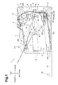
- Fig. 1 illustrates a general structure of an illustrative image forming apparatus, e.g. a laser printer, according to an embodiment of the disclosure
- Fig. 2 illustrates the laser printer with a top cover thereof being open, wherein a process cartridge is removed
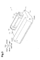
- Fig. 3 is a perspective view illustrating the process cartridge
- Fig. 4 illustrates a range in which a laser beam to be emitted from a scanner unit passes and positions of pressing portions
- Fig. 5 illustrates that, when the process cartridge is attached, a shaft of a photosensitive drum is guided by a first guide
- Fig. 6 illustrates that, when the process cartridge is attached, a boss is guided by an upper portion of a second guide
- Fig. 7 illustrates that, when the process cartridge is attached, the boss is guided by a lower portion of the second guide
- Fig. 8 illustrates that the process cartridge moves further toward an attachment position than that shown in Fig. 7 ;
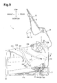
- Fig. 9 illustrates that the process cartridge is attached to the casing.
- Fig. 10 illustrates that the pressing portion contacts the process cartridge being attached.
- orientations or sides of the laser printer will be identified based on the laser printer disposed in an orientation in which it is intended to be used.
- the left side is referred to as the front or front side
- the right side is referred to as the rear or the rear side
- the up side is referred to as the top or upper side
- the down side is referred to as the bottom or lower side.
- the top and bottom direction may be referred to as a vertical direction.
- the laser printer 1 includes a main body 2, a feeder portion 3 for feeding a sheet P, and an image forming portion 4 for forming an image on the sheet P.
- the main body 2 includes a casing 21, a top cover 22 as an example of a cover, and a front cover 23.
- the casing 21 has an opening 21A ( Fig. 2 ), which is open upward, for attaching and removing a process cartridge 6 in an upper portion, and an insertion opening 21B for inserting sheets P in a front portion.
- the dimension of the opening 21A in the left-right direction is substantially equal to that of the process cartridge 6, and the dimension of the opening 21A in the front-rear direction is smaller than the dimension of the process cartridge 6 in a direction where a photosensitive drum 61 and a handle portion 113 are arranged.
- the top cover 22 is sized to cover the entire of the upper side of the casing 21 and is supported by the casing 21 such that the top cover 22 is configured to pivot about a pivot 22A disposed in a rear end portion of the casing 21. Thus, by being moved vertically, the top cover 22 is configured to open and close the opening 21A.
- An upper surface of the top cover 22 contains an ejection tray 9 on which a sheet P ejected by an ejection roller 8 outside the casing 21 is to be placed.
- the ejection tray 9 includes an extension cover 10.
- the extension cover 10 is supported by the top cover 22 such that the extension cover 10 is configured to pivot about a pivot shaft (not shown) disposed in a front end portion of the top cover 22.
- the extension cover 10 is configured to move between a position (indicated by a double dotted line) covering an upper surface of the ejection tray 9 and a position (indicated by a solid line) approximate to the ejection tray 9 supporting the leading end portion of a sheet P on the ejection tray 9.
- the front cover 23 is a cover covering a front surface of the casing 21 and is pivotally supported at its lower end portion by the casing 21. With this structure, by being pivoted in the front-rear direction, the front cover 23 is configured to open and close the insertion opening 21B of the casing 21.
- the feeder portion 3 is disposed in a lower portion of the main body 2, and includes a sheet tray 31 for placing a sheet P thereon and a sheet feed mechanism 32 that feeds a sheet P on the sheet tray 31 toward the image forming portion 4.
- the sheet tray 31 includes the front cover 23 and a sheet receiving plate 31A, which is disposed in a lower portion of the main body 2. Specifically, when tilted frontward, the front cover 23 constitutes a part of the sheet tray 31.
- the sheet receiving plate 31A is configured to raise a sheet P toward a feed roller 32A at timing when one sheet P is fed.
- the sheet feed mechanism 32 includes the feed roller 32A, a separation roller 32B, and a separation pad 32C.
- the feed roller 32A is disposed upstream of the separation roller 32B in a sheet conveying direction, and above the rear end of the sheet receiving plate 31A.
- the separation roller 32B is disposed facing the separation pad 32C.
- the front cover 23 is tilted down frontward to form the sheet tray 31, and a sheet P is placed on the sheet tray 31.
- the feed roller 32A rotates in contact with the sheet P placed on the sheet tray 31, and the sheet P placed on the sheet tray 31 is conveyed to the separation roller 32B, the fed sheet P is singly separated by the separation roller 32B and the separation pad 32C and conveyed to the image forming portion 4.
- the image forming portion 4 includes a scanner unit 5, a process cartridge 6, and a fixing unit 7.
- the scanner unit 5 is disposed above a front side of the feeder portion 3 in the main body 2, and includes a laser emitting portion, a polygon mirror, and a lens, which are not shown.
- the scanner unit 5 irradiates a surface of a photosensitive drum 61, as an example of a photosensitive member, with a laser beam at high speed scanning.
- the process cartridge 6 is disposed above a rear side of the feeder portion 3 in the main body 2, and is detachable through the opening 21A from the casing 21.
- the process cartridge 6 includes a photosensitive drum 61, a transfer roller 62 facing the photosensitive drum 61, an unnumbered charger, a developing roller 63, and a toner chamber, which is not shown.
- the surface of the photosensitive drum 61 which is rotating, is uniformly charged by the charger, and then exposed with the laser beam from the scanner unit 5 by high speed scanning. Thus, a potential in an exposed area drops, and an electrostatic latent image based on image data is formed on the surface of the photosensitive drum 61.
- the developing roller 63 supplies toner in the toner chamber to the electrostatic latent image formed on the photosensitive drum 61, and a toner image is formed on the surface of the photosensitive drum 61. Then, when a sheet P is fed in between the photosensitive drum 61 and the transfer roller 62, the toner image carried on the surface of the photosensitive drum 61 is transferred onto the sheet P.
- the fixing unit 7 is disposed above the process cartridge 6 in a rear side of the main body 2.
- the fixing unit 7 includes a heat roller 71 and a pressure roller 72.
- the heat roller 71 is a member that applies heat to a sheet P, and includes inside a heat source, e.g., a halogen lamp.
- the pressure roller 72 is a member that feeds a sheet P by sandwiching the sheet P with the heat roller 71, and is disposed diagonally upward from the rear side of the heat roller 71.
- the fixing unit 7 structured as described above is configured to fix toner transferred onto the sheet P thermally while the sheet P passes between the heat roller 71 and the pressure roller 72.
- the sheet P having the toner thermally fixed thereon is conveyed to the ejection roller 8, which is disposed downstream of the fixing unit 7, and ejected from the ejection roller 8 to the ejection tray 9.
- the process cartridge 6 rotatably supports, at its rear end portion, the photosensitive drum 61 and the transfer roller 62 ( Fig. 1 ).
- a front wall 112 disposed in a front end portion of the process cartridge 6 is provided with the handle portion 113 and pressed portions 114.
- Bosses 115 are disposed on the left and right side surfaces 111 of the process cartridge 6.
- the handle portion 113 is a portion held by a user during attachment or removal of the process cartridge 6, and is disposed in substantially a central portion of the process cartridge 6 in the left-right direction.
- the pressed portions 114 are portions which respective pressing portions 24 contact when the top cover 22 is closing the opening 21A.
- the pressed portions 114 are upper end surfaces of ribs protruding rearward from the front wall 112 with the handle portion 113 interposed therebetween.
- the bosses 115 are protrusions protruding outward from the left and right side surfaces 111 in the left-right direction.
- the bosses 115 are disposed in front end portions of the left and right side surfaces 111.
- the handle portion 113 is disposed closer to the bosses 115 than the shaft 61A of the photosensitive drum 61.
- the bosses 115 are disposed in upper end portions of front sides of the respective left and right side surfaces 111 and in positions where the bosses 115 overlap the pressed portions 114 in a direction where the shaft 61A and the bosses 115 are arranged and near the pressed portions 114.
- the process cartridge 6 structured as described above when attached to the casing 21, the process cartridge 6 structured as described above is disposed with its front end portion being lower than its rear end portion such that the handle portion 113 is disposed in a position lower than an exposure portion 61B of the photosensitive drum 61, which is to be exposed by the scanner unit 5.
- the scanner unit 5 is disposed in a position upper than the handle portion 113 such that laser light is not cut off by the handle portion 113.
- the scanner unit 5 is disposed in a lower position compared with a case where the handle portion 113 is disposed above the exposure portion 61B of the photosensitive drum 61, and thus the need to increase the physical size of the main body 2 can be obviated.
- the main body 2 includes a guide 200 disposed in the casing 21 and the pressing portions 24 disposed in the top cover 22 as a structure to attach and remove the process cartridge 6 with respect to the casing 21.
- the guide 200 is made up of a first guide 210 as an example of a further guide and a second guide 220 as an example of a particular guide, and is configured to guide the process cartridge 6 being attached or removed by guiding the shaft 61A of the photosensitive drum 61 by the first guide 210 and guiding the boss 115 by the second guide 220.
- the guide 200 is configured to hold the shaft 61A of the photosensitive drum 61 of the process cartridge 6 attached to the casing 21 and the boss 115 at their attachment positions ( Fig. 1 ).
- the first guide 210 is a groove formed in an inner surface of a side panel 21C disposed on each of the left and right sides of the casing 21.
- the first guide 210 is shaped to extend in an attaching direction where the process cartridge 6 is attached or diagonally downward from the opening 21A to the inside of the casing 21 such as to connect an upper end of the side panel 21C and the attachment position of the shaft 61A of the photosensitive drum 61.
- the second guide 220 is a groove formed in the inner surface of the side panel 21C of the casing 21 in front of the first guide 210.
- the second guide 220 is shaped to connect the attachment position of the boss 115 and the upper end of the side panel 21C.
- the second guide 220 has an upper portion 221 disposed on an upstream side in the attaching direction of the process cartridge 6 and a lower portion 222 disposed on a downstream side in the attaching direction of the process cartridge 6.
- the upper portion 221 extends from the upper end of the side panel 21C substantially straightly along the first guide 210.
- the lower portion 222 extends smoothly from a lower end of the upper portion 221 to the stop position of the boss 115, and is curved away from the first guide 210.
- the lower portion 222 extends in a direction crossing a direction where the upper portion 221 extends. In other words, the second guide 220 is bent at a portion where the upper portion 221 merges with the lower portion 222.
- the second guide 220 is longer in the vertical length than the first guide 210, and the lower end of the second guide 220 is located lower than the lower end of the first guide 210.
- the bent portion of the second guide 220 is disposed in a position closer to the upper end of the side panel 21C than the attachment position of the boss 115.
- the first guide 210 and the second guide 220 have such lengths that, during attaching of the process cartridge 6, the boss 115 is guided to its attachment position after the shaft 61A of the photosensitive drum 61 is guided to its attachment position.
- the pressing portions 24 are members that, when the top cover 22 closes the opening 21A, contact the pressed portions 114 of the process cartridge 6 being attached and press the process cartridge 6 into an attachment position in which the process cartridge 6 is attached to the casing 21.
- the pressing portions 24 are disposed on a surface of the top cover 22 opposite to the ejection tray 9 and protrude inside of the casing 21 from the top cover 22 when the top cover 22 closes the opening 21A. As shown in Fig. 4 , the pressing portions 24 are disposed one by one on the left and right sides to correspond the pressed portions 114 of the process cartridge 6. The pressing portions 24 are arranged such that laser light emitted from the scanner unit 5 passes between the pressing portions 24. In other words, the pressing portions 24 are disposed outside of a range where the laser light passes (or a range inside broken lines in Fig. 4 ).
- an end surface of the pressing portion 24 is a pressing surface 24A, as an example of a pressing portion, to contact the pressed portion 114 of the process cartridge 6.
- a path of the pressing surface 24A in the casing 21 while the top cover 22 is opened or closed is substantially same as the shape of the second guide 220.
- the path of the pressing surface 24A for a period of time from when the pressing surface 24A contacts the pressed portion 114 to when the process cartridge 6 moves to the attachment position is substantially same as the shape of the second guide 220 through which the boss 115 passes.
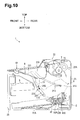
- the pressing surface 24A is shaped such as to, when contacting the pressed portion 114, face toward the attaching direction of the boss 115 such that a direction in which the pressing surface 24A presses the pressed portion 114 is substantially parallel to a direction in which the second guide 220 extends in proximity to the boss 115 ( Fig. 10 ).
- the user can close the top cover 22 while moving the process cartridge 6 to the attachment position lightly.
- the boss 115 is not pressed to the second guide 220 with a force that the pressing portion 24 presses the pressed portion 114.
- the process cartridge 6 is moved to the attachment position with a small force.
- the pressing portion 24 is disposed in such a position in the front-rear direction as to, when the pressing portion 24 contacts the pressed portion 114 of the process cartridge 6, overlap the second guide 220 in a radial direction of a circle centered on the pivot 22A (a pivot axis) of the top cover 22. In other words, the pressing portion 24 is disposed so as to overlap the second guide 220 as viewed from an axial direction of the pivot 22A.
- This positional relationship reduces the potential of the process cartridge 6 from being twisted when being pressed by the pressing portion 24, compared with a case where the pressing portion 24 is disposed in a position away from the second guide 220 in the radial direction of the circle centered on the pivot 22A of the top cover 22.
- a user opens the top cover 22, holds the handle portion 113, and brings the process cartridge 6 close to the casing 21 from the photosensitive drum 61 side. As shown in Fig. 5 , the user inserts the shaft 61A of the photosensitive drum 61 into the first guide 210 to move the process cartridge 6 into the casing 21 along the first guide 210.
- the boss 115 is inserted into the upper portion 221 of the second guide 220.
- a portion of the second guide 220 that guides the boss 115 changes from the upper portion 221 to the lower portion 222.
- the boss 115 is guide by the lower portion 222 to move toward the attachment position.
- the lower portion 222 allows the process cartridge 6 to move smoothly because the lower portion 222 has a smooth curved shape to the attachment position of the boss 115.
- the boss 115 stops at the end of the lower portion 222 of the second guide 220 so that the process cartridge 6 is attached to the casing 21 as shown in Fig. 9 .
- the pressing portion 24 contacts the pressed portion 114 of the process cartridge 6 located short of the attachment position, and presses the process cartridge 6 into the attachment position.
- the pressing portion 24 allows the process cartridge 6 to be attached in position.
- the user opens the top cover 22, holds the handle portion 113 of the process cartridge 6, and pulls the process cartridge 6 toward the user.
- the shaft 61A of the photosensitive drum 61 is guided by the first guide 210
- the boss 115 is guided by the second guide 220
- the process cartridge 6 moves outward in the casing 21.
- the lower portion 222 has a smooth curved shape from the attachment position of the boss 115 to the upper portion 221, a moving direction of the process cartridge 6 is not greatly changed in the vicinity of the attachment position of the boss 115.
- the process cartridge 6 can be pulled out smoothly.
- the attaching direction of the process cartridge 6 agrees with the direction where the pressing surface 24A presses the process cartridge 6.
- the user can close the top cover while moving the process cartridge 6 to the attachment position lightly.
- the direction where the pressing surface 24A presses the process cartridge 6 is substantially parallel to the direction where the second guide 220 extends in the vicinity of the boss 115.
- the boss 115 is not pressed against the second guide 220.
- the user can press the top cover 22 lightly to close the top cover 22.
- the pressing surface 24A When contacting the process cartridge 6, the pressing surface 24A is disposed in the position where it overlaps the second guide 220 in the radial direction of a circle centered on the pivot 22A of the top cover 22.
- the process cartridge 6 can be prevented from being twisted when being pressed by the pressing surface 24A.
- the pressed portions 114 are disposed at the upper end portion of the entire process cartridge 6, and the bosses 115 are disposed at the upper end portion of the side surfaces 111 of the process cartridge 6. Thus, the pressed portions 114 and the bosses 115 are disposed near each other.
- the moving direction of the bosses 115 is similar to the direction where the pressing surface 24A presses.
- the pressing surface 24A is disposed in the position where it overlaps the second guide 220 in the radial direction of a circle centered on the pivot 22A of the top cover 22.
- the pressing surface 24A may be disposed in a position shifted from the second guide 220 in the radial direction of a circle centered on the pivot 22A when the pressing surface 24A contacts the pressed portions 114 of the process cartridge 6.
- the above embodiment shows, but is not limited to the pressing surface 24A which is flat and formed at a distal end of the pressing portion 24.
- the pressing portion 24 may have a round distal end which is to contact the pressed portions 114 of the process cartridge 6.
- a point of the distal end of the pressing portion 24 that contacts the pressed portion 114 is a pressing portion.
- the above embodiment shows, but is not limited to, that the photosensitive drum 61 is illustrated as the photosensitive member.
- a belt-shaped photosensitive member may be used.
Abstract
Description
- Aspects of the disclosure relate to an image forming apparatus including a casing and a process cartridge detachably attachable to the casing.
- A known image forming apparatus includes a process cartridge detachably attachable to a main body of the image forming apparatus by being guided by a guide provided in the main body, as disclosed in, for example, Japanese Laid-Open Patent Publication No.
2011-227457 - In the image forming apparatus, the cover includes a pressing portion configured to press the process cartridge being attached toward an attachment position when the cover closes the opening. The pressing portion is configured to contact a horizontal surface of the process cartridge and press the horizontal surface vertically.
- However, in the above-described art, a direction in which the guide extends is different from a direction in which the pressing portion presses the process cartridge, and thus the user needs to press the cover strongly when closing it.
- Illustrative aspects of the disclosure provide an image forming apparatus configured such that a cover is closed lightly while a process cartridge is moved to its attachment position.
- According to an aspect of the disclosure, an image forming apparatus includes a casing having an opening that is open upward, a cover supported by the casing, a process cartridge configured to be attached to or removed from the casing through the opening, and a particular guide configured to guide the process cartridge when the process cartridge is attached to or removed from the casing. The cover is configured to pivot around a pivot axis to open and close the opening. The cover includes a pressing portion. The pressing portion is configured to, when the cover is closing the opening, contact the process cartridge being attached inside the casing and press the process cartridge toward an attachment position in which the process cartridge is attached to the casing. A path of the pressing portion in the casing, while the cover pivots, is substantially same as a shape of the particular guide as viewed from an axial direction of the pivot axis.
- According to the image forming apparatus configured above, a direction in which the process cartridge is attached agrees with a direction in which the pressing portion presses the process cartridge, and thus the cover can be closed lightly while the process cartridge can be moved to its attachment position.
- Illustrative aspects will be described in detail with reference to the following figures in which like elements are labeled with like numbers and in which:
-
Fig. 1 illustrates a general structure of an illustrative image forming apparatus, e.g. a laser printer, according to an embodiment of the disclosure; -
Fig. 2 illustrates the laser printer with a top cover thereof being open, wherein a process cartridge is removed; -
Fig. 3 is a perspective view illustrating the process cartridge; -
Fig. 4 illustrates a range in which a laser beam to be emitted from a scanner unit passes and positions of pressing portions; -
Fig. 5 illustrates that, when the process cartridge is attached, a shaft of a photosensitive drum is guided by a first guide; -
Fig. 6 illustrates that, when the process cartridge is attached, a boss is guided by an upper portion of a second guide; -
Fig. 7 illustrates that, when the process cartridge is attached, the boss is guided by a lower portion of the second guide; -
Fig. 8 illustrates that the process cartridge moves further toward an attachment position than that shown inFig. 7 ; -
Fig. 9 illustrates that the process cartridge is attached to the casing; and -
Fig. 10 illustrates that the pressing portion contacts the process cartridge being attached. - A first illustrative embodiment will be described in detail with reference to the accompanying drawings. In the following description, a general structure of a laser printer, as an example of an image forming apparatus, will be described and then features of the disclosure will be described in detail.
- In the following description, orientations or sides of the laser printer will be identified based on the laser printer disposed in an orientation in which it is intended to be used. In other words, in
Fig. 1 , the left side is referred to as the front or front side, the right side is referred to as the rear or the rear side, the up side is referred to as the top or upper side, and the down side is referred to as the bottom or lower side. The top and bottom direction may be referred to as a vertical direction. - As shown in
Fig. 1 , thelaser printer 1 includes amain body 2, afeeder portion 3 for feeding a sheet P, and animage forming portion 4 for forming an image on the sheet P. - The
main body 2 includes acasing 21, atop cover 22 as an example of a cover, and afront cover 23. Thecasing 21 has an opening 21A (Fig. 2 ), which is open upward, for attaching and removing aprocess cartridge 6 in an upper portion, and an insertion opening 21B for inserting sheets P in a front portion. - Specifically, the dimension of the opening 21A in the left-right direction is substantially equal to that of the
process cartridge 6, and the dimension of the opening 21A in the front-rear direction is smaller than the dimension of theprocess cartridge 6 in a direction where aphotosensitive drum 61 and ahandle portion 113 are arranged. - The
top cover 22 is sized to cover the entire of the upper side of thecasing 21 and is supported by thecasing 21 such that thetop cover 22 is configured to pivot about apivot 22A disposed in a rear end portion of thecasing 21. Thus, by being moved vertically, thetop cover 22 is configured to open and close the opening 21A. - An upper surface of the
top cover 22 contains anejection tray 9 on which a sheet P ejected by anejection roller 8 outside thecasing 21 is to be placed. Theejection tray 9 includes anextension cover 10. Theextension cover 10 is supported by thetop cover 22 such that theextension cover 10 is configured to pivot about a pivot shaft (not shown) disposed in a front end portion of thetop cover 22. Theextension cover 10 is configured to move between a position (indicated by a double dotted line) covering an upper surface of theejection tray 9 and a position (indicated by a solid line) approximate to theejection tray 9 supporting the leading end portion of a sheet P on theejection tray 9. - The
front cover 23 is a cover covering a front surface of thecasing 21 and is pivotally supported at its lower end portion by thecasing 21. With this structure, by being pivoted in the front-rear direction, thefront cover 23 is configured to open and close the insertion opening 21B of thecasing 21. - The
feeder portion 3 is disposed in a lower portion of themain body 2, and includes asheet tray 31 for placing a sheet P thereon and asheet feed mechanism 32 that feeds a sheet P on thesheet tray 31 toward theimage forming portion 4. - The
sheet tray 31 includes thefront cover 23 and asheet receiving plate 31A, which is disposed in a lower portion of themain body 2. Specifically, when tilted frontward, thefront cover 23 constitutes a part of thesheet tray 31. Thesheet receiving plate 31A is configured to raise a sheet P toward afeed roller 32A at timing when one sheet P is fed. - The
sheet feed mechanism 32 includes thefeed roller 32A, aseparation roller 32B, and aseparation pad 32C. Thefeed roller 32A is disposed upstream of theseparation roller 32B in a sheet conveying direction, and above the rear end of thesheet receiving plate 31A. Theseparation roller 32B is disposed facing theseparation pad 32C. - In the
feeder portion 3, thefront cover 23 is tilted down frontward to form thesheet tray 31, and a sheet P is placed on thesheet tray 31. Thefeed roller 32A rotates in contact with the sheet P placed on thesheet tray 31, and the sheet P placed on thesheet tray 31 is conveyed to theseparation roller 32B, the fed sheet P is singly separated by theseparation roller 32B and theseparation pad 32C and conveyed to theimage forming portion 4. - The
image forming portion 4 includes ascanner unit 5, aprocess cartridge 6, and afixing unit 7. - The
scanner unit 5 is disposed above a front side of thefeeder portion 3 in themain body 2, and includes a laser emitting portion, a polygon mirror, and a lens, which are not shown. Thescanner unit 5 irradiates a surface of aphotosensitive drum 61, as an example of a photosensitive member, with a laser beam at high speed scanning. - The
process cartridge 6 is disposed above a rear side of thefeeder portion 3 in themain body 2, and is detachable through the opening 21A from thecasing 21. Theprocess cartridge 6 includes aphotosensitive drum 61, atransfer roller 62 facing thephotosensitive drum 61, an unnumbered charger, a developingroller 63, and a toner chamber, which is not shown. - In the
process cartridge 6, the surface of thephotosensitive drum 61, which is rotating, is uniformly charged by the charger, and then exposed with the laser beam from thescanner unit 5 by high speed scanning. Thus, a potential in an exposed area drops, and an electrostatic latent image based on image data is formed on the surface of thephotosensitive drum 61. - The developing
roller 63 supplies toner in the toner chamber to the electrostatic latent image formed on thephotosensitive drum 61, and a toner image is formed on the surface of thephotosensitive drum 61. Then, when a sheet P is fed in between thephotosensitive drum 61 and thetransfer roller 62, the toner image carried on the surface of thephotosensitive drum 61 is transferred onto the sheet P. - The fixing
unit 7 is disposed above theprocess cartridge 6 in a rear side of themain body 2. The fixingunit 7 includes aheat roller 71 and apressure roller 72. - The
heat roller 71 is a member that applies heat to a sheet P, and includes inside a heat source, e.g., a halogen lamp. - The
pressure roller 72 is a member that feeds a sheet P by sandwiching the sheet P with theheat roller 71, and is disposed diagonally upward from the rear side of theheat roller 71. - The fixing
unit 7 structured as described above is configured to fix toner transferred onto the sheet P thermally while the sheet P passes between theheat roller 71 and thepressure roller 72. The sheet P having the toner thermally fixed thereon is conveyed to theejection roller 8, which is disposed downstream of the fixingunit 7, and ejected from theejection roller 8 to theejection tray 9. - The following will describe the structure around the
process cartridge 6, which is a feature of the disclosure. - As shown in
Fig. 3 , theprocess cartridge 6 rotatably supports, at its rear end portion, thephotosensitive drum 61 and the transfer roller 62 (Fig. 1 ). Ashaft 61A, as an example of a further guided portion, of thephotosensitive drum 61, which is supported by theprocess cartridge 6, extends outside left and right side surfaces 111 of theprocess cartridge 6. - A
front wall 112 disposed in a front end portion of theprocess cartridge 6 is provided with thehandle portion 113 and pressedportions 114.Bosses 115, as an example of a particular guided portion, are disposed on the left and right side surfaces 111 of theprocess cartridge 6. - The
handle portion 113 is a portion held by a user during attachment or removal of theprocess cartridge 6, and is disposed in substantially a central portion of theprocess cartridge 6 in the left-right direction. - The pressed
portions 114 are portions which respectivepressing portions 24 contact when thetop cover 22 is closing theopening 21A. The pressedportions 114 are upper end surfaces of ribs protruding rearward from thefront wall 112 with thehandle portion 113 interposed therebetween. - The
bosses 115 are protrusions protruding outward from the left and right side surfaces 111 in the left-right direction. Thebosses 115 are disposed in front end portions of the left and right side surfaces 111. Thehandle portion 113 is disposed closer to thebosses 115 than theshaft 61A of thephotosensitive drum 61. Thebosses 115 are disposed in upper end portions of front sides of the respective left and right side surfaces 111 and in positions where thebosses 115 overlap the pressedportions 114 in a direction where theshaft 61A and thebosses 115 are arranged and near the pressedportions 114. - As shown in
Fig. 1 , when attached to thecasing 21, theprocess cartridge 6 structured as described above is disposed with its front end portion being lower than its rear end portion such that thehandle portion 113 is disposed in a position lower than anexposure portion 61B of thephotosensitive drum 61, which is to be exposed by thescanner unit 5. Thescanner unit 5 is disposed in a position upper than thehandle portion 113 such that laser light is not cut off by thehandle portion 113. By disposing theprocess cartridge 6 as described above, thescanner unit 5 is disposed in a lower position compared with a case where thehandle portion 113 is disposed above theexposure portion 61B of thephotosensitive drum 61, and thus the need to increase the physical size of themain body 2 can be obviated. - As shown in
Fig. 2 , themain body 2 includes aguide 200 disposed in thecasing 21 and thepressing portions 24 disposed in thetop cover 22 as a structure to attach and remove theprocess cartridge 6 with respect to thecasing 21. - The
guide 200 is made up of afirst guide 210 as an example of a further guide and asecond guide 220 as an example of a particular guide, and is configured to guide theprocess cartridge 6 being attached or removed by guiding theshaft 61A of thephotosensitive drum 61 by thefirst guide 210 and guiding theboss 115 by thesecond guide 220. - In a state that the
process cartridge 6 is attached to thecasing 21, the lower end of thefirst guide 210 supports theshaft 61A of thephotosensitive drum 61, and the lower end of thesecond guide 220 supports thecorresponding boss 115. Thus, theguide 200 is configured to hold theshaft 61A of thephotosensitive drum 61 of theprocess cartridge 6 attached to thecasing 21 and theboss 115 at their attachment positions (Fig. 1 ). - Specifically, the
first guide 210 is a groove formed in an inner surface of aside panel 21C disposed on each of the left and right sides of thecasing 21. Thefirst guide 210 is shaped to extend in an attaching direction where theprocess cartridge 6 is attached or diagonally downward from theopening 21A to the inside of thecasing 21 such as to connect an upper end of theside panel 21C and the attachment position of theshaft 61A of thephotosensitive drum 61. - The
second guide 220 is a groove formed in the inner surface of theside panel 21C of thecasing 21 in front of thefirst guide 210. Thesecond guide 220 is shaped to connect the attachment position of theboss 115 and the upper end of theside panel 21C. Thesecond guide 220 has anupper portion 221 disposed on an upstream side in the attaching direction of theprocess cartridge 6 and alower portion 222 disposed on a downstream side in the attaching direction of theprocess cartridge 6. - The
upper portion 221 extends from the upper end of theside panel 21C substantially straightly along thefirst guide 210. Thelower portion 222 extends smoothly from a lower end of theupper portion 221 to the stop position of theboss 115, and is curved away from thefirst guide 210. Thelower portion 222 extends in a direction crossing a direction where theupper portion 221 extends. In other words, thesecond guide 220 is bent at a portion where theupper portion 221 merges with thelower portion 222. - The
second guide 220 is longer in the vertical length than thefirst guide 210, and the lower end of thesecond guide 220 is located lower than the lower end of thefirst guide 210. The bent portion of thesecond guide 220 is disposed in a position closer to the upper end of theside panel 21C than the attachment position of theboss 115. Thefirst guide 210 and thesecond guide 220 have such lengths that, during attaching of theprocess cartridge 6, theboss 115 is guided to its attachment position after theshaft 61A of thephotosensitive drum 61 is guided to its attachment position. - The
pressing portions 24 are members that, when thetop cover 22 closes theopening 21A, contact the pressedportions 114 of theprocess cartridge 6 being attached and press theprocess cartridge 6 into an attachment position in which theprocess cartridge 6 is attached to thecasing 21. - Specifically, the
pressing portions 24 are disposed on a surface of thetop cover 22 opposite to theejection tray 9 and protrude inside of thecasing 21 from thetop cover 22 when thetop cover 22 closes theopening 21A. As shown inFig. 4 , thepressing portions 24 are disposed one by one on the left and right sides to correspond the pressedportions 114 of theprocess cartridge 6. Thepressing portions 24 are arranged such that laser light emitted from thescanner unit 5 passes between thepressing portions 24. In other words, thepressing portions 24 are disposed outside of a range where the laser light passes (or a range inside broken lines inFig. 4 ). - As shown in
Fig. 2 , an end surface of thepressing portion 24 is apressing surface 24A, as an example of a pressing portion, to contact the pressedportion 114 of theprocess cartridge 6. A path of thepressing surface 24A in thecasing 21 while thetop cover 22 is opened or closed (indicated by an alternate long and short dashed line) is substantially same as the shape of thesecond guide 220. Specifically, in the course of closing thetop cover 22, the path of thepressing surface 24A for a period of time from when thepressing surface 24A contacts the pressedportion 114 to when theprocess cartridge 6 moves to the attachment position is substantially same as the shape of thesecond guide 220 through which theboss 115 passes. Thepressing surface 24A is shaped such as to, when contacting the pressedportion 114, face toward the attaching direction of theboss 115 such that a direction in which thepressing surface 24A presses the pressedportion 114 is substantially parallel to a direction in which thesecond guide 220 extends in proximity to the boss 115 (Fig. 10 ). - As the attaching direction of the
process cartridge 6 agrees with the direction where thepressing surface 24A presses the pressedportion 114, the user can close thetop cover 22 while moving theprocess cartridge 6 to the attachment position lightly. - With this structure, the
boss 115 is not pressed to thesecond guide 220 with a force that thepressing portion 24 presses the pressedportion 114. When the user closes thetop cover 22, theprocess cartridge 6 is moved to the attachment position with a small force. - The
pressing portion 24 is disposed in such a position in the front-rear direction as to, when thepressing portion 24 contacts the pressedportion 114 of theprocess cartridge 6, overlap thesecond guide 220 in a radial direction of a circle centered on thepivot 22A (a pivot axis) of thetop cover 22. In other words, thepressing portion 24 is disposed so as to overlap thesecond guide 220 as viewed from an axial direction of thepivot 22A. - This positional relationship reduces the potential of the
process cartridge 6 from being twisted when being pressed by thepressing portion 24, compared with a case where thepressing portion 24 is disposed in a position away from thesecond guide 220 in the radial direction of the circle centered on thepivot 22A of thetop cover 22. - The following will describe how the
process cartridge 6 is attached to or removed from thecasing 21. - In case of attaching the
process cartridge 6 to thecasing 21, a user opens thetop cover 22, holds thehandle portion 113, and brings theprocess cartridge 6 close to thecasing 21 from thephotosensitive drum 61 side. As shown inFig. 5 , the user inserts theshaft 61A of thephotosensitive drum 61 into thefirst guide 210 to move theprocess cartridge 6 into thecasing 21 along thefirst guide 210. - As shown in
Fig. 6 , as theprocess cartridge 6 is guided by thefirst guide 210 to move into thecasing 21, theboss 115 is inserted into theupper portion 221 of thesecond guide 220. As shown inFig. 7 , as theprocess cartridge 6 is pressed further inward, a portion of thesecond guide 220 that guides theboss 115 changes from theupper portion 221 to thelower portion 222. Thus, as shown inFig. 8 , theboss 115 is guide by thelower portion 222 to move toward the attachment position. At this time, thelower portion 222 allows theprocess cartridge 6 to move smoothly because thelower portion 222 has a smooth curved shape to the attachment position of theboss 115. - After the
shaft 61A of thephotosensitive drum 61 stops at the end of thefirst guide 210, theboss 115 stops at the end of thelower portion 222 of thesecond guide 220 so that theprocess cartridge 6 is attached to thecasing 21 as shown inFig. 9 . - As shown in
Fig. 10 , in a state that the user did not move theprocess cartridge 6 completely to the attachment position and thus theprocess cartridge 6 stops short of the attachment position, when thetop cover 22 is closed, thepressing portion 24 contacts the pressedportion 114 of theprocess cartridge 6 located short of the attachment position, and presses theprocess cartridge 6 into the attachment position. Thus, even when thetop cover 22 is closed with theprocess cartridge 6 not attached in position, thepressing portion 24 allows theprocess cartridge 6 to be attached in position. - In case of removing the
process cartridge 6 from thecasing 21, the user opens thetop cover 22, holds thehandle portion 113 of theprocess cartridge 6, and pulls theprocess cartridge 6 toward the user. At this time, theshaft 61A of thephotosensitive drum 61 is guided by thefirst guide 210, theboss 115 is guided by thesecond guide 220, and theprocess cartridge 6 moves outward in thecasing 21. At this time, as thelower portion 222 has a smooth curved shape from the attachment position of theboss 115 to theupper portion 221, a moving direction of theprocess cartridge 6 is not greatly changed in the vicinity of the attachment position of theboss 115. Thus, theprocess cartridge 6 can be pulled out smoothly. - According to the embodiment, the following effects can be obtained.
- As the path of the
pressing surface 24A in thecasing 21 while thetop cover 22 is opened or closed is substantially same as the shape of thesecond guide 220, the attaching direction of theprocess cartridge 6 agrees with the direction where thepressing surface 24A presses theprocess cartridge 6. Thus, the user can close the top cover while moving theprocess cartridge 6 to the attachment position lightly. - The direction where the
pressing surface 24A presses theprocess cartridge 6 is substantially parallel to the direction where thesecond guide 220 extends in the vicinity of theboss 115. When theprocess cartridge 6 is pressed by thepressing surface 24A, theboss 115 is not pressed against thesecond guide 220. As there is little resistance from thesecond guide 220, the user can press thetop cover 22 lightly to close thetop cover 22. - When contacting the
process cartridge 6, thepressing surface 24A is disposed in the position where it overlaps thesecond guide 220 in the radial direction of a circle centered on thepivot 22A of thetop cover 22. Thus, compared with a case where thepressing surface 24A is disposed in a position away from thesecond guide 220, theprocess cartridge 6 can be prevented from being twisted when being pressed by thepressing surface 24A. - The pressed
portions 114 are disposed at the upper end portion of theentire process cartridge 6, and thebosses 115 are disposed at the upper end portion of the side surfaces 111 of theprocess cartridge 6. Thus, the pressedportions 114 and thebosses 115 are disposed near each other. The moving direction of thebosses 115 is similar to the direction where thepressing surface 24A presses. - The above embodiment shows, but is not limited to, that the
pressing surface 24A is disposed in the position where it overlaps thesecond guide 220 in the radial direction of a circle centered on thepivot 22A of thetop cover 22. For example, thepressing surface 24A may be disposed in a position shifted from thesecond guide 220 in the radial direction of a circle centered on thepivot 22A when thepressing surface 24A contacts the pressedportions 114 of theprocess cartridge 6. - The above embodiment shows, but is not limited to the
pressing surface 24A which is flat and formed at a distal end of thepressing portion 24. For example, thepressing portion 24 may have a round distal end which is to contact the pressedportions 114 of theprocess cartridge 6. In this case, a point of the distal end of thepressing portion 24 that contacts the pressedportion 114 is a pressing portion. - The above embodiment shows, but is not limited to, that the
photosensitive drum 61 is illustrated as the photosensitive member. A belt-shaped photosensitive member may be used. - While the features herein have been described in connection with various example structures and illustrative aspects, it will be understood by those skilled in the art that other variations and modifications of the structures and aspects described above may be made without departing from the scope of the inventions described herein. Other structures and aspects will be apparent to those skilled in the art from a consideration of the specification or practice of the features disclosed herein. It is intended that the specification and the described examples only are illustrative with the true scope of the inventions being defined by the following claims.
Claims (10)
- An image forming apparatus (1) comprising:a casing (21) having an opening (21A) that is open upward;a cover (22) supported by the casing such that the cover is configured to pivot around a pivot axis to open and close the opening, the cover including a pressing portion (24A);a process cartridge (6) configured to be attached to or removed from the casing through the opening; anda particular guide (220) configured to guide the process cartridge when the process cartridge is attached to or removed from the casing,wherein the pressing portion is configured to, when the cover is closing the opening, contact the process cartridge being attached inside the casing and press the process cartridge toward an attachment position in which the process cartridge is attached to the casing, andwherein a path of the pressing portion in the casing, while the cover pivots, is substantially same as a shape of the particular guide as viewed from an axial direction of the pivot axis.
- The image forming apparatus according to claim 1, wherein the process cartridge includes a particular guided portion (115) to be guided by the particular guide, and a direction where the pressing portion presses the process cartridge is substantially parallel to a direction where the particular guide extends in proximity to the particular guided portion.
- The image forming apparatus according to claim 2, wherein the particular guided portion of the process cartridge to be pressed by the pressing portion is disposed in an upper end portion of a whole of the process cartridge, and the particular guided portion is disposed in an upper end portion of a side surface of the process cartridge.
- The image forming apparatus according to claim 2 or 3, further comprising a further guide (210).
- The image forming apparatus according to claim 4, wherein the process cartridge further includes a photosensitive member (61) and a further guided portion (61A) disposed closer to the photosensitive member than the particular guided portion, and
wherein the further guide is configured to guide the further guided portion of the process cartridge when the process cartridge is attached to or removed from the casing. - The image forming apparatus according to claim 5, wherein the particular guide and the further guide are shaped such that, during attaching of the process cartridge, the particular guided portion is guided to a downstream end of the particular guide after the further guided portion is guided to a downstream end of the further guide.
- The image forming apparatus according to claim 6, wherein the further guide is shaped such that a downstream side of the further guide in an attaching direction of the process cartridge is gradually away from the path of the pressing portion.
- The image forming apparatus according to any preceding claim, wherein the pressing portion is disposed in such a position that, when the pressing portion contacts the process cartridge, the pressing portion overlaps the particular guide as viewed from the axial direction of the pivot axis.
- The image forming apparatus according to claim 8, further comprising a further guide (210),
wherein the further guide is shaped such that a downstream side of the further guide in an attaching direction of the process cartridge is closer to the pivot axis of the cover than a downstream side of the particular guide is. - The image forming apparatus according to any preceding claim, wherein the path of the pressing portion and the shape of the particular guide are arc shaped.
Applications Claiming Priority (1)
| Application Number | Priority Date | Filing Date | Title |
|---|---|---|---|
| JP2012081545A JP5928879B2 (en) | 2012-03-30 | 2012-03-30 | Image forming apparatus |
Publications (3)
| Publication Number | Publication Date |
|---|---|
| EP2645181A2 true EP2645181A2 (en) | 2013-10-02 |
| EP2645181A3 EP2645181A3 (en) | 2017-11-08 |
| EP2645181B1 EP2645181B1 (en) | 2021-08-11 |
Family
ID=47997025
Family Applications (1)
| Application Number | Title | Priority Date | Filing Date |
|---|---|---|---|
| EP13159590.2A Active EP2645181B1 (en) | 2012-03-30 | 2013-03-15 | Image forming apparatus |
Country Status (4)
| Country | Link |
|---|---|
| US (1) | US9075389B2 (en) |
| EP (1) | EP2645181B1 (en) |
| JP (1) | JP5928879B2 (en) |
| CN (1) | CN103365191B (en) |
Families Citing this family (11)
| Publication number | Priority date | Publication date | Assignee | Title |
|---|---|---|---|---|
| JP5445028B2 (en) * | 2009-10-23 | 2014-03-19 | セイコーエプソン株式会社 | Platen support mechanism and roll paper printer |
| US9274498B2 (en) * | 2013-08-13 | 2016-03-01 | Brother Kogyo Kabushiki Kaisha | Process unit and exposure unit arrangement in an image forming apparatus |
| JP6137026B2 (en) * | 2014-03-31 | 2017-05-31 | ブラザー工業株式会社 | Image forming apparatus |
| JP6281380B2 (en) * | 2014-03-31 | 2018-02-21 | ブラザー工業株式会社 | Image forming apparatus |
| JP6281379B2 (en) * | 2014-03-31 | 2018-02-21 | ブラザー工業株式会社 | Image forming apparatus |
| JP6379585B2 (en) | 2014-03-31 | 2018-08-29 | ブラザー工業株式会社 | Image forming apparatus |
| JP6618167B2 (en) | 2014-10-31 | 2019-12-11 | ブラザー工業株式会社 | Image forming apparatus |
| JP2017132582A (en) * | 2016-01-27 | 2017-08-03 | シャープ株式会社 | Sheet supply device and image formation device equipped with the same |
| CN105954988B (en) * | 2016-07-15 | 2019-11-08 | 深圳超俊科技有限公司 | A kind of location structure of toner cartridge |
| US10444665B2 (en) * | 2017-10-03 | 2019-10-15 | Canon Kabushiki Kaisha | Image forming apparatus |
| JP7254529B2 (en) * | 2019-01-15 | 2023-04-10 | キヤノン株式会社 | Process cartridge and image forming apparatus |
Citations (1)
| Publication number | Priority date | Publication date | Assignee | Title |
|---|---|---|---|---|
| JP2011227457A (en) | 2010-03-31 | 2011-11-10 | Canon Inc | Image forming apparatus |
Family Cites Families (25)
| Publication number | Priority date | Publication date | Assignee | Title |
|---|---|---|---|---|
| DE69219915T2 (en) * | 1991-01-25 | 1997-11-20 | Canon Kk | Electrophotographic imaging device with a mounting assembly for the work unit |
| DE4305686C2 (en) | 1992-02-24 | 1999-07-15 | Fujitsu Ltd | Toner image transfer device including a transfer charger and an AC charge eraser |
| JPH06314001A (en) | 1993-04-28 | 1994-11-08 | Canon Inc | Gear unit and image forming device |
| JP3382399B2 (en) | 1994-12-26 | 2003-03-04 | キヤノン株式会社 | Process cartridge and image forming apparatus |
| JPH0916056A (en) * | 1995-06-30 | 1997-01-17 | Canon Inc | Process cartridge and image forming device |
| JP3342362B2 (en) * | 1996-09-20 | 2002-11-05 | キヤノン株式会社 | Process cartridge and electrophotographic image forming apparatus |
| JP3672067B2 (en) * | 1998-01-20 | 2005-07-13 | 株式会社リコー | Image forming apparatus |
| JP2000131943A (en) * | 1998-10-21 | 2000-05-12 | Canon Inc | Developing unit, process cartridge and electrophotographic image forming device |
| JP2000250310A (en) | 1999-02-26 | 2000-09-14 | Brother Ind Ltd | Image forming device, photoreceptor cartridge, and developing cartridge |
| JP3347686B2 (en) * | 1999-04-02 | 2002-11-20 | キヤノン株式会社 | Electrophotographic image forming apparatus and process cartridge pushing mechanism |
| JP2002278415A (en) * | 2001-03-16 | 2002-09-27 | Canon Inc | Process cartridge and electrophotographic image forming device |
| US6751428B2 (en) | 2001-09-13 | 2004-06-15 | Brother Kogyo Kabushiki Kaisha | Image forming device and detachably loaded process unit |
| JP4474178B2 (en) | 2004-02-27 | 2010-06-02 | キヤノン株式会社 | Image forming apparatus |
| JP4524624B2 (en) | 2005-01-20 | 2010-08-18 | ブラザー工業株式会社 | Setup program and image forming system |
| JP2007163880A (en) * | 2005-12-14 | 2007-06-28 | Canon Inc | Image forming apparatus |
| JP2007163879A (en) * | 2005-12-14 | 2007-06-28 | Canon Inc | Noise reduction mechanism of image forming apparatus |
| JP4701313B2 (en) | 2006-12-13 | 2011-06-15 | キヤノン株式会社 | Electrophotographic image forming apparatus |
| JP4667444B2 (en) | 2006-12-13 | 2011-04-13 | キヤノン株式会社 | Electrophotographic image forming apparatus |
| JP2008158381A (en) * | 2006-12-26 | 2008-07-10 | Brother Ind Ltd | Image forming apparatus |
| JP5049615B2 (en) | 2007-03-09 | 2012-10-17 | キヤノン株式会社 | Electrophotographic image forming apparatus |
| JP4438841B2 (en) | 2007-08-31 | 2010-03-24 | ブラザー工業株式会社 | Image forming apparatus and process cartridge |
| JP4721464B2 (en) | 2008-04-25 | 2011-07-13 | キヤノン株式会社 | Electrophotographic image forming apparatus |
| US8515309B2 (en) | 2009-12-25 | 2013-08-20 | Brother Kogyo Kabushiki Kaisha | Process cartridge, developing cartridge and image forming apparatus |
| JP5284341B2 (en) | 2010-01-14 | 2013-09-11 | キヤノン株式会社 | Image forming apparatus |
| JP5787612B2 (en) | 2010-06-22 | 2015-09-30 | キヤノン株式会社 | Image forming apparatus |
-
2012
- 2012-03-30 JP JP2012081545A patent/JP5928879B2/en active Active
-
2013
- 2013-03-15 CN CN201310091199.9A patent/CN103365191B/en active Active
- 2013-03-15 US US13/834,104 patent/US9075389B2/en active Active
- 2013-03-15 EP EP13159590.2A patent/EP2645181B1/en active Active
Patent Citations (1)
| Publication number | Priority date | Publication date | Assignee | Title |
|---|---|---|---|---|
| JP2011227457A (en) | 2010-03-31 | 2011-11-10 | Canon Inc | Image forming apparatus |
Also Published As
| Publication number | Publication date |
|---|---|
| JP5928879B2 (en) | 2016-06-01 |
| CN103365191A (en) | 2013-10-23 |
| US20130259518A1 (en) | 2013-10-03 |
| EP2645181B1 (en) | 2021-08-11 |
| US9075389B2 (en) | 2015-07-07 |
| CN103365191B (en) | 2017-05-10 |
| JP2013210539A (en) | 2013-10-10 |
| EP2645181A3 (en) | 2017-11-08 |
Similar Documents
| Publication | Publication Date | Title |
|---|---|---|
| US9075389B2 (en) | Image forming apparatus with pressing portion and guide | |
| EP2645182B1 (en) | Image forming apparatus | |
| US9340378B2 (en) | Image forming apparatus | |
| US10831149B2 (en) | Image forming apparatus having mountable and demountable photosensitive member cartridge and developing cartridge | |
| US9280132B2 (en) | Image forming apparatus including pivotable process cartridge | |
| US8939446B2 (en) | Roller device | |
| US11815847B2 (en) | Image forming apparatus | |
| EP2338815A2 (en) | Sheet feed device | |
| JP2014015315A (en) | Sheet conveyance apparatus and image forming apparatus | |
| US9389579B2 (en) | Image forming apparatus having a removable mounted developing cartridge | |
| US9429893B2 (en) | Movable tray cover configuration for an image forming apparatus | |
| US20130322894A1 (en) | Image Forming Apparatus Capable of Reliably Detecting Movement of Passage Defining Assembly | |
| US8929801B2 (en) | Image forming device having sheet discharge guide | |
| US9639054B2 (en) | Image forming device facilitating removal of jammed sheet | |
| JP2009069210A (en) | Fixing device and image forming apparatus | |
| JP4816810B2 (en) | Fixing device |
Legal Events
| Date | Code | Title | Description |
|---|---|---|---|
| PUAI | Public reference made under article 153(3) epc to a published international application that has entered the european phase |
Free format text: ORIGINAL CODE: 0009012 |
|
| AK | Designated contracting states |
Kind code of ref document: A2 Designated state(s): AL AT BE BG CH CY CZ DE DK EE ES FI FR GB GR HR HU IE IS IT LI LT LU LV MC MK MT NL NO PL PT RO RS SE SI SK SM TR |
|
| AX | Request for extension of the european patent |
Extension state: BA ME |
|
| PUAL | Search report despatched |
Free format text: ORIGINAL CODE: 0009013 |
|
| AK | Designated contracting states |
Kind code of ref document: A3 Designated state(s): AL AT BE BG CH CY CZ DE DK EE ES FI FR GB GR HR HU IE IS IT LI LT LU LV MC MK MT NL NO PL PT RO RS SE SI SK SM TR |
|
| AX | Request for extension of the european patent |
Extension state: BA ME |
|
| RIC1 | Information provided on ipc code assigned before grant |
Ipc: G03G 21/16 20060101AFI20170929BHEP Ipc: G03G 21/18 20060101ALI20170929BHEP |
|
| STAA | Information on the status of an ep patent application or granted ep patent |
Free format text: STATUS: REQUEST FOR EXAMINATION WAS MADE |
|
| 17P | Request for examination filed |
Effective date: 20180419 |
|
| RBV | Designated contracting states (corrected) |
Designated state(s): AL AT BE BG CH CY CZ DE DK EE ES FI FR GB GR HR HU IE IS IT LI LT LU LV MC MK MT NL NO PL PT RO RS SE SI SK SM TR |
|
| GRAP | Despatch of communication of intention to grant a patent |
Free format text: ORIGINAL CODE: EPIDOSNIGR1 |
|
| STAA | Information on the status of an ep patent application or granted ep patent |
Free format text: STATUS: GRANT OF PATENT IS INTENDED |
|
| INTG | Intention to grant announced |
Effective date: 20210326 |
|
| GRAS | Grant fee paid |
Free format text: ORIGINAL CODE: EPIDOSNIGR3 |
|
| GRAA | (expected) grant |
Free format text: ORIGINAL CODE: 0009210 |
|
| STAA | Information on the status of an ep patent application or granted ep patent |
Free format text: STATUS: THE PATENT HAS BEEN GRANTED |
|
| AK | Designated contracting states |
Kind code of ref document: B1 Designated state(s): AL AT BE BG CH CY CZ DE DK EE ES FI FR GB GR HR HU IE IS IT LI LT LU LV MC MK MT NL NO PL PT RO RS SE SI SK SM TR |
|
| REG | Reference to a national code |
Ref country code: GB Ref legal event code: FG4D |
|
| REG | Reference to a national code |
Ref country code: CH Ref legal event code: EP |
|
| REG | Reference to a national code |
Ref country code: DE Ref legal event code: R096 Ref document number: 602013078720 Country of ref document: DE |
|
| REG | Reference to a national code |
Ref country code: IE Ref legal event code: FG4D Ref country code: AT Ref legal event code: REF Ref document number: 1419987 Country of ref document: AT Kind code of ref document: T Effective date: 20210915 |
|
| REG | Reference to a national code |
Ref country code: LT Ref legal event code: MG9D |
|
| REG | Reference to a national code |
Ref country code: NL Ref legal event code: MP Effective date: 20210811 |
|
| REG | Reference to a national code |
Ref country code: AT Ref legal event code: MK05 Ref document number: 1419987 Country of ref document: AT Kind code of ref document: T Effective date: 20210811 |
|
| PG25 | Lapsed in a contracting state [announced via postgrant information from national office to epo] |
Ref country code: LT Free format text: LAPSE BECAUSE OF FAILURE TO SUBMIT A TRANSLATION OF THE DESCRIPTION OR TO PAY THE FEE WITHIN THE PRESCRIBED TIME-LIMIT Effective date: 20210811 Ref country code: AT Free format text: LAPSE BECAUSE OF FAILURE TO SUBMIT A TRANSLATION OF THE DESCRIPTION OR TO PAY THE FEE WITHIN THE PRESCRIBED TIME-LIMIT Effective date: 20210811 Ref country code: BG Free format text: LAPSE BECAUSE OF FAILURE TO SUBMIT A TRANSLATION OF THE DESCRIPTION OR TO PAY THE FEE WITHIN THE PRESCRIBED TIME-LIMIT Effective date: 20211111 Ref country code: ES Free format text: LAPSE BECAUSE OF FAILURE TO SUBMIT A TRANSLATION OF THE DESCRIPTION OR TO PAY THE FEE WITHIN THE PRESCRIBED TIME-LIMIT Effective date: 20210811 Ref country code: FI Free format text: LAPSE BECAUSE OF FAILURE TO SUBMIT A TRANSLATION OF THE DESCRIPTION OR TO PAY THE FEE WITHIN THE PRESCRIBED TIME-LIMIT Effective date: 20210811 Ref country code: PT Free format text: LAPSE BECAUSE OF FAILURE TO SUBMIT A TRANSLATION OF THE DESCRIPTION OR TO PAY THE FEE WITHIN THE PRESCRIBED TIME-LIMIT Effective date: 20211213 Ref country code: RS Free format text: LAPSE BECAUSE OF FAILURE TO SUBMIT A TRANSLATION OF THE DESCRIPTION OR TO PAY THE FEE WITHIN THE PRESCRIBED TIME-LIMIT Effective date: 20210811 Ref country code: NO Free format text: LAPSE BECAUSE OF FAILURE TO SUBMIT A TRANSLATION OF THE DESCRIPTION OR TO PAY THE FEE WITHIN THE PRESCRIBED TIME-LIMIT Effective date: 20211111 Ref country code: HR Free format text: LAPSE BECAUSE OF FAILURE TO SUBMIT A TRANSLATION OF THE DESCRIPTION OR TO PAY THE FEE WITHIN THE PRESCRIBED TIME-LIMIT Effective date: 20210811 Ref country code: SE Free format text: LAPSE BECAUSE OF FAILURE TO SUBMIT A TRANSLATION OF THE DESCRIPTION OR TO PAY THE FEE WITHIN THE PRESCRIBED TIME-LIMIT Effective date: 20210811 |
|
| PG25 | Lapsed in a contracting state [announced via postgrant information from national office to epo] |
Ref country code: PL Free format text: LAPSE BECAUSE OF FAILURE TO SUBMIT A TRANSLATION OF THE DESCRIPTION OR TO PAY THE FEE WITHIN THE PRESCRIBED TIME-LIMIT Effective date: 20210811 Ref country code: LV Free format text: LAPSE BECAUSE OF FAILURE TO SUBMIT A TRANSLATION OF THE DESCRIPTION OR TO PAY THE FEE WITHIN THE PRESCRIBED TIME-LIMIT Effective date: 20210811 Ref country code: GR Free format text: LAPSE BECAUSE OF FAILURE TO SUBMIT A TRANSLATION OF THE DESCRIPTION OR TO PAY THE FEE WITHIN THE PRESCRIBED TIME-LIMIT Effective date: 20211112 |
|
| PG25 | Lapsed in a contracting state [announced via postgrant information from national office to epo] |
Ref country code: NL Free format text: LAPSE BECAUSE OF FAILURE TO SUBMIT A TRANSLATION OF THE DESCRIPTION OR TO PAY THE FEE WITHIN THE PRESCRIBED TIME-LIMIT Effective date: 20210811 |
|
| PG25 | Lapsed in a contracting state [announced via postgrant information from national office to epo] |
Ref country code: DK Free format text: LAPSE BECAUSE OF FAILURE TO SUBMIT A TRANSLATION OF THE DESCRIPTION OR TO PAY THE FEE WITHIN THE PRESCRIBED TIME-LIMIT Effective date: 20210811 |
|
| REG | Reference to a national code |
Ref country code: DE Ref legal event code: R097 Ref document number: 602013078720 Country of ref document: DE |
|
| PG25 | Lapsed in a contracting state [announced via postgrant information from national office to epo] |
Ref country code: SM Free format text: LAPSE BECAUSE OF FAILURE TO SUBMIT A TRANSLATION OF THE DESCRIPTION OR TO PAY THE FEE WITHIN THE PRESCRIBED TIME-LIMIT Effective date: 20210811 Ref country code: SK Free format text: LAPSE BECAUSE OF FAILURE TO SUBMIT A TRANSLATION OF THE DESCRIPTION OR TO PAY THE FEE WITHIN THE PRESCRIBED TIME-LIMIT Effective date: 20210811 Ref country code: RO Free format text: LAPSE BECAUSE OF FAILURE TO SUBMIT A TRANSLATION OF THE DESCRIPTION OR TO PAY THE FEE WITHIN THE PRESCRIBED TIME-LIMIT Effective date: 20210811 Ref country code: EE Free format text: LAPSE BECAUSE OF FAILURE TO SUBMIT A TRANSLATION OF THE DESCRIPTION OR TO PAY THE FEE WITHIN THE PRESCRIBED TIME-LIMIT Effective date: 20210811 Ref country code: CZ Free format text: LAPSE BECAUSE OF FAILURE TO SUBMIT A TRANSLATION OF THE DESCRIPTION OR TO PAY THE FEE WITHIN THE PRESCRIBED TIME-LIMIT Effective date: 20210811 Ref country code: AL Free format text: LAPSE BECAUSE OF FAILURE TO SUBMIT A TRANSLATION OF THE DESCRIPTION OR TO PAY THE FEE WITHIN THE PRESCRIBED TIME-LIMIT Effective date: 20210811 |
|
| PLBE | No opposition filed within time limit |
Free format text: ORIGINAL CODE: 0009261 |
|
| STAA | Information on the status of an ep patent application or granted ep patent |
Free format text: STATUS: NO OPPOSITION FILED WITHIN TIME LIMIT |
|
| 26N | No opposition filed |
Effective date: 20220512 |
|
| PG25 | Lapsed in a contracting state [announced via postgrant information from national office to epo] |
Ref country code: IT Free format text: LAPSE BECAUSE OF FAILURE TO SUBMIT A TRANSLATION OF THE DESCRIPTION OR TO PAY THE FEE WITHIN THE PRESCRIBED TIME-LIMIT Effective date: 20210811 |
|
| PG25 | Lapsed in a contracting state [announced via postgrant information from national office to epo] |
Ref country code: SI Free format text: LAPSE BECAUSE OF FAILURE TO SUBMIT A TRANSLATION OF THE DESCRIPTION OR TO PAY THE FEE WITHIN THE PRESCRIBED TIME-LIMIT Effective date: 20210811 |
|
| PG25 | Lapsed in a contracting state [announced via postgrant information from national office to epo] |
Ref country code: MC Free format text: LAPSE BECAUSE OF FAILURE TO SUBMIT A TRANSLATION OF THE DESCRIPTION OR TO PAY THE FEE WITHIN THE PRESCRIBED TIME-LIMIT Effective date: 20210811 |
|
| REG | Reference to a national code |
Ref country code: CH Ref legal event code: PL |
|
| REG | Reference to a national code |
Ref country code: BE Ref legal event code: MM Effective date: 20220331 |
|
| PG25 | Lapsed in a contracting state [announced via postgrant information from national office to epo] |
Ref country code: LU Free format text: LAPSE BECAUSE OF NON-PAYMENT OF DUE FEES Effective date: 20220315 Ref country code: LI Free format text: LAPSE BECAUSE OF NON-PAYMENT OF DUE FEES Effective date: 20220331 Ref country code: IE Free format text: LAPSE BECAUSE OF NON-PAYMENT OF DUE FEES Effective date: 20220315 Ref country code: CH Free format text: LAPSE BECAUSE OF NON-PAYMENT OF DUE FEES Effective date: 20220331 |
|
| PG25 | Lapsed in a contracting state [announced via postgrant information from national office to epo] |
Ref country code: BE Free format text: LAPSE BECAUSE OF NON-PAYMENT OF DUE FEES Effective date: 20220331 |
|
| PGFP | Annual fee paid to national office [announced via postgrant information from national office to epo] |
Ref country code: FR Payment date: 20230209 Year of fee payment: 11 |
|
| PGFP | Annual fee paid to national office [announced via postgrant information from national office to epo] |
Ref country code: GB Payment date: 20230208 Year of fee payment: 11 Ref country code: DE Payment date: 20230210 Year of fee payment: 11 |
|
| P01 | Opt-out of the competence of the unified patent court (upc) registered |
Effective date: 20230529 |
|
| PG25 | Lapsed in a contracting state [announced via postgrant information from national office to epo] |
Ref country code: HU Free format text: LAPSE BECAUSE OF FAILURE TO SUBMIT A TRANSLATION OF THE DESCRIPTION OR TO PAY THE FEE WITHIN THE PRESCRIBED TIME-LIMIT; INVALID AB INITIO Effective date: 20130315 |